EP2140278B1 - Procédé de détermination des paramètres électriques d'une section de voie pour un train à sustentation magnétique - Google Patents
Procédé de détermination des paramètres électriques d'une section de voie pour un train à sustentation magnétique Download PDFInfo
- Publication number
- EP2140278B1 EP2140278B1 EP07722341A EP07722341A EP2140278B1 EP 2140278 B1 EP2140278 B1 EP 2140278B1 EP 07722341 A EP07722341 A EP 07722341A EP 07722341 A EP07722341 A EP 07722341A EP 2140278 B1 EP2140278 B1 EP 2140278B1
- Authority
- EP
- European Patent Office
- Prior art keywords
- current
- stator section
- stator
- section
- parameters
- Prior art date
- Legal status (The legal status is an assumption and is not a legal conclusion. Google has not performed a legal analysis and makes no representation as to the accuracy of the status listed.)
- Not-in-force
Links
- 238000000034 method Methods 0.000 title claims abstract description 28
- 239000000725 suspension Substances 0.000 title abstract 3
- 238000005259 measurement Methods 0.000 claims abstract description 32
- 238000011156 evaluation Methods 0.000 claims description 34
- 238000005339 levitation Methods 0.000 claims description 22
- 239000004020 conductor Substances 0.000 claims 1
- 230000007935 neutral effect Effects 0.000 abstract description 11
- 239000011248 coating agent Substances 0.000 description 10
- 238000000576 coating method Methods 0.000 description 10
- 239000011159 matrix material Substances 0.000 description 9
- 230000006378 damage Effects 0.000 description 4
- 238000005070 sampling Methods 0.000 description 3
- 230000005284 excitation Effects 0.000 description 2
- 238000009472 formulation Methods 0.000 description 2
- 239000000203 mixture Substances 0.000 description 2
- 230000005540 biological transmission Effects 0.000 description 1
- 238000004364 calculation method Methods 0.000 description 1
- 238000004891 communication Methods 0.000 description 1
- 238000013178 mathematical model Methods 0.000 description 1
- 239000004065 semiconductor Substances 0.000 description 1
Images


Classifications
-
- G—PHYSICS
- G01—MEASURING; TESTING
- G01R—MEASURING ELECTRIC VARIABLES; MEASURING MAGNETIC VARIABLES
- G01R27/00—Arrangements for measuring resistance, reactance, impedance, or electric characteristics derived therefrom
- G01R27/28—Measuring attenuation, gain, phase shift or derived characteristics of electric four pole networks, i.e. two-port networks; Measuring transient response
-
- B—PERFORMING OPERATIONS; TRANSPORTING
- B60—VEHICLES IN GENERAL
- B60M—POWER SUPPLY LINES, AND DEVICES ALONG RAILS, FOR ELECTRICALLY- PROPELLED VEHICLES
- B60M3/00—Feeding power to supply lines in contact with collector on vehicles; Arrangements for consuming regenerative power
-
- G—PHYSICS
- G01—MEASURING; TESTING
- G01R—MEASURING ELECTRIC VARIABLES; MEASURING MAGNETIC VARIABLES
- G01R31/00—Arrangements for testing electric properties; Arrangements for locating electric faults; Arrangements for electrical testing characterised by what is being tested not provided for elsewhere
- G01R31/34—Testing dynamo-electric machines
- G01R31/346—Testing of armature or field windings
Definitions
- the invention relates to a method having the features according to the preamble of claim 1.
- the route cable A communicates with its feed terminal 40 via switches Sua and Ska with a converter URA in combination.
- the further track cable B is connected to its feed connection 50 via switches Sub and Skb with a further converter URB in connection.
- measurements are made at the feed connection 40 and at the feed connection 50 with a converter-related measuring device 60 and a further converter-related measuring device 70, which can be connected to an evaluation device 90, for example via a current control 80 of the magnetic levitation train.
- the switches Se and Sub are opened and the voltages Ua and the currents Ia for an open circuit cable end (Skb open) and a closed path cable end (Skb closed) are measured.
- the switches Se and Sua are opened and the voltages Ub and the currents Ib are measured for an open circuit cable end (Ska open) and a closed path cable end (Ska closed).
- the electrical parameters of the two route cables A and B are determined.
- the properties of the stator section 10 are subsequently recalculated from current readings of the currents Ia and Ib and voltage readings of the voltages Ua and Ub, which are determined when the switch Se is closed. Such recalculation is possible since the properties of the two track cables A and B are already known separately from the stator section 10 at this time.
- a disadvantage of the previously known method is that the measurements must be carried out with the utmost care in order to avoid damage to the converter devices URA and URB.
- short-circuit measurement ie when the switches Ska or Skb are closed, short-circuit currents can flow with very large harmonic components, as a result of which semiconductor valves contained under circumstances in the converter devices can be destroyed.
- the invention is therefore an object of the invention to provide a method for parameter determination, in which the risk of damage to the inverter devices avoided, at least significantly reduced.
- the current and voltage values at the electrical connection between the track cable and the converter device are measured, when the stator section is electrically connected to the track cable, additionally the current and voltage values at the electrical connection between the track cable and the stator section and the current values at the star point side of the stator section are measured and these additional measured values are also taken into account when determining the parameters.
- a significant advantage of the method according to the invention is the fact that the risk of damage to the inverter devices is relatively low; because of during the measurements parallel-connected stator section, the current harmonic components are shifted in frequency and distributes the natural frequencies of the overall electrical system compared to a measurement with switched-off stator significantly cheaper.
- the short-circuit measurements with closed switches Ska and Skb thus correspond to electrical states which can occur during normal operation of the maglev train, so that the risk of destruction of the converter devices during the parameter determination is relatively low.
- the parameters can be determined particularly simply and thus advantageously when the measured values are evaluated with the aid of the quadrupole series.
- the stator section can be connected to a further converter device via a further line cable: in this case it is considered advantageous if the current and voltage values at the electrical connection point between the further line cable and the further converter device also occur when the stator section is switched on are measured and these measured values are additionally taken into account when determining the parameters.
- one or more of the following parameters are preferably determined: the electrical resistance, the inductance, the capacitance, the electrical resistance coating, the inductance coating, the dissipation coating, the capacitance coating and / or the conductance, be it for the track cable or the additional track cable and / or the stator section.
- the current and voltage values at the electrical connection between the track cable and the converter device and the current and voltage values at the electrical connection point between the track cable and the stator section are each measured in three phases and evaluated phase-phase-individually.
- the current and voltage values at the electrical connection point between the track cable and the stator section and the current values at the star point side of the stator section can be detected by a mobile measuring device and transmitted to a stationary evaluation device with which the parameters are then determined.
- the current and voltage values at the electrical connection point between the track cable and the stator section and the current values at the neutral point side of the stator section can be detected by a stationary measuring device and transmitted to a stationary evaluation device with which the parameters are then determined.
- the current and voltage values at the electrical connection between the track cable and the inverter, the current and voltage values at the electrical connection between the track cable and the stator section, and the current values at the neutral point side of the stator section during operation of the magnetic levitation train at least once, preferably repeatedly, measured in order to determine the parameters resulting from the measured values and to use the respectively current parameters for updating the parameter set.
- the current and voltage values at the electrical connection between the track cable and the stator section also to be used during the operation of the maglev train to determine the position of a vehicle on the stator section.
- the current values on the star point side of the stator section are preferably additionally used.
- the measured star point current is considered approximately as a stator current below a vehicle located on the stator section and under this assumption, the thrust force of the maglev is adjusted.
- the invention also relates to an arrangement for determining a parameter set which describes electrical parameters of a section of a maglev train, the track section comprising a stator section forming a drive section of the maglev train and a track cable connecting the stator section to an associated converter device, wherein the arrangement a converter-related measuring device, which is connected to the electrical connection point between the track cable and the inverter device and during its operation measures the current and voltage values at the connection point, and wherein the arrangement comprises an evaluation device which communicates with the converter-related measuring device and with the measured values of the Umrichter devisun measuring device determines the parameters of the parameter set and thus forms the parameter set.
- the arrangement additionally has a stator-related measuring device, which has the input side to the electrical connection point between the track cable and the stator and to the neutral point side of the stator is connected and the output side is in communication with the evaluation device, wherein the stator-related measuring device is configured such that it measures the current and voltage values at the junction between the track cable and the stator and the current values at the neutral point side during their operation and transmits them to the evaluation device , wherein the evaluation device is designed such that it additionally takes into account the measured values of the stator-related measuring device in the determination of the parameters and performs the measurements when the stator section is electrically connected to the track cable.
- the arrangement has a further converter-related measuring device which is connected on the input side to the electrical connection point between a further line cable and a further converter device and on the output side to the evaluation device and which is designed such that during its operation the current and voltage values at the connection point measures between the other link cable and the other converter device and transmits them to the evaluation device.
- the stator-related measuring device may be formed by a mobile unit or by a stationary unit.
- the evaluation device may be part of such a mobile or stationary unit or form a separate component.
- the arrangement is configured such that, after determining the parameters, the current and voltage values at the electrical connection point between the track cable and the converter device, the current and voltage values at the electrical connection point between the Track cable and the stator section and the current values at the neutral point side of the stator during the operation of the magnetic levitation train at least once again, preferably repeatedly measures the respectively resulting from the measured values parameters and uses the respective current parameters for updating the parameter set.
- the evaluation device can also be designed such that it determines the position of a vehicle on the stator section with the current and voltage values at the electrical connection point between the track cable and the stator section during operation of the magnetic levitation train. In addition, it can also use the current values at the neutral point side of the stator section to determine the position of the vehicle.
- a magnetic levitation train is considered with a plurality of sections, wherein at least one of the sections, preferably all sections, each with an individual, decentralized arrangement - as described - is equipped to determine a parameter set and provided for each with a decentralized arrangement Section each of the thrust power of the section is determined by using its decentralized determined parameter set.
- an arrangement and a method for locating a vehicle on a section of a magnetic levitation railway is also considered, regardless of how the parameters or parameter sets for the maglev were determined.
- an independent invention is also an arrangement and a method for adjusting the thrust power for a vehicle located on a section of a magnetic levitation railway is considered, in which the neutral-point current of the stator is regarded as a stator current below the vehicle and used to adjust the thrust power.
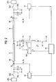
- FIG. 2 an embodiment of an inventive arrangement is shown.
- This arrangement is in accordance with the arrangement according to the FIG. 1 a stator section 10, a track cable A, a further track cable B, a plurality of switches Se, Ss, Sua, Ska, Sub and Skb, a converter URA, a further converter URB, a converter-related measuring device 60, another Inverter-related measuring device 70 and a current control 80 for the magnetic levitation on.
- stator-related, mobile or stationary measuring device which is designated by the reference numeral 100 and the input side is electrically connected to the junction 20 between the two line cables A and B and the stator section 10 and to the neutral point side 30 of the stator.
- the stator-related measuring device 100 On the output side, the stator-related measuring device 100 is connected to an evaluation device 110.
- the stator-related measuring device 110 is designed such that during its operation it measures the current and voltage values Ix, Ux at the connection point 20 between the line cables A, B and the stator section 10 as well as the star point current values Is at the star point side 30 and transmits them to the evaluation device 110 ,
- the evaluation device 110 with the two converter-related measuring devices 60 and 70 only indirectly via the stator-related measuring device 100 in connection, so that the inverter-related measurement results Ia, Ib, Ua, Ub the inverter-related measuring devices 60 and 70 only about the stator-related measuring device 100 to the evaluation device 110 arrive can.
- the evaluation device 110 can also be connected to one of the two converter-related measuring devices 60 or 70 and receive the measurement results of the other measuring devices via them. It is likewise possible to connect the evaluation device 110 directly to all measuring devices 60, 70 and 100, so that an immediate transmission of the measurement results is possible.
- the evaluation device 110 uses these measurement results to determine the electrical parameters of the two extension cables A and B as well as those of the stator section 10 using the quadrupole theory, as will be explained in detail below.
- the conductance matrix of a track cable or a stator section is completely symmetrical in accordance with Equations 2 and 3.
- the characteristics of the diagonal and the transverse admittance as a function of the frequency can be determined by means of various measurements (eg voltage excitations during startup) as a function of the frequency.
- R ', L', G 'and C' The purpose of determining R ', L', G 'and C' is to derive models for the two track cables A, B and the stator section 10.
- the models are used for example for the current control of the maglev train.
- the quadrupole representation as they are based on the FIG. 3 is explained in general, it is based on the arrangement according to the FIG. 2 applied; this shows the FIG. 4 ,
- the switches Se, Ss, Sua, Ska, Sub and Skb are in the FIG. 4 not shown; the switches Se and Ss are assumed to be on.
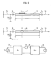
- stator current Ic on the stator section 10 corresponds to the neutral point current Is of the stator section 10; This approximation is very accurate for small frequencies up to 350 hertz.
- the leakage resistance R ⁇ and the leakage inductance L ⁇ may be used for the calculation of the pole wheel voltage UC during operation of the stator portion 10 with a vehicle; this will be explained in more detail below.
- the two route cables A and B are identical.
- Equation 12 The admittances Y Db and Y Cb are previously calculated from equations 22 and 23. Since the currents and voltages in Equation 12 are now known, the components of the conductance matrix [Y a ], namely Y Da and Y Ca are also determinable. Equations 6 to 13 thus also yield the values R a ', L a ', G a 'and C a ' of the track cable A.
- the parameters can thus be determined unambiguously by means of the measured values of the three measuring devices 60, 70 and 100.
- stator section 10 behaves a little differently than during startup without a vehicle.
- FIG. 5 1 shows the stator section 10 with a vehicle F traveling at a speed v, which is currently occupying a relative position x on the stator section 10.
- the vehicle F may be represented electrically as a point voltage Uc.
- Obsch R ⁇ + s ⁇ L ⁇ ⁇ I x .
- the leakage resistance R ⁇ and the leakage inductance L ⁇ can then be determined by means of this harmonic model, as described in the document " Sensorless Control of a 2.4MW Linear Motor for launching roller-coasters "(EPE 2003 - Toulouse (ISBN: 90-75815-07-7), authors: Andre Veltman, Paul van der Hulst, Marco CP Jonker, Jan P. van Gurp ) is described.
- I a I b I x Y Daa 0 Y Ca 0 Y cb Y dbb - Y Dax - Y dbx - Y Ca + Y cb ⁇ U a U b U x
- Equation 33 all measurable quantities (I a , I b , I x , U a , U b and U x ) are combined in a single equation.
- the conductance matrix is now a 3x3 matrix (3 equations).
- the six unknown conductances ( Y Daa , Y Dax , Y Ca , Y Dbb , Y DBx, and Y Cb ) can be easily determined since at least six equations are available.
- the six equations can be established by measuring the currents and the voltages at two different sampling instants, as the currents and the voltages change over time. Incidentally, measurements at several sampling times also statistically improve the quality of parameter estimation.
- I denotes a current vector
- U a voltage vector
- e an error vector (vector with the dimension 3x1)
- Y a real conductance matrix
- ⁇ an estimated conductance matrix
- Equation 36 This formulation is a known problem (according to Gauss), where N denotes the number of measurements at several sampling times. There are many methods for solving Equation 36, for example, by minimizing J.
- Equation 37 is applicable during operation of the maglev when the two switches Se and Ss are closed.
- the phase angle of Ux is measured, with the phase angle of Ux the pole wheel angle ⁇ of the voltage Uc is determined and with the pole wheel angle ⁇ the location of the vehicle is calculated.
Landscapes
- Engineering & Computer Science (AREA)
- Mechanical Engineering (AREA)
- Physics & Mathematics (AREA)
- General Physics & Mathematics (AREA)
- Electric Propulsion And Braking For Vehicles (AREA)
- Control Of Vehicles With Linear Motors And Vehicles That Are Magnetically Levitated (AREA)
- Arc Welding Control (AREA)
Claims (19)
- Procédé de détermination d'un jeu de paramètres, qui décrit des paramètres électriques d'une section de voie d'un réseau à sustentation magnétique, dans lequel la section de voie comprend une section ( 10 ) de stator, formant une section d'entraînement du réseau à sustentation magnétique et un câble ( A, B ) de voie, qui relie la section de stator à un dispositif ( URA, URB ) de convertisseur associé, procédé dans lequel- on mesure les valeurs ( Ua, Ia, Ub, IB ) de courant et de tension au point ( 45, 50 ) de liaison électrique entre le câble de voie et le dispositif de convertisseur et- on détermine, par ces valeurs, les paramètres du jeu de paramètres et on forme ainsi le jeu de paramètres,
caractérisé en ce que- on mesure supplémentairement les valeurs Ux, Ix ) de courant et de tension au point ( 20 ) de liaison électrique entre le câble de voie et la section de stator, ainsi que les valeurs ( Is ) de courant du côté ( 30 ) du point neutre de la section de stator, lorsque la section de stator est reliée électriquement au câble de voie, et- on tient compte également de ces valeurs de mesure supplémentaires, lors de la détermination des paramètres. - Procédé suivant la revendication 1,
caractérisé en ce que
la section de stator est reliée à un autre dispositif ( URB ) de convertisseur par un autre câble ( B ) de voie, et on mesure également les valeurs ( Ib, Ub ) de courant et de tension au point ( 50 ) de liaison électrique entre l'autre câble de voie et l'autre dispositif de convertisseur et on tient compte supplémentairement de ces valeurs de mesure, lors de la détermination des paramètres. - Procédé suivant la revendication 1 ou 2,
caractérisé
en ce que l'on détermine comme paramètre, au moins l'un des paramètres suivants : la résistance ( R ) électrique, l'inductance ( L ), la capacité ( C ), la résistance linéique ( R' ) électrique, l'inductance ( L' ) linéique, la dérivée ( Y' ) de la conductance linéique, la capacité ( C' ) linéique et/ou la conductance ( Y ), que ce soit du câble ( A ) de voie, de l'autre câble ( B ) de voie et/ou de la section ( 10 ) de stator. - Procédé suivant l'une des revendications précédentes, caractérisé
en ce que l'on mesure, respectivement de manière triphasée,
les valeurs du courant et de la tension au point de liaison électrique entre le câble de voie et le dispositif de convertisseur, et les valeurs du courant et de la tension au point de liaison électrique entre le câble de voie et la section de stator, et on les exploite individuellement par ligne de phase. - Procédé suivant l'une des revendications précédentes, caractérisé
en ce que l'on relève les valeurs du courant et de la tension au point de liaison électrique entre le câble de voie et la section de stator, ainsi que les valeurs du courant du côté du point neutre de la section de stator, par un dispositif ( 100 ) mobile de mesure et on les transmet à un dispositif ( 110 ) d'exploitation mobile ou fixe, par lequel on détermine les paramètres. - Procédé suivant l'une des revendications précédentes 1 à 4, caractérisé
en ce que l'on relève les valeurs du courant et de la tension au point de liaison électrique entre le câble de voie et la section de stator, ainsi que les valeurs du courant du côté du point neutre de la section de stator, par un dispositif ( 100 ) de mesure fixe et on les transmet à un dispositif ( 110 ) d'exploitation mobile ou fixe, par lequel on détermine les paramètres. - Procédé suivant l'une des revendications précédentes, caractérisé en ce que- après la détermination des paramètres, on mesure les valeurs du courant et de la tension au point de liaison électrique entre le câble de voie et le dispositif de convertisseur, les valeurs du courant et de la tension au point de liaison électrique entre le câble de voie et la section de stator, ainsi que les valeurs du courant du côté du point neutre de la section de stator, pendant le fonctionnement du réseau à sustentation magnétique, au moins une autre fois, de préférence de façon répétée,- on détermine des paramètres qui s'ensuivent, respectivement à partir des valeurs de mesure, et- on utilise les paramètres respectifs instantanés, pour mettre à jour le jeu de paramètres.
- Procédé suivant l'une des revendications précédentes, caractérisé
en ce que l'on utilise les valeurs du courant et de la tension au point de liaison électrique entre le câble de voie et la section de stator, pour déterminer, pendant le fonctionnement du réseau à sustentation magnétique, la position ( x ) d'un véhicule ( F ) dans la section de stator. - Procédé suivant la revendication 8,
caractérisé
en ce que, pour la détermination de la position de véhicule, on tire parti supplémentairement des valeurs ( Is ) du courant du côté du point neutre de la section de stator. - Procédé suivant l'une des revendications précédentes, caractérisé
en ce que l'on utilise, comme courant ( Ic ) de stator de la section ( 10 ) de stator, le courant ( Is ) mesuré au point neutre. - Procédé suivant l'une des revendications précédentes, caractérisé
en ce que l'on utilise les paramètres, pour le réglage du courant de force de propulsion d'un véhicule ( F ) se trouvant dans la section de stator. - Système de détermination d'un jeu de paramètres, qui décrit des paramètres électriques d'une section de voie d'un réseau à sustentation magnétique, dans lequel la section de voie comprend une section ( 10 ) de stator, formant une section d'entraînement du réseau à sustentation magnétique et un câble ( A, B ) de voie, qui relie la section de stator à un dispositif ( URA, URB ) convertisseur associé,- dans lequel le système comporte un dispositif ( 60, 70 ) de mesure, qui est rapporté au convertisseur, qui est raccordé au point ( 40, 50 ) de liaison électrique entre le câble de voie et le dispositif de convertisseur et qui, pendant son fonctionnement, mesure les valeurs du courant et de la tension au point de liaison, et- dans lequel le système comporte un dispositif ( 110 ) d'exploitation, qui est en liaison avec le dispositif de mesure rapporté au convertisseur et qui détermine, avec les valeurs de mesure du dispositif de mesure rapportées au convertisseur, les paramètres du jeu de paramètres et forme ainsi le jeu de paramètres,
caractérisé en ce que- le système comporte supplémentairement un dispositif ( 100 ) de mesure rapporté au stator, qui est raccordé du côté de l'entrée au point ( 20 ) de liaison électrique entre le câble de voie et la section de stator, ainsi qu'au côté ( 30 ) de point neutre de la section de stator et du côté de la sortie, est en liaison directe ou indirecte avec le dispositif ( 110 ) d'exploitation, et- dans lequel le dispositif de mesure rapporté au stator est tel qu'il mesure, pendant son fonctionnement, les valeurs du courant et de la tension au point de liaison entre le câble de voie et la section de stator, ainsi que les valeurs du courant du côté du point neutre et les transmet au dispositif d'exploitation, dans lequel- le dispositif d'exploitation est tel qu'il tient compte supplémentairement des valeurs de mesure du dispositif de mesure rapporté au stator, lors de la détermination des paramètres et effectue les mesures, lorsque la section de stator est reliée électriquement au câble de voie. - Système suivant la revendication 12,
caractérisé
en ce que le système comporte un autre dispositif ( 70 ) de mesure rapporté au convertisseur, qui est raccordé directement ou indirectement du côté de l'entrée, au point ( 50 ) de liaison électrique entre un autre câble ( B ) de voie et un autre dispositif ( URB ) de convertisseur et du côté de la sortie, au dispositif ( 110 ) d'exploitation, et qui est tel que, pendant son fonctionnement, il mesure les valeurs du courant et de la tension au point de liaison entre l'autre câble de voie et l'autre dispositif de convertisseur et les transmet au dispositif d'exploitation. - Système suivant la revendication 12 ou 13,
caractérisé
en ce que le dispositif ( 100 ) de mesure rapporté au stator et/ou le dispositif d'exploitation sont formés par une unité mobile. - Système suivant l'une des revendications 12 ou 13, caractérisé
en ce que le dispositif ( 100 ) de mesure rapporté au stator et/ou au dispositif d'exploitation sont formés par une unité fixe. - Système suivant l'une des revendications 12 à 15, caractérisé
en ce que le dispositif d'exploitation est tel que- il mesure au moins une autre fois, de préférence de façon répétée, après la détermination des paramètres, les valeurs du courant et de la tension au point de liaison électrique entre le câble de voie et le dispositif de convertisseur, les valeurs du courant et de la tension au point de liaison électrique entre le câble de voie et la section de stator, ainsi que les valeurs du courant du côté du point neutre de la section de stator, pendant le fonctionnement du réseau à sustentation magnétique,- il détermine les paramètres qui s'ensuivent respectivement à partir des valeurs de mesure, et- il utilise les paramètres instantanés respectifs, pour mettre à jour le jeu de paramètres. - Système suivant l'une des revendications 12 à 16, caractérisé
en ce que le dispositif d'exploitation est tel qu'il détermine la position d'un véhicule dans la section de stator, par les valeurs du courant et de la tension au point de liaison électrique entre le câble de voie et la section de stator, pendant le fonctionnement du réseau à sustentation magnétique. - Système suivant la revendication 17,
caractérisé
en ce que le dispositif d'exploitation est tel qu'il tire partie, pour la détermination de la position du véhicule, supplémentairement des valeurs du courant du côté du point neutre de la section de stator. - Réseau à sustentation magnétique comprenant une pluralité de sections de voie,- dans lequel au moins l'une des sections de voie, de préférence toutes les sections de voie, sont équipées respectivement d'un système individuel décentralisé, suivant l'une des revendications précédentes de détermination d'un jeu de paramètres et- dans lequel, pour chaque section de voie dotée d'un système décentralisé, respectivement le courant de force de propulsion de la section de voie est déterminé, en tirant parti de son jeu de paramètres déterminé de manière décentralisée.
Applications Claiming Priority (1)
| Application Number | Priority Date | Filing Date | Title |
|---|---|---|---|
| PCT/DE2007/000784 WO2008131707A1 (fr) | 2007-04-26 | 2007-04-26 | Procédé de détermination d'un ensemble de paramètres décrivant des paramètres électriques d'une section de voie pour un train à sustentation magnétique |
Publications (2)
| Publication Number | Publication Date |
|---|---|
| EP2140278A1 EP2140278A1 (fr) | 2010-01-06 |
| EP2140278B1 true EP2140278B1 (fr) | 2010-11-24 |
Family
ID=39133726
Family Applications (1)
| Application Number | Title | Priority Date | Filing Date |
|---|---|---|---|
| EP07722341A Not-in-force EP2140278B1 (fr) | 2007-04-26 | 2007-04-26 | Procédé de détermination des paramètres électriques d'une section de voie pour un train à sustentation magnétique |
Country Status (7)
| Country | Link |
|---|---|
| US (1) | US8198890B2 (fr) |
| EP (1) | EP2140278B1 (fr) |
| JP (1) | JP5414666B2 (fr) |
| CN (1) | CN101652666B (fr) |
| AT (1) | ATE489637T1 (fr) |
| DE (2) | DE112007003568A5 (fr) |
| WO (1) | WO2008131707A1 (fr) |
Families Citing this family (7)
| Publication number | Priority date | Publication date | Assignee | Title |
|---|---|---|---|---|
| ATE543241T1 (de) * | 2007-05-07 | 2012-02-15 | Siemens Ag | Verfahren und vorrichtung zur bestimmung des lastflusses in einem elektrischen versorgungsnetz |
| WO2015051190A2 (fr) | 2013-10-02 | 2015-04-09 | Velocity Magnetics, Inc. | Système de gestion et de stockage d'énergie à semi-conducteurs |
| CN103954841B (zh) * | 2014-04-11 | 2017-01-11 | 西南交通大学 | 一种中低速磁浮列车悬浮电磁铁电阻参数在线检测方法 |
| GB2530730A (en) * | 2014-09-29 | 2016-04-06 | Bombardier Transp Gmbh | Method of and control system for operating a circuit arrangement |
| JP7406925B2 (ja) * | 2019-05-20 | 2023-12-28 | 日本信号株式会社 | 設備のモニタリング装置 |
| CA3166323A1 (fr) | 2020-02-20 | 2021-08-26 | Velocity Magnetics, Inc. | Procede, systeme et produit programme d'ordinateur pour une alimentation ininterrompue a l'aide d'un reseau d'ultra-condensateurs |
| CN118068128A (zh) * | 2024-02-08 | 2024-05-24 | 云南电网有限责任公司电力科学研究院 | 配电线路移动式区段参数测量方法、装置、设备及介质 |
Family Cites Families (11)
| Publication number | Priority date | Publication date | Assignee | Title |
|---|---|---|---|---|
| GB1057896A (en) * | 1964-05-07 | 1967-02-08 | Funkwerk Dresden Veb | A circuit arrangement for measuring parameters of networks or devices |
| JPH0496605A (ja) * | 1990-08-10 | 1992-03-30 | Toshiba Corp | リニアモータ鉄道の変電所渡り制御装置 |
| JP2710714B2 (ja) * | 1991-08-26 | 1998-02-10 | 三菱電機株式会社 | 浮上式鉄道用リニアシンクロナスモータの誘起電圧検出装置 |
| JPH06261405A (ja) * | 1993-03-09 | 1994-09-16 | Railway Technical Res Inst | リニアシンクロナスモータの故障検出方法 |
| US5569987A (en) * | 1994-03-04 | 1996-10-29 | Siemens Aktiengesellschaft | Power supply system for a long-stator drive for a magnetic levitation train |
| TW404902B (en) * | 1996-06-13 | 2000-09-11 | Siemens Ag | Section-alternation method for a track-system with long-stator linear motor |
| JP2001275375A (ja) * | 2000-03-24 | 2001-10-05 | Central Japan Railway Co | 低速度における速度起電力位相制御装置 |
| SE522376C2 (sv) * | 2000-07-11 | 2004-02-03 | Abb Ab | Metod och anordning för fellokalisering för distributionsnätverk |
| DE10253865B4 (de) * | 2002-11-15 | 2007-05-24 | Siemens Ag | Verfahren zur Ermittelung von ein mehrphasiges elektrotechnisches Betriebsmittel charakterisierenden elektrischen Größen |
| DE102004053301B4 (de) * | 2004-11-04 | 2014-01-23 | Siemens Aktiengesellschaft | Verfahren zum Betreiben eines Magnetschwebefahrzeugs mit einer Schaltungsvorrichtung zur Erhöhung der nutzbaren Motorspannung bei einem Langstatorantrieb |
| DE102007001479B4 (de) * | 2007-01-09 | 2019-10-10 | Siemens Aktiengesellschaft | Verfahren und Einrichtung zum Messen des Pollagewinkels eines Magnetschwebefahrzeugs einer Magnetschwebebahn |
-
2007
- 2007-04-26 EP EP07722341A patent/EP2140278B1/fr not_active Not-in-force
- 2007-04-26 DE DE112007003568T patent/DE112007003568A5/de not_active Withdrawn
- 2007-04-26 AT AT07722341T patent/ATE489637T1/de active
- 2007-04-26 DE DE502007005804T patent/DE502007005804D1/de active Active
- 2007-04-26 JP JP2010504433A patent/JP5414666B2/ja not_active Expired - Fee Related
- 2007-04-26 US US12/597,625 patent/US8198890B2/en not_active Expired - Fee Related
- 2007-04-26 WO PCT/DE2007/000784 patent/WO2008131707A1/fr not_active Ceased
- 2007-04-26 CN CN2007800527323A patent/CN101652666B/zh not_active Expired - Fee Related
Also Published As
| Publication number | Publication date |
|---|---|
| JP2010525776A (ja) | 2010-07-22 |
| CN101652666B (zh) | 2012-06-20 |
| US8198890B2 (en) | 2012-06-12 |
| EP2140278A1 (fr) | 2010-01-06 |
| DE112007003568A5 (de) | 2010-04-08 |
| US20100148750A1 (en) | 2010-06-17 |
| ATE489637T1 (de) | 2010-12-15 |
| CN101652666A (zh) | 2010-02-17 |
| JP5414666B2 (ja) | 2014-02-12 |
| DE502007005804D1 (de) | 2011-01-05 |
| WO2008131707A1 (fr) | 2008-11-06 |
Similar Documents
| Publication | Publication Date | Title |
|---|---|---|
| EP2140278B1 (fr) | Procédé de détermination des paramètres électriques d'une section de voie pour un train à sustentation magnétique | |
| DE69115562T2 (de) | Fehlerlokalisierungsverfahren paralleler Doppelübertragungsleitungen mit N-Ausgängen | |
| EP2608399B1 (fr) | Procédé de détection de défaut de terre pendant l'opération d'un convertisseur | |
| DE102017126704B4 (de) | Energieübertragung im Nullsystem | |
| EP3449557B1 (fr) | Dispositif onduleur, système d'entraînement électrique et procédé de décharge d'un condensateur de circuit intermédiaire dans un dispositif onduleur | |
| CH665735A5 (de) | Verfahren zur ortung einer fehlerstelle in einer uebertragungsleitung. | |
| DE102008034109A1 (de) | Schaltung zur Nachbildung einer elektrischen Last | |
| EP3278448B1 (fr) | Procédé et dispositif d'estimation d'un courant efficace d'un condensateur de circuit intermédiaire pour un onduleur | |
| DE102017220982A1 (de) | Traktionsnetz | |
| DE102023212202A1 (de) | Elektrisches Antriebssystem, Steuerverfahren und relevante Vorrichtung | |
| EP3843230A1 (fr) | Agencement d'infrastructure de charge destiné à la charge des véhicules électriques et procédé de fonctionnement associé | |
| EP3631483B1 (fr) | Procédé et dispositif de localisation de défauts sur une ligne d'alimentation en énergie pour des systèmes à courant continu | |
| EP2481146B1 (fr) | Procédé et dispositif de réglage d'un convertisseur | |
| EP4099531B1 (fr) | Procédé de détermination des paramètres réseau destiné à la commande d'une bobine de petersen | |
| WO2015132060A1 (fr) | Procédé de localisation d'un court-circuit dans un réseau électrique comprenant au moins un tronçon de ligne | |
| DE10253865B4 (de) | Verfahren zur Ermittelung von ein mehrphasiges elektrotechnisches Betriebsmittel charakterisierenden elektrischen Größen | |
| WO2015106979A1 (fr) | Système de transmission de courant continu à haute tension comprenant un commutateur de mise à la terre | |
| EP3385731B1 (fr) | Dispositif de mesure de courant de fuite à la terre | |
| DE102015205954A1 (de) | Verfahren und Vorrichtung zum Schätzen eines Zwischenkreisstroms in einer elektrischen Maschine | |
| EP2197083A2 (fr) | Procédé de modélisation d'un agencement de transformateur | |
| EP3442106A1 (fr) | Dispositif d'entraînement sans capteur de tension primaire | |
| WO2011157469A1 (fr) | Montage pour déterminer une variation de tension de potentiels de conducteur dans un réseau électrique non mis à la terre | |
| EP1085637B1 (fr) | Méthode pour la compensation des charges asymétriques dans des systèmes polyphasés | |
| EP4010955B1 (fr) | Dispositif de commande et montage en pont comportant un tel dispositif de commande | |
| EP1136921A1 (fr) | Méthode de contrôle pour und moteur synchrone ou asynchrone |
Legal Events
| Date | Code | Title | Description |
|---|---|---|---|
| PUAI | Public reference made under article 153(3) epc to a published international application that has entered the european phase |
Free format text: ORIGINAL CODE: 0009012 |
|
| 17P | Request for examination filed |
Effective date: 20090923 |
|
| AK | Designated contracting states |
Kind code of ref document: A1 Designated state(s): AT BE BG CH CY CZ DE DK EE ES FI FR GB GR HU IE IS IT LI LT LU LV MC MT NL PL PT RO SE SI SK TR |
|
| RTI1 | Title (correction) |
Free format text: METHOD FOR DETERMINING ELECTRIC PARAMETERS OF A ROUTE SECTION OF A MAGNETIC SUSPENSION RAILWAY |
|
| GRAP | Despatch of communication of intention to grant a patent |
Free format text: ORIGINAL CODE: EPIDOSNIGR1 |
|
| DAX | Request for extension of the european patent (deleted) | ||
| GRAS | Grant fee paid |
Free format text: ORIGINAL CODE: EPIDOSNIGR3 |
|
| GRAA | (expected) grant |
Free format text: ORIGINAL CODE: 0009210 |
|
| AK | Designated contracting states |
Kind code of ref document: B1 Designated state(s): AT BE BG CH CY CZ DE DK EE ES FI FR GB GR HU IE IS IT LI LT LU LV MC MT NL PL PT RO SE SI SK TR |
|
| REG | Reference to a national code |
Ref country code: GB Ref legal event code: FG4D Free format text: NOT ENGLISH |
|
| REG | Reference to a national code |
Ref country code: CH Ref legal event code: EP |
|
| REG | Reference to a national code |
Ref country code: IE Ref legal event code: FG4D |
|
| REF | Corresponds to: |
Ref document number: 502007005804 Country of ref document: DE Date of ref document: 20110105 Kind code of ref document: P |
|
| REG | Reference to a national code |
Ref country code: NL Ref legal event code: VDEP Effective date: 20101124 |
|
| LTIE | Lt: invalidation of european patent or patent extension |
Effective date: 20101124 |
|
| PG25 | Lapsed in a contracting state [announced via postgrant information from national office to epo] |
Ref country code: LT Free format text: LAPSE BECAUSE OF FAILURE TO SUBMIT A TRANSLATION OF THE DESCRIPTION OR TO PAY THE FEE WITHIN THE PRESCRIBED TIME-LIMIT Effective date: 20101124 |
|
| PG25 | Lapsed in a contracting state [announced via postgrant information from national office to epo] |
Ref country code: SI Free format text: LAPSE BECAUSE OF FAILURE TO SUBMIT A TRANSLATION OF THE DESCRIPTION OR TO PAY THE FEE WITHIN THE PRESCRIBED TIME-LIMIT Effective date: 20101124 Ref country code: IS Free format text: LAPSE BECAUSE OF FAILURE TO SUBMIT A TRANSLATION OF THE DESCRIPTION OR TO PAY THE FEE WITHIN THE PRESCRIBED TIME-LIMIT Effective date: 20110324 Ref country code: LV Free format text: LAPSE BECAUSE OF FAILURE TO SUBMIT A TRANSLATION OF THE DESCRIPTION OR TO PAY THE FEE WITHIN THE PRESCRIBED TIME-LIMIT Effective date: 20101124 Ref country code: PT Free format text: LAPSE BECAUSE OF FAILURE TO SUBMIT A TRANSLATION OF THE DESCRIPTION OR TO PAY THE FEE WITHIN THE PRESCRIBED TIME-LIMIT Effective date: 20110324 Ref country code: BG Free format text: LAPSE BECAUSE OF FAILURE TO SUBMIT A TRANSLATION OF THE DESCRIPTION OR TO PAY THE FEE WITHIN THE PRESCRIBED TIME-LIMIT Effective date: 20110224 Ref country code: FI Free format text: LAPSE BECAUSE OF FAILURE TO SUBMIT A TRANSLATION OF THE DESCRIPTION OR TO PAY THE FEE WITHIN THE PRESCRIBED TIME-LIMIT Effective date: 20101124 Ref country code: NL Free format text: LAPSE BECAUSE OF FAILURE TO SUBMIT A TRANSLATION OF THE DESCRIPTION OR TO PAY THE FEE WITHIN THE PRESCRIBED TIME-LIMIT Effective date: 20101124 Ref country code: CY Free format text: LAPSE BECAUSE OF FAILURE TO SUBMIT A TRANSLATION OF THE DESCRIPTION OR TO PAY THE FEE WITHIN THE PRESCRIBED TIME-LIMIT Effective date: 20101124 Ref country code: SE Free format text: LAPSE BECAUSE OF FAILURE TO SUBMIT A TRANSLATION OF THE DESCRIPTION OR TO PAY THE FEE WITHIN THE PRESCRIBED TIME-LIMIT Effective date: 20101124 |
|
| REG | Reference to a national code |
Ref country code: IE Ref legal event code: FD4D |
|
| PG25 | Lapsed in a contracting state [announced via postgrant information from national office to epo] |
Ref country code: GR Free format text: LAPSE BECAUSE OF FAILURE TO SUBMIT A TRANSLATION OF THE DESCRIPTION OR TO PAY THE FEE WITHIN THE PRESCRIBED TIME-LIMIT Effective date: 20110225 |
|
| PG25 | Lapsed in a contracting state [announced via postgrant information from national office to epo] |
Ref country code: CZ Free format text: LAPSE BECAUSE OF FAILURE TO SUBMIT A TRANSLATION OF THE DESCRIPTION OR TO PAY THE FEE WITHIN THE PRESCRIBED TIME-LIMIT Effective date: 20101124 Ref country code: IE Free format text: LAPSE BECAUSE OF FAILURE TO SUBMIT A TRANSLATION OF THE DESCRIPTION OR TO PAY THE FEE WITHIN THE PRESCRIBED TIME-LIMIT Effective date: 20101124 Ref country code: ES Free format text: LAPSE BECAUSE OF FAILURE TO SUBMIT A TRANSLATION OF THE DESCRIPTION OR TO PAY THE FEE WITHIN THE PRESCRIBED TIME-LIMIT Effective date: 20110307 Ref country code: EE Free format text: LAPSE BECAUSE OF FAILURE TO SUBMIT A TRANSLATION OF THE DESCRIPTION OR TO PAY THE FEE WITHIN THE PRESCRIBED TIME-LIMIT Effective date: 20101124 |
|
| PG25 | Lapsed in a contracting state [announced via postgrant information from national office to epo] |
Ref country code: PL Free format text: LAPSE BECAUSE OF FAILURE TO SUBMIT A TRANSLATION OF THE DESCRIPTION OR TO PAY THE FEE WITHIN THE PRESCRIBED TIME-LIMIT Effective date: 20101124 Ref country code: DK Free format text: LAPSE BECAUSE OF FAILURE TO SUBMIT A TRANSLATION OF THE DESCRIPTION OR TO PAY THE FEE WITHIN THE PRESCRIBED TIME-LIMIT Effective date: 20101124 Ref country code: SK Free format text: LAPSE BECAUSE OF FAILURE TO SUBMIT A TRANSLATION OF THE DESCRIPTION OR TO PAY THE FEE WITHIN THE PRESCRIBED TIME-LIMIT Effective date: 20101124 Ref country code: RO Free format text: LAPSE BECAUSE OF FAILURE TO SUBMIT A TRANSLATION OF THE DESCRIPTION OR TO PAY THE FEE WITHIN THE PRESCRIBED TIME-LIMIT Effective date: 20101124 |
|
| PLBE | No opposition filed within time limit |
Free format text: ORIGINAL CODE: 0009261 |
|
| STAA | Information on the status of an ep patent application or granted ep patent |
Free format text: STATUS: NO OPPOSITION FILED WITHIN TIME LIMIT |
|
| BERE | Be: lapsed |
Owner name: SIEMENS A.G. Effective date: 20110430 |
|
| 26N | No opposition filed |
Effective date: 20110825 |
|
| PG25 | Lapsed in a contracting state [announced via postgrant information from national office to epo] |
Ref country code: MC Free format text: LAPSE BECAUSE OF NON-PAYMENT OF DUE FEES Effective date: 20110430 |
|
| REG | Reference to a national code |
Ref country code: CH Ref legal event code: PL |
|
| REG | Reference to a national code |
Ref country code: DE Ref legal event code: R097 Ref document number: 502007005804 Country of ref document: DE Effective date: 20110825 |
|
| GBPC | Gb: european patent ceased through non-payment of renewal fee |
Effective date: 20110426 |
|
| PG25 | Lapsed in a contracting state [announced via postgrant information from national office to epo] |
Ref country code: MT Free format text: LAPSE BECAUSE OF FAILURE TO SUBMIT A TRANSLATION OF THE DESCRIPTION OR TO PAY THE FEE WITHIN THE PRESCRIBED TIME-LIMIT Effective date: 20101124 Ref country code: IT Free format text: LAPSE BECAUSE OF FAILURE TO SUBMIT A TRANSLATION OF THE DESCRIPTION OR TO PAY THE FEE WITHIN THE PRESCRIBED TIME-LIMIT Effective date: 20101124 |
|
| REG | Reference to a national code |
Ref country code: FR Ref legal event code: ST Effective date: 20111230 |
|
| PG25 | Lapsed in a contracting state [announced via postgrant information from national office to epo] |
Ref country code: BE Free format text: LAPSE BECAUSE OF NON-PAYMENT OF DUE FEES Effective date: 20110430 Ref country code: LI Free format text: LAPSE BECAUSE OF NON-PAYMENT OF DUE FEES Effective date: 20110430 Ref country code: FR Free format text: LAPSE BECAUSE OF NON-PAYMENT OF DUE FEES Effective date: 20110502 Ref country code: CH Free format text: LAPSE BECAUSE OF NON-PAYMENT OF DUE FEES Effective date: 20110430 |
|
| PG25 | Lapsed in a contracting state [announced via postgrant information from national office to epo] |
Ref country code: GB Free format text: LAPSE BECAUSE OF NON-PAYMENT OF DUE FEES Effective date: 20110426 |
|
| PG25 | Lapsed in a contracting state [announced via postgrant information from national office to epo] |
Ref country code: LU Free format text: LAPSE BECAUSE OF NON-PAYMENT OF DUE FEES Effective date: 20110426 |
|
| REG | Reference to a national code |
Ref country code: AT Ref legal event code: MM01 Ref document number: 489637 Country of ref document: AT Kind code of ref document: T Effective date: 20120426 |
|
| PG25 | Lapsed in a contracting state [announced via postgrant information from national office to epo] |
Ref country code: AT Free format text: LAPSE BECAUSE OF NON-PAYMENT OF DUE FEES Effective date: 20120426 |
|
| PG25 | Lapsed in a contracting state [announced via postgrant information from national office to epo] |
Ref country code: TR Free format text: LAPSE BECAUSE OF FAILURE TO SUBMIT A TRANSLATION OF THE DESCRIPTION OR TO PAY THE FEE WITHIN THE PRESCRIBED TIME-LIMIT Effective date: 20101124 |
|
| PG25 | Lapsed in a contracting state [announced via postgrant information from national office to epo] |
Ref country code: HU Free format text: LAPSE BECAUSE OF FAILURE TO SUBMIT A TRANSLATION OF THE DESCRIPTION OR TO PAY THE FEE WITHIN THE PRESCRIBED TIME-LIMIT Effective date: 20101124 |
|
| PGFP | Annual fee paid to national office [announced via postgrant information from national office to epo] |
Ref country code: DE Payment date: 20180619 Year of fee payment: 12 |
|
| REG | Reference to a national code |
Ref country code: DE Ref legal event code: R119 Ref document number: 502007005804 Country of ref document: DE |
|
| PG25 | Lapsed in a contracting state [announced via postgrant information from national office to epo] |
Ref country code: DE Free format text: LAPSE BECAUSE OF NON-PAYMENT OF DUE FEES Effective date: 20191101 |