EP2143456B1 - Kanülenschutz und Einwegspritzensystem - Google Patents
Kanülenschutz und Einwegspritzensystem Download PDFInfo
- Publication number
- EP2143456B1 EP2143456B1 EP08159931A EP08159931A EP2143456B1 EP 2143456 B1 EP2143456 B1 EP 2143456B1 EP 08159931 A EP08159931 A EP 08159931A EP 08159931 A EP08159931 A EP 08159931A EP 2143456 B1 EP2143456 B1 EP 2143456B1
- Authority
- EP
- European Patent Office
- Prior art keywords
- syringe
- cannula
- sleeve
- length
- bellows
- Prior art date
- Legal status (The legal status is an assumption and is not a legal conclusion. Google has not performed a legal analysis and makes no representation as to the accuracy of the status listed.)
- Not-in-force
Links
Images


Classifications
-
- A—HUMAN NECESSITIES
- A61—MEDICAL OR VETERINARY SCIENCE; HYGIENE
- A61M—DEVICES FOR INTRODUCING MEDIA INTO, OR ONTO, THE BODY; DEVICES FOR TRANSDUCING BODY MEDIA OR FOR TAKING MEDIA FROM THE BODY; DEVICES FOR PRODUCING OR ENDING SLEEP OR STUPOR
- A61M5/00—Devices for bringing media into the body in a subcutaneous, intra-vascular or intramuscular way; Accessories therefor, e.g. filling or cleaning devices, arm-rests
- A61M5/50—Devices for bringing media into the body in a subcutaneous, intra-vascular or intramuscular way; Accessories therefor, e.g. filling or cleaning devices, arm-rests having means for preventing re-use, or for indicating if defective, used, tampered with or unsterile
- A61M5/508—Means for preventing re-use by disrupting the piston seal, e.g. by puncturing
-
- A—HUMAN NECESSITIES
- A61—MEDICAL OR VETERINARY SCIENCE; HYGIENE
- A61M—DEVICES FOR INTRODUCING MEDIA INTO, OR ONTO, THE BODY; DEVICES FOR TRANSDUCING BODY MEDIA OR FOR TAKING MEDIA FROM THE BODY; DEVICES FOR PRODUCING OR ENDING SLEEP OR STUPOR
- A61M5/00—Devices for bringing media into the body in a subcutaneous, intra-vascular or intramuscular way; Accessories therefor, e.g. filling or cleaning devices, arm-rests
- A61M5/178—Syringes
- A61M5/31—Details
- A61M5/32—Needles; Details of needles pertaining to their connection with syringe or hub; Accessories for bringing the needle into, or holding the needle on, the body; Devices for protection of needles
- A61M5/3205—Apparatus for removing or disposing of used needles or syringes, e.g. containers; Means for protection against accidental injuries from used needles
- A61M5/321—Means for protection against accidental injuries by used needles
- A61M5/3243—Means for protection against accidental injuries by used needles being axially-extensible, e.g. protective sleeves coaxially slidable on the syringe barrel
- A61M5/326—Fully automatic sleeve extension, i.e. in which triggering of the sleeve does not require a deliberate action by the user
-
- A—HUMAN NECESSITIES
- A61—MEDICAL OR VETERINARY SCIENCE; HYGIENE
- A61M—DEVICES FOR INTRODUCING MEDIA INTO, OR ONTO, THE BODY; DEVICES FOR TRANSDUCING BODY MEDIA OR FOR TAKING MEDIA FROM THE BODY; DEVICES FOR PRODUCING OR ENDING SLEEP OR STUPOR
- A61M5/00—Devices for bringing media into the body in a subcutaneous, intra-vascular or intramuscular way; Accessories therefor, e.g. filling or cleaning devices, arm-rests
- A61M5/50—Devices for bringing media into the body in a subcutaneous, intra-vascular or intramuscular way; Accessories therefor, e.g. filling or cleaning devices, arm-rests having means for preventing re-use, or for indicating if defective, used, tampered with or unsterile
- A61M5/5013—Means for blocking the piston or the fluid passageway to prevent illegal refilling of a syringe
- A61M5/502—Means for blocking the piston or the fluid passageway to prevent illegal refilling of a syringe for blocking the piston
Definitions
- This invention relates to a cannula guard according to the preamble of claim 1.
- This cannula guard is used to cover a cannula attached to a syringe, in particular to avoid unwanted injury to the cannula and contamination of the cannula just before use on the patient.
- the invention also relates to a disposable syringe system having such a needle guard.
- the cannula protector comprises a tubular sleeve and a bellows, which partially completely surround at least the area of the cannula together with the sleeve.
- the needle guard also includes a radially acting clamping spring which serves to hold the inserted disposable syringe in the desired position, or to activate the protective mechanism.
- a needle guard with a collapsing shell is known.
- the needle guard relates to a catheter in which a foldable bellows which can be pushed against a spring force is used as the collapsing sheath.
- the sheath safely and automatically shields the sharp tip of the introducer needle of the catheter after the needle has been used to place the catheter in a patient.
- the protective device has a complicated structure with many individual parts and a complicated spring-latch mechanism for activating the protective mechanism.
- the bellows is formed of a flexible impermeable, non-elastic material having low elongation properties.
- the individual parts of the protective sleeve are complex, for example, assembled by interference fit, ultrasonic welding or application of a standard adhesive.
- a multi-part cannula protection with an outer sleeve and an inner sleeve known.
- Extensive mechanical means are provided between the inner and outer sleeves to fix the sleeves together for the purpose of injection and to manually or automatically release a return mechanism to "sink" the needle within the outer sleeve.
- a coil spring is made integral with the sleeve in the inner sleeve.
- the object is achieved by a needle guard according to the appended claim 1 and by a disposable syringe system according to claim 10.
- An inventive needle guard has a tubular sleeve for axially movable receiving a syringe, preferably a disposable syringe.
- the tubular sleeve is closed at its one end by a base, wherein the base has an opening for the passage of a cannula plugged onto the disposable syringe.
- a compressible spring element is designed as a bellows and integrally formed, wherein the bellows has a bias, so that it assumes its original shape after compression in the axial direction after discharge.
- Sleeve and bellows are dimensioned in the overall length so that the disposable syringe with attached cannula is completely enclosed by the cannula protection in its entire axial extent at least in the region of the cannula.
- the bellows must be compressible about the length of the cannula so that it can emerge substantially completely from the opening when the disposable syringe is inserted for the purpose of injection.
- the cannula protection is kept in different sizes and with bellows of different lengths.
- the sleeve length of the sleeve is shorter than the length of the syringe barrel of the syringe to be inserted.
- the compression length is at least equal to the length of the cannula of the syringe to be inserted.
- the sum of sleeve length and elongated length of the bellows is at least equal to the sum of the length of the syringe barrel and the length of the cannula
- the needle guard further comprises at least one radially acting clamping spring which is arranged in the region of the sleeve is.
- a plurality of clamping springs are distributed uniformly around the circumference of the sleeve.
- the clamping spring or the clamping springs can be actuated by finger pressure of two fingers gripping the sleeve in order to press the clamping spring or the clamping springs against the inserted disposable syringe and to keep it in the instantaneous position. This is for injection purposes when the cannula protrudes from the opening.
- the bellows under pressure so when moving the syringe with the cannula in the direction of opening, collapsible and he takes elastic his original shape after relief again, namely when the clamping springs are released, especially when dropping the syringe.
- the cannula protection is particularly simple and inexpensive, z. B. by injection molding, can be produced.
- the cannula protection according to the invention can be used in conjunction with conventional syringes without having to change their design.
- the bellows has a helical shape. This is preferably produced by injection molding through a rotary core, which is rotated out after casting from the finished needle protection. In this way, the cannula protection can easily be removed from the mold without having to split it into several parts. The entire cannula protection can therefore be formed in one piece.
- two clamping springs are arranged radially opposite one another on the sleeve, or four clamping springs are distributed uniformly around the circumference. But it can also be a different number of clamping springs are selected.
- the clamping springs are integrally formed with the sleeve by tongue-shaped clamping springs are formed, which have a protruding over the wall of the sleeve portion for ease of operation.
- the respective radially opposite positions of two clamping springs favor the actuation of the clamping mechanism when gripping the syringe with two fingers of the operator.
- a scale of the inserted disposable syringe can be observed despite enclosing cannula protection.
- This can advantageously be achieved by one or more axially extending slots in the sleeve. But it is also possible to manufacture the needle protection completely or partially from a transparent plastic material.
- the cannula protection according to the invention is integrally formed or divided into two in the axial direction and can be plugged together via a latching mechanism.
- the opening for the passage of the cannula preferably has a circular shape, but other shapes, such as those of a cross, are possible.
- a particularly advantageous disposable syringe system comprises a cannula protector of the type described above and a disposable syringe, wherein the disposable syringe or a part thereof can be permanently locked by means of a connection catch with the cannula protector.
- the disposable syringe system according to the invention prevents a Further use of the disposable syringe inserted in the needle guard.
- the piston of the disposable syringe is provided with a predetermined breaking edge to prevent reuse, and in the interior of the syringe barrel near the outlet a cross-sectionally tapered web is provided, which destroys the predetermined breaking edge upon impact with the web, so that the piston is no longer sealed in the disposable syringe after use.
- Fig. 1 shows a needle protection 01 in a spatial representation.
- the needle guard 01 comprises a tubular sleeve 02.
- the sleeve 02 is closed at its first end by a base 03, which has an opening 04 for the passage of a cannula 05 (FIGS. Fig. 2 ) a disposable syringe 09 ( Fig. 2 ) having.
- the illustrated opening 04 has a circular shape. However, it is also possible to use other suitable shapes, such as a cross or the like.
- a bellows 06 is integrally formed.
- the bellows 06 has a bias and is collapsible or compressible in the axial direction under pressure. When relieving the bellows 06 takes its original shape again.
- the bellows 06 is preferably formed with a coiled wall, so that it works like a helical spring.
- the bellows 06 is shown here in a fully stretched state. The restoring force to be applied by the bellows in the compressed state must be so great that the sleeve 02 is guided axially forward on the syringe and receives the cannula as soon as no force is impressed on the entire system by the user.
- the counterforce of the bellows to be overcome in the injection should be as small as possible so as not to complicate the injection.
- two projections 07 are preferably arranged, which hold the needle protection 01 with two fingers when the disposable syringe is inserted into the needle guard or during the injection.
- radially acting clamping springs 08 are arranged in the illustrated embodiment, which hold the inserted disposable syringe in the instantaneous position in the sleeve 02 at a radially directed pressure on them, preferably with a cannula exposed for injection.
- the disposable syringe 09 includes in a known manner a syringe barrel 11 with a nozzle 12 for attaching the cannula 05.
- the disposable syringe 09 further includes a syringe plunger 13 with an actuating plate 14 for pressing the syringe plunger 13 in the syringe barrel 11th
- the entire disposable syringe 09 is axially displaceable together with the attached cannula 05 within the needle guard 01 and can be fixed by pressing the clamping elements 08 in the respective position.
- the sleeve 02 has between the Base plate 03 and the projection 07 at the other end a sleeve length which is shorter than the length of the Spritzenkobens 11.
- the bellows 06 is shown in a largely collapsed position, which can be maintained only when the user actuates the clamping elements 08 and thus clamps the syringe in the sleeve 02. Unlike in the Fig.
- the free end 15 of the bellows 06 strikes on actuation of the syringe to a stop ring 20 of the syringe plunger 11, so that the bellows is compressed when a force is exerted in the axial direction on the syringe plunger or the actuating plate 14 of the syringe plunger.
- the friction between syringe barrel 11 and inner wall of the sleeve 02 is to be kept so small by sufficient clearance that the syringe can be pushed into the sleeve 02 substantially only against the resistance of the bellows.
- the user exposes the cannula 05 by inserting the syringe into the sleeve 02.
- the injection can then be set as usual. If the user puts the syringe out of his hand, the clamping force is eliminated, the bellows 06 relaxes and pushes the sleeve 02 over the cannula 05.
- the syringe plunger 13 is in the in Fig. 2 shown state far inserted into the syringe barrel 11. This corresponds to the moment during injection or when drawing the injection solution into the syringe.
- the cannula protection 01 together with the disposable syringe 09 forms an advantageous disposable syringe system, which can be equipped with the cannula 05 and filled with an injection solution in this completed form.
- Fig. 3 shows a spatial representation of the disposable syringe system according to Fig. 2
- the needle guard 01 has axially extending viewing slits 18, preferably four distributed on the circumference, which serve to observe a scale 19 of the disposable syringe 09.
- the observation possibility is also required, for example, to be able to observe the influx of blood into the syringe.
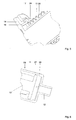
- Fig. 4 shows in three views a split in the axial direction needle protector 01, which can be assembled from two halves 21.
- This embodiment is particularly inexpensive to manufacture, since the injection molds can be made much easier.
- the bellows 06 can be formed in a non-coiled structure.
- Figs. B) and c) the locking mechanism for connecting the halves 21 is shown in detail.
- the two halves 21 opposite each have a nose 22 and a groove 23.
- a ready-prepared or mounted disposable syringe can be advantageously inserted into one of the halves and encapsulated by snapping the second half. This simplifies handling. Special requirements for the tightness are not provided on the needle guard 01, which is why the two-part embodiment can preferably be used.
- Fig. 5 shows a detail view of a latching mechanism of a disposable syringe system similar to that shown in FIG Fig. 2 already described.
- the bellows 06 has a fixing portion 24 which engages in the provided on the syringe barrel 11 of the disposable syringe 09 locking groove 17 during assembly.
- the latching hook 16 of the syringe piston 13 also engages after complete actuation in this locking groove 17, whereby a repeated opening or use of the disposable syringe is reliably prevented.
- Fig. 6 shows a detailed view of a preferred embodiment of a disposable syringe to be used in the disposable syringe 09.
- the syringe barrel 11 has in its interior near the outlet 12 provided with the nozzle on a web 26 which provided with a syringe plunger 13, tapered in cross-section predetermined breaking edge 27 during closing Pressing the disposable syringe 09 meets and destroys it.
- a syringe plunger 13 By destroying the predetermined breaking edge 27 of the syringe plunger 13 is no longer sealingly mounted in the syringe barrel 11, whereby a re-drawing an injection solution into the disposable syringe is no longer possible.
- the combination of the features described leads to a disposable syringe system which meets high hygiene requirements.
- the risk of injury to the cannula is minimized because the cannula is secured by the cannula guard as soon as the syringe is removed from the hand. At the same time reuse is prevented.
Landscapes
- Health & Medical Sciences (AREA)
- Engineering & Computer Science (AREA)
- Heart & Thoracic Surgery (AREA)
- Vascular Medicine (AREA)
- Anesthesiology (AREA)
- Biomedical Technology (AREA)
- Hematology (AREA)
- Life Sciences & Earth Sciences (AREA)
- Animal Behavior & Ethology (AREA)
- General Health & Medical Sciences (AREA)
- Public Health (AREA)
- Veterinary Medicine (AREA)
- Environmental & Geological Engineering (AREA)
- Infusion, Injection, And Reservoir Apparatuses (AREA)
Description
- Die Erfindung betrifft einen Kanülenschutz gemäß dem Oberbegriff des Anspruchs 1. Dieser Kanülenschutz dient zur Abdeckung einer an einer Spritze angebrachten Kanüle, insbesondere um ungewollte Verletzungen an der Kanüle sowie eine Kontamination der Kanüle kurz vor deren Verwendung am Patienten zu vermeiden. Die Erfindung betrifft außerdem ein Einwegspritzensystem mit einem solche Kanülenschutz.
- Der Kanülenschutz umfasst eine rohrförmige Hülse und einen Faltenbalg, welcher teilweise gemeinsam mit der Hülse zumindest den Bereich der Kanüle vollständig umschließt. Der Kanülenschutz umfasst auch eine radial wirkende Klemmfeder, welche dazu dient, die eingelegte Einwegspritze in der gewünschten Position zu halten, bzw. den Schutzmechanismus zu aktivieren.
- Diverse Nadelschutzvorrichtungen sind aus dem Stand der Technik bekannt. Die kurzfristige Aufbewahrung von zur Injektion vorbereiteten Einwegspritzen bis zur Durchführung der Injektion, sowie die Entsorgung bereits benutzter Einwegspritzen ist aufgrund der Gefahr der Ansteckung mit verschiedenen Erregern und aufgrund der Verletzungsgefahr an der freiliegenden Kanüle von besonderer Bedeutung.
- Aus der
DE 100 44 383 C2 ist eine Nadelschutzvorrichtung bekannt, welche an einer auf eine Einwegspritze aufsteckbaren Kanüle verwendet wird. Die Nadelschutzvorrichtung umfasst einen Träger und eine Nadelhülle. Die Nadelhülle kann aus einer zurückgeschobenen Stellung in eine Schutzstellung, in der sie die Einstechnadel bis wenigsten zu der Nadelspitze umgibt, verbracht werden. Die Nadelhülle umfasst einen Falten balg und Blockierelemente, welche ein Blockierteleskop bilden, welches in einem ausgefahrenen Zustand eine Blockierstellung einnimmt. Diese Nadelschutzvorrichtung betrifft ausschließlich die Kanüle, welche nach Gebrauch einer Einwegspritze wieder von dieser entfernt werden kann. - Aus der
EP 0 763 369 B1 ist eine Nadelschutzvorrichtung mit einer kollabierenden Hülle bekannt. Der Nadelschutz betrifft einen Katheter, bei welchem als kollabierende Hülle ein sich gegen eine Federkraft aufschiebbarer Faltenbalg verwendet wird. Die Hülle schirmt sicher und automatisch die scharfe Spitze der Einführungsnadel des Katheters ab, nachdem die Nadel zum Legen des Katheters bei einem Patienten benutzt worden ist. Die Schutzvorrichtung hat einen komplizierten Aufbau mit vielen Einzelteilen und einen komplizierten Feder-Rast-Mechanismus zur Aktivierung des Schutzmechanismus. Der Faltenbalg ist aus einem flexiblen undurchlässigen, nicht elastischen Material mit niedrigen Dehnungseigenschaften gebildet. Die Einzelteile der Schutzhülse werden aufwendig, beispielsweise durch Presspassung, Ultraschallschweißen oder Anwendung eines Standardklebers zusammengefügt. - Aus der
US 2004/0127857 ist ein mehrteiliger Kanülenschutz mit einer äußeren Hülse und einer inneren Schutzhülse bekannt. Zwischen innerer und äußerer Hülse sind aufwendige mechanische Mittel vorgesehen, um die Hülsen zum Zweck der Injektion gegeneinander zu fixieren und zur manuellen oder automatischen Freigabe eines Rückstellmechanismus, um die Nadel innerhalb der äußeren Hülse zu "versenken". In einer Ausführungsform ist in der inneren Hülse eine Spiralfeder integral mit der Hülse gefertigt. - Die Aufgabe wird durch einer Kanülenschutz gemäß dem beigefügten Anspruch 1 und durch ein Einwegspritzensystem gemäß Anspruch 10 gelöst.
- Ein erfindungsgemäßer Kanülenschutz weist eine rohrförmige Hülse zur axialbeweglichen Aufnahme einer Spritze, vorzugsweise einer Einwegspritze auf. Die rohrförmige Hülse ist an ihrem einen Ende durch eine Grundfläche verschlossen, wobei die Grundfläche eine Öffnung für den Durchlass einer auf die Einwegspritze aufgesteckten Kanüle aufweist. Am anderen Ende der Hülse ist ein stauchbares Federelement als Faltenbalg ausgeführt und einstückig angeformt, wobei der Faltenbalg eine Vorspannung aufweist, so dass er nach einem Zusammendrücken in axialer Richtung nach Entlastung seine ursprüngliche Form wieder einnimmt.
- Hülse und Faltenbalg sind in der Gesamtlänge so dimensioniert, dass die Einwegspritze mit aufgesteckter Kanüle von dem Kanülenschutz in ihrer gesamten axialen Erstreckung zumindest im Bereich der Kanüle vollständig umschlossen ist. Der Faltenbalg muss insgesamt etwa um die Länge der Kanüle zusammendrückbar sein, damit diese bei eingelegter Einwegspritze zum Zwecke der Injektion im Wesentlichen vollständig aus der Öffnung austreten kann. Vorteilhafterweise wird der Kanülenschutz in verschiedenen Größen und mit jeweils verschieden langen Faltenbälgen bereitgehalten.
- Die Hülsenlänge der Hülse ist kürzer als die Länge des Spritzenzylinders der einzulegenden Spritze. Die Stauchungslänge ist mindestens gleich der Länge der Kanüle der einzulegenden Spritze. Die Summe aus Hülsenlänge und gestreckter Länge des Faltenbalgs ist mindestens gleich der Summe aus Länge des Spritzenzylinders und Länge der Kanüle
- Bei einem axial gerichteten Druck auf den Faltenbalg wird die Einwegspritze in dem Kanülenschutz verschoben, wodurch die Kanüle durch die Öffnung in der Grundfläche hindurch freigegeben wird.
- Der Kanülenschutz umfasst weiterhin mindestens eine radial wirkende Klemmfeder, welche im Bereich der Hülse angeordnet ist. Vorzugsweise sind mehrere Klemmfedern um den Umfang der Hülse gleichmäßig verteilt vorgesehen.
- Die Klemmfeder bzw. die Klemmfedern können mittels Fingerdruck zweier die Hülse greifender Finger betätigt werden, um die Klemmfeder bzw. die Klemmfedern gegen die eingelegte Einwegspritze zu drücken und diese in der augenblicklichen Position zu halten. Dies erfolgt zu Injektionszwecken, wenn die Kanüle aus der Öffnung hinausragt.
- Erfindungsgemäß ist der Faltenbalg unter Druck, also beim Verschieben der Spritze mit der Kanüle in Richtung Öffnung, zusammenschiebbar und er nimmt federelastisch seine Ursprungsform nach der Entlastung wieder ein, nämlich wenn die Klemmfedern freigegeben werden, insbesondere beim Ablegen der Spritze.
- Die Vorteile der Erfindung sind insbesondere darin zu sehen, dass der Kanülenschutz besonders einfach und preisgünstig, z. B. durch ein Spritzgießverfahren, herstellbar ist. Der erfindungsgemäße Kanülenschutz lässt sich in Verbindung mit herkömmlichen Spritzen verwenden, ohne dass deren Bauform verändert werden muss.
- In einer besonders bevorzugten Ausführungsform der Erfindung weist der Faltenbalg eine Schraubenform auf. Diese ist vorzugsweise im Spritzgießverfahren durch einen Drehkern herstellbar, welcher nach dem Gießen aus dem fertigen Kanülenschutz herausgedreht wird. Auf diese Weise lässt sich der Kanülenschutz leicht entformen, ohne dass er in mehrere Teile zertrennt werden muss. Der gesamte Kanülenschutz kann daher einteilig ausgeformt sein.
- Vorteilhafterweise sind an der Hülse zwei Klemmfedern radial gegenüberliegend, oder vier Klemmfedern gleichmäßig um den Umfang verteilt angeordnet. Es kann aber ebenso eine andere Anzahl an Klemmfedern gewählt werden. Die Klemmfedern sind einstückig mit der Hülse ausgebildet, indem zungenförmige Klemmfedern geformt werden, die zur leichteren Betätigung einen über die Wandung der Hülse hervorstehenden Abschnitt aufweisen. Die jeweils radial gegenüberliegenden Positionen zweier Klemmfedern begünstigen das Betätigen des Klemmmechanismus beim Greifen der Spritze mit zwei Fingern des Bedieners.
- Vorzugsweise kann eine Skala der eingelegten Einwegspritze trotz umschließenden Kanülenschutzes beobachtet werden. Dies kann vorteilhafterweise durch einen oder mehrere axial verlaufende Schlitze in der Hülse erreicht werden. Es ist aber auch möglich, den Kanülenschutz vollständig oder abschnittsweise aus einem durchsichtigen Kunststoffmaterial zu fertigen.
- Der Kanülenschutz ist erfindungsgemäß einstückig ausgebildet oder in axialer Richtung zweigeteilt und über einen Rastmechanismus zusammensteckbar.
- Die Öffnung zum Durchlass der Kanüle hat vorzugsweise eine kreisrunde Form, aber auch andere Formen, wie beispielsweise die eines Kreuzes, sind möglich.
- Ein besonders vorteilhaftes Einwegspritzensystem umfasst einen Kanülenschutz der zuvor beschriebenen Art und eine Einwegspritze, wobei die Einwegspritze oder ein Teil davon über eine Verbindungsraste mit dem Kanülenschutz unlösbar arretierbar ist. Das erfindungsgemäße Einwegspritzensystem verhindert eine weitere Verwendung der in den Kanülenschutz eingelegten Einwegspritze.
- In einer bevorzugten Ausführungsform des Einwegspritzensystems ist der Kolben der Einwegspritze mit einer Sollbruchkante zur Vermeidung der Wiederverwendung versehen, und im Inneren des Spritzenzylinders ist nahe des Auslasses ein im Querschnitt verjüngter Steg vorgesehen, welcher die Sollbruchkante bei deren Auftreffen auf den Steg zerstört, sodass der Kolben nach Gebrauch nicht mehr dichtend in der Einwegspritze gelagert ist.
- In einer zweiten bevorzugten Ausführungsform des Einwegspritzensystems ist an einem Betätigungselement der Einwegspritze und an dem Kanülenschutz ein Verschlussmechanismus vorgesehen, der nach einmaliger schließender Betätigung des Spritzenkolbens einrastet und dadurch eine wiederholte Benutzung der Einwegspritze verhindert.
- Bevorzugte Ausführungsformen der Erfindung werden nachfolgend anhand der Figuren näher erläutert. Es zeigen:
- Fig. 1:
- eine räumliche Ansicht eines Kanülenschutzes;
- Fig. 2:
- eine Längsschnittdarstellung des Kanülenschutzes mit eingelegter Einwegspritze;
- Fig. 3:
- eine räumliche Ansicht einer zweiten Ausführungsform des Kanülenschutzes;
- Fig. 4:
- drei räumliche Detaildarstellungen eines zweiteilig ausgeführten Kanülenschutzes;
- Fig. 5:
- eine Detailansicht eines Verschlussmechanismus eines Einwegspritzensystems;
- Fig. 6:
- eine Detailansicht einer Einwegspritze.
-
Fig. 1 zeigt einen Kanülenschutz 01 in einer räumlichen Darstellung. Der Kanülenschutz 01 umfasst eine rohrförmige Hülse 02. Die Hülse 02 ist an ihrem ersten Ende durch eine Grundfläche 03 verschlossen, welche eine Öffnung 04 für den Durchlass einer Kanüle 05 (Fig. 2 ) einer Einwegspritze 09 (Fig. 2 ) aufweist. Die dargestellte Öffnung 04 hat eine kreisrunde Form. Es ist aber ebenso möglich, andere geeignete Formen, wie beispielsweise ein Kreuz oder ähnliches, zu verwenden. - An einem der Grundfläche 03 gegenüberliegenden Ende der Hülse 02 ist ein Faltenbalg 06 einstückig angeformt. Der Faltenbalg 06 weist eine Vorspannung auf und ist in axialer Richtung unter Druck zusammenschiebbar bzw. stauchbar. Bei Entlastung nimmt der Faltenbalg 06 seine ursprüngliche Form wieder ein. Der Faltenbalg 06 ist vorzugsweise mit einer gewendelten Wand gebildet, sodass er wie eine Schraubenfeder arbeitet. Der Faltenbalg 06 ist hier in völlig gestrecktem Zustand dargestellt. Die vom Faltenbalg im gestauchten Zustand aufzubringende Rückstellkraft muss so groß sein, dass die Hülse 02 axial auf der Spritze nach vorn geleitet und die Kanüle aufnimmt, sobald vom Benutzer keine Kraft auf das gesamte System eingeprägt wird. Gleichzeitig soll die bei der Injektion zu überwindenden Gegenkraft des Faltenbalgs so klein wie möglich sein, um die Injektion nicht zu erschweren.
- Zwischen der Hülse 02 und dem Faltenbalg 06 sind vorzugsweise zwei Vorsprünge 07 angeordnet, die dem Halten des Kanülenschutzes 01 mit zwei Fingern dienen, wenn die Einwegspritze in den Kanülenschutz eingesetzt wird oder während der Injektion.
- Auf dem Umfang der Hülse 02 sind in der dargestellten Ausführungsform vier radial wirkende Klemmfedern 08 angeordnet, welche bei einem radial auf sie gerichteten Druck die eingelegte Einwegspritze in der augenblicklichen Position in der Hülse 02 halten, vorzugsweise mit zur Injektion freigelegter Kanüle.
- Die Anordnung von vier Klemmfedern 08 um den Umfang verteilt hat sich als vorteilhaft herausgestellt, weil dadurch der Kanülenschutz 01 mit eingelegter Einwegspritze nicht gedreht werden muss, um mit zwei Fingern die Klemmfedern zu bedienen. Die gewohnte Einhandbedienung der Spritze ist auch mit dem Kanülenschutz 01 weiterhin möglich.
- Die Klemmfedern 08 sind als federnde Zungen einstückig mit der Hülse 02 ausgebildet und besitzen für eine leichtere Betätigung einen radialen Überstand 10.
-
Fig. 2 zeigt eine Längsschnittdarstellung des erfindungsgemäßen Kanülenschutzes 01 mit einer darin eingelegten Einwegspritze 09. Die Einwegspritze 09 umfasst in bekannter Weise einen Spritzenzylinder 11 mit einer Düse 12 zum Aufstecken der Kanüle 05. Die Einwegspritze 09 umfasst weiterhin einen Spritzenkolben 13 mit einer Betätigungsplatte 14 zum Eindrücken des Spritzenkolbens 13 in den Spritzenzylinder 11. - Die gesamte Einwegspritze 09 ist gemeinsam mit der aufgesteckten Kanüle 05 innerhalb des Kanülenschutzes 01 axial verschiebbar und durch Drücken der Klemmelemente 08 in der jeweiligen Position festlegbar. Die Hülse 02 besitzt zwischen der Grundplatte 03 und dem Vorsprung 07 am anderen Ende eine Hülsenlänge, die kürzer als die Länge des Spritzenkobens 11 ist. Der Faltenbalg 06 ist in weitgehend zusammengeschobener Position dargestellt, die nur aufrecht erhalten werden kann, wenn der Nutzer die Klemmelemente 08 betätigt und damit die Spritze in der Hülse 02 festklemmt. Anders als in der in
Fig. 2 zu Verständniszwecken gewählten Darstellung, schlägt das freie Ende 15 des Faltenbalgs 06 beim Betätigen der Spritze an einem Anschlagring 20 des Spritzenkolbens 11 an, sodass der Faltenbalg gestaucht wird, wenn auf den Spritzenkolben oder die Betätigungsplatte 14 des Spritzenkolbens eine Kraft in axialer Richtung ausgeübt wird. Die Reibung zwischen Spritzenzylinder 11 und Innenwand der Hülse 02 ist durch genügend Spiel so klein zu halten, dass die Spritze im Wesentlichen nur gegen den Widerstand des Faltenbalgs in die Hülse 02 geschoben werden kann. - Die Stauchungslänge des Faltenbalgs 06, um welcher diese mindestens zusammen gestaucht werden kann und um die er sich nach Wegfall der Stauchungskraft mindestens wieder ausdehnt, entspricht mindestens der Länge de Kanüle 05 (ggf. abzüglich ihres Sockels), um ein vollständiges Abdecken der Kanüle beim Ausdehnen des Faltenbalgs und der damit einhergehenden Verlagerung der Hülse 02 zu erreichen.
- Vor der eigentlichen Injektion legt der Benutzer die Kanüle 05 frei, indem die Spritze in die Hülse 02 eingeschoben wird. Die Injektion kann dann wie gewohnt gesetzt werden. Legt der Nutzer die Spritze aus der Hand, entfällt die Klemmkraft, der Faltenbalg 06 entspannt sich und schiebt dabei die Hülse 02 über die Kanüle 05.
- Der Spritzenkolben 13 ist in dem in
Fig. 2 dargestellten Zustand weit in den Spritzenzylinder 11 eingeschoben. Dies entspricht dem Moment während der Injektion bzw. beim Aufziehen der Injektionslösung in die Spritze. - In der in
Fig. 2 dargestellten Ausführungsform bildet der Kanülenschutz 01 gemeinsam mit der Einwegspritze 09 ein vorteilhaftes Einwegspritzensystem, welches bestückt mit der Kanüle 05 und gefüllt mit einer Injektionslösung auch in dieser komplettierten Form ausgeliefert werden kann. - Die Betätigungsplatte 14 des Spritzenkolbens 13 weist zum Zweck einer mechanischen Verriegelung nach Gebrauch zwei radial gegenüberliegend angeordnete Rasthaken 16 auf, welche nach vollständigem Einschieben des Spritzenkolben 13 in den Spritzenzylinder 11 in eine Rastnut 17 einrasten. In der dargestellten Ausführungsform ist die Rastnut 17 am Spritzenzylinder 11 der Einwegspritze 09 angeordnet, jedoch kann in einer besonders bevorzugten Ausführungsform die Rastnut 17 direkt am Ende des Faltenbalges 06 angeordnet werden, wodurch eine vorteilhafte nicht lösbare Verbindung zwischen Einwegspritze 09 und Kanülenschutz 01 nach Gebrauch der Einwegspritze 09 erreicht wird. Die Funktion des Kanülenschutzes ist durch das Einrasten der Rasthaken nicht beeinträchtigt, sodass nach erfolgter Injektion sowohl eine Verriegelung der Einwegspritze als auch eine Abdeckung der benutzten Kanüle gegeben ist.
-
Fig. 3 zeigt eine räumliche Darstellung des Einwegspritzensystems gemäßFig. 2 . Der Kanülenschutz 01 weist axial verlaufende Sichtschlitze 18, vorzugsweise vier auf dem Umfang verteilt, an, welche der Beobachtung einer Skala 19 der Einwegspritze 09 dienen. Die Beobachtungsmöglichkeit ist auch erforderlich, um beispielsweise das Einströmen von Blut in die Spritze beobachten zu können. -
Fig. 4 zeigt in drei Ansichten einen in axialer Richtung zweigeteilten Kanülenschutz 01, der aus zwei Hälften 21 zusammengesteckt werden kann. Diese Ausführungsform ist besonders preisgünstig in der Herstellung, da die Spritzgussformen wesentlich einfacher ausgeführt werden können. Bei der zweiteiligen Gestaltung kann der Faltenbalg 06 in nicht gewendelter Struktur geformt werden. - In den Abb. b) und c) ist im Detail der Rastmechanismus zur Verbindung der Hälften 21 dargestellt. An vorzugsweise drei axial verteilten Verbindungsstellen weisen die beiden Hälften 21 gegenüberliegend jeweils eine Nase 22 und eine Nut 23 auf.
- Eine fertig vorbereitete bzw. aufgezogene Einwegspritze kann vorteilhafterweise in eine der Hälften eingelegt werden und durch Zuschnappen der zweiten Hälfte verkapselt werden. Dadurch wird die Handhabung vereinfacht. Besondere Anforderungen an die Dichtigkeit werden an den Kanülenschutz 01 nicht gestellt, weswegen die zweiteilige Ausführungsform bevorzugt verwendet werden kann.
-
Fig. 5 zeigt eine Detailansicht eines Rastmechanismus eines Einwegspritzensystems ähnlich dem, wie es inFig. 2 bereits beschrieben wurde. Zusätzlich zu der bereits beschriebenen Funktion weist der Faltenbalg 06 einen Fixierabschnitt 24 auf, welcher in die an dem Spritzenzylinder 11 der Einwegspritze 09 vorgesehenen Rastnut 17 bei der Montage einrastet. Der Rasthaken 16 des Spritzenkolbens 13 rastet nach vollständiger Betätigung ebenfalls in dieser Rastnut 17 ein, wodurch ein wiederholtes Öffnen oder Benutzen der Einwegspritze sicher verhindert wird. -
Fig. 6 zeigt eine Detailansicht einer bevorzugten Ausführungsform einer in dem Einwegspritzensystem zu verwendenden Einwegspritze 09. Der Spritzenzylinder 11 weist in seinem Inneren nahe des mit der Düse 12 versehenen Auslasses einen Steg 26 auf, welcher mit einer am Spritzenkolben 13 vorgesehenen, im Querschnitt verjüngten Sollbruchkante 27 beim schließenden Betätigen der Einwegspritze 09 zusammentrifft und diese dabei zerstört. Durch das Zerstören der Sollbruchkante 27 ist der Spritzenkolben 13 nicht mehr dichtend im Spritzenzylinder 11 gelagert, wodurch ein erneutes Aufziehen einer Injektionslösung in die Einwegspritze nicht mehr möglich ist. - Die Kombination der beschriebenen Merkmale führt zu einem Einwegspritzensystem, welches hohen Hygieneanforderungen genügt. Die Verletzungsgefahr an der Kanüle ist minimiert, da die Kanüle durch den Kanülenschutz gesichert ist, sobald die Spritze aus der Hand gelegt wird. Gleichzeitig ist die Wiederverwendung verhindert.
-
- 01 -
- Kanülenschutz
- 02 -
- Hülse
- 03 -
- Grundfläche
- 04 -
- Öffnung
- 05 -
- Kanüle
- 06 -
- Faltenbalg
- 07 -
- Vorsprung
- 08 -
- Klemmfeder
- 09 -
- Einwegspritze
- 10 -
- radialer Überstand der Klemmfeder
- 11 -
- Spritzenzylinder
- 12 -
- Düse
- 13 -
- Spritzenkolben
- 14 -
- Betätigungsplatte
- 15 -
- freies Ende des Faltenbalgs
- 16 -
- Rasthaken
- 17 -
- Rastnut
- 18 -
- Sichtschlitz
- 19 -
- Skala
- 20 -
- Anschlagring des Spritzenzylinders
- 21 -
- Hälften
- 22 -
- Nase
- 23 -
- Nut
- 24 -
- -
- 25 -
- -
- 26 -
- Steg
- 27 -
- Sollbruchkante
Claims (13)
- Kanülenschutz (01) zur Abdeckung einer an einer Spritze (09) angebrachten Kanüle (05), umfassend:- eine rohrförmige Hülse (02) zur axialbeweglichen Aufnahme der Spritze (09) mit einer Grundfläche (03) an ihrem einen Ende, die eine Öffnung (04) für den Durchlass der Kanüle aufweist;- ein Federelement, das an dem anderen Ende der Hülse (02) angeformt ist, durch Einprägung einer Stauchungskraft gegen eine ihm immanente elastische Rückstellkraft axial um eine vorbestimmte Stauchungslänge stauchbar und nach Wegfall der Stauchungskraft selbsttätig rückstellend ist, mit einem freien Ende (15), zum Anschlag gegen einen Anschlagring (20) eines Spritzenzylinders (11) der Spritze (09), wenn dieser in die Hülse (02) verschoben wird, um die Kanüle (05) durch die Öffnung (04) hindurch nach außen zu schieben;- mindestens eine radial wirkende Klemmfeder (08), welche an der Hülse (02) angeordnet ist;dadurch gekennzeichnet, dass das Federelement ein Faltenbalg (06) ist, dass der kanülenschutz, umfassend Hülse, Faltenbalg und Klemmfeder einstückig oder in axialer Richdung zweigeteilt und über einen Rast mechanismus (22, 23) zusammensteckbar ausgebildet ist, und dass die Klemmfeder (08) infolge einer mittels Fingerdruck zweier die Hülse greifenden Finger radial eingeprägten Kraft gegen die in der Hülse (02) verschiebbare Spritze (09) drückbar ist, um diese bei gestauchtem Federelement festzuklemmen.
- Kanülenschutz nach Anspruch 1, dadurch gekennzeichnet, dass die Hülsenlänge der Hülse (02) kürzer als die Länge des Spritzenzylinders (11) der Spritze (09) ist, die Stauchungslänge mindestens gleich der Länge der Kanüle (05) ist, die Summe aus Hülsenlänge und gestreckter Länge des Faltenbalgs (06) mindestens gleich der Summe aus Länge des Spritzenzylinders (11) und Länge der Kanüle (05) ist.
- Kanülenschutz (01) nach Anspruch 1 oder 2, dadurch gekennzeichnet, dass der Faltenbalg (06) eine Schraubenform aufweist.
- Kanülenschutz (01) nach einem der Ansprüche 1 bis 3, dadurch gekennzeichnet, dass vier Klemmfedern (08) jeweils paarweise radial gegenüberliegend an der Hülse (02) angeordnet sind.
- Kanülenschutz (01) nach einem der Ansprüche 1 bis 4, dadurch gekennzeichnet, dass die Hülse (02) einen axial verlaufenden Schlitz (18) zur Sichtfreigabe auf die Spritze (09) aufweist, insbesondere auf eine Skala (19).
- Kanülenschutz (01) nach einem der Ansprüche 1 bis 5, dadurch gekennzeichnet, dass er aus Kunststoff hergestellt ist.
- Kanülenschutz (01) nach einem der Ansprüche 1 bis 6, dadurch gekennzeichnet, dass er durch Spritzgießen hergestellt ist.
- Kanülenschutz (01) nach einem der Ansprüche 1 bis 7, dadurch gekennzeichnet, dass die Öffnung (04) eine kreisrunde Form oder die Form eines Kreuzes hat.
- Kanülenschutz (01) nach einem der Ansprüche 1 bis 8, dadurch gekennzeichnet, dass er eine Rastnut (17) zur haltenden Aufnahme einer Einwegspritze (09) aufweist.
- Einwegspritzensystem mit einem Kanülenschutz (01) nach einem der Ansprüche 1 bis 9 und mit einer Einwegspritze (09), welche einen Spritzenzylinder (11) mit einer Düse (12) zum Aufstecken einer Kanüle und einen Spritzenkolben (13) mit einer Betätigungsplatte (14) umfasst, wobei der Spritzenzylinder (11) über eine Verbindungsraste mit dem Kanülenschutz (01) arretierbar ist.
- Einwegspritzensystem nach Anspruch 10, dadurch gekennzeichnet, dass der Spritzenkolben (13) mit einer Sollbruchkante (27) versehen ist, und dass im Inneren des Spritzenzylinders (11) nahe des Auslasses ein Steg (26) vorgesehen ist, welcher die Sollbruchkante (27) bei deren Auftreffen zerstört, so dass der Spritzenkolben (13) nachfolgend nicht mehr dichtend im Spritzenzylinder (11) gelagert ist.
- Einwegspritzensystem nach Anspruch 10 oder 11, dadurch gekennzeichnet, dass an der Betätigungsplatte (14) des Spritzenkolbens (13) und an einem Anschlagring (20) des Spritzenzylinders (11) ein Verschlussmechanismus (16, 17) vorgesehen ist, der nach einmaligem vollständigen Einführen des Spritzenkolbens (13) in den Spritzenzylinder (11) ein Wiederherausziehen des Spritzenkolbens (13) verhindert.
- Einwegspritzensystem nach einem der Ansprüche 10 bis 11, dadurch gekennzeichnet, dass an der Betätigungsplatte (14) des Spritzenkolbens (13) und am Kanülenschutz (01) ein Verschlussmechanismus (16, 17) vorgesehen ist, der nach einmaligem vollständigen Einführen des Spritzenkolbens (13) in den Spritzenzylinder (11) ein Entfernen der Spritze (09) aus dem Kanülenschutz (01) verhindert.
Priority Applications (11)
| Application Number | Priority Date | Filing Date | Title |
|---|---|---|---|
| PL08159931T PL2143456T3 (pl) | 2008-07-08 | 2008-07-08 | Osłona kaniuli i system jednorazowego wstrzyknięcia |
| EP08159931A EP2143456B1 (de) | 2008-07-08 | 2008-07-08 | Kanülenschutz und Einwegspritzensystem |
| AT08159931T ATE518557T1 (de) | 2008-07-08 | 2008-07-08 | Kanülenschutz und einwegspritzensystem |
| ES08159931T ES2369863T3 (es) | 2008-07-08 | 2008-07-08 | Protección para cánulas y sistema de jeringuilla de un solo uso. |
| EP09793914A EP2334356A1 (de) | 2008-07-08 | 2009-06-25 | Kanülenschutz und einwegspritzensystem |
| AU2009268159A AU2009268159B2 (en) | 2008-07-08 | 2009-06-25 | Cannula protector and single-use syringe system |
| CN200980126894.6A CN102089025B (zh) | 2008-07-08 | 2009-06-25 | 空心针保护件和一次性注射系统 |
| US13/003,011 US8529507B2 (en) | 2008-07-08 | 2009-06-25 | Cannula protector and single-use syringe system |
| CA2730049A CA2730049C (en) | 2008-07-08 | 2009-06-25 | Cannula protector and single-use syringe system |
| JP2011517081A JP2011527207A (ja) | 2008-07-08 | 2009-06-25 | カニューレ保護装置および使い捨て注射器システム |
| PCT/EP2009/057960 WO2010003829A1 (de) | 2008-07-08 | 2009-06-25 | Kanülenschutz und einwegspritzensystem |
Applications Claiming Priority (1)
| Application Number | Priority Date | Filing Date | Title |
|---|---|---|---|
| EP08159931A EP2143456B1 (de) | 2008-07-08 | 2008-07-08 | Kanülenschutz und Einwegspritzensystem |
Publications (2)
| Publication Number | Publication Date |
|---|---|
| EP2143456A1 EP2143456A1 (de) | 2010-01-13 |
| EP2143456B1 true EP2143456B1 (de) | 2011-08-03 |
Family
ID=39942855
Family Applications (2)
| Application Number | Title | Priority Date | Filing Date |
|---|---|---|---|
| EP08159931A Not-in-force EP2143456B1 (de) | 2008-07-08 | 2008-07-08 | Kanülenschutz und Einwegspritzensystem |
| EP09793914A Withdrawn EP2334356A1 (de) | 2008-07-08 | 2009-06-25 | Kanülenschutz und einwegspritzensystem |
Family Applications After (1)
| Application Number | Title | Priority Date | Filing Date |
|---|---|---|---|
| EP09793914A Withdrawn EP2334356A1 (de) | 2008-07-08 | 2009-06-25 | Kanülenschutz und einwegspritzensystem |
Country Status (10)
| Country | Link |
|---|---|
| US (1) | US8529507B2 (de) |
| EP (2) | EP2143456B1 (de) |
| JP (1) | JP2011527207A (de) |
| CN (1) | CN102089025B (de) |
| AT (1) | ATE518557T1 (de) |
| AU (1) | AU2009268159B2 (de) |
| CA (1) | CA2730049C (de) |
| ES (1) | ES2369863T3 (de) |
| PL (1) | PL2143456T3 (de) |
| WO (1) | WO2010003829A1 (de) |
Families Citing this family (3)
| Publication number | Priority date | Publication date | Assignee | Title |
|---|---|---|---|---|
| ATE518557T1 (de) * | 2008-07-08 | 2011-08-15 | Kunststofftechnik Waidhofen An Der Thaya Gmbh | Kanülenschutz und einwegspritzensystem |
| EP3061478A1 (de) * | 2015-02-27 | 2016-08-31 | Sanofi-Aventis Deutschland GmbH | Medikamentenabgabevorrichtung und verfahren zu ihrer montage |
| CN106267468A (zh) * | 2015-06-04 | 2017-01-04 | 陈冠儒 | 防误伤的注射器 |
Family Cites Families (13)
| Publication number | Priority date | Publication date | Assignee | Title |
|---|---|---|---|---|
| US4737144A (en) * | 1987-03-09 | 1988-04-12 | Choksi Pradip V | Syringe with selectively exposed and enveloped needle |
| FR2613628A1 (fr) * | 1987-04-10 | 1988-10-14 | Emerit Andre | Seringue a usage unique |
| US4738663A (en) * | 1987-06-04 | 1988-04-19 | Bogan David B | Hypodermic needle shield |
| US4927416A (en) * | 1987-12-02 | 1990-05-22 | National Medical Device Corporation | User-protective hypodermic syringe holder |
| US5219338A (en) * | 1990-01-18 | 1993-06-15 | Haworth Warren D | Safety syringe with collapsible needle guard |
| US5795336A (en) * | 1993-02-11 | 1998-08-18 | Beech Medical Products, Inc. | Automatic needle protector having features for facilitating assembly |
| DE69618405T2 (de) | 1995-09-18 | 2002-08-01 | Becton Dickinson And Co., Franklin Lakes | Nadelschutz mit kollabierender Hülle |
| DE10044383C2 (de) | 2000-09-08 | 2003-02-06 | Disetronic Licensing Ag | Nadelschutzvorrichtung |
| MXPA05005302A (es) * | 2002-11-18 | 2005-08-16 | Sergio Restelli | Mecanismo de proteccion que se puede unir a una jeringa estandar para transformarla en una jeringa de seguridad. |
| US6846302B2 (en) * | 2002-12-31 | 2005-01-25 | Teva Medical Ltd. | Needle protector device |
| AT7347U1 (de) * | 2003-08-29 | 2005-02-25 | Pharma Consult Ges M B H & Co | Vorrichtung zum automatischen injizieren von injektionsflüssigkeiten |
| GB0406458D0 (en) * | 2003-10-09 | 2004-04-28 | Liversidge Barry P | Safety medical needle assemblies |
| ATE518557T1 (de) * | 2008-07-08 | 2011-08-15 | Kunststofftechnik Waidhofen An Der Thaya Gmbh | Kanülenschutz und einwegspritzensystem |
-
2008
- 2008-07-08 AT AT08159931T patent/ATE518557T1/de active
- 2008-07-08 EP EP08159931A patent/EP2143456B1/de not_active Not-in-force
- 2008-07-08 PL PL08159931T patent/PL2143456T3/pl unknown
- 2008-07-08 ES ES08159931T patent/ES2369863T3/es active Active
-
2009
- 2009-06-25 CA CA2730049A patent/CA2730049C/en not_active Expired - Fee Related
- 2009-06-25 JP JP2011517081A patent/JP2011527207A/ja active Pending
- 2009-06-25 WO PCT/EP2009/057960 patent/WO2010003829A1/de not_active Ceased
- 2009-06-25 CN CN200980126894.6A patent/CN102089025B/zh not_active Expired - Fee Related
- 2009-06-25 AU AU2009268159A patent/AU2009268159B2/en not_active Ceased
- 2009-06-25 EP EP09793914A patent/EP2334356A1/de not_active Withdrawn
- 2009-06-25 US US13/003,011 patent/US8529507B2/en not_active Expired - Fee Related
Also Published As
| Publication number | Publication date |
|---|---|
| US8529507B2 (en) | 2013-09-10 |
| AU2009268159B2 (en) | 2014-01-30 |
| CN102089025B (zh) | 2014-05-07 |
| AU2009268159A1 (en) | 2010-01-14 |
| EP2334356A1 (de) | 2011-06-22 |
| CA2730049A1 (en) | 2010-01-14 |
| CA2730049C (en) | 2013-06-04 |
| US20110125094A1 (en) | 2011-05-26 |
| JP2011527207A (ja) | 2011-10-27 |
| PL2143456T3 (pl) | 2011-12-30 |
| CN102089025A (zh) | 2011-06-08 |
| WO2010003829A1 (de) | 2010-01-14 |
| ATE518557T1 (de) | 2011-08-15 |
| ES2369863T3 (es) | 2011-12-07 |
| EP2143456A1 (de) | 2010-01-13 |
Similar Documents
| Publication | Publication Date | Title |
|---|---|---|
| DE68923622T2 (de) | Spritze zur einmaligen verwendung. | |
| DE60220362T2 (de) | Sicherheitsvorrichtung für eine vorgefüllte und mit Nadelschutzkappe versehene Spritze | |
| EP3169387B1 (de) | Sicherheitsnadelanordnung zur entnahme von flüssigkeit aus einem körper | |
| DE2816961C2 (de) | Vorrichtung zum Anlegen einer Klammer an einen Eileiter | |
| DE68908975T2 (de) | Mit einer Nadelhülse verbundene Spritze und Verfahren zur Herstellung. | |
| DE60225540T2 (de) | Sicherheitsschildsystem für vorgefüllte spritzen | |
| DE10044383C2 (de) | Nadelschutzvorrichtung | |
| DE60223045T2 (de) | Schutzschild für Spitze | |
| DE69623195T2 (de) | Verfahren zur Herstellung einer Rippe auf einer Kanüle für eine Spitzen-Schutzvorrichtung | |
| DE60115119T2 (de) | Verweilnadel mit Vorrichtung zum Zurückziehen der inneren Nadel | |
| EP2052755B1 (de) | Medizinisches Instrument mit seitlich ausspreizbaren Injektionsnadeln | |
| DE69613897T2 (de) | Ballonkatheter mit Ballonschutzumhüllung | |
| EP1566194B1 (de) | Spritze, insbesondere für medizinische Anwendungen | |
| DE202007005394U1 (de) | Sicherheitsspritze | |
| DE102015102712A1 (de) | Kathetervorrichtung und zugehörige Verfahren | |
| EP2572750A2 (de) | Kathetervorrichtung mit infusionsport und ventilen | |
| EP3797812A1 (de) | Autoinjektor mit spritzenhalter und nadelschutzhülse | |
| DE19740259A1 (de) | Einziehbare Sicherheitseinmalspritze | |
| DE69728062T2 (de) | Injektionsspritze mit einer verschiebbaren nadelschutzvorrichtung | |
| EP2085147A1 (de) | Vorrichtung mit Druck beaufschlagtem Kolben zum Austragen einer Mehrfachspritze oder Mehrfachkartusche | |
| EP2143456B1 (de) | Kanülenschutz und Einwegspritzensystem | |
| EP2802297B1 (de) | Freisetzvorrichtung zum betätigen eines einführkatheters | |
| EP4117752B1 (de) | Kanülenanordnung, insbesondere zur entnahme von flüssigkeit aus einem körper | |
| WO2009046560A9 (de) | Sicherheitsanordnung für die kanüle eines invasiven instruments | |
| DE60311343T2 (de) | Anordnung einer Flüssigkeitsinjektionsspritze und Hülse für diese Anordnung |
Legal Events
| Date | Code | Title | Description |
|---|---|---|---|
| PUAI | Public reference made under article 153(3) epc to a published international application that has entered the european phase |
Free format text: ORIGINAL CODE: 0009012 |
|
| AK | Designated contracting states |
Kind code of ref document: A1 Designated state(s): AT BE BG CH CY CZ DE DK EE ES FI FR GB GR HR HU IE IS IT LI LT LU LV MC MT NL NO PL PT RO SE SI SK TR |
|
| AX | Request for extension of the european patent |
Extension state: AL BA MK RS |
|
| 17P | Request for examination filed |
Effective date: 20100616 |
|
| AKX | Designation fees paid |
Designated state(s): AT BE BG CH CY CZ DE DK EE ES FI FR GB GR HR HU IE IS IT LI LT LU LV MC MT NL NO PL PT RO SE SI SK TR |
|
| 17Q | First examination report despatched |
Effective date: 20100903 |
|
| GRAP | Despatch of communication of intention to grant a patent |
Free format text: ORIGINAL CODE: EPIDOSNIGR1 |
|
| GRAC | Information related to communication of intention to grant a patent modified |
Free format text: ORIGINAL CODE: EPIDOSCIGR1 |
|
| RIN1 | Information on inventor provided before grant (corrected) |
Inventor name: WEIST, MARIO |
|
| GRAS | Grant fee paid |
Free format text: ORIGINAL CODE: EPIDOSNIGR3 |
|
| GRAA | (expected) grant |
Free format text: ORIGINAL CODE: 0009210 |
|
| AK | Designated contracting states |
Kind code of ref document: B1 Designated state(s): AT BE BG CH CY CZ DE DK EE ES FI FR GB GR HR HU IE IS IT LI LT LU LV MC MT NL NO PL PT RO SE SI SK TR |
|
| REG | Reference to a national code |
Ref country code: GB Ref legal event code: FG4D Free format text: NOT ENGLISH |
|
| REG | Reference to a national code |
Ref country code: CH Ref legal event code: EP |
|
| REG | Reference to a national code |
Ref country code: IE Ref legal event code: FG4D Free format text: LANGUAGE OF EP DOCUMENT: GERMAN |
|
| REG | Reference to a national code |
Ref country code: CH Ref legal event code: NV Representative=s name: FREI PATENTANWALTSBUERO AG |
|
| REG | Reference to a national code |
Ref country code: DE Ref legal event code: R096 Ref document number: 502008004374 Country of ref document: DE Effective date: 20110929 |
|
| REG | Reference to a national code |
Ref country code: NL Ref legal event code: VDEP Effective date: 20110803 |
|
| REG | Reference to a national code |
Ref country code: ES Ref legal event code: FG2A Ref document number: 2369863 Country of ref document: ES Kind code of ref document: T3 Effective date: 20111207 |
|
| REG | Reference to a national code |
Ref country code: PL Ref legal event code: T3 |
|
| LTIE | Lt: invalidation of european patent or patent extension |
Effective date: 20110803 |
|
| PG25 | Lapsed in a contracting state [announced via postgrant information from national office to epo] |
Ref country code: FI Free format text: LAPSE BECAUSE OF FAILURE TO SUBMIT A TRANSLATION OF THE DESCRIPTION OR TO PAY THE FEE WITHIN THE PRESCRIBED TIME-LIMIT Effective date: 20110803 Ref country code: NL Free format text: LAPSE BECAUSE OF FAILURE TO SUBMIT A TRANSLATION OF THE DESCRIPTION OR TO PAY THE FEE WITHIN THE PRESCRIBED TIME-LIMIT Effective date: 20110803 Ref country code: LT Free format text: LAPSE BECAUSE OF FAILURE TO SUBMIT A TRANSLATION OF THE DESCRIPTION OR TO PAY THE FEE WITHIN THE PRESCRIBED TIME-LIMIT Effective date: 20110803 Ref country code: HR Free format text: LAPSE BECAUSE OF FAILURE TO SUBMIT A TRANSLATION OF THE DESCRIPTION OR TO PAY THE FEE WITHIN THE PRESCRIBED TIME-LIMIT Effective date: 20110803 Ref country code: PT Free format text: LAPSE BECAUSE OF FAILURE TO SUBMIT A TRANSLATION OF THE DESCRIPTION OR TO PAY THE FEE WITHIN THE PRESCRIBED TIME-LIMIT Effective date: 20111205 Ref country code: NO Free format text: LAPSE BECAUSE OF FAILURE TO SUBMIT A TRANSLATION OF THE DESCRIPTION OR TO PAY THE FEE WITHIN THE PRESCRIBED TIME-LIMIT Effective date: 20111103 Ref country code: IS Free format text: LAPSE BECAUSE OF FAILURE TO SUBMIT A TRANSLATION OF THE DESCRIPTION OR TO PAY THE FEE WITHIN THE PRESCRIBED TIME-LIMIT Effective date: 20111203 Ref country code: SE Free format text: LAPSE BECAUSE OF FAILURE TO SUBMIT A TRANSLATION OF THE DESCRIPTION OR TO PAY THE FEE WITHIN THE PRESCRIBED TIME-LIMIT Effective date: 20110803 |
|
| PG25 | Lapsed in a contracting state [announced via postgrant information from national office to epo] |
Ref country code: GR Free format text: LAPSE BECAUSE OF FAILURE TO SUBMIT A TRANSLATION OF THE DESCRIPTION OR TO PAY THE FEE WITHIN THE PRESCRIBED TIME-LIMIT Effective date: 20111104 Ref country code: CY Free format text: LAPSE BECAUSE OF FAILURE TO SUBMIT A TRANSLATION OF THE DESCRIPTION OR TO PAY THE FEE WITHIN THE PRESCRIBED TIME-LIMIT Effective date: 20110803 Ref country code: LV Free format text: LAPSE BECAUSE OF FAILURE TO SUBMIT A TRANSLATION OF THE DESCRIPTION OR TO PAY THE FEE WITHIN THE PRESCRIBED TIME-LIMIT Effective date: 20110803 Ref country code: SI Free format text: LAPSE BECAUSE OF FAILURE TO SUBMIT A TRANSLATION OF THE DESCRIPTION OR TO PAY THE FEE WITHIN THE PRESCRIBED TIME-LIMIT Effective date: 20110803 |
|
| REG | Reference to a national code |
Ref country code: IE Ref legal event code: FD4D |
|
| PG25 | Lapsed in a contracting state [announced via postgrant information from national office to epo] |
Ref country code: SK Free format text: LAPSE BECAUSE OF FAILURE TO SUBMIT A TRANSLATION OF THE DESCRIPTION OR TO PAY THE FEE WITHIN THE PRESCRIBED TIME-LIMIT Effective date: 20110803 Ref country code: IE Free format text: LAPSE BECAUSE OF FAILURE TO SUBMIT A TRANSLATION OF THE DESCRIPTION OR TO PAY THE FEE WITHIN THE PRESCRIBED TIME-LIMIT Effective date: 20110803 |
|
| PG25 | Lapsed in a contracting state [announced via postgrant information from national office to epo] |
Ref country code: RO Free format text: LAPSE BECAUSE OF FAILURE TO SUBMIT A TRANSLATION OF THE DESCRIPTION OR TO PAY THE FEE WITHIN THE PRESCRIBED TIME-LIMIT Effective date: 20110803 Ref country code: EE Free format text: LAPSE BECAUSE OF FAILURE TO SUBMIT A TRANSLATION OF THE DESCRIPTION OR TO PAY THE FEE WITHIN THE PRESCRIBED TIME-LIMIT Effective date: 20110803 |
|
| PLBE | No opposition filed within time limit |
Free format text: ORIGINAL CODE: 0009261 |
|
| STAA | Information on the status of an ep patent application or granted ep patent |
Free format text: STATUS: NO OPPOSITION FILED WITHIN TIME LIMIT |
|
| PG25 | Lapsed in a contracting state [announced via postgrant information from national office to epo] |
Ref country code: DK Free format text: LAPSE BECAUSE OF FAILURE TO SUBMIT A TRANSLATION OF THE DESCRIPTION OR TO PAY THE FEE WITHIN THE PRESCRIBED TIME-LIMIT Effective date: 20110803 |
|
| 26N | No opposition filed |
Effective date: 20120504 |
|
| REG | Reference to a national code |
Ref country code: CH Ref legal event code: NV Representative=s name: BOVARD AG Ref country code: CH Ref legal event code: PFA Owner name: HUSKY-KTW GESMBH Free format text: KUNSTSTOFFTECHNIK WAIDHOFEN AN DER THAYA GMBH#BRUNNER STRASSE 24#3830 WAIDHOFEN A.D. THAYA (AT) -TRANSFER TO- HUSKY-KTW GESMBH#BRUNNERSTRASSE 24#3830 WAIDHOFEN AN DER THAYA (AT) |
|
| REG | Reference to a national code |
Ref country code: DE Ref legal event code: R082 Ref document number: 502008004374 Country of ref document: DE Representative=s name: DR. VOLKER VOSSIUS PATENT- UND RECHTSANWALTSKA, DE |
|
| REG | Reference to a national code |
Ref country code: DE Ref legal event code: R097 Ref document number: 502008004374 Country of ref document: DE Effective date: 20120504 |
|
| REG | Reference to a national code |
Ref country code: ES Ref legal event code: PC2A Owner name: HUSKY-KTW GESMBH Effective date: 20120905 |
|
| REG | Reference to a national code |
Ref country code: DE Ref legal event code: R081 Ref document number: 502008004374 Country of ref document: DE Owner name: HUSKY-KTW GESMBH, AT Free format text: FORMER OWNER: KUNSTSTOFFTECHNIK WAIDHOFEN AN DER THAYA GMBH, WAIDHOFEN A.D. THAYA, AT Effective date: 20120801 Ref country code: DE Ref legal event code: R082 Ref document number: 502008004374 Country of ref document: DE Representative=s name: VOSSIUS, CORINNA, DE Effective date: 20120801 Ref country code: DE Ref legal event code: R082 Ref document number: 502008004374 Country of ref document: DE Representative=s name: DR. VOLKER VOSSIUS PATENT- UND RECHTSANWALTSKA, DE Effective date: 20120801 |
|
| REG | Reference to a national code |
Ref country code: FR Ref legal event code: CD Owner name: HUSKY-KTW GESMBH, AT Effective date: 20120905 |
|
| REG | Reference to a national code |
Ref country code: AT Ref legal event code: HC Ref document number: 518557 Country of ref document: AT Kind code of ref document: T Owner name: HUSKY-KTW GESMBH, AT Effective date: 20121004 |
|
| PGFP | Annual fee paid to national office [announced via postgrant information from national office to epo] |
Ref country code: ES Payment date: 20120723 Year of fee payment: 5 |
|
| BERE | Be: lapsed |
Owner name: KUNSTSTOFFTECHNIK WAIDHOFEN AN DER THAYA GMBH Effective date: 20120731 |
|
| PG25 | Lapsed in a contracting state [announced via postgrant information from national office to epo] |
Ref country code: MC Free format text: LAPSE BECAUSE OF NON-PAYMENT OF DUE FEES Effective date: 20120731 |
|
| REG | Reference to a national code |
Ref country code: DE Ref legal event code: R082 Ref document number: 502008004374 Country of ref document: DE Representative=s name: VOSSIUS, CORINNA, DE |
|
| PG25 | Lapsed in a contracting state [announced via postgrant information from national office to epo] |
Ref country code: BE Free format text: LAPSE BECAUSE OF NON-PAYMENT OF DUE FEES Effective date: 20120731 |
|
| REG | Reference to a national code |
Ref country code: DE Ref legal event code: R082 Ref document number: 502008004374 Country of ref document: DE Representative=s name: VOSSIUS, CORINNA, DE |
|
| REG | Reference to a national code |
Ref country code: DE Ref legal event code: R082 Ref document number: 502008004374 Country of ref document: DE Representative=s name: VOSSIUS, CORINNA, DE |
|
| PG25 | Lapsed in a contracting state [announced via postgrant information from national office to epo] |
Ref country code: BG Free format text: LAPSE BECAUSE OF FAILURE TO SUBMIT A TRANSLATION OF THE DESCRIPTION OR TO PAY THE FEE WITHIN THE PRESCRIBED TIME-LIMIT Effective date: 20111103 |
|
| PG25 | Lapsed in a contracting state [announced via postgrant information from national office to epo] |
Ref country code: MT Free format text: LAPSE BECAUSE OF FAILURE TO SUBMIT A TRANSLATION OF THE DESCRIPTION OR TO PAY THE FEE WITHIN THE PRESCRIBED TIME-LIMIT Effective date: 20110803 |
|
| PGFP | Annual fee paid to national office [announced via postgrant information from national office to epo] |
Ref country code: LU Payment date: 20130527 Year of fee payment: 6 Ref country code: CZ Payment date: 20130607 Year of fee payment: 6 Ref country code: GB Payment date: 20130524 Year of fee payment: 6 Ref country code: CH Payment date: 20130524 Year of fee payment: 6 |
|
| PGFP | Annual fee paid to national office [announced via postgrant information from national office to epo] |
Ref country code: PL Payment date: 20130523 Year of fee payment: 6 Ref country code: FR Payment date: 20130625 Year of fee payment: 6 |
|
| PGFP | Annual fee paid to national office [announced via postgrant information from national office to epo] |
Ref country code: AT Payment date: 20130524 Year of fee payment: 6 Ref country code: DE Payment date: 20130524 Year of fee payment: 6 |
|
| PGFP | Annual fee paid to national office [announced via postgrant information from national office to epo] |
Ref country code: IT Payment date: 20130715 Year of fee payment: 6 |
|
| PG25 | Lapsed in a contracting state [announced via postgrant information from national office to epo] |
Ref country code: TR Free format text: LAPSE BECAUSE OF FAILURE TO SUBMIT A TRANSLATION OF THE DESCRIPTION OR TO PAY THE FEE WITHIN THE PRESCRIBED TIME-LIMIT Effective date: 20110803 |
|
| PG25 | Lapsed in a contracting state [announced via postgrant information from national office to epo] |
Ref country code: HU Free format text: LAPSE BECAUSE OF FAILURE TO SUBMIT A TRANSLATION OF THE DESCRIPTION OR TO PAY THE FEE WITHIN THE PRESCRIBED TIME-LIMIT Effective date: 20080708 |
|
| PG25 | Lapsed in a contracting state [announced via postgrant information from national office to epo] |
Ref country code: CZ Free format text: LAPSE BECAUSE OF NON-PAYMENT OF DUE FEES Effective date: 20140708 |
|
| REG | Reference to a national code |
Ref country code: DE Ref legal event code: R119 Ref document number: 502008004374 Country of ref document: DE |
|
| PG25 | Lapsed in a contracting state [announced via postgrant information from national office to epo] |
Ref country code: LU Free format text: LAPSE BECAUSE OF NON-PAYMENT OF DUE FEES Effective date: 20140708 |
|
| REG | Reference to a national code |
Ref country code: CH Ref legal event code: PL |
|
| REG | Reference to a national code |
Ref country code: AT Ref legal event code: MM01 Ref document number: 518557 Country of ref document: AT Kind code of ref document: T Effective date: 20140708 |
|
| GBPC | Gb: european patent ceased through non-payment of renewal fee |
Effective date: 20140708 |
|
| REG | Reference to a national code |
Ref country code: DE Ref legal event code: R119 Ref document number: 502008004374 Country of ref document: DE Effective date: 20150203 |
|
| REG | Reference to a national code |
Ref country code: FR Ref legal event code: ST Effective date: 20150331 |
|
| PG25 | Lapsed in a contracting state [announced via postgrant information from national office to epo] |
Ref country code: LI Free format text: LAPSE BECAUSE OF NON-PAYMENT OF DUE FEES Effective date: 20140731 Ref country code: IT Free format text: LAPSE BECAUSE OF NON-PAYMENT OF DUE FEES Effective date: 20140708 Ref country code: CH Free format text: LAPSE BECAUSE OF NON-PAYMENT OF DUE FEES Effective date: 20140731 Ref country code: DE Free format text: LAPSE BECAUSE OF NON-PAYMENT OF DUE FEES Effective date: 20150203 |
|
| PG25 | Lapsed in a contracting state [announced via postgrant information from national office to epo] |
Ref country code: GB Free format text: LAPSE BECAUSE OF NON-PAYMENT OF DUE FEES Effective date: 20140708 Ref country code: FR Free format text: LAPSE BECAUSE OF NON-PAYMENT OF DUE FEES Effective date: 20140731 Ref country code: AT Free format text: LAPSE BECAUSE OF NON-PAYMENT OF DUE FEES Effective date: 20140708 |
|
| REG | Reference to a national code |
Ref country code: ES Ref legal event code: FD2A Effective date: 20151028 |
|
| REG | Reference to a national code |
Ref country code: PL Ref legal event code: LAPE |
|
| PG25 | Lapsed in a contracting state [announced via postgrant information from national office to epo] |
Ref country code: PL Free format text: LAPSE BECAUSE OF NON-PAYMENT OF DUE FEES Effective date: 20140708 |
|
| PG25 | Lapsed in a contracting state [announced via postgrant information from national office to epo] |
Ref country code: ES Free format text: LAPSE BECAUSE OF NON-PAYMENT OF DUE FEES Effective date: 20140709 |