EP2145146B1 - Récipient doté d'un dispositif de compartimentage - Google Patents
Récipient doté d'un dispositif de compartimentage Download PDFInfo
- Publication number
- EP2145146B1 EP2145146B1 EP08736512A EP08736512A EP2145146B1 EP 2145146 B1 EP2145146 B1 EP 2145146B1 EP 08736512 A EP08736512 A EP 08736512A EP 08736512 A EP08736512 A EP 08736512A EP 2145146 B1 EP2145146 B1 EP 2145146B1
- Authority
- EP
- European Patent Office
- Prior art keywords
- shackle
- partition wall
- container according
- container
- crossbar
- Prior art date
- Legal status (The legal status is an assumption and is not a legal conclusion. Google has not performed a legal analysis and makes no representation as to the accuracy of the status listed.)
- Active
Links
Images


Classifications
-
- F—MECHANICAL ENGINEERING; LIGHTING; HEATING; WEAPONS; BLASTING
- F25—REFRIGERATION OR COOLING; COMBINED HEATING AND REFRIGERATION SYSTEMS; HEAT PUMP SYSTEMS; MANUFACTURE OR STORAGE OF ICE; LIQUEFACTION SOLIDIFICATION OF GASES
- F25D—REFRIGERATORS; COLD ROOMS; ICE-BOXES; COOLING OR FREEZING APPARATUS NOT OTHERWISE PROVIDED FOR
- F25D25/00—Charging, supporting, and discharging the articles to be cooled
- F25D25/02—Charging, supporting, and discharging the articles to be cooled by shelves
- F25D25/022—Baskets
-
- B—PERFORMING OPERATIONS; TRANSPORTING
- B65—CONVEYING; PACKING; STORING; HANDLING THIN OR FILAMENTARY MATERIAL
- B65D—CONTAINERS FOR STORAGE OR TRANSPORT OF ARTICLES OR MATERIALS, e.g. BAGS, BARRELS, BOTTLES, BOXES, CANS, CARTONS, CRATES, DRUMS, JARS, TANKS, HOPPERS, FORWARDING CONTAINERS; ACCESSORIES, CLOSURES, OR FITTINGS THEREFOR; PACKAGING ELEMENTS; PACKAGES
- B65D1/00—Rigid or semi-rigid containers having bodies formed in one piece, e.g. by casting metallic material, by moulding plastics, by blowing vitreous material, by throwing ceramic material, by moulding pulped fibrous material or by deep-drawing operations performed on sheet material
- B65D1/22—Boxes or like containers with side walls of substantial depth for enclosing contents
-
- B—PERFORMING OPERATIONS; TRANSPORTING
- B65—CONVEYING; PACKING; STORING; HANDLING THIN OR FILAMENTARY MATERIAL
- B65D—CONTAINERS FOR STORAGE OR TRANSPORT OF ARTICLES OR MATERIALS, e.g. BAGS, BARRELS, BOTTLES, BOXES, CANS, CARTONS, CRATES, DRUMS, JARS, TANKS, HOPPERS, FORWARDING CONTAINERS; ACCESSORIES, CLOSURES, OR FITTINGS THEREFOR; PACKAGING ELEMENTS; PACKAGES
- B65D11/00—Containers having bodies formed by interconnecting or uniting two or more rigid, or substantially rigid, components made wholly or mainly of plastics material
- B65D11/14—Containers having bodies formed by interconnecting or uniting two or more rigid, or substantially rigid, components made wholly or mainly of plastics material of skeleton or apertured construction, e.g. baskets or carriers made up of interconnected spaced bands, rods, or strips
-
- B—PERFORMING OPERATIONS; TRANSPORTING
- B65—CONVEYING; PACKING; STORING; HANDLING THIN OR FILAMENTARY MATERIAL
- B65D—CONTAINERS FOR STORAGE OR TRANSPORT OF ARTICLES OR MATERIALS, e.g. BAGS, BARRELS, BOTTLES, BOXES, CANS, CARTONS, CRATES, DRUMS, JARS, TANKS, HOPPERS, FORWARDING CONTAINERS; ACCESSORIES, CLOSURES, OR FITTINGS THEREFOR; PACKAGING ELEMENTS; PACKAGES
- B65D25/00—Details of other kinds or types of rigid or semi-rigid containers
- B65D25/02—Internal fittings
- B65D25/04—Partitions
- B65D25/06—Partitions adapted to be fitted in two or more alternative positions
-
- B—PERFORMING OPERATIONS; TRANSPORTING
- B65—CONVEYING; PACKING; STORING; HANDLING THIN OR FILAMENTARY MATERIAL
- B65D—CONTAINERS FOR STORAGE OR TRANSPORT OF ARTICLES OR MATERIALS, e.g. BAGS, BARRELS, BOTTLES, BOXES, CANS, CARTONS, CRATES, DRUMS, JARS, TANKS, HOPPERS, FORWARDING CONTAINERS; ACCESSORIES, CLOSURES, OR FITTINGS THEREFOR; PACKAGING ELEMENTS; PACKAGES
- B65D7/00—Containers having bodies formed by interconnecting or uniting two or more rigid, or substantially rigid, components made wholly or mainly of metal
- B65D7/12—Containers having bodies formed by interconnecting or uniting two or more rigid, or substantially rigid, components made wholly or mainly of metal characterised by wall construction or by connections between walls
- B65D7/14—Containers having bodies formed by interconnecting or uniting two or more rigid, or substantially rigid, components made wholly or mainly of metal characterised by wall construction or by connections between walls of skeleton or like apertured construction, e.g. baskets or carriers formed of wire mesh, of interconnected bands, bars, or rods, or of perforated sheet metal
- B65D7/20—Containers having bodies formed by interconnecting or uniting two or more rigid, or substantially rigid, components made wholly or mainly of metal characterised by wall construction or by connections between walls of skeleton or like apertured construction, e.g. baskets or carriers formed of wire mesh, of interconnected bands, bars, or rods, or of perforated sheet metal made of wire
-
- F—MECHANICAL ENGINEERING; LIGHTING; HEATING; WEAPONS; BLASTING
- F25—REFRIGERATION OR COOLING; COMBINED HEATING AND REFRIGERATION SYSTEMS; HEAT PUMP SYSTEMS; MANUFACTURE OR STORAGE OF ICE; LIQUEFACTION SOLIDIFICATION OF GASES
- F25D—REFRIGERATORS; COLD ROOMS; ICE-BOXES; COOLING OR FREEZING APPARATUS NOT OTHERWISE PROVIDED FOR
- F25D23/00—General constructional features
- F25D23/06—Walls
- F25D23/069—Cooling space dividing partitions
Definitions
- the present invention relates to a container with a partitioning device, as it is used in particular as a container for refrigerated goods in freezers and a refrigerator with such a container.
- a partitioning device is useful to provide a large number of separate compartments, in which different types of frozen food can be sorted.
- Such a device should be easy to assemble and disassemble to allow for a change in the interior layout of the freezer as needed. Since the door of the device must be open during the assembly or disassembly of a subdivision device, the assembly or disassembly should be carried out as quickly as possible in order to avoid an unnecessary influx of heat and moisture into the interior of the device.
- a container according to the preamble of claim 1 is for example from the EP-A-0 236 648 known.
- Object of the present invention is to provide a container with a partitioning device and a refrigeration device, which meets the above requirements.
- the bracket also has a projection extending from the partition wall, e.g. engages the wire of a wire basket, the dividing device is fixed to the container or wire basket.
- the bolt prevents subsequent loosening of the bracket of the partition.
- the projections may be formed on the bottom and / or on the sidewalls of the container e.g. Be provided as a bow-like holding elements, which are formed in the case of plastic containers with.
- the problem is solved by the features of claim 15.
- this preferably has a structure with a head piece, a cross bar and a the shank with the crossbar connecting shaft, wherein the latch in the state placed in the openings between a through orientation in which the crossbar is able to pass through the openings, and a Sperrorienttechnik is rotatable in the crossbar over an edge of the openings reaches out.
- the cross bar carries a locking contour, which cooperates inhibiting the rotation of the bolt in the barrier orientation with a complementary locking contour of the bracket or the partition.
- the latching contour of the crossbar is one of the partition facing the tip, and the complementary locking contour in the partition is a recess.
- a recess is provided at the head of the bolt into which a tool such as a screwdriver or a coin for rotating the bolt is insertable.
- a tool such as a screwdriver or a coin for rotating the bolt is insertable.
- the head piece and the crossbar hold the legs of the bracket pressed against each other.
- the friction between the yoke and the latch resulting from this pressure helps to secure both in position with respect to each other.
- the two legs of the bracket are symmetrical to each other, because then the bolt can be inserted from each side into the openings of the bracket and the partition.
- the partition wall has a bead. This is preferably thicker than the distance between the legs of the bracket corresponds. To still be able to postpone the bracket on the partition wall, the bead is expediently each adjacent to an opening of the partition, which can accommodate the bolt interrupted.
- the partition wall carries a rib, wherein the opening between the rib and the edge of the partition wall is arranged, and that in a position in which the openings of the partition and the bracket are aligned, a leg of the Stirrups touched the rib.
- the rib serves as a stop, to which the bracket can be pushed onto the partition, and it is easy to place the bracket on the partition so that its opening and that of the partition overlap.
- Fig. 1 is a perspective view of a wire basket 1, which is useful as a container or pull-out box in a refrigerator or freezer, and a partitioning device 2 mounted in the wire basket 1.
- the wire basket 1 has a flat, rectangular bottom 3 and four vertical walls 4, respectively are angled outwardly in an upper edge region, to form a support shoulder for supporting the wire basket 1, for example on slide rails of a freezer or at an upper edge of the inner container of a freezer.
- An upper frame of the wire basket 1 is formed of a plurality of profile pieces 5, in each of which the upper edges of the walls 4 engage, and the profile pieces 5 connecting corner pieces 6 are formed.
- the corner pieces 6 are attached to the profile pieces 5 respectively by means of inserted into chambers of the profile pieces 5, not visible in the Fig pin.
- the dividing device 2 here comprises two at right angles to each other meeting dividing walls 7, 8, which divide the wire basket 1 into three compartments.
- the T-shaped floor plan of the partitions 7, 8 makes it possible to provide fastening elements 9 for fastening the partitioning device 2 to the wire basket 1 exclusively at its bottom 3;
- the fastening elements 9 shown here and described in more detail below could readily be provided on a vertical edge of one of the partitions 7, 8 in order to connect them to a wall 4 of the wire basket 1.
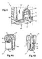
- Fig. 3 shows in an enlarged view of the lower front corner of the partition 7 from Fig. 2 in a not yet fixed to the wire basket bottom 3, prior to attachment of the fastener 9.
- the partition 7 is a plastic molding with a wall plate 10 whose thickness corresponds approximately to the diameter of the wire basket 1 forming wires 11, and along the edge extends on both sides of a peripheral edge bead 12.
- position of the lower edge of the partition wall 7 of the edge bead 12 is interrupted, and instead a circular arc-shaped rib 13 extends into the interior of the plate 10 and around a slot-shaped opening 14 around.
- a flat web 15 is formed with a latching projection 16.
- the latching projection 16 is used for temporary fixing of a bracket 17, which constitutes a part of the fastening element 9.
- This bracket 17 is in FIGS. 4A and 4B shown in two perspective views.
- the bracket 17 comprises two mutually mirror-symmetrical, connected by a semicircular arc 18 flat leg 19, each having a slot-shaped opening 20, surrounded by a torus 21, wear at their free ends.
- a semicircular arc 18 flat leg 19 In two of the annular ring 21 and the opening 20 limited, circular segment-shaped fields each have a detent recess 22 is formed.
- the mutually facing surfaces of the legs 19 each carry a triangular locking projection 23 and of the semicircular arc 18 projects a narrow rib 24 in the space between the legs 19 before.
- the bracket 17 is provided to be slipped from below on one of the wires 11 and a partition wall placed above 7 or 8 of the partitioning device 2. In the attached state, the ribs 24 clamp the wire 11 between them, and the legs 19 completely cover the region of the dividing wall 7 or 8 bounded by the semicircular arcs 18.
- the latch 25 is a one-piece plastic molded part with a head 26 in the form of a circular disk, a cylindrical shaft 27 and a crossbar 28.
- the crossbar 28 carries at its ends the head 26 facing locking lugs 29th
- Fig. 6 shows a perspective view of the front lower corner of the partition 7 with mounted bracket 17 and inserted latch 25.
- the head 26 is at most slightly above the annular bead 21, so that for rotating the bolt 25, a tool such as a Coin or a wrench is needed, which can be inserted into a slot 30 of the head 26.
- Fig. 7 shows in a section along the axis of rotation of the bolt 25, the configuration resulting from that of Fig. 6 by turning the bolt 25 by 90 degrees.
- the ends of the crossbar 28 now extend to the limited by the annular bead 21 fields above and below the opening 20, and the locking lugs 29 are engaged in the locking recesses 22 of the fields.
- the latch 25 is fixed in its orientation; in order to release the locking lugs 29 from the recesses 22, the crossbar 28 and the bracket 17 must be elastically deformed, and the force required for this purpose can again be applied only with the aid of an inserted into the slot 30 tool.
- Fig. 8 shows a section through the mounted on a partition bracket 17 according to a variant Fig. 7 ,
- the bottom 3 comprises two layers of intersecting wires 11. While at Fig. 7 the length of the bracket 17 is dimensioned so that the bracket embrace only a wire 11 of the upper layer and at the same time its openings 20 with the Can overlap opening 14 of the partition wall, the legs of the bracket 17 and in particular the inner ribs 24 are extended so that the bracket is selectively attachable to a wire 11 of the upper or the lower layer. Therefore, one type of bracket suffices to selectively fix a partition wall parallel to the wires 11 of the upper layer or the lower layer.
- one of the legs of the bracket 17 could be shortened and only the other have an opening 20;
- either the head 26 or the cross bar 28 of the (then shortened) bolt 25 would be applied directly to the partition wall 7, 8.
- a latching of the bolt in the blocking position would result in this case in that the latching lugs 25 must pass through the bead surrounding the opening 14, or that a depression corresponding to the recess 22 is formed on the wall plate 11, preferably on both sides.
Landscapes
- Engineering & Computer Science (AREA)
- Mechanical Engineering (AREA)
- General Engineering & Computer Science (AREA)
- Physics & Mathematics (AREA)
- Combustion & Propulsion (AREA)
- Thermal Sciences (AREA)
- Chemical & Material Sciences (AREA)
- Ceramic Engineering (AREA)
- Details Of Rigid Or Semi-Rigid Containers (AREA)
- Refrigerator Housings (AREA)
- Supports For Pipes And Cables (AREA)
- Rigid Containers With Two Or More Constituent Elements (AREA)
- Furniture Connections (AREA)
- Control And Other Processes For Unpacking Of Materials (AREA)
- Crushing And Pulverization Processes (AREA)
Claims (15)
- Récipient (1) doté d'un dispositif de compartimentage servant à compartimenter son espace intérieur, ce dispositif de compartimentage comprenant une paroi de séparation (7, 8) et présentant au moins un étrier (17) muni de deux montants (19), lequel peut être raccordé à une paroi du réservoir, caractérisé en ce que l'étrier (17) peut être emboîté sur un bord de la paroi de séparation (7, 8) avec ses montants (19) s'étendant sur des côtés opposés de la paroi de séparation (7, 8) et en ce que le réservoir (1) présente un verrou (25) qui peut être placé dans des ouvertures (14, 20), alignées les unes par rapport aux autres, de la paroi de séparation (7, 8) et de l'étrier (17).
- Réservoir selon la revendication 1, caractérisé en ce que la paroi (3) du réservoir (1) présente au moins un élément de maintien (11) qui est entouré par l'étrier (17).
- Réservoir selon la revendication 1 ou 2, caractérisé en ce que la paroi est réalisée en tant que fond (3) du réservoir.
- Réservoir selon l'une quelconque des revendications 1 à 3, caractérisé en ce que le réservoir est réalisé en tant que panier en fil (1) et en ce qu'une barre en fil (11) du panier en fil (1) sert d'élément de maintien pour l'au moins un étrier (17).
- Réservoir selon l'une quelconque des revendications 1 à 4, caractérisé en ce que le verrou (25) comprend une tête (26), une traverse (28) et une tige (27) raccordant la tête (26) à la traverse (28), et en ce que le verrou (25), à l'état placé dans les ouvertures (14, 20), peut être tourné entre une orientation de passage, dans laquelle la traverse (28) est capable de traverser les ouvertures (14, 20), et une orientation de blocage, dans laquelle la traverse (28) dépasse au-delà d'un bord des ouvertures (14, 20).
- Réservoir selon la revendication 5, caractérisé en ce que la traverse (28) porte un contour d'enclenchement (29) qui, dans l'orientation de blocage, coopère avec un contour d'enclenchement complémentaire (22) de l'étrier (17) ou de la paroi de séparation en bloquant la rotation du verrou.
- Réservoir selon la revendication 6, caractérisé en ce que le contour d'enclenchement (29) de la traverse (28) est une pointe (29) tournée vers la paroi de séparation (7, 8) et en ce que le contour d'enclenchement complémentaire (22) est un approfondissement.
- Réservoir selon l'une quelconque des revendications 5 à 7, caractérisé en ce que la tête (26) du verrou (25) présente un approfondissement (30) dans lequel un outil peut être introduit pour tourner le verrou (25).
- Réservoir selon l'une quelconque des revendications 5 à 8, caractérisé en ce que dans l'orientation de blocage, la tête (30) et la traverse maintiennent les montants de l'étrier (17) pressés l'un contre l'autre.
- Réservoir selon l'une quelconque des revendications 5 à 8, caractérisé en ce que les deux montants (19) de l'étrier (17) sont symétriques l'un par rapport à l'autre.
- Réservoir selon l'une quelconque des revendications précédentes, caractérisé en ce que la paroi de séparation (7, 8) présente un bourrelet de bordure (12) qui est plus épais que l'écart entre les montants (19) de l'étrier (17) et en ce que le bourrelet de bordure (12) est interrompu de manière respectivement adjacente à une ouverture (14) de la paroi de séparation (7, 8).
- Réservoir selon l'une quelconque des revendications précédentes, caractérisé en ce que la paroi de séparation (7, 8) porte une nervure (13), l'ouverture (14) étant disposée entre la nervure (13) et le bord de la paroi de séparation (7, 8), et en ce que, dans une position, dans laquelle les ouvertures (14, 20) de la paroi de séparation (7, 8) et de l'étrier (17) sont alignées les unes par rapport aux autres, un montant (19) de l'étrier (17) touche la nervure (13).
- Réservoir selon la revendication 10 et la revendication 11, caractérisé en ce que la nervure (13) et le bourrelet de bordure (12) sont raccordés en continu.
- Réservoir selon l'une quelconque des revendications précédentes, caractérisé en ce que l'étrier (17), en position emboîtée, s'enclenche sur la paroi de séparation (7, 8).
- Appareil frigorifique comprenant un récipient selon l'une quelconque des revendications 1 à 14.
Applications Claiming Priority (2)
| Application Number | Priority Date | Filing Date | Title |
|---|---|---|---|
| DE102007021555A DE102007021555A1 (de) | 2007-05-08 | 2007-05-08 | Behälter mit einer Unterteilungsvorrichtung |
| PCT/EP2008/054941 WO2008135391A1 (fr) | 2007-05-08 | 2008-04-23 | Récipient doté d'un dispositif de compartimentage |
Publications (2)
| Publication Number | Publication Date |
|---|---|
| EP2145146A1 EP2145146A1 (fr) | 2010-01-20 |
| EP2145146B1 true EP2145146B1 (fr) | 2010-11-03 |
Family
ID=39564607
Family Applications (1)
| Application Number | Title | Priority Date | Filing Date |
|---|---|---|---|
| EP08736512A Active EP2145146B1 (fr) | 2007-05-08 | 2008-04-23 | Récipient doté d'un dispositif de compartimentage |
Country Status (7)
| Country | Link |
|---|---|
| EP (1) | EP2145146B1 (fr) |
| CN (1) | CN101688749B (fr) |
| AT (1) | ATE487102T1 (fr) |
| DE (2) | DE102007021555A1 (fr) |
| ES (1) | ES2353573T3 (fr) |
| RU (1) | RU2464508C2 (fr) |
| WO (1) | WO2008135391A1 (fr) |
Families Citing this family (13)
| Publication number | Priority date | Publication date | Assignee | Title |
|---|---|---|---|---|
| US20100219147A1 (en) * | 2009-02-27 | 2010-09-02 | Electrolux Home Products, Inc. | Adjustable partition for bottom mount freezer |
| CN102116554A (zh) | 2010-01-04 | 2011-07-06 | Lg电子株式会社 | 电冰箱 |
| US9057555B2 (en) | 2010-02-26 | 2015-06-16 | Electrolux Home Products, Inc. | Tool removable adjustable divider |
| TR201002658A2 (tr) | 2010-04-06 | 2010-12-21 | Vestel Beyaz Eşya Sanayi̇ Ve Ti̇caret Anoni̇m Şi̇rketi̇@ | Bir soğutucu haznesi. |
| CN102530357A (zh) * | 2011-12-31 | 2012-07-04 | 江南大学 | 多组合可变容积的包装箱 |
| GB201404344D0 (en) | 2014-03-12 | 2014-04-23 | Billingham & Co Ltd M | A container assembly |
| EP3277589B1 (fr) * | 2015-04-01 | 2019-05-08 | Ponti, Lorenzo | Système et méthode pour fomer un packet sur mesure |
| PL3163229T3 (pl) * | 2015-11-02 | 2021-01-11 | BSH Hausgeräte GmbH | Urządzenie chłodzące gospodarstwa domowego z indywidualnie wytwarzaną dodatkową przegrodą i sposób wytwarzania dodatkowej przegrody |
| US10948230B2 (en) * | 2015-11-02 | 2021-03-16 | Bsh Hausgeraete Gmbh | Refrigeration appliance having a divided storage space |
| DE102016225086A1 (de) | 2016-12-15 | 2018-06-21 | BSH Hausgeräte GmbH | Anordnung für ein Haushaltskältegerät mit einem Drahtkorb sowie Haushaltskältegerät mit einer derartigen Anordnung |
| DE102017203612A1 (de) * | 2017-03-06 | 2018-09-06 | BSH Hausgeräte GmbH | Kühlgutbehälter |
| CN108266957A (zh) * | 2018-01-05 | 2018-07-10 | 青岛乙顺铁塑制品有限公司 | 一种冰箱搁架及其制造方法 |
| RU207178U1 (ru) * | 2021-07-09 | 2021-10-15 | Публичное акционерное общество «Татнефть» имени В.Д. Шашина | Корзина для переноски манометров |
Family Cites Families (9)
| Publication number | Priority date | Publication date | Assignee | Title |
|---|---|---|---|---|
| US2811277A (en) * | 1956-06-29 | 1957-10-29 | Edward R Gaines | Partitioned receptacle |
| FR2593140B1 (fr) * | 1986-01-23 | 1990-09-14 | Caddie Atel Reunis | Element amovible de separation destine a etre adapte a l'interieur d'une corbeille ou d'un panier en fil metallique. |
| CN2158848Y (zh) * | 1993-05-05 | 1994-03-16 | 尚恺有限公司 | 组合式网架结构 |
| RU2290576C2 (ru) * | 2001-03-13 | 2006-12-27 | Эпплайд Дизайн Энд Инжиниринг Лимитед | Холодильная камера (варианты) |
| CN2603362Y (zh) * | 2003-01-22 | 2004-02-11 | 青岛市家用电器研究所 | 一种新型冷柜 |
| CN2612619Y (zh) * | 2003-03-12 | 2004-04-21 | 李立雄 | 组合式金属框编织产品 |
| KR100679652B1 (ko) * | 2005-08-11 | 2007-02-08 | 엘지전자 주식회사 | 냉장고용 서랍식 도어장치 |
| CN2881480Y (zh) * | 2006-01-18 | 2007-03-21 | 海尔集团公司 | 带有隔板的冰箱抽屉 |
| DE202007013033U1 (de) * | 2007-09-17 | 2008-02-14 | BSH Bosch und Siemens Hausgeräte GmbH | Befestigungsclip (Hakenclip) für Drahtkorbteil |
-
2007
- 2007-05-08 DE DE102007021555A patent/DE102007021555A1/de not_active Withdrawn
-
2008
- 2008-04-23 AT AT08736512T patent/ATE487102T1/de active
- 2008-04-23 WO PCT/EP2008/054941 patent/WO2008135391A1/fr not_active Ceased
- 2008-04-23 ES ES08736512T patent/ES2353573T3/es active Active
- 2008-04-23 EP EP08736512A patent/EP2145146B1/fr active Active
- 2008-04-23 DE DE502008001726T patent/DE502008001726D1/de active Active
- 2008-04-23 CN CN2008800149536A patent/CN101688749B/zh not_active Expired - Fee Related
- 2008-04-23 RU RU2009143630/13A patent/RU2464508C2/ru active
Also Published As
| Publication number | Publication date |
|---|---|
| CN101688749A (zh) | 2010-03-31 |
| DE102007021555A1 (de) | 2008-11-13 |
| RU2009143630A (ru) | 2011-06-20 |
| CN101688749B (zh) | 2012-08-29 |
| WO2008135391A1 (fr) | 2008-11-13 |
| ES2353573T3 (es) | 2011-03-03 |
| DE502008001726D1 (de) | 2010-12-16 |
| EP2145146A1 (fr) | 2010-01-20 |
| RU2464508C2 (ru) | 2012-10-20 |
| ATE487102T1 (de) | 2010-11-15 |
Similar Documents
| Publication | Publication Date | Title |
|---|---|---|
| EP2145146B1 (fr) | Récipient doté d'un dispositif de compartimentage | |
| DE2652138A1 (de) | Einstueckige kunststoffesthaltemutter | |
| WO2006120090A1 (fr) | Appareil menager constitue de plusieurs parties | |
| EP2685111A1 (fr) | Dispositif de serrage de connexion amovibles de deux pièces profilées | |
| DE10233217A1 (de) | Befestigungselement und -anordnung | |
| EP2852768B1 (fr) | Dispositif de fixation | |
| EP1845024B1 (fr) | Dispositif de bras destiné à la division de l'espace intérieur d'un récipient | |
| EP1528878B1 (fr) | Systeme de conservation | |
| WO2009037126A1 (fr) | Dispositif de subdivision et panier grillagé doté de ce dispositif | |
| DE102018101944A1 (de) | Unlösbare Befestigungsvorrichtung | |
| DE3905843C2 (de) | Kassette zum Aufbau von Schubladenschränken | |
| EP0773615A1 (fr) | Armoire de commutation pour installation électrique | |
| EP0116013A2 (fr) | Dispositif à compartiments variables pour tiroirs | |
| EP1661491B1 (fr) | Cadre de support | |
| EP0413396B1 (fr) | Appareil domestique, notamment machine à laver le vaiselle | |
| DE102006059750A1 (de) | Möbelverkettungselement, Möbel und Montageverfahren | |
| DE202014100557U1 (de) | Möbelauszug und Frontblende für einen Möbelauszug | |
| DE19809879C2 (de) | Computergehäuse | |
| DE102006052449A1 (de) | Gehäuse für ein Haushaltsgerät | |
| DE60308631T2 (de) | Verpackung für Fenster- oder Türgriff | |
| DE202018105849U1 (de) | Schnallenaufbau zum Montieren einer Speicher-Leiterplatte | |
| EP1526619A1 (fr) | Armoire électrique avec panneau de couverture inviolable | |
| EP2276985A2 (fr) | Appareil frigorifique doté de compartiments de porte | |
| DE2308121A1 (de) | System zum montieren einer decke | |
| DE202015100519U1 (de) | Objekthalterungssystem |
Legal Events
| Date | Code | Title | Description |
|---|---|---|---|
| PUAI | Public reference made under article 153(3) epc to a published international application that has entered the european phase |
Free format text: ORIGINAL CODE: 0009012 |
|
| 17P | Request for examination filed |
Effective date: 20091208 |
|
| AK | Designated contracting states |
Kind code of ref document: A1 Designated state(s): AT BE BG CH CY CZ DE DK EE ES FI FR GB GR HR HU IE IS IT LI LT LU LV MC MT NL NO PL PT RO SE SI SK TR |
|
| AX | Request for extension of the european patent |
Extension state: AL BA MK RS |
|
| GRAP | Despatch of communication of intention to grant a patent |
Free format text: ORIGINAL CODE: EPIDOSNIGR1 |
|
| DAX | Request for extension of the european patent (deleted) | ||
| GRAS | Grant fee paid |
Free format text: ORIGINAL CODE: EPIDOSNIGR3 |
|
| GRAA | (expected) grant |
Free format text: ORIGINAL CODE: 0009210 |
|
| AK | Designated contracting states |
Kind code of ref document: B1 Designated state(s): AT BE BG CH CY CZ DE DK EE ES FI FR GB GR HR HU IE IS IT LI LT LU LV MC MT NL NO PL PT RO SE SI SK TR |
|
| REG | Reference to a national code |
Ref country code: GB Ref legal event code: FG4D Free format text: NOT ENGLISH |
|
| REG | Reference to a national code |
Ref country code: CH Ref legal event code: EP |
|
| REG | Reference to a national code |
Ref country code: IE Ref legal event code: FG4D Free format text: LANGUAGE OF EP DOCUMENT: GERMAN |
|
| REF | Corresponds to: |
Ref document number: 502008001726 Country of ref document: DE Date of ref document: 20101216 Kind code of ref document: P |
|
| REG | Reference to a national code |
Ref country code: ES Ref legal event code: FG2A Effective date: 20110221 |
|
| REG | Reference to a national code |
Ref country code: NL Ref legal event code: VDEP Effective date: 20101103 |
|
| LTIE | Lt: invalidation of european patent or patent extension |
Effective date: 20101103 |
|
| PG25 | Lapsed in a contracting state [announced via postgrant information from national office to epo] |
Ref country code: NO Free format text: LAPSE BECAUSE OF FAILURE TO SUBMIT A TRANSLATION OF THE DESCRIPTION OR TO PAY THE FEE WITHIN THE PRESCRIBED TIME-LIMIT Effective date: 20110203 Ref country code: LT Free format text: LAPSE BECAUSE OF FAILURE TO SUBMIT A TRANSLATION OF THE DESCRIPTION OR TO PAY THE FEE WITHIN THE PRESCRIBED TIME-LIMIT Effective date: 20101103 |
|
| REG | Reference to a national code |
Ref country code: IE Ref legal event code: FD4D |
|
| PG25 | Lapsed in a contracting state [announced via postgrant information from national office to epo] |
Ref country code: PT Free format text: LAPSE BECAUSE OF FAILURE TO SUBMIT A TRANSLATION OF THE DESCRIPTION OR TO PAY THE FEE WITHIN THE PRESCRIBED TIME-LIMIT Effective date: 20110303 Ref country code: SE Free format text: LAPSE BECAUSE OF FAILURE TO SUBMIT A TRANSLATION OF THE DESCRIPTION OR TO PAY THE FEE WITHIN THE PRESCRIBED TIME-LIMIT Effective date: 20101103 Ref country code: LV Free format text: LAPSE BECAUSE OF FAILURE TO SUBMIT A TRANSLATION OF THE DESCRIPTION OR TO PAY THE FEE WITHIN THE PRESCRIBED TIME-LIMIT Effective date: 20101103 Ref country code: BG Free format text: LAPSE BECAUSE OF FAILURE TO SUBMIT A TRANSLATION OF THE DESCRIPTION OR TO PAY THE FEE WITHIN THE PRESCRIBED TIME-LIMIT Effective date: 20110203 Ref country code: NL Free format text: LAPSE BECAUSE OF FAILURE TO SUBMIT A TRANSLATION OF THE DESCRIPTION OR TO PAY THE FEE WITHIN THE PRESCRIBED TIME-LIMIT Effective date: 20101103 Ref country code: SI Free format text: LAPSE BECAUSE OF FAILURE TO SUBMIT A TRANSLATION OF THE DESCRIPTION OR TO PAY THE FEE WITHIN THE PRESCRIBED TIME-LIMIT Effective date: 20101103 Ref country code: HR Free format text: LAPSE BECAUSE OF FAILURE TO SUBMIT A TRANSLATION OF THE DESCRIPTION OR TO PAY THE FEE WITHIN THE PRESCRIBED TIME-LIMIT Effective date: 20101103 Ref country code: FI Free format text: LAPSE BECAUSE OF FAILURE TO SUBMIT A TRANSLATION OF THE DESCRIPTION OR TO PAY THE FEE WITHIN THE PRESCRIBED TIME-LIMIT Effective date: 20101103 Ref country code: IS Free format text: LAPSE BECAUSE OF FAILURE TO SUBMIT A TRANSLATION OF THE DESCRIPTION OR TO PAY THE FEE WITHIN THE PRESCRIBED TIME-LIMIT Effective date: 20110303 |
|
| PG25 | Lapsed in a contracting state [announced via postgrant information from national office to epo] |
Ref country code: GR Free format text: LAPSE BECAUSE OF FAILURE TO SUBMIT A TRANSLATION OF THE DESCRIPTION OR TO PAY THE FEE WITHIN THE PRESCRIBED TIME-LIMIT Effective date: 20110204 |
|
| PG25 | Lapsed in a contracting state [announced via postgrant information from national office to epo] |
Ref country code: CZ Free format text: LAPSE BECAUSE OF FAILURE TO SUBMIT A TRANSLATION OF THE DESCRIPTION OR TO PAY THE FEE WITHIN THE PRESCRIBED TIME-LIMIT Effective date: 20101103 Ref country code: EE Free format text: LAPSE BECAUSE OF FAILURE TO SUBMIT A TRANSLATION OF THE DESCRIPTION OR TO PAY THE FEE WITHIN THE PRESCRIBED TIME-LIMIT Effective date: 20101103 Ref country code: IE Free format text: LAPSE BECAUSE OF FAILURE TO SUBMIT A TRANSLATION OF THE DESCRIPTION OR TO PAY THE FEE WITHIN THE PRESCRIBED TIME-LIMIT Effective date: 20101103 |
|
| PG25 | Lapsed in a contracting state [announced via postgrant information from national office to epo] |
Ref country code: DK Free format text: LAPSE BECAUSE OF FAILURE TO SUBMIT A TRANSLATION OF THE DESCRIPTION OR TO PAY THE FEE WITHIN THE PRESCRIBED TIME-LIMIT Effective date: 20101103 Ref country code: SK Free format text: LAPSE BECAUSE OF FAILURE TO SUBMIT A TRANSLATION OF THE DESCRIPTION OR TO PAY THE FEE WITHIN THE PRESCRIBED TIME-LIMIT Effective date: 20101103 Ref country code: RO Free format text: LAPSE BECAUSE OF FAILURE TO SUBMIT A TRANSLATION OF THE DESCRIPTION OR TO PAY THE FEE WITHIN THE PRESCRIBED TIME-LIMIT Effective date: 20101103 Ref country code: PL Free format text: LAPSE BECAUSE OF FAILURE TO SUBMIT A TRANSLATION OF THE DESCRIPTION OR TO PAY THE FEE WITHIN THE PRESCRIBED TIME-LIMIT Effective date: 20101103 |
|
| PLBE | No opposition filed within time limit |
Free format text: ORIGINAL CODE: 0009261 |
|
| STAA | Information on the status of an ep patent application or granted ep patent |
Free format text: STATUS: NO OPPOSITION FILED WITHIN TIME LIMIT |
|
| 26N | No opposition filed |
Effective date: 20110804 |
|
| BERE | Be: lapsed |
Owner name: BSH BOSCH UND SIEMENS HAUSGERATE G.M.B.H. Effective date: 20110430 Owner name: MIELE & CIE. K.G. Effective date: 20110430 |
|
| PG25 | Lapsed in a contracting state [announced via postgrant information from national office to epo] |
Ref country code: MC Free format text: LAPSE BECAUSE OF NON-PAYMENT OF DUE FEES Effective date: 20110430 |
|
| REG | Reference to a national code |
Ref country code: DE Ref legal event code: R097 Ref document number: 502008001726 Country of ref document: DE Effective date: 20110804 |
|
| PG25 | Lapsed in a contracting state [announced via postgrant information from national office to epo] |
Ref country code: MT Free format text: LAPSE BECAUSE OF FAILURE TO SUBMIT A TRANSLATION OF THE DESCRIPTION OR TO PAY THE FEE WITHIN THE PRESCRIBED TIME-LIMIT Effective date: 20101103 |
|
| PG25 | Lapsed in a contracting state [announced via postgrant information from national office to epo] |
Ref country code: BE Free format text: LAPSE BECAUSE OF NON-PAYMENT OF DUE FEES Effective date: 20110430 |
|
| REG | Reference to a national code |
Ref country code: CH Ref legal event code: PL |
|
| PG25 | Lapsed in a contracting state [announced via postgrant information from national office to epo] |
Ref country code: LI Free format text: LAPSE BECAUSE OF NON-PAYMENT OF DUE FEES Effective date: 20120430 Ref country code: CH Free format text: LAPSE BECAUSE OF NON-PAYMENT OF DUE FEES Effective date: 20120430 |
|
| PG25 | Lapsed in a contracting state [announced via postgrant information from national office to epo] |
Ref country code: CY Free format text: LAPSE BECAUSE OF EXPIRATION OF PROTECTION Effective date: 20101103 Ref country code: LU Free format text: LAPSE BECAUSE OF NON-PAYMENT OF DUE FEES Effective date: 20110423 |
|
| PG25 | Lapsed in a contracting state [announced via postgrant information from national office to epo] |
Ref country code: HU Free format text: LAPSE BECAUSE OF FAILURE TO SUBMIT A TRANSLATION OF THE DESCRIPTION OR TO PAY THE FEE WITHIN THE PRESCRIBED TIME-LIMIT Effective date: 20101103 |
|
| REG | Reference to a national code |
Ref country code: AT Ref legal event code: MM01 Ref document number: 487102 Country of ref document: AT Kind code of ref document: T Effective date: 20130423 |
|
| PG25 | Lapsed in a contracting state [announced via postgrant information from national office to epo] |
Ref country code: AT Free format text: LAPSE BECAUSE OF NON-PAYMENT OF DUE FEES Effective date: 20130423 |
|
| REG | Reference to a national code |
Ref country code: FR Ref legal event code: PLFP Year of fee payment: 8 |
|
| REG | Reference to a national code |
Ref country code: DE Ref legal event code: R081 Ref document number: 502008001726 Country of ref document: DE Owner name: BSH HAUSGERAETE GMBH, DE Free format text: FORMER OWNER: BSH BOSCH UND SIEMENS HAUSGERAET, MIELE & CIE. KG, , DE Effective date: 20150414 Ref country code: DE Ref legal event code: R081 Ref document number: 502008001726 Country of ref document: DE Owner name: MIELE & CIE. KG, DE Free format text: FORMER OWNER: BSH BOSCH UND SIEMENS HAUSGERAET, MIELE & CIE. KG, , DE Effective date: 20150414 Ref country code: DE Ref legal event code: R081 Ref document number: 502008001726 Country of ref document: DE Owner name: MIELE & CIE. KG, DE Free format text: FORMER OWNERS: BSH BOSCH UND SIEMENS HAUSGERAETE GMBH, 81739 MUENCHEN, DE; MIELE & CIE. KG, 33332 GUETERSLOH, DE Effective date: 20150414 Ref country code: DE Ref legal event code: R081 Ref document number: 502008001726 Country of ref document: DE Owner name: BSH HAUSGERAETE GMBH, DE Free format text: FORMER OWNERS: BSH BOSCH UND SIEMENS HAUSGERAETE GMBH, 81739 MUENCHEN, DE; MIELE & CIE. KG, 33332 GUETERSLOH, DE Effective date: 20150414 |
|
| REG | Reference to a national code |
Ref country code: ES Ref legal event code: PC2A Owner name: BSH HAUSGERATE GMBH Effective date: 20150529 |
|
| REG | Reference to a national code |
Ref country code: FR Ref legal event code: CD Owner name: MIELE & CIE. KG, DE Effective date: 20151022 Ref country code: FR Ref legal event code: CD Owner name: BSH HAUSGERATE GMBH, DE Effective date: 20151022 |
|
| REG | Reference to a national code |
Ref country code: FR Ref legal event code: PLFP Year of fee payment: 9 |
|
| REG | Reference to a national code |
Ref country code: FR Ref legal event code: PLFP Year of fee payment: 10 |
|
| PGFP | Annual fee paid to national office [announced via postgrant information from national office to epo] |
Ref country code: GB Payment date: 20170425 Year of fee payment: 10 Ref country code: FR Payment date: 20170424 Year of fee payment: 10 |
|
| PGFP | Annual fee paid to national office [announced via postgrant information from national office to epo] |
Ref country code: ES Payment date: 20170503 Year of fee payment: 10 |
|
| GBPC | Gb: european patent ceased through non-payment of renewal fee |
Effective date: 20180423 |
|
| PG25 | Lapsed in a contracting state [announced via postgrant information from national office to epo] |
Ref country code: GB Free format text: LAPSE BECAUSE OF NON-PAYMENT OF DUE FEES Effective date: 20180423 |
|
| PG25 | Lapsed in a contracting state [announced via postgrant information from national office to epo] |
Ref country code: FR Free format text: LAPSE BECAUSE OF NON-PAYMENT OF DUE FEES Effective date: 20180430 |
|
| REG | Reference to a national code |
Ref country code: ES Ref legal event code: FD2A Effective date: 20190912 |
|
| PG25 | Lapsed in a contracting state [announced via postgrant information from national office to epo] |
Ref country code: ES Free format text: LAPSE BECAUSE OF NON-PAYMENT OF DUE FEES Effective date: 20180424 |
|
| PGFP | Annual fee paid to national office [announced via postgrant information from national office to epo] |
Ref country code: IT Payment date: 20220429 Year of fee payment: 15 |
|
| PGFP | Annual fee paid to national office [announced via postgrant information from national office to epo] |
Ref country code: DE Payment date: 20230430 Year of fee payment: 16 |
|
| PGFP | Annual fee paid to national office [announced via postgrant information from national office to epo] |
Ref country code: TR Payment date: 20230418 Year of fee payment: 16 |
|
| PG25 | Lapsed in a contracting state [announced via postgrant information from national office to epo] |
Ref country code: IT Free format text: LAPSE BECAUSE OF NON-PAYMENT OF DUE FEES Effective date: 20230423 |
|
| REG | Reference to a national code |
Ref country code: DE Ref legal event code: R119 Ref document number: 502008001726 Country of ref document: DE |
|
| PG25 | Lapsed in a contracting state [announced via postgrant information from national office to epo] |
Ref country code: DE Free format text: LAPSE BECAUSE OF NON-PAYMENT OF DUE FEES Effective date: 20241105 |
|
| PG25 | Lapsed in a contracting state [announced via postgrant information from national office to epo] |
Ref country code: DE Free format text: LAPSE BECAUSE OF NON-PAYMENT OF DUE FEES Effective date: 20241105 |