EP2146202B1 - Procédé pour détecter un défaut de surface inégale - Google Patents
Procédé pour détecter un défaut de surface inégale Download PDFInfo
- Publication number
- EP2146202B1 EP2146202B1 EP08792747.1A EP08792747A EP2146202B1 EP 2146202 B1 EP2146202 B1 EP 2146202B1 EP 08792747 A EP08792747 A EP 08792747A EP 2146202 B1 EP2146202 B1 EP 2146202B1
- Authority
- EP
- European Patent Office
- Prior art keywords
- steel
- magnetic flux
- defects
- concavo
- defect
- Prior art date
- Legal status (The legal status is an assumption and is not a legal conclusion. Google has not performed a legal analysis and makes no representation as to the accuracy of the status listed.)
- Active
Links
Images






Classifications
-
- G—PHYSICS
- G01—MEASURING; TESTING
- G01N—INVESTIGATING OR ANALYSING MATERIALS BY DETERMINING THEIR CHEMICAL OR PHYSICAL PROPERTIES
- G01N27/00—Investigating or analysing materials by the use of electric, electrochemical, or magnetic means
- G01N27/72—Investigating or analysing materials by the use of electric, electrochemical, or magnetic means by investigating magnetic variables
- G01N27/82—Investigating or analysing materials by the use of electric, electrochemical, or magnetic means by investigating magnetic variables for investigating the presence of flaws
-
- G—PHYSICS
- G01—MEASURING; TESTING
- G01B—MEASURING LENGTH, THICKNESS OR SIMILAR LINEAR DIMENSIONS; MEASURING ANGLES; MEASURING AREAS; MEASURING IRREGULARITIES OF SURFACES OR CONTOURS
- G01B7/00—Measuring arrangements characterised by the use of electric or magnetic techniques
- G01B7/34—Measuring arrangements characterised by the use of electric or magnetic techniques for measuring roughness or irregularity of surfaces
-
- G—PHYSICS
- G01—MEASURING; TESTING
- G01N—INVESTIGATING OR ANALYSING MATERIALS BY DETERMINING THEIR CHEMICAL OR PHYSICAL PROPERTIES
- G01N27/00—Investigating or analysing materials by the use of electric, electrochemical, or magnetic means
- G01N27/72—Investigating or analysing materials by the use of electric, electrochemical, or magnetic means by investigating magnetic variables
- G01N27/82—Investigating or analysing materials by the use of electric, electrochemical, or magnetic means by investigating magnetic variables for investigating the presence of flaws
- G01N27/83—Investigating or analysing materials by the use of electric, electrochemical, or magnetic means by investigating magnetic variables for investigating the presence of flaws by investigating stray magnetic fields
Definitions
- the present invention relates to a detection method for detecting concavo-convex shape surface defects existing on steel, and in particular to a method for detecting concavo-convex shape surface defects, wherein the concavo-convex shape surface defects each have a concavo-convex level in the range of 0.5 to 6 ⁇ m and an area of 10 mm 2 or larger and exist on a rough surface, with Ra being in the range of 0.5 to 2 ⁇ m, of a steel sheet having a thickness in the range of 0.4 to 2.3 mm.
- FIG. 4 is a schematic diagram of a cross-section of a fine concavo-convex shape surface defect. The size of each fine concavo-convex shape surface defect is approximately in the range of 10 to 1000 mm 2 in area, but is 5 ⁇ m or lower in concavo-convex level as described above. The lowest concavo-convex level is approximately 1 ⁇ m, which is very small and is of the same order as the surface roughness.
- the shape of fine concavo-convex shape surface defects includes point flaws like roll-generated flaws described earlier and flaws extending in the longitudinal direction of a steel sheet, such as linear marks or buckling marks.
- Patent Document 2 is intended for steel sheets, but still cannot be applied to objects other than materials having a mirror surface such as stainless steel sheets. Furthermore, this technique is admittedly effective in detecting concavo-convex defects extending perpendicular to the illumination detection, but is insufficient in terms of detection sensitivity for those extending parallel to the illumination detection.
- Patent Document 4 The technique disclosed in Patent Document 4 was developed to address this situation, and accordingly an apparatus for this technique has very high detection sensitivity.
- this technique requires an angle of incidence as large as close to 90°, thereby making it difficult to introduce a necessary apparatus into an actual operation line. It has also the problem that adjustment of optics is difficult.
- the intensity of signals for this magnetic flux leakage inspection corresponds to the shape change level of surface defects (concavo-convex change level), and thus the lowest shape change level of surface defects (concavo-convex change level) detectable in an automatic inspection is limited.
- this lower limit to be approximately 100 ⁇ m (Non-patent Document 1).
- Non-patent Document 1 it is recognized that stable detection of surface defects having a shape change level of approximately 100 ⁇ m or lower is difficult and signals generated by changes in the shape of approximately 100 ⁇ m or lower serve only as noise sources observed in flaw detection for other purposes (e.g., detection of inclusions).
- the lowest detectable size of an inclusion in a steel sheet discussed in the present invention whose maximum thickness is 2.3 mm, would probably be much larger than 10 ⁇ m (size in the direction of the steel sheet thickness) if they can be detected at all, considering the fact that this inclusion detector is intended for thinner steel sheets used for cans.
- Non-patent Document 6 discloses the results of explorative research on the detection of whetstone-inspection-level flaws conducted by WG for research on cold rolling in rolling, refining, and temper systems, Iron and Steel Technology Committee, the Japan Iron and Steel Federation from September 1994 to July 1995 (Report of Explorative Research on Seed Technology for Detection of Whetstone-inspection-level Flaws ).
- Previous approaches to automatic inspections of fine concavo-convex shape surface defects, the target of the present invention were mainly based on a light-detecting method, and, to date, there have been no approaches using a magnetic flux leakage inspection method.
- JP 2001 296277 A JP 2004 354240 A , JP 3 892801 B2 and JP 2004 191220 A , JP 2005 061940 A and US 2002/121896 A1 , all of which relate to magnetic detection/sensing technologies.
- the present invention is defined by the appended independent method claim 1, the dependent claims are directed to optional features and preferred embodiments, and provides a practical method for stable detection of concavo-convex shape surface defects that exist on a test object having a surface roughness Ra approximately in the range of 0.5 to 2 ⁇ m, wherein the concavo-convex shape surface defects are usually almost invisible and detectable only by whetstone inspection, are difficult to detect by automatic detection, and each have a concavo-convex level on the order of a few micrometers.
- the present invention allows for stable detection of fine concavo-convex shape surface defects that exist on a test object having considerable surface roughness, wherein the fine concavo-convex shape surface defects are usually almost invisible to the naked eye and detectable only by whetstone inspection, are difficult to detect in automatic detection, and each have a concavo-convex level on the order of a few micrometers and a smooth outline.
- the inventors To measure fine concavo-convex shape surface defects generated during rolling (roll-generated fine concavo-convex shape surface defects), i.e., the target of the present invention, the inventors first conducted X-ray diffraction analysis of such defects in some sheets to determine the physical characteristics of the defects. As a result, it was found that these fine concavo-convex shape surface defects had strain that probably emerged during transfer of flaws from the roll in the process of defect formation.
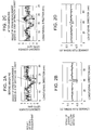
- FIGs. 2 are diagrams showing example results of magnetic flux leakage inspection and shape measurement obtained before and after annealing.
- FIGs. 2 had a concavo-convex level of 5 ⁇ m, which was slightly larger than the minimum detectable size of a fine concavo-convex shape surface defect.
- FIGs. 2A and 2B represent the state before annealing
- FIGs. 2C and 2D represent the state after annealing.
- FIGs. 2A and 2C represent the shape distribution in the longitudinal direction (traveling direction)
- FIGs. 2B and 2D represent the values of signals sensed by the magnetic flux leakage inspection apparatus in the longitudinal direction (traveling direction).
- the strain level measured using X-ray diffraction decreased from 0.00217 to 0.00067 during annealing. The results shown in FIGs.
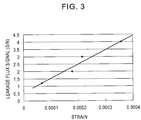
- FIG. 3 is a diagram showing the relationship between strain and leakage flux, which was obtained by plotting the strain measured using X-ray diffraction in some roll-generated fine concavo-convex shape surface defects whose concavo-convex levels were almost identical against the results of magnetic flux leakage inspection.
- FIG. 3 demonstrates the strong relationship between the strain and the leakage flux signals, and this result also shows that the strain can be detected using leakage flux.
- strain generates leakage flux signals, and this is probably because strain changes the crystal lattice interval in the sample and accordingly changes the interaction between spins, thereby changing the magnetic characteristics of the sample.
- a usual magnetic flux leakage inspection method generally uses a saturated magnetic flux for measurement to improve the signal intensity and remove the influence of noise generated by unevenness of magnetic characteristics (magnetic permeability) of the test object.
- comparing the signal component attributed to concaves and convexes with that attributed to strain enables comparing of the concavo-convex level and the strain level, thereby making it possible to identify which roll causes defects by, for example, assuming that the combination of a low concavo-convex level and large strain represents a defect caused by a roll used at a high rolling reduction.
- FIG. 9 is a diagram showing Example Relationship 1 between the lift-off and S/N
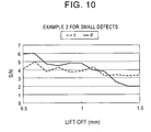
- FIG. 10 is a diagram showing Example Relationship 2 between the lift-off and S/N.
- Each of these drawings is a graph made for the purpose of studying the relationship between the lift-off and S/N.
- FIG. 9 shows the results obtained by measuring the following sample defects each having a relatively small concavo-convex level of a few micrometers and a large area, the main target of detection according to the present invention, using different lift-offs: Sample a: 15 mm in length, 4 mm in width; Sample b: 10 mm in length, 4 mm in width.
- FIG. 9 shows the results obtained by measuring the following sample defects each having a relatively small concavo-convex level of a few micrometers and a large area, the main target of detection according to the present invention, using different lift-offs: Sample a: 15 mm in length, 4 mm in width; Sample b: 10 mm in length, 4 mm
- Sample 10 shows the results obtained by measuring the following sample defects each having a relatively large concavo-convex level of a few tens of micrometers and a small area: Sample c: 1 mm in length, 2 mm in width; Sample d: 1 mm in length, 2 mm in width.
- a hall element with the area of magnetism-sensing portion being approximately 0.2 mm or smaller in diameter was used as the sensor.
- a lift-off in the range of 0.5 to 1.5 mm gave S/N of 2 or higher and thus is sufficient to be used for detection; however, considering the long and short dashed line representing S/N of 3, the level allowing for automatic detection, a preferred lift-off range for automatic detection is 0.8 to 1.2 mm.
- a lift-off of 1 mm gave especially high S/N and this suggests that the most preferred lift-off range is 0.9 to 1.1 mm.
- FIGs. 11 are schematic diagrams showing the situations of measurement of small defects (corresponding to the defects c and d described above) and large defects (corresponding to the defects a and b described above).
- a defect difficult to detect is one having small concaves and convexes and a small area.
- Such a defect is inherently smaller than the detection area of a sensor, and thus the area of the defect encompassed in the detection area of the sensor decreases as the lift-off is increased (see FIG. 11A ).
- signals existing in the detection area are averaged during detection, and thus the defect signals are averaged together with signals coming from the surrounding normal portion (background noise signals). Therefore, the signal intensity is further lowered.
- signals coming from such a normal portion have almost identical intensities, and thus a decrease in these signals is smaller than that in defect signals.
- FIG. 13 is a diagram showing the relationship between the size of the defects shown in FIG. 12A in the thickness direction and S/N of leakage flux signals.
- S/N of leakage flux signals is 2 or higher for all defects, and this demonstrates that the present invention has a sufficient detection sensitivity.
- four sample defects having a size in the concavo-convex direction (concavo-convex change level) of 0.5 ⁇ m showed S/N of approximately 3 and thus the data points for these defects are plotted overlapping each other.
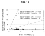
- FIG. 14 is a diagram showing the relationship between the size of defects in the thickness direction and the thickness of the test steel sheets.
- the data points measured according to the present invention and shown in FIGs. 12 and 13 are represented by O, and those measured using a known magnetic flux leakage inspection method using a magnetic flux leakage inspection apparatus for steel sheets installed in a line after a cold rolling process are represented by x.
- x those measured using a known magnetic flux leakage inspection method using a magnetic flux leakage inspection apparatus for steel sheets installed in a line after a cold rolling process.
- the present invention handles fine concavo-convex shape surface defects existing on a steel sheet with a thickness in the range of 0.4 to 2.3 mm and each having a concavo-convex level of 0.5 to 6 ⁇ m and, in the present invention, the value s/t obtained by dividing the size of a defect in the direction of steel sheet thickness s (concavo-convex change level; unit: ⁇ m) by the thickness of a test sheet t (mm) is extremely small and in the range of 0.63 to 9.0 as can be seen in FIG. 15 .
- the target of inspection according to the present invention is fine concavo-convex shape surface defects having s/t, the ratio of the size of a defect in the direction of steel sheet thickness s ( ⁇ m) to the steel sheet thickness (mm), in the range of 0.63 to 9.0.
Landscapes
- Physics & Mathematics (AREA)
- General Physics & Mathematics (AREA)
- Chemical & Material Sciences (AREA)
- Chemical Kinetics & Catalysis (AREA)
- Electrochemistry (AREA)
- Health & Medical Sciences (AREA)
- Life Sciences & Earth Sciences (AREA)
- Analytical Chemistry (AREA)
- Biochemistry (AREA)
- General Health & Medical Sciences (AREA)
- Immunology (AREA)
- Pathology (AREA)
- Investigating Or Analyzing Materials By The Use Of Magnetic Means (AREA)
- Measurement Of Length, Angles, Or The Like Using Electric Or Magnetic Means (AREA)
Claims (9)
- Procédé de détection pour détecter un défaut de surface de forme concavo-convexe existant sur un acier ayant une rugosité de surface Ra dans la plage de 0,5 à 2 µm comprenant
l'application d'un flux magnétique à l'acier de sorte qu'une densité de flux magnétique de l'acier sur lequel le flux magnétique est appliqué est d'au moins 75 % et inférieure à 95 % de la densité de flux magnétique à saturation magnétique ;
une étape de détection d'un signal attribué à une déformation du défaut de surface de forme concavo-convexe ayant une taille dans une plage de 0,5 à 6 µm, dans lequel le signal est un flux magnétique fuyant de l'acier sur lequel le flux magnétique est appliqué, et une distance entre l'acier et un appareil de détection qui détecte le signal est dans une plage de 0,5 à 1,5 mm ; et
une étape de détermination d'un point qui correspond au signal ayant une intensité supérieure ou égale à une valeur seuil pour être un défaut. - Procédé de détection selon la revendication 1, dans lequel
une épaisseur de l'acier est dans une plage de 0,4 à 2,3 mm. - Procédé de détection selon la revendication 1, dans lequel
un rapport s/t d'une taille du défaut de surface de forme concavo-convexe dans une direction d'une épaisseur s (µm) à l'épaisseur de l'acier t (mm) est dans une plage de 0,63 à 9,0. - Procédé de détection selon la revendication 1, dans lequel
la détection est réalisée dans des conditions combinées incluant une condition dans laquelle la densité de flux magnétique de l'acier sur lequel le flux magnétique est appliqué est d'au moins 75 % et inférieure à 95 % de la densité de flux magnétique à saturation magnétique et une autre condition dans laquelle elle est d'au moins 95 % de la densité de flux magnétique à saturation magnétique. - Procédé de détection selon la revendication 1, dans lequel
une intensité d'un champ magnétique appliqué à l'acier est d'au moins 4 000 A/m et de moins de 25 000 A/m. - Procédé de détection selon la revendication 1, dans lequel
la détection est réalisée dans une condition combinée obtenue par combinaison d'une condition dans laquelle l'intensité d'un champ magnétique appliqué à l'acier est d'au moins 4 000 A/m et de moins de 25 000 A/m et une autre condition dans laquelle elle est d'au moins 25 000 A/m. - Procédé de détection selon l'une quelconque des revendications 1 à 6, dans lequel
le signal est une quantité physique attribuée à une déformation du défaut de surface de forme concavo-convexe ayant lieu dans un procédé qui est un procédé en aval du laminage, qui est une cause du défaut, et est également un procédé an amont d'un procédé produisant un effet de recuit. - Procédé de détection selon l'une quelconque des revendications 1 à 6, dans lequel
le signal est une quantité physique attribuée à une déformation du défaut de surface de forme concavo-convexe ayant lieu dans un procédé qui est un procédé en aval du laminage, qui est une cause du défaut, et se produit plus tard que le dressage par laminage à froid. - Procédé de fabrication pour fabriquer un acier comprenant le procédé de détection selon l'une quelconque des revendications 1 à 8.
Applications Claiming Priority (2)
| Application Number | Priority Date | Filing Date | Title |
|---|---|---|---|
| JP2007217180A JP5186837B2 (ja) | 2007-08-23 | 2007-08-23 | 微小凹凸表面欠陥の検出方法及び装置 |
| PCT/JP2008/065221 WO2009025384A1 (fr) | 2007-08-23 | 2008-08-20 | Procédé et appareil pour détecter un défaut de surface inégale |
Publications (3)
| Publication Number | Publication Date |
|---|---|
| EP2146202A1 EP2146202A1 (fr) | 2010-01-20 |
| EP2146202A4 EP2146202A4 (fr) | 2017-01-18 |
| EP2146202B1 true EP2146202B1 (fr) | 2019-09-18 |
Family
ID=40378282
Family Applications (1)
| Application Number | Title | Priority Date | Filing Date |
|---|---|---|---|
| EP08792747.1A Active EP2146202B1 (fr) | 2007-08-23 | 2008-08-20 | Procédé pour détecter un défaut de surface inégale |
Country Status (7)
| Country | Link |
|---|---|
| US (1) | US8466673B2 (fr) |
| EP (1) | EP2146202B1 (fr) |
| JP (1) | JP5186837B2 (fr) |
| KR (2) | KR101255412B1 (fr) |
| CN (1) | CN101688851B (fr) |
| TW (1) | TWI480546B (fr) |
| WO (1) | WO2009025384A1 (fr) |
Families Citing this family (23)
| Publication number | Priority date | Publication date | Assignee | Title |
|---|---|---|---|---|
| JP5003351B2 (ja) * | 2007-08-23 | 2012-08-15 | Jfeスチール株式会社 | 磁性金属帯の微小表面欠陥の品質検査方法及び装置 |
| TWI439947B (zh) * | 2010-11-11 | 2014-06-01 | Ind Tech Res Inst | 辨識人體移動行為之方法及系統 |
| US10175200B2 (en) * | 2014-05-30 | 2019-01-08 | Prime Photonics, Lc | Methods and systems for detecting nonuniformities in a material, component, or structure |
| JP6179482B2 (ja) * | 2014-08-08 | 2017-08-16 | Jfeスチール株式会社 | 微小凹凸表面欠陥の検出方法及び検出装置 |
| CN104112563B (zh) * | 2014-08-13 | 2016-06-01 | 爱德森(厦门)电子有限公司 | 一种交流恒磁源的设计与使用方法 |
| CN104266619B (zh) * | 2014-09-12 | 2017-05-17 | 首钢总公司 | 一种测定热镀锌钢板表面锌渣位置及密度分布的方法 |
| CN104458894B (zh) * | 2014-12-08 | 2017-06-06 | 国家电网公司 | 高速水轮发电机转子磁极磁轭t尾槽的检测方法及其装置 |
| JP6441094B2 (ja) * | 2015-01-27 | 2018-12-19 | 国立大学法人東京農工大学 | 電磁鋼板の物性評価装置、その評価方法、並びに電磁鋼板の製造システム及び電磁鋼板の製造方法 |
| JP6063097B1 (ja) * | 2015-03-23 | 2017-01-18 | 中国電力株式会社 | 接着性分子 |
| JP6514592B2 (ja) * | 2015-07-16 | 2019-05-15 | 住友化学株式会社 | 欠陥測定方法、欠陥測定装置および検査プローブ |
| CN105203012A (zh) * | 2015-10-12 | 2015-12-30 | 无锡乐尔科技有限公司 | 一种磁性厚度传感器 |
| CN105526851B (zh) * | 2016-01-25 | 2018-04-20 | 广州文冲船厂有限责任公司 | 一种麻点面积检测器及检测方法 |
| CN106290552B (zh) * | 2016-08-01 | 2019-09-13 | 四川大学 | 一种基于旋转磁化场的钢板漏磁检测装置 |
| CN106585100B (zh) * | 2016-12-20 | 2018-05-08 | 武汉钢铁有限公司 | 带材表面缺陷喷涂标识设备 |
| CN106907992A (zh) * | 2017-03-01 | 2017-06-30 | 米艾德智能科技(苏州)有限公司 | 一种贴片检测系统及检测方法 |
| ES3040734T3 (en) * | 2017-10-06 | 2025-11-04 | Rosen Ip Ag | Method for determining the geometry of a defect and for determining a load capacity limit |
| TWI663395B (zh) * | 2018-11-02 | 2019-06-21 | 中國鋼鐵股份有限公司 | Steel strip crease detection method |
| CN110108784A (zh) * | 2019-06-03 | 2019-08-09 | 中国计量大学 | 一种基于低频漏磁的焊缝检测便携式笔 |
| JP6908212B1 (ja) * | 2019-12-20 | 2021-07-21 | Jfeスチール株式会社 | 漏洩磁気検査装置および欠陥検査方法 |
| TWI911233B (zh) | 2020-06-18 | 2026-01-11 | 泰商榮龍工程設備服務有限公司 | 一用於偵測一表面之不平整度之感測器模組,一具有該模組之裝置,以及一使用該感測器模組,以偵測一表面其不平整度之方法 |
| CN112986526B (zh) * | 2021-02-09 | 2024-01-09 | 鞍钢股份有限公司 | 一种钢坯表面缺陷自动检查装置及方法 |
| CN113376350B (zh) * | 2021-08-14 | 2021-10-26 | 湖南博之凯创新科技有限公司 | 一种工程机械覆盖件的曲面缺陷检测工具 |
| CN117109481B (zh) * | 2023-07-28 | 2024-12-24 | 中国水利水电第五工程局有限公司 | 一种过流面混凝土整体平整度及过流能力检测评价方法 |
Family Cites Families (19)
| Publication number | Priority date | Publication date | Assignee | Title |
|---|---|---|---|---|
| US2814019A (en) * | 1951-10-03 | 1957-11-19 | Houston Oil Field Mat Co Inc | Magnetic method of detecting stress and strain in ferrous material |
| US3535625A (en) * | 1968-04-22 | 1970-10-20 | Garrett Corp | Strain and flaw detector |
| JPS5886408A (ja) | 1981-11-18 | 1983-05-24 | Matsushita Electric Ind Co Ltd | 鏡面の微小凹凸または歪検査装置 |
| JPH05256630A (ja) | 1992-03-11 | 1993-10-05 | Nippon Steel Corp | 鋼板の表面凹凸縞検査装置 |
| JPH08160006A (ja) | 1994-11-30 | 1996-06-21 | Kawasaki Steel Corp | 鋼板の欠陥検出方法 |
| JP2000298102A (ja) | 1999-02-08 | 2000-10-24 | Nkk Corp | 表面検査装置 |
| JP3271246B2 (ja) * | 1999-02-08 | 2002-04-02 | 日本鋼管株式会社 | 漏洩磁束探傷法及び漏洩磁束探傷装置並びに製鉄プラント |
| JP3690580B2 (ja) * | 2000-04-13 | 2005-08-31 | Jfeスチール株式会社 | 磁気探傷方法 |
| KR100487737B1 (ko) * | 2000-07-12 | 2005-05-03 | 제이에프이 스틸 가부시키가이샤 | 누설자속 탐상법 및 그 것을 이용한 열연강판의 제조방법 |
| JP3824059B2 (ja) * | 2000-08-03 | 2006-09-20 | Jfeスチール株式会社 | 表面検査装置及び微小凹凸欠陥の無い鋼板の製造方法 |
| JP3811039B2 (ja) * | 2000-10-18 | 2006-08-16 | Jfeスチール株式会社 | 磁気探傷装置の漏洩磁気検出センサ |
| FR2823300B1 (fr) * | 2001-04-10 | 2003-09-05 | Vai Clecim | Procede de detection de defauts de planeite |
| JP3892801B2 (ja) * | 2002-12-12 | 2007-03-14 | 新日本製鐵株式会社 | 鋼板の内部欠陥検出装置 |
| JP2004354240A (ja) * | 2003-05-29 | 2004-12-16 | Jfe Steel Kk | 漏洩磁束探傷法および漏洩磁束探傷装置 |
| JP4207711B2 (ja) * | 2003-08-11 | 2009-01-14 | Jfeスチール株式会社 | アレイ型磁気センサの校正方法および装置 |
| JP2005227133A (ja) * | 2004-02-13 | 2005-08-25 | Jfe Steel Kk | ほうろう用鋼板の製造方法 |
| JP4312104B2 (ja) * | 2004-06-03 | 2009-08-12 | 新日本製鐵株式会社 | 磁性体内部構造測定方法及び装置 |
| JP4579107B2 (ja) | 2005-09-06 | 2010-11-10 | 財団法人国際超電導産業技術研究センター | 連続型磁束観察装置および方法 |
| JP4707506B2 (ja) * | 2005-09-09 | 2011-06-22 | 日立造船株式会社 | 構造部材のき裂検出方法 |
-
2007
- 2007-08-23 JP JP2007217180A patent/JP5186837B2/ja active Active
-
2008
- 2008-08-20 EP EP08792747.1A patent/EP2146202B1/fr active Active
- 2008-08-20 US US12/667,437 patent/US8466673B2/en active Active
- 2008-08-20 WO PCT/JP2008/065221 patent/WO2009025384A1/fr not_active Ceased
- 2008-08-20 KR KR1020097024860A patent/KR101255412B1/ko active Active
- 2008-08-20 KR KR1020127033820A patent/KR101268783B1/ko active Active
- 2008-08-20 CN CN200880023123.XA patent/CN101688851B/zh active Active
- 2008-08-22 TW TW097132055A patent/TWI480546B/zh active
Non-Patent Citations (1)
| Title |
|---|
| None * |
Also Published As
| Publication number | Publication date |
|---|---|
| JP2009052903A (ja) | 2009-03-12 |
| KR20100007936A (ko) | 2010-01-22 |
| JP5186837B2 (ja) | 2013-04-24 |
| KR101268783B1 (ko) | 2013-05-29 |
| WO2009025384A1 (fr) | 2009-02-26 |
| TWI480546B (zh) | 2015-04-11 |
| US20110000338A1 (en) | 2011-01-06 |
| CN101688851B (zh) | 2015-07-08 |
| EP2146202A1 (fr) | 2010-01-20 |
| EP2146202A4 (fr) | 2017-01-18 |
| CN101688851A (zh) | 2010-03-31 |
| KR101255412B1 (ko) | 2013-04-17 |
| KR20130008093A (ko) | 2013-01-21 |
| US8466673B2 (en) | 2013-06-18 |
| TW200918890A (en) | 2009-05-01 |
Similar Documents
| Publication | Publication Date | Title |
|---|---|---|
| EP2146202B1 (fr) | Procédé pour détecter un défaut de surface inégale | |
| Moorthy et al. | Magnetic Barkhausen emission technique for evaluation of residual stress alteration by grinding in case-carburised En36 steel | |
| Altpeter et al. | Robust solutions of inverse problems in electromagnetic non-destructive evaluation | |
| JP4893360B2 (ja) | 微小凹凸表面欠陥の検出方法及び装置 | |
| JP3266128B2 (ja) | 漏洩磁束探傷法及び漏洩磁束探傷装置 | |
| JP3743191B2 (ja) | 渦流探傷法 | |
| JP5003351B2 (ja) | 磁性金属帯の微小表面欠陥の品質検査方法及び装置 | |
| JP3606439B2 (ja) | 漏洩磁束探傷方法 | |
| JP2005257701A (ja) | 磁性体材料の材料特性の計測方法、及び磁性体材料の材料特性測定装置 | |
| JP2013224916A (ja) | 研削焼け判定装置および研削焼け判定方法 | |
| JP4552680B2 (ja) | 金属帯の製造方法およびマーキング付き金属帯 | |
| JP2000227422A (ja) | 渦流探傷法 | |
| CA3137689C (fr) | Dispositif d'evaluation de structure metallique de tole d'acier laminee, procede d'evaluation de structure metallique de tole d'acier laminee, equipement de fabrication de materia u d'acier, procede de fabrication de materiau d'acier, et procede de controle qualite de materiau d'acier | |
| JP3755403B2 (ja) | 磁性体材料の変態状態の計測方法、及び磁性体材料の変態状態の計測装置 | |
| JPH0628690Y2 (ja) | 金属板の欠陥検出装置 | |
| JP4428249B2 (ja) | 金属帯の製造方法 | |
| Schwarzmann | Measuring technology and quality assurance in packaging steel production | |
| JP3584462B2 (ja) | 漏洩磁束探傷方法 | |
| JP2023507637A (ja) | 鋼板表面材質検査装置及び方法 | |
| RU2525584C1 (ru) | Способ контроля дефектности сляба для производства горячекатаной полосы | |
| JP2004037218A (ja) | 磁気探傷装置 | |
| JP2001194343A (ja) | 漏洩磁束探傷方法 | |
| Heutling et al. | Online NDE of mechanical-technological material characteristics of cold rolled steel strips by using the harmonic analysis of eddy current signals | |
| Vaidhianathasamy et al. | Assessment of grinding damage on gear teeth using magnetic Barkhausen noise measurements | |
| JP5747666B2 (ja) | 焼入れ鋼のオーバーヒート検出方法 |
Legal Events
| Date | Code | Title | Description |
|---|---|---|---|
| PUAI | Public reference made under article 153(3) epc to a published international application that has entered the european phase |
Free format text: ORIGINAL CODE: 0009012 |
|
| 17P | Request for examination filed |
Effective date: 20091204 |
|
| AK | Designated contracting states |
Kind code of ref document: A1 Designated state(s): AT BE BG CH CY CZ DE DK EE ES FI FR GB GR HR HU IE IS IT LI LT LU LV MC MT NL NO PL PT RO SE SI SK TR |
|
| AX | Request for extension of the european patent |
Extension state: AL BA MK RS |
|
| DAX | Request for extension of the european patent (deleted) | ||
| RA4 | Supplementary search report drawn up and despatched (corrected) |
Effective date: 20161220 |
|
| RIC1 | Information provided on ipc code assigned before grant |
Ipc: G01B 7/34 20060101ALI20161214BHEP Ipc: G01N 27/83 20060101AFI20161214BHEP |
|
| STAA | Information on the status of an ep patent application or granted ep patent |
Free format text: STATUS: EXAMINATION IS IN PROGRESS |
|
| 17Q | First examination report despatched |
Effective date: 20180201 |
|
| GRAP | Despatch of communication of intention to grant a patent |
Free format text: ORIGINAL CODE: EPIDOSNIGR1 |
|
| STAA | Information on the status of an ep patent application or granted ep patent |
Free format text: STATUS: GRANT OF PATENT IS INTENDED |
|
| INTG | Intention to grant announced |
Effective date: 20190415 |
|
| GRAS | Grant fee paid |
Free format text: ORIGINAL CODE: EPIDOSNIGR3 |
|
| GRAA | (expected) grant |
Free format text: ORIGINAL CODE: 0009210 |
|
| STAA | Information on the status of an ep patent application or granted ep patent |
Free format text: STATUS: THE PATENT HAS BEEN GRANTED |
|
| AK | Designated contracting states |
Kind code of ref document: B1 Designated state(s): AT BE BG CH CY CZ DE DK EE ES FI FR GB GR HR HU IE IS IT LI LT LU LV MC MT NL NO PL PT RO SE SI SK TR |
|
| REG | Reference to a national code |
Ref country code: GB Ref legal event code: FG4D |
|
| REG | Reference to a national code |
Ref country code: CH Ref legal event code: EP |
|
| REG | Reference to a national code |
Ref country code: AT Ref legal event code: REF Ref document number: 1181934 Country of ref document: AT Kind code of ref document: T Effective date: 20191015 |
|
| REG | Reference to a national code |
Ref country code: IE Ref legal event code: FG4D |
|
| REG | Reference to a national code |
Ref country code: DE Ref legal event code: R096 Ref document number: 602008061236 Country of ref document: DE |
|
| REG | Reference to a national code |
Ref country code: NL Ref legal event code: MP Effective date: 20190918 |
|
| PG25 | Lapsed in a contracting state [announced via postgrant information from national office to epo] |
Ref country code: FI Free format text: LAPSE BECAUSE OF FAILURE TO SUBMIT A TRANSLATION OF THE DESCRIPTION OR TO PAY THE FEE WITHIN THE PRESCRIBED TIME-LIMIT Effective date: 20190918 Ref country code: NO Free format text: LAPSE BECAUSE OF FAILURE TO SUBMIT A TRANSLATION OF THE DESCRIPTION OR TO PAY THE FEE WITHIN THE PRESCRIBED TIME-LIMIT Effective date: 20191218 Ref country code: SE Free format text: LAPSE BECAUSE OF FAILURE TO SUBMIT A TRANSLATION OF THE DESCRIPTION OR TO PAY THE FEE WITHIN THE PRESCRIBED TIME-LIMIT Effective date: 20190918 Ref country code: BG Free format text: LAPSE BECAUSE OF FAILURE TO SUBMIT A TRANSLATION OF THE DESCRIPTION OR TO PAY THE FEE WITHIN THE PRESCRIBED TIME-LIMIT Effective date: 20191218 Ref country code: HR Free format text: LAPSE BECAUSE OF FAILURE TO SUBMIT A TRANSLATION OF THE DESCRIPTION OR TO PAY THE FEE WITHIN THE PRESCRIBED TIME-LIMIT Effective date: 20190918 Ref country code: LT Free format text: LAPSE BECAUSE OF FAILURE TO SUBMIT A TRANSLATION OF THE DESCRIPTION OR TO PAY THE FEE WITHIN THE PRESCRIBED TIME-LIMIT Effective date: 20190918 |
|
| REG | Reference to a national code |
Ref country code: LT Ref legal event code: MG4D |
|
| PG25 | Lapsed in a contracting state [announced via postgrant information from national office to epo] |
Ref country code: GR Free format text: LAPSE BECAUSE OF FAILURE TO SUBMIT A TRANSLATION OF THE DESCRIPTION OR TO PAY THE FEE WITHIN THE PRESCRIBED TIME-LIMIT Effective date: 20191219 Ref country code: LV Free format text: LAPSE BECAUSE OF FAILURE TO SUBMIT A TRANSLATION OF THE DESCRIPTION OR TO PAY THE FEE WITHIN THE PRESCRIBED TIME-LIMIT Effective date: 20190918 |
|
| REG | Reference to a national code |
Ref country code: AT Ref legal event code: MK05 Ref document number: 1181934 Country of ref document: AT Kind code of ref document: T Effective date: 20190918 |
|
| PG25 | Lapsed in a contracting state [announced via postgrant information from national office to epo] |
Ref country code: EE Free format text: LAPSE BECAUSE OF FAILURE TO SUBMIT A TRANSLATION OF THE DESCRIPTION OR TO PAY THE FEE WITHIN THE PRESCRIBED TIME-LIMIT Effective date: 20190918 Ref country code: PT Free format text: LAPSE BECAUSE OF FAILURE TO SUBMIT A TRANSLATION OF THE DESCRIPTION OR TO PAY THE FEE WITHIN THE PRESCRIBED TIME-LIMIT Effective date: 20200120 Ref country code: PL Free format text: LAPSE BECAUSE OF FAILURE TO SUBMIT A TRANSLATION OF THE DESCRIPTION OR TO PAY THE FEE WITHIN THE PRESCRIBED TIME-LIMIT Effective date: 20190918 Ref country code: ES Free format text: LAPSE BECAUSE OF FAILURE TO SUBMIT A TRANSLATION OF THE DESCRIPTION OR TO PAY THE FEE WITHIN THE PRESCRIBED TIME-LIMIT Effective date: 20190918 Ref country code: IT Free format text: LAPSE BECAUSE OF FAILURE TO SUBMIT A TRANSLATION OF THE DESCRIPTION OR TO PAY THE FEE WITHIN THE PRESCRIBED TIME-LIMIT Effective date: 20190918 Ref country code: RO Free format text: LAPSE BECAUSE OF FAILURE TO SUBMIT A TRANSLATION OF THE DESCRIPTION OR TO PAY THE FEE WITHIN THE PRESCRIBED TIME-LIMIT Effective date: 20190918 Ref country code: NL Free format text: LAPSE BECAUSE OF FAILURE TO SUBMIT A TRANSLATION OF THE DESCRIPTION OR TO PAY THE FEE WITHIN THE PRESCRIBED TIME-LIMIT Effective date: 20190918 Ref country code: AT Free format text: LAPSE BECAUSE OF FAILURE TO SUBMIT A TRANSLATION OF THE DESCRIPTION OR TO PAY THE FEE WITHIN THE PRESCRIBED TIME-LIMIT Effective date: 20190918 |
|
| PG25 | Lapsed in a contracting state [announced via postgrant information from national office to epo] |
Ref country code: SK Free format text: LAPSE BECAUSE OF FAILURE TO SUBMIT A TRANSLATION OF THE DESCRIPTION OR TO PAY THE FEE WITHIN THE PRESCRIBED TIME-LIMIT Effective date: 20190918 Ref country code: CZ Free format text: LAPSE BECAUSE OF FAILURE TO SUBMIT A TRANSLATION OF THE DESCRIPTION OR TO PAY THE FEE WITHIN THE PRESCRIBED TIME-LIMIT Effective date: 20190918 Ref country code: IS Free format text: LAPSE BECAUSE OF FAILURE TO SUBMIT A TRANSLATION OF THE DESCRIPTION OR TO PAY THE FEE WITHIN THE PRESCRIBED TIME-LIMIT Effective date: 20200224 |
|
| REG | Reference to a national code |
Ref country code: DE Ref legal event code: R097 Ref document number: 602008061236 Country of ref document: DE |
|
| PLBE | No opposition filed within time limit |
Free format text: ORIGINAL CODE: 0009261 |
|
| STAA | Information on the status of an ep patent application or granted ep patent |
Free format text: STATUS: NO OPPOSITION FILED WITHIN TIME LIMIT |
|
| PG2D | Information on lapse in contracting state deleted |
Ref country code: IS |
|
| PG25 | Lapsed in a contracting state [announced via postgrant information from national office to epo] |
Ref country code: DK Free format text: LAPSE BECAUSE OF FAILURE TO SUBMIT A TRANSLATION OF THE DESCRIPTION OR TO PAY THE FEE WITHIN THE PRESCRIBED TIME-LIMIT Effective date: 20190918 Ref country code: IS Free format text: LAPSE BECAUSE OF FAILURE TO SUBMIT A TRANSLATION OF THE DESCRIPTION OR TO PAY THE FEE WITHIN THE PRESCRIBED TIME-LIMIT Effective date: 20200119 |
|
| 26N | No opposition filed |
Effective date: 20200619 |
|
| PG25 | Lapsed in a contracting state [announced via postgrant information from national office to epo] |
Ref country code: SI Free format text: LAPSE BECAUSE OF FAILURE TO SUBMIT A TRANSLATION OF THE DESCRIPTION OR TO PAY THE FEE WITHIN THE PRESCRIBED TIME-LIMIT Effective date: 20190918 |
|
| PG25 | Lapsed in a contracting state [announced via postgrant information from national office to epo] |
Ref country code: MC Free format text: LAPSE BECAUSE OF FAILURE TO SUBMIT A TRANSLATION OF THE DESCRIPTION OR TO PAY THE FEE WITHIN THE PRESCRIBED TIME-LIMIT Effective date: 20190918 |
|
| REG | Reference to a national code |
Ref country code: CH Ref legal event code: PL |
|
| PG25 | Lapsed in a contracting state [announced via postgrant information from national office to epo] |
Ref country code: LI Free format text: LAPSE BECAUSE OF NON-PAYMENT OF DUE FEES Effective date: 20200831 Ref country code: CH Free format text: LAPSE BECAUSE OF NON-PAYMENT OF DUE FEES Effective date: 20200831 Ref country code: LU Free format text: LAPSE BECAUSE OF NON-PAYMENT OF DUE FEES Effective date: 20200820 |
|
| REG | Reference to a national code |
Ref country code: BE Ref legal event code: MM Effective date: 20200831 |
|
| PG25 | Lapsed in a contracting state [announced via postgrant information from national office to epo] |
Ref country code: BE Free format text: LAPSE BECAUSE OF NON-PAYMENT OF DUE FEES Effective date: 20200831 Ref country code: IE Free format text: LAPSE BECAUSE OF NON-PAYMENT OF DUE FEES Effective date: 20200820 |
|
| PG25 | Lapsed in a contracting state [announced via postgrant information from national office to epo] |
Ref country code: TR Free format text: LAPSE BECAUSE OF FAILURE TO SUBMIT A TRANSLATION OF THE DESCRIPTION OR TO PAY THE FEE WITHIN THE PRESCRIBED TIME-LIMIT Effective date: 20190918 Ref country code: MT Free format text: LAPSE BECAUSE OF FAILURE TO SUBMIT A TRANSLATION OF THE DESCRIPTION OR TO PAY THE FEE WITHIN THE PRESCRIBED TIME-LIMIT Effective date: 20190918 Ref country code: CY Free format text: LAPSE BECAUSE OF FAILURE TO SUBMIT A TRANSLATION OF THE DESCRIPTION OR TO PAY THE FEE WITHIN THE PRESCRIBED TIME-LIMIT Effective date: 20190918 |
|
| PGFP | Annual fee paid to national office [announced via postgrant information from national office to epo] |
Ref country code: DE Payment date: 20250702 Year of fee payment: 18 |
|
| PGFP | Annual fee paid to national office [announced via postgrant information from national office to epo] |
Ref country code: GB Payment date: 20250703 Year of fee payment: 18 |
|
| PGFP | Annual fee paid to national office [announced via postgrant information from national office to epo] |
Ref country code: FR Payment date: 20250703 Year of fee payment: 18 |