EP2148170B1 - Offene Gebietspläne basierend auf Vektorgraphikformatbildern - Google Patents
Offene Gebietspläne basierend auf Vektorgraphikformatbildern Download PDFInfo
- Publication number
- EP2148170B1 EP2148170B1 EP09251455.3A EP09251455A EP2148170B1 EP 2148170 B1 EP2148170 B1 EP 2148170B1 EP 09251455 A EP09251455 A EP 09251455A EP 2148170 B1 EP2148170 B1 EP 2148170B1
- Authority
- EP
- European Patent Office
- Prior art keywords
- image
- tiles
- layout
- grid
- area
- Prior art date
- Legal status (The legal status is an assumption and is not a legal conclusion. Google has not performed a legal analysis and makes no representation as to the accuracy of the status listed.)
- Active
Links
Images





Classifications
-
- G—PHYSICS
- G01—MEASURING; TESTING
- G01C—MEASURING DISTANCES, LEVELS OR BEARINGS; SURVEYING; NAVIGATION; GYROSCOPIC INSTRUMENTS; PHOTOGRAMMETRY OR VIDEOGRAMMETRY
- G01C21/00—Navigation; Navigational instruments not provided for in groups G01C1/00 - G01C19/00
- G01C21/20—Instruments for performing navigational calculations
-
- G—PHYSICS
- G01—MEASURING; TESTING
- G01C—MEASURING DISTANCES, LEVELS OR BEARINGS; SURVEYING; NAVIGATION; GYROSCOPIC INSTRUMENTS; PHOTOGRAMMETRY OR VIDEOGRAMMETRY
- G01C21/00—Navigation; Navigational instruments not provided for in groups G01C1/00 - G01C19/00
- G01C21/20—Instruments for performing navigational calculations
- G01C21/206—Instruments for performing navigational calculations specially adapted for indoor navigation
-
- G—PHYSICS
- G06—COMPUTING OR CALCULATING; COUNTING
- G06T—IMAGE DATA PROCESSING OR GENERATION, IN GENERAL
- G06T11/00—Two-dimensional [2D] image generation
- G06T11/60—Creating or editing images; Combining images with text
-
- G—PHYSICS
- G06—COMPUTING OR CALCULATING; COUNTING
- G06T—IMAGE DATA PROCESSING OR GENERATION, IN GENERAL
- G06T11/00—Two-dimensional [2D] image generation
- G06T11/60—Creating or editing images; Combining images with text
- G06T11/65—Creating or editing images; Combining images with text on geographic maps
-
- G—PHYSICS
- G09—EDUCATION; CRYPTOGRAPHY; DISPLAY; ADVERTISING; SEALS
- G09B—EDUCATIONAL OR DEMONSTRATION APPLIANCES; APPLIANCES FOR TEACHING, OR COMMUNICATING WITH, THE BLIND, DEAF OR MUTE; MODELS; PLANETARIA; GLOBES; MAPS; DIAGRAMS
- G09B29/00—Maps; Plans; Charts; Diagrams, e.g. route diagram
- G09B29/10—Map spot or coordinate position indicators; Map reading aids
- G09B29/106—Map spot or coordinate position indicators; Map reading aids using electronic means
Definitions
- the present invention relates to navigation and, more particularly, to a method and system for generating an open area map that may be used for routing.
- Navigation systems and/or devices are used to aid travel.
- vehicle navigation devices may assist a person driving on a road network.
- Such devices may provide routing and guidance to a desired destination based on existing roads or pathways.
- a method of generating an open area map includes receiving an image of a layout corresponding to a real-world area in which a person moves about.
- the image is in a vector graphics format.
- a reference region is determined using the image of the layout.
- a grid is combined with the reference region to generate a routable map.
- the routable map is configured to provide point-to-point routing within the layout.
- a method of generating an open area map comprising: obtaining a vector based image of a layout corresponding to a pedestrian walkable area; generating a rasterized image as a junction of the vector based image; generating a plurality of reference regions based on the rasterized image; and combining a mesh with the plurality of reference regions to generate arroutable map, wherein routing between the plurality of reference regions is based on the mesh.
- generating the rasterized image comprises: converting the vector based image into a scalable vector graphics format; altering the scalable vector graphics format; and rasterizing the altered scalable vector graphics format to form the rasterized image.
- Altering the scalable vector graphics format may comprise removing text from the scalable vector graphics formal Additionally or alternatively, altering the scalable vector graphics format may comprise replacing color in the scalable vector graphics format.
- the mesh is linked with the plurality of reference regions to generate the open area map.
- the mesh and the plurality of reference regions may be in separate spatial layers prior to compilation.
- the document provides a detailed discussion on algorithms and architectural issues in building an indoor guidance system. It starts with the World Model and required mapping to 2D for the process of path calculation and simplification. It also compares several algorithm optimizations applied in this particular context.
- the system provides the infrastructure to support different techniques of presenting the path and supporting user orientation to reach a certain destination in indoor premises.
- WO2007/001314A2 describes automatic conflation systems and techniques which provide vector-imagery conflation and map-imagery conflation.
- Vector-imagery conflation is an efficient approach that exploits knowledge from multiple data sources to identify a set of accurate control points.
- Vector-imagery conflation provides automatic and accurate alignment of various vector datasets and imagery, and is appropriate for GIS applications, for example, requiring alignment of vector data and imagery over large geographical regions.
- Mapimagery conflation utilizes common vector datasets as "glue" to automatically integrate street maps with imagery. This approach provides automatic, accurate, and intelligent images that combine the visual appeal and accuracy of imagery with the detailed attribution information often contained in such diverse maps.
- Both conflation approaches are applicable for GIS applications requiring, for example, alignment of vector data, raster maps, and imagery. If desired, the conflated data generated by such systems may be retrieved on-demand.
- US2008/0134218A1 describes an apparatus and method for OpenVG API translation, a mobile terminal comprising the translation apparatus, and a record medium storing the translation program.
- the apparatus comprises a data parsing unit, an OpenVG API script creating unit, and a raster image data output unit.
- the data parsing unit parses SVG format data depending on a data attribute.
- the OpenVG API script creating unit extracts an OpenVG API format syntax and creates an OpenVG API script.
- the raster image data output unit creates and outputs raster image data associated with the created OpenVG API script.
- the mesh includes a plurality of tiles substantially uniform in size.
- the routing may comprise generating a path via connected tiles.
- the vector based image of the layout comprises an image of a building floor plan.
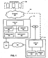
- Figure 1 shows one embodiment of a system 100 used for generating one or more open area maps.
- the system 100 includes, but is not limited to, an image source or sources 104, a network 108, advice 112, a network or connection 120, a database 170, a network 180, and a user device 116. Additional, fewer, or different components may be provides. For example, a proxy server, a name server, a map server, a cache server or cache network, a router, a switch or intelligent switch, a geographic database, additional computers or workstations, administrative components, such as an administrative workstation, a gateway device, a backbone, ports, network connections, and network interfaces may be piovided. While the components in Figure 1 are shown as separate from one another, one or more of these components may be combined.
- the image source 104 is a website, an application, a program, a workstation or computer, a file, a memory, a server, a beacon or map beacon, a depository, and/or any other hardware and/or software component or database that can store or include images or data associated with images.
- the image source 104 is one or more images.
- the image source 104 includes one or more images of a layout.
- the images are raster or pixel based images, such as a JPEG, Bitmap, Pixmap, Tiff, or other pixel or raster based file format.
- the images may be raster or pixilated scanned copies of paper or hard layouts (using received images in raster or pixel based format is outside the claim scope of the present invention.
- the images may be vector based images, vectorised images, or images in a vector graphics format layouts may correspond to real-world areas in which a person, pedestrian, or people walk and/or move about
- the layouts may also correspond to future real-world areas that have not been built yet
- the layouts may correspond to imaginary locales, settings, or areas (outside the claim scope of the present invention).
- the layouts may represent an unorganized or unconstrained geographic area.
- the layout is an area in which a pedestrian is not limited to travel only on a set road or path network. Rather, the pedestrian may walk through public plazas, parks, buildings, corridors, lobbies, or hallways having no associated road or path network or pattern. Additionally, the pedestrian does not have direction restrictions as a vehicle on a road. Moreover, the pedestrian has a greater degree of freedom of motion in the layout and may chose from a plethora of self-determined paths in any given open area.
- the images of the layouts may include images of a real-world building floor plan, a parking lot, a park, an indoor or outdoor recreation area, and/or other interior and exterior area plans corresponding to places where a person can walk or move ( e . g ., via a wheel chair, a bicycle, or other mobile assistance device).
- the images are pre-existing or publicly available images.
- the images are originally formed or created for purposes other than generating a routable map.
- the pre-existing images may be generated by an entity separate from a developer of a routable open area map and/or its end user.
- the pre-existing images are available to the public or an entity for free or for a purchase price ( e . g ., online).
- self-generated images, images originally generated for creating a routable map, or non-public images may be used.
- the image source 104 is in communication with the device 112 via the network 108.
- the network is the Internet, an intranet, a local area network ("LAN”), a wide area network (“WAN”), a virtual private network (“VPN”), a local wireless or wired connection ( e . g ., a USB connection or other device connection), and/or any known or future network or connection.
- LAN local area network
- WAN wide area network
- VPN virtual private network
- a local wireless or wired connection e . g ., a USB connection or other device connection
- the device 112 receives images of layouts from the image source 104 for generating routable open area maps.
- the device 112 is a workstation, computer, editing device, beacon or map beacon, and/or other computing or transmitting device.
- the device 112 is an editing workstation.
- the device 112 includes, but is not limited to, a display 124, a processor 128, a memory 132, an application 134, and an input device 136. Additional, fewer, or different components may be provided. Audio components may be provided. For example, a speaker, audio jacks, and/or other components for outputting or receiving audible or sound signals are provided.
- the display 124 is any mechanical and/or electronic display positioned for accessible viewing in, on, or in communication with the device 112.
- the display 124 is a touch screen, liquid crystal display ("LCD”), cathode ray tube (“CRT”) display, or a plasma display.
- the display 124 is operable to display images, such as images of layouts, floor plans, maps, or other areas.
- the input device 136 is a button, keypad, keyboard, mouse, trackball, rocker switch, touch pad, voice recognition circuit, or other device or component for controlling or inputting data in the device 112.
- the input device 136 may be used to perform functions, such as modifying received images (e.g ., adding doors or openings) or using eraser tools.
- the processor 128 is in communication with the memory 132, the application 134, the display 124, and the input device 136.
- the processor 128 may be in communication with more or fewer components.
- the processor 128 is a general processor, application-specific integrated circuit ("ASIC"), digital signal processor, field programmable gate array (“FPGA”), digital circuit, analog circuit, or combinations thereof.
- the processor 128 is one or more processors operable to control and/or communicate with the various electronics and logic of the device 112.
- the processor 128, the memory 132, and other circuitry may be part of an integrated circuit.
- the memory 132 is any known or future storage device.
- the memory 132 is a non-volatile and/or volatile memory, such as a Random Access Memory “RAM” (electronic), a Read-Only Memory “ROM” (electronic), or an Erasable Programmable Read-Only Memory (EPROM or Flash memory).
- RAM Random Access Memory
- ROM Read-Only Memory
- EPROM Erasable Programmable Read-Only Memory
- a memory network may be provided.
- the memory 132 may be part of the processor 128.
- the memory 132 is operable or configured to store images of layouts received by the image source 104.
- the memory 132 may also store images or data generated by the processor 128.
- the processor 128 is operable or configured to execute the application 134.
- the application 134 is a software program used to generate open area maps that are routable based on pre-existing images, such as the images received from the image source 104.
- the processor 128 runs the application 134 and creates or generates or assists in generation of a routable map via input from the input device 136 and/or automated commands.
- the application 134 may be stored in the memory 132 and/or other memory.
- the device 112 is operable or configured to send or transmit one or more generated routable open area maps to the user device 116, or the user device 116 may request a routable open area map via a network or connection 120.
- the connection 120 is the Internet, an intranet, a local area network ("LAN”), a wide area network (“WAN”), a virtual private network (“VPN”), a local wireless or wired connection (e . g., a USB connection or other device connection), and/or any known or future network or connection.
- the device 112 may store, upload, or send one or more generated routable open area maps or data thereof to the database 170.
- the database 170 may be a database, a memory, a website, a server, a beacon, or other device used for storing, receiving, and/or transmitting data corresponding to the routable open area maps.
- the database 170 may store data entities that represent different layers of the open area map, such as data corresponding to reference regions, cost, restrictions, a grid or array, image data, and/or other content.
- the user device 116 may obtain a routable open area map or data thereof from the database 170 via the network 180, such as without communicating with the device 112.
- the network 180 is the Internet, an intranet, a local area network ("LAN”), a wide area network (“WAN”), a virtual private network (“VPN”), a local wireless or wired connection (e . g ., a USB connection or other device connection), and/or any known or future network or connection.
- LAN local area network
- WAN wide area network
- VPN virtual private network
- a local wireless or wired connection e . g ., a USB connection or other device connection
- routable open area maps may be "pushed" onto the user device 116.
- beacons, map beacons, or other devices can transmit or send routable open area maps or related content to the user device 116 based on the location or position of the user device 116.
- a beacon can be placed at an entrance or passageway of a building or other area, and once the user device 116 comes within a certain range of the beacon, a routable open area map associated with the area and/or other related areas is sent to the user device 116.
- the user device 116 is used to operate one or more routable maps to allow a user to navigate in or on respective layouts or areas.
- the user device 116 is a cellular telephone, a mobile phone, a personal digital assistant ("PDA"), a watch, a personal navigation device ("PND”), a computer, a digital floor plan device, a portable or non-portable navigation device, a kiosk, and/or other fixed, removable, or transportable digital device.
- the user device 116 includes, but is not limited to, a display 140, a processor 144, and a memory 148. Additional, fewer, or different components may be provided. For example, audio and/or application components may be provided.
- the display 140, the processor 144, and the memory 148 may be similar to or different than the display 124, the processor 128, and the memory 132, respectively.
- a user such as a person working on a building floor, may want to be able to route or navigate about his or her building floor, Accordingly, an image of the layout of floor plan of the user's floor, which is stored in the image source 104, is transmitted and received at the device 112.
- Another entity such as a map developer, operates the device 112.
- the map developer may be a person, company, or entity that develops maps for navigation or obtains and maintains map data and/or a geographic database, such as NAVTEQ North America, LLC located in Chicago, Illinois.
- the map developer views the pre-existing image of the layout on the display 124 and generates a routable map based on the pre-existing image via the input device 136 and the software application 134.
- Automated commands and/or processes may be used in development of the routable open area map.
- the creation or generation of the routable open area map may be substantially entirely automated.
- the user may download or receive the routable map of his or her floor on the device 116.
- the user uses the user device 116 to download the mutable map from the device 112 or a storage site or component associated with the device 112 ( e.g ., via the connection 120, such as a USB connection, a wireless connection, or other connection).
- the user may download the routable map on a device (e.g., a computer or a jump/thumb drive) different than the user device 116 and then transfer the data associated with the routable map to the user device 116 or other user device. The user then uses the device 116 to display the routable map for routing, guidance, and/or navigation purposes regarding the building floor.
- a device e.g., a computer or a jump/thumb drive
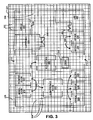
- FIG 2 is one embodiment of an image 201 of a layout used in the system 100.
- the image 201 may be a raster image (outside the claim scope of the present invention) or a vector graphics format image.
- Vector graphics formats include, but are not limited to, portable document format ("PDF"), scalable vector graphics ("SVG”), and post script ("PS").
- PDF portable document format
- SVG scalable vector graphics
- PS post script
- the image 201 is a pre-existing or publicly available image (e.g., is associated with the image source 104 or other source) that can be downloaded from the Internet or other network.
- the image 201 may be downloaded, received, obtained from a website or other source.
- the image 201 represents a real-world layout or floor plan of a building floor, such as a first floor or other floor.
- the image 201 includes graphical representations or icons of areas, spaces, and/or designations in the layout.
- the image 201 includes image reference objects, such as a men's room 217, a women's room 221, a cafeteria 225, offices 229, a conference room 233, a lab 237, a desk 241, and elevators or elevator bank 245.
- Image representations of doors 249 are also provided.
- the doors 249 are shown as a gap or opening in respective image reference objects.
- a door may be represented using a door symbol or image object 253 rather than an opening.
- the image 201 also includes an image representation of an open space, a walking grounds, a common or public area, and/or a hall area 209 for people to walk or move about to get from one place to another on the floor.
- Walls or barriers are depicted by corresponding, associated, or contiguous pixels or lines ( e . g ., a heavy line) of substantially the same or similar color.
- Entrances and/or exits 213 are depicted as openings or gaps in the walls or barriers that allow access between the interior area 209 and an exterior area 205.
- the exterior area 205 may represent an outer hallway, an outside of the building ( e . g ., a sidewalk, street, or road), or other exterior environment.
- Figure 3 is one embodiment of the image 201 corresponding to or undergoing a process used in the system 100 of Figure 1 .
- the image 201 is downloaded or received at the device 112.
- the image 201 is used to create or generate an open area map that is routable.
- a grid, mesh, or array 300 is applied on or over the image 201 or a copy of the image 201.
- the grid, mesh, or array 300 may be a grid or array of geometric shapes ( e . g ., uniform sized geometric shapes), such as tiles, sections, blocks, points, dots, circles, polygons, or other shapes.
- the grid or mesh 300 covers an entire ground area of the image 201.
- a ground area refers to a surface, plane, or floor or a portion thereof that can be walked upon as well as the surface in which objects or barriers may be placed or positioned on or over.
- the grid or mesh 300 includes areas, sections, blocks, or tiles 304.
- the grid, mesh, or array 300 may include unconnected dots or points corresponding to areas or sections similar to the tiles 304 ( e . g ., the dots or points replace or act as a substitute for the tiles 304).
- the tiles 304 have a substantially rectangular or square shape and are substantially uniform in size.
- the tiles 304 may have a circular, triangular, or other geometric or polygon shape, and the tiles 304 may be different sizes at different locations rather than being uniform.
- the grid 300 may be applied over certain areas of the layout rather than the entire image or entire ground area.
- the grid 300 may be applied only in hallway areas, such as the interior area 209.
- the grid 300 has a shape that corresponds to a pedestrian-accessible contiguous sub-area within the real-world area in which the shape has a boundary that corresponds to the walls in the pre-existing image.
- the grid 300 or portions thereof may also be applied to areas designated within an image reference object ( e . g ., the inner area of a room).
- tiles may automatically fill into contiguous open areas.
- a hallway or corridor area may be selected to automatically fill the area with tiles or sections of a grid or mesh.
- the tiles 304 may be assigned or designated coordinates, such as local or global map coordinates. For example, each center of a tile 304 or other part of the tile is given a (x,y), latitude and longitude, or other coordinate designation. One of the tiles 304, such as at a corner of the image, may be designated as an origin point (0,0) for reference and positioning purposes.
- the coordinates allows items, features, or regions to be searchable. However, for routing purposes, the coordinates may not be used.
- Figure 4 is one embodiment of the image 201 corresponding to or undergoing another step or process after the mesh 300 has been overlaid.
- Tiles that are not to be walked on or that are non-navigable are provided as tiles or area 401 ( e . g ., the tiles or area 401 may be replaced with unconnected dots or points that represent non-navigable areas).
- tiles surrounding or under or associated with borders or walls of the image reference objects e . g ., reference objects 217, 221, 225, 229, 233, 237, 241, and 245) are selected to be or are designated as non-navigable tiles 401.
- the image representation of the border, barrier or wall between the interior hall area 209 and the exterior area 205 is associated with the non-navigable tiles 401 for routing purposes.
- the tiles 401 allow routes to be prohibited from passing through walls or barriers to represent a real-world experience.
- doors 249 and 253 are associated with navigable tiles 304 to allow routing in and out of rooms or areas surrounded by tiles 401.
- tiles substantially adjacent or proximate to reference areas may be used for routing to and from respective reference areas.
- the non-navigable tiles 401 may be or represent tiles (or dots or points) removed from the grid 300 or may be tiles (or dots or points) designated with a non-navigable status.
- the non-navigable tiles 401 or the lack thereof may be represented as blank spaces, in which spaces that are free of the grid or tiles are not navigable for routing purposes.
- the non-navigable tiles 401 may be colored differently than the navigable tiles 304.
- Navigable or non-navigable tiles, dots, or points may be sub-classified.
- each or some tiles may be associated with a feature or location related to the layout.
- tiles may be linked or correspond to a washroom area, a narrow area, a windowed area, a dimly lit area, a high traffic area, a low traffic area, or other area or feature.
- classifying or sub-classifying the tiles one can input preferences for routing purposes. For example, a user may want to avoid high traffic areas, and, accordingly, the user may input his or her preference before or during routing.
- a wrap or boundary feature may be used regarding the grid 300.
- a person may want to route from one point in the interior area 209 to another point in the interior area 209, but a path is generated that routes the person out into the exterior area 205 and back into the area 209. Such routes may occur when it is optimum to route outside and back inside ( e . g ., when having multiple openings between interior and exterior areas).
- a wrap or boundary feature may be used that bounds all routing within the area 209 and associated areas. For example, a boundary line or designation may be allocated along the circumference of the inner area.
- the boundary feature will allow routing to the exterior area 205 when a user selects a destination point to be in the exterior area 205 or outside an inner area.
- the tiles of the exterior area 205 may be designated as non-navigable, or openings to the exterior area 205 may be associated with non-navigable tiles 401.
- connection point 405 is also provided.
- the connection point 405 may be generated or provided in a spatial or data layer separate from the grid or mesh 300.
- the connection point 405 is represented as a tile 304 or a subset of tiles 304 within an area.
- the connection point 405 may encompass the entire area of the elevators 245 or a portion thereof.
- the connection point 405 may not be associated with a reference image object or reference region.
- the connection point 405 represents or acts as a link to another map, such an open area map that is routable, for routing and navigation purposes.
- the connection point 405 may correspond to one or more elevators, a stairwell, an escalator, a ladder, or other feature for moving a person to another floor or area.
- connection points 405 may correspond to respective individual elevators or features.
- the connection point 405 is used to route between an area or point from the image 201 to another point or area on another map or floor plan, such as another map or floor plan representing another floor of the building ( e . g ., a second floor, a third floor, or Nth floor).
- the connection point 405 may represent a connection for moving or transferring a person from one point to another point on the same floor or ground area.
- the connection point 405 may correspond to a moving walkway or other transportation device.
- the connection point 405 may represent a connection to another routable open area map associated with the same level or area.
- a route may be generated to an area that is represented by a blank, unspecific, or general polygon or shape that represents a reference area, such as a food court.
- a connection point can be placed at, by, or on the general polygon that represents the reference area in which the connection point corresponds to or directs one to another routable open area map that has detailed features and/or reference regions within the original reference area ( e . g ., the food court).
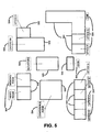
- Figure 5 is a diagram showing reference regions 500 corresponding to the image 201.
- the reference regions 500 are generated.
- the image reference objects 217, 221, 225, 229, 233, 237, 241, and 245 in the image 201 are part of a raster image or a pixilated image.
- the raster image may be binarized ( e . g ., converting pixels to black and white pixels and/or 1's and 0's).
- the device 112 extracts names or descriptions associated with the image reference objects. The separation allows for facilitation of optical character recognition ("OCR") to generate text 504 corresponding to the names or descriptions associated with the raster image 201.
- OCR optical character recognition
- the text 504 is used for searching or associating different areas of an open area map.
- the text 504 may match the names or descriptions of the image 201.
- additional or different text or information may be added. For example, text “A,” “B,” “C,” “D,” “E,” “F,” and “G” are added to the "office” text for differentiation purposes. The added text may or may not be visible to an end user.
- the image reference objects go through vectorization to form the polygons, reference regions, or areas 500.
- the reference regions 500 correspond to the different areas, rooms, or spaces in the image 201.
- the reference regions 500 are associated with or correspond to respective navigable tiles 304 and respective non-navigable tiles 401 represented by the grid 300 on a different spatial layer.
- reference regions or areas may be generated based on a vectorized or vector graphics format image.
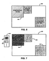
- Figure 6 is an example of a vector based image 520.
- the image 520 may be a PDF, PS, SVG, or other vector graphics format image. All or some features, components, or graphical representations in the image 520 are represented by vectors or line segments rather than pixels.
- references, image reference objects, or areas 524 ("conference room"), 528 ("office"), and 532 (“office”) may include or be represented by vector components as well as searchable text.
- raster/pixilated graphics or icons may be used in conjunction with vector based components to form an image.
- the conference room 524 may include a gradient filled color in which strength, type, or shading of the color changes along the area representing the conference room 524.
- the office 528 and the office 532 may have a flat color in which the color is constant or consistent about the area representing the offices 528 and 532.
- the offices 528 and/or 532 may include a complex, dynamic, patterned, or gradient color.
- Figure 7 shows an example of a raster or pixilated image 540 corresponding to the image 520.
- the image 520 may be converted into a SVG format.
- the SVG format is an open standard extensible markup language ("XML") format that gives access to graphics content, such as paths, text, fills, etc.
- XML extensible markup language
- color fill, text, and other components of the image may be represented by tags in the SVG or XML format.
- Text such as "conference room” or "office” may be removed or altered using the SVG or XML format (such as by deleting or altering text elements).
- a bounding box or text area is linked with or corresponds to a reference area, such as the areas 524, 528, and/or 532, to allow for association between text and respective regions ( e . g ., similar to the text 504 ( Figure 5 )).
- color may be removed or replaced.
- the gradient filled color of the conference room 524 may be replaced with a flat or constant color.
- the color of the offices 528 and 532 may or may not be replaced or changed based on whether or not the respective existing colors are a flat or consistent color.
- the raster image 540 is generated by rasterization or other pixel generating techniques.
- the image 540 includes image reference objects 544, 548, and 552 that correspond to the areas 524, 528, and 552, respectively.
- the image reference object has a flat or constant color that replaces the gradient fill of the area 524.
- the image reference objects 548 and 552 may have the same or different color or flat color of the respective offices 528 and 532.
- a toolbar, menu, or editor box 556 may be provided to assist a developer in generating reference regions.
- the menu 556 may include buttons or selection bars 560 and 564.
- the buttons 560 and 564 correspond to the different colors in the image 540, and the image reference objects having a certain color may be highlighted or color filtered by selecting the button with the respective color.
- Figure 8 is a highlighted or color-filtered image 570 corresponding to the raster image 540.
- the button 564 is selected to highlight the color corresponding to the image reference objects 548 and 552.
- color-filtering blacks out all color that does not correspond to the color selected, and/or the color that corresponds to the selected color is highlighted.
- the color-filtering allows the general shape of the respective reference objects 574 and 578 to be easily identified.
- the objects 574 and 578 correspond to the image reference objects 548 and 552, respectively, as well as the offices 528 and 532, respectively. Boundaries or vectors then outline the objects 574 and 578 to generate reference regions, such as the reference regions 500. Removed text may be bound to the generated reference regions based on computed bounding boxes.
- the grid or mesh layer may be compiled with the reference region layer, a connection layer, and/or other spatial or data layers, such as a cost layer or restriction layer, to form or generate an open area map that can be used for navigation and/or routing. Layers may also be combined at a runtime.
- Figure 9 shows one embodiment of an open area map 601 generated by the system 100 of Figure 1 .
- the open area map 601 may be displayed on the display 140 of the user device 116 or other display.
- the open area map 601 includes graphical representations of the reference image objects of the image 201.
- the image 201 is used as a background or base image for the open area map 601.
- different graphics or images are generated ( e . g ., based on the generation of the reference regions 500) to represent the original layout of the image 201.
- the grid 300 including the navigable tiles 304 and the non-navigable tiles 401 or lack thereof, compiled with the reference regions 500 and the connection point 405 underlie the open area map 601 for routing and navigation purposes.
- the grid 300 or compiled grid may not be seen by a user.
- the grid 300 and/or other features may be exposed to the user.
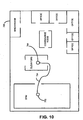
- Figure 10 shows one embodiment of an open area map 700 generated by the system 100 of Figure 1 .
- the open area map 700 represents another floor of the building that includes the floor represented by the open area map 601.
- the open area map 700 includes image reference objects, such as a breakroom, a conference room, elevators or elevator bank, offices, and a gym, as well as associated reference regions, a grid, a connection point 708, and navigable and non-navigable tiles similar to the respective features of the open area map 601 discussed above.
- a user may want to use the open area maps 601 and 700 to route from an office on one floor to the gym on another floor of the building.
- the user searches for the office, using a text search, to designate an origin point 609.
- the text for the particular office is associated with the respective reference region 500, which is associated with respective tiles 304 and 401.
- the user physically touches or selects the origin point 609 on the display.
- the origin point is determined based on a global positioning satellite ("GPS") system or device, an indoor location system (e . g ., WiFi based), or the fact that the location of the origin point is fixed ( e . g ., a kiosk or a floor plan device on a wall).
- GPS global positioning satellite
- the origin point 609 may correspond to one or more tiles within or associated with the reference region or reference image object of the office or may correspond to the entire area.
- the user searches for the gym, using a text search, to designate a destination point 712.
- the text for the gym is associated with the respective reference region for the gym, which is associated with respective tiles.
- the user physically touches or selects the destination point 712 on the display.
- the user may switch to the open area map 700 or may view both open area maps 601 and 700 on the same screen or window.
- a path 605 ( Figure 9 ) is generated based on the calculation.
- the path 605 is displayed for the user to view and follow.
- the path 605 shows a path that starts from the origin point 609 in the office, passes the conference room, and uses the elevators via a connection point 613, such as the connection 405.
- the open area map 700 shows a path 704 ( Figure 10 ) that starts from elevators at a connection point 708 and leads to the gym at the destination point 712.
- the calculation and determination of the routes and/or the paths 605 and 704 are based on or formed of adjacent, continuous, or connected tiles. For example, navigable tiles that border or touch each other are considered for point-to-point routing, in which any area in the layout or any point associated with adjacent tiles can be routed to based on calculation regarding the grid or mesh ( i . e ., not solely pre-determined routes). Adjacent tiles forming a route may be connected or linked by their center points or other parts.
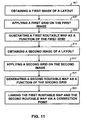
- Figure 11 is a flowchart of a method for generating an open area map, such as the open area map 601 or 700. Fewer or more steps or acts may be provided, and a combination of steps may be provided. Also, the steps or acts may be performed in the order as shown or in a different order. The method is implemented by the system and/or devices described herein or by different devices or systems.
- a graphical representation or an image of a layout is obtained or received (Step 801).
- a map developer using a workstation, computer, or other device such as the device 112 downloads or requests a pre-existing image of a layout, such as a building floor plan, via the Internet or other network or connection, such as the network 108.
- the graphical representation of the image may be stored or located at a website, server, file, another computer or other device, or any other storage device or area, such as the image source 104.
- the image of the layout may be received wirelessly and/or through a wired connection.
- the received image may be modified. For example, eraser or drawing tools or functions may be provided so that the map developer can add or remove image features. In some cases, doors or openings may need to be added for routing purposes.
- a grid, mesh, or array, such as the grid or array 300, is applied or overlaid on or over the image of the layout, a copy of the image of the layout, or a modified image of the layout (Step 805).
- the map developer assigns a scale by designating a distance measurement within the layout. For example, using a mouse or other input device, such as the input device 136, the map developer selects a space or distance between image objects, such as the image objects 217, 221, 225, 229, 233, 237, 241, and 245, representing a width or length of a hallway or area. The map developer then assigns a value to that space or distance, such as 1 meter or 3 meters.
- designating a distance measurement may be entered via a "pop-up" screen or a fill-in box, or the distance measurement may be automatically implemented based on pre-existing distance markers in the image or pre-determined parameters. By assigning a scale, an understanding of distances between objects and areas within the layout is achieved.
- the grid or mesh is then applied on the image of the layout, or the grid or mesh is applied before assigning the scale.
- a grid covering substantially the entire image of the layout is provided.
- certain or specific portions are chosen for applying the gird.
- the grid may be applied to only areas designated for walking between reference objects, such as hallways or other ground or open areas. Therefore, the grid or mesh does not intersect borders, barriers, and/or walls within the image.
- the grid or mesh may be applied on internal areas, such as areas within a room or image reference object. The map developer may choose where to apply the grid, portions of the grid, or multiple grids that may be joined via the input device.
- the map developer may click on or select a hallway area within the layout to apply a grid throughout the hallway area.
- a grid or a portion thereof is automatically overlaid over substantially the entire image of the layout or portions of the layout based on color/image recognition or other parameters.
- the grid, mesh, or array is composed of tiles, blocks, sections or areas, such as the tiles 304, or similar or corresponding dots or points, as mentioned above.
- the tiles are assigned or correspond to a measurement value.
- each tile may have a measurement value of about 1 square meter, 1/4 square meter, or other value.
- each tile may have any other measurement value or different values from each other.
- the resolution or number of tiles or points may be adjusted by the map developer or automatically. For example, for a finer resolution, the grid or mesh may be adjusted or changed to include more tiles or points, and for a lower resolution, the grid or mesh may be adjusted to include fewer tiles or points.
- the adjustment of the number of tiles or points may be based on the number or positioning of image reference objects within the layout and/or other factors.
- the size of the tiles may be selected to match a human or pedestrian scale so that at least one navigable tile may fit in narrow or narrowest passages in the real world environment.
- a maximum tile size e . g ., at most about 15, 20, or 30 inches in length and/or width or other length, width, dimensional, and/or area value
- An appropriate tile or area size is chosen to avoid the lack or inability of routing in some suitable areas of the layout.
- non-uniform sized tiles and/or shapes may be used for different areas. For example, larger areas may use larger sized tiles and smaller or narrow areas may use finer or smaller sized tiles.
- Local or global map coordinates are assigned or designated. For example, center of the tiles or other parts of the tiles (or points or dots of an array or grid) are given a (x,y), latitude and longitude, or other coordinate designation.
- An origin is selected by assigning a (0,0) or origin point to one of the tiles ( e . g ., a corner tile).
- the coordinates can be used for searching or identifying reference image objects, reference regions, or other features or vice versa .
- Point-to-point routing may, however, be based on adjacent or contiguous tiles, and, therefore, the coordinates may not be needed for routing calculations. Alternatively, the coordinates may be used for distance and cost determinations when calculating a route.
- a routable map such as the map 601 or 700, is generated or created based on or as a function of the grid, array, or mesh (Step 809).
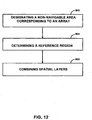
- Figure 12 is a flowchart showing an example of a method for generating the routable map including steps that may be wholly or partially encompassed by Step 809.
- a non-navigable area is designated in the grid or mesh (Step 900).
- the map developer clicks on or selects areas within the layout of the image to convert them to non-navigable tiles or areas, such as the non-navigable tiles or areas 401.
- the map developer may select images of walls or barriers that cannot be walked through in the real world as non-navigable areas.
- the selection may assign tiles with a non-navigable status or may remove tiles.
- the designation of non-navigable areas may also be automated. For example, instead of selecting multiple areas in the image to be non-navigable, the map developer may click on or select a wall or barrier to be non-navigable and all other features or image objects with the same or similar color or pixel level of the selected wall or barrier may automatically be associated with non-navigable areas or tiles. Alternatively, pre-determined color or pixel levels or image recognition factors may be entered so that non-navigable tiles or areas are automatically generated once a grid is overlaid without involvement of a map developer or other entity.
- graphical representations of text or descriptions of image objects in the layout may be removed or separated prior to designation of non-navigable areas. This is so because the descriptions may be mistakenly assigned as non-navigable areas.
- a non-navigable area may be designated by originally not applying a grid or a portion thereof to areas intended to be non-navigable.
- a plurality of reference regions or areas are generated (Step 904).
- the generation of the reference regions occurs on a different spatial layer than the grid or mesh.
- the grid or mesh may or may not be viewed when creating the plurality of reference regions.
- the plurality of reference regions are automatically or semiautomatically generated based on a raster image.
- a plurality of reference image objects are identified or determined in the raster image, such as the image 201.
- the raster image of the layout is binarized. Binarization of the image allows for logically comprehending the layout by using digital 1's and 0's.
- a Trier-Taxt binarization is used.
- the Trier-Taxt binarization provides for edge preservation.
- other binarization techniques or methods may be used.
- the binarization may depend on three parameters or factors, such as a sigma, an activity threshold, and a pruning factor. Alternatively, more or less factors may be considered.
- the sigma is a larger sigma rather than a lower sigma that may correspond to noise sensitivity.
- Activity at a pixel may be proportional to a local average of a gradient magnitude, and pixels with lower activity than the activity threshold may be set to zero.
- the pruning factor is used for removing small connected components. In one embodiment, the sigma is set to about 1, the activity threshold is set to about 2, and the pruning factor is set to about 1. Alternatively, the factor values may be set to any other value and may be adjustable.
- a text/graphics separation is performed after binarization.
- the graphical description or text corresponding to each of the reference image objects is separated from the respective image objects. Any future or past graphics-text separation may be used.
- the separated text is linked to or identified with the respective image object.
- a text region may be designated in each of the reference image objects.
- OCR is performed on all or some of the graphical descriptions to convert them into searchable text, such as the text 504, or text that can be recognized as having meaning or a definition rather than a graphical representation of text. Separation of the graphical descriptions may facilitate or improve the OCR.
- the OCR may be performed without the separation. Text aliasing may be reduced by doubling or increasing resolution of the original image of the layout, such as by using Lanczos re-sampling before applying OCR.
- other text recognition methods, functions, or algorithms may be used.
- the plurality of reference regions are generated by forming borders or boundaries corresponding to the respective reference image objects.
- the reference image objects are vectorized. Lines or vectors are generated or created between the digital or binarized data points to form shapes corresponding to the image objects within the layout.
- the Rosin and West vectorization algorithm is used. Alternatively, other future or past vectorization algorithms may be utilized.
- Closed polygons are identified to determine the reference regions associated with the original reference image objects. For example, based on the vectorization, closed polygons or other shapes are determined. The closed polygons may be determined via planar curve, vertices, edge, and/or face techniques. Any future or past computational-geometry algorithms or methods may be used. A closed polygon may correspond to an office, a room, or other area.
- Some reference image objects may include gaps or symbols of doors, such as the gaps or symbols 249 and 253.
- all line segments identified in the vectorization may be visited to determine or identify gaps that can be closed to form a closed polygon.
- the gaps are closed to identify the respective reference regions.
- the map developer may identify or provide information that links a unique symbol, such as the symbol 253, to a door, opening, entrance, and/or exit.
- the association may be stored in a memory or look-up-table.
- the symbols of the doors can be identified based on matching and replaced with gaps. The gaps are then closed to identify the respective reference regions.
- a line or vector replaces the symbol of the door to close the polygon rather than forming a gap and then closing the gap.
- Multiple gaps or symbols of doors for a given image object may be visited or closed to form a closed polygon for determining a reference region.
- the gaps or symbols of doors correspond to navigable tiles on the grid that is in a separate spatial layer relative to the reference image objects.
- the doors or openings may be inferred by comparing the navigable tiles of the grid with respective reference regions.
- reference regions are generated based on a received vector graphics format or vectorized image, such as the image 201 or 520.
- Figure 13 is a flowchart showing an example of a method for determining one or a plurality of reference regions including steps that may be wholly or partially encompassed by Step 904.
- the vectorized or vector based image is modified or altered (Step 1001).
- the vector based image may be converted to a SVG format.
- the vector based image may already be in a SVG format.
- the SVG format corresponds to an XML in which graphics content may be manipulated, changed, or removed using XML tags, queries, and/or other features.
- Text corresponding to or associated with the vector based image may be removed (Step 1005). Text within references or areas, such as the areas 524, 528, or 532, in the vector based image may bo removed from the SVG format.
- XPath queries e.g., "//text”
- the text and/or corresponding tag may be deleted or removed in the SVG format.
- a bounding box or text area may be saved or stored (such as in a look-up table or other memory) to associate the removed text with the respective region of the image.
- Color corresponding to or associated with the vector based image may be replaced or changed (Step 1007).
- the original vector based image may include complex color shading, such as gradient fills, that may it difficult to generate respective reference regions.
- XPath queries e.g ., "// @ fill”
- a tag in the SVG format may be changed to include instructions or data representing a flat color.
- color may be provided to areas that did not have color to aid in generating reference regions.
- the modified or altered vector based image is rasterized or pixilated (Step 1011). For example, after the SVG format is changed, pixels are created or burned to generate a raster base image, such as the image 540. Any known or future rasterization techniques or processes may be used.
- the raster image includes reference image objects, such as the objects 544, 548, and 552, with removed text as well as flat or consistent color.
- Boundaries of one or more objects are generated to form respective reference regions (Step 1021). For example, specific or certain objects in the raster image are highlighted or color-filtered.
- a menu or toolbar such as the toolbar 556, is provided to select from any of the colors in the raster image.
- a desired color is highlighted or identified. For example, a color of a certain type of reference object, such as the objects 548 and 552, is selected. Based on the selection, all other colours are blacked out, hidden, removed, or filtered to show the outlines of the selected objects, such as shown in the image 570.
- the respective objects that have been selected based on color may be highlighted with or without filtering the other colors (the latter being outside the claim scope of the present invention).
- the objects such as the objects 574 and 578
- boundaries, borders, or lines are formed or outlined around the perimeter of the objects to generate respective reference regions, such as the reference regions 500.
- a vectorization process may be used to connect lines to form a polygon that represents a reference region.
- the removed text may be bound or replaced In the generated reference regions. For example, based on the bounding boxes, the text that was removed is associated with regions of the image.
- the text may be aligned with the generated reference regions for appropriate association. Alignment or association of text may include using geometric techniques, such as looking at a maximum or greatest area in which the text overlaps, to determine the appropriate or correct generated reference region for the text.
- the original vectors or polygons in the received vector based image may be determined and used.
- the original vector graphics image such as the image 520, may be used to determine or identify polygons or vector objects.
- the lines or vectors associated with the office 532 are identified and used as a reference region, such as one of the reference regions 500.
- identifying determining, and/or using the original vector components may be difficult or may require more processing because the original vectorized image may include a complex data structure.
- PDFs or other vector graphics format images may include clipping masks, layered vector, data, and other components or features that may make it difficult to identify or determine reference regions or polygons in a form desired for use in the routable open area map.
- the names or text associated with each of the reference image objects are populated in a name attribute corresponding to the generated reference regions.
- the text generated from the OCR or vector based process is associated with text regions of the generated reference regions.
- a look-up-table, database, or other memory feature links the text descriptions to each respective reference region.
- a question and answer feature or a verification function may be implemented so that the map developer can correct errors in the generated text or association of text with reference regions.
- a reference region may be searchable based on the associated text and vice versa.
- the reference regions may also be associated with a reference type.
- each reference region may correspond to or be designated a type, such as a restaurant, office, department store, grocery store, bathroom, or other designation, based on the associated text, function, purpose, and/or other factors of the reference region.
- These types or keywords may be stored in a database or look-up-table and may be linked or associated with respective reference regions.
- the type or tag may be more specific, such as particular names of stores or areas ( e . g ., McDonalds TM restaurants) that may or may not be different than the generated text or name.
- logos and/or respective websites may be associated with the reference regions.
- a reference region may be associated with one or more types or tags and may be searchable based on the types or tags.
- the reference regions and associated text and type may be generated manually instead of or in addition to being automatically generated.
- the map developer using program or application tools, may outline or replicate the reference image objects in the original image of the layout to generate the reference regions, such as the reference regions 500, in a spatial layer separate from the grid or mesh.
- the map developer may read or view the original descriptions of the reference image objects and enter, input, or type in equivalent text, such as the text 504, and/or types to be associated with the generated reference regions.
- the generated data or data layers associated with a digital open area map, such as the grid or array and the reference regions are stored, such as in the database 170.
- Separate data or spatial layers may be stored as individual XML files or other data.
- data corresponding to the underlying image, the grid, cost, restrictions, and/or the reference regions are saved or stored.
- Position or location information or data corresponding to the grid or respective tiles (such as regular-sized tiles) as well as the reference regions or other data are also saved and/or provided in the data structure.
- the position information is used as a spatial reference regarding appropriate location of the different data entities.
- the position information may be based on an original scale, a reference, or coordinates, such as relative to the underlying image.
- the database 170 may compile the separate data layers to form a routable open area map. Accordingly, the database 170 may stream or send the compiled open area map data to the end user device. Alternatively, separate data layers may be sent to the end user device for compilation on the end user device. Also, a compiled open area map file or data may be stored in the database 170 rather than storing separate data layers.
- different spatial or data layers are compiled or combined to form an open area map, such as the open area map 601 or 700, that is routable (Step 908).
- the plurality of reference regions including the associated text and tags are compiled with the grid or mesh.
- the compilation links or associates respective tiles to the generated reference regions (such as tiles that are to be within a reference region, substantially adjacent to the reference region, and/or touching or intersecting a border of the reference region) for search, navigation, routing, and other purposes.
- connections or connections points which may be generated on a separate spatial layer, may be compiled with the grid and the plurality of reference regions.
- Other components or features, such as restrictions or cost features, that may be on separate or different spatial layers may also be compiled with the grid or mesh. Any future or past compilation technique or method may be used. Also, data layers may be combined at a runtime. Alternatively, the grid, reference regions, and/or connection points, as well as other features, may be generated and exist on the same spatial or data layer rather than different layers. Accordingly, a final compilation may not be required. Also, some spatial layers may not be compiled or may not be used. For example, routing may be accomplished using navigable and non-navigable tiles without associating the tiles with generated reference regions.
- the second image may be an image of a floor plan of another floor of the building ( e . g ., the image obtained at Step 801 represents one floor of a building and the image obtained at Step 813 represents another floor of the building).
- the second image may be obtained or received by the map developer in a similar manner as the first image was obtained at Step 801.
- Another grid, mesh, or array is applied to the second image (Step 817), such as applying the grid at Step 805.
- Another or second routable map is generated based on or as a function of the second grid (Step 821), such as generating the first routable map at Step 809.
- the first and second routable maps are linked or associated with each other, such as via one or more connections or other features (Step 825).
- a connection point in the first routable map is associated with a connection point on the second routable map for routing purposes.
- the connection points may correspond to an elevator connection, such as the connection points 613 and 708, or other connection linking two floors of a building or other areas.
- one or the same connection point is used to link the two routable maps.
- Any number of routable maps may be linked together via one or more connection points or other features ( e . g ., 1 to an Nth number of routable maps corresponding to different floors of a building or other areas may be generated and linked or associated together
- an end user uses a device, such as the device 116, for point-to-point routing or navigation in an open area.
- a device such as the device 116
- one or more routable open area maps such as the open area map 601 or 700, are downloaded or sent to the user device, such as via the connection 120 or other connection.
- one or more routable open area maps are "pushed" onto the user device via a proximity beacon or transmitter or other device based on location or position.
- the user views one or more open area maps, such as via the display 140.
- An origin or origin point such as the origin point 609, is selected.
- the user types in or enters an area or point of origin that acts as a starting location for routing.
- the user may enter a name or text describing a reference region, and the respective area in the open area map may be allocated as the origin point based on searching or accessing a look-up-table linking reference regions with names or text.
- the user may click on, select, or physically touch an area on the open area map ( i . e ., touch the display screen) to choose the origin point.
- the origin selected in the open area map is identified. For example, one or more tiles associated with the origin point or reference region associated with the origin point is determined, considered, recognized, targeted, focused upon, and/or highlighted for route calculation.
- a destination or destination point (i . e ., the place or area the user wants to be routed to), such as the destination point 712, is selected by the user in a similar manner to selecting the origin point or through different methods.
- the destination selected in the open area map is identified in a similar manner to identifying the origin point or through different methods.
- a route from the selected origin to the selected destination in the open area map is calculated. For example, adjacent or connected tiles that are navigable, such as the tiles 304, are assessed to determine an optimum or preferred route from the origin point to the destination point. Non-navigable areas or tiles, such as the tiles 401, are avoided or routed around.
- One or more possible routes may be calculated using geometric and/or mathematical functions or algorithms. For example, centers or other locations of each of the tiles are connected or associated with each other to form potential routes.
- An optimum route is chosen based on distance as well as other factors, such as cost, restrictions, or user preferences that may be inputted ( e . g , a user may want a route to avoid or pass by a desired area).
- the user preferences may be based on classification or sub-classification of tiles.
- each or some tiles are associated with a feature related to position, location, and/or type of area (e . g ., major, intermediate, or minor corridor, hallway, pathway, or area, high or low traffic area, unpopular or popular area, scenic area, narrow area, isolated area, sloped area, flat area, carpeted area, or size, length, or width of an area).
- the tiles may also be sub-classified based on what reference regions or areas they are linked to, proximate to, or pass by. Different tiles may be ranked or ordered based on the sub-classification.
- the user may input or choose to avoid high traffic areas or major corridors when routing.
- a Dijkstra method, an A-star algorithm or search, and/or other route exploration or calculation algorithms may be used to form lines, curves, or routes between the points of the connected tiles.
- a Douglas-Peucker method or algorithm may be used to smooth or simplify the calculated lines or routes. For example, by connecting the center of adjacent tiles together, jagged, sharp, or triangular edges may be formed in the route from the origin point to the destination point. To minimize distance and provide a smooth line or curve for the route, the Douglas-Peucker algorithm can find or provide an averaged route from the origin to the destination.
- the Douglas-Peucker algorithm is modified to avoid non-navigable tiles and may be adjusted to change threshold levels for line smoothing or averaging. Alternatively, other line smoothing algorithms or methods may be used.
- Calculated routes and generated paths may be saved or stored for future use. For example, once a path is generated, it may be saved as a pre-determined path that can be reused when a user desires to be routed from the same origin to the same destination. Some, rather than all, paths or routes may be saved. For example, routes or paths between major or popular reference regions may be stored while paths regarding less traveled or minor reference regions may not be stored. Also, partial routes or paths may be stored in which some parts of the path, not the entire path, are saved. Additionally, routes or paths between connections or connection points may be pre-calculated or predetermined and stored for routing. For example, a user may want to route from one point to another in which one or more connections may be used.
- a route is calculated from an origin to a connection as well as from the other connection to the destination, and the route between the connections has already been calculated, which saves time and processing.
- Routes may be stored, saved, ranked, or ordered in multiple data layers. For example, higher layers may include main, major, or more important routes. Alternatively, routes and paths are always recalculated and regenerated.
- a path from the selected origin to the selected destination is generated based on the calculation of the route.
- all of the tiles associated with an optimum or preferred route are identified or determined as the path.
- the Douglas-Peucker algorithm or other algorithm may form a line and/or curve that passes over certain navigable tiles. Those tiles are then identified, entered, stored, or highlighted as the path for the user to take to go from the origin point to the destination point.
- the determined path then is displayed, such as the displayed path 605 or 704, to the user in the open area map for routing purposes.
- the user may receive partitioned data when using the open area maps for routing and/or navigation.
- User devices such as the device 116, may include resource constrained components in which processing speeds, memory, or other features may not be as high, fast, or large as other devices. Accordingly, instead of downloading or executing all the data associated with multiple open area maps at the same time, data may be received or executed on an as needed basis. For example, a user may download or initiate one open area map or a portion thereof when beginning navigation ( e . g ., a first floor or a part of the first floor including the origin is displayed or loaded for routing). Then when the user enters or is routed to a connection or connection point ( e . g ., to go to a second or other floor or area), the connected open area map data is then downloaded or initiated for continuing the routing process. Also, different spatial layers or features of an open area map may be downloaded or executed on a partitioned basis or at different times.
- the open area maps discussed above may or may not include navigation related attributes or nodes and road or path segments that are collected and organized into a geographic database, such as used for in-vehicle navigation systems, portable navigation devices, real-world vehicle navigation maps, and/or real-world pedestrian navigation maps.
- the navigation attributes may include turn restriction content, speed limit information, optimal or popular path data, footpath content, sign information, and/or other attributes for performing navigation related functions, such as route calculation, destination time calculation, route guidance, and/or other real-world navigation functions.
- the open area maps may be connected or in communication with real-world vehicle and/or pedestrian maps or map data that are based on or include collected and organized navigation attributes and/or nodes and links or road/path segments.
- an open area map of a floor of a building, a building, or other open area map may connect to a road network map for routing and navigation purposes.
- a user may use a device to route within a building floor to navigate him or her to an outside area, such as the area 205 ( Figure 2 ). Once the user reaches the outside area, the user may want to use a set road network to navigate to another part of a city or other location.
- the user's device or other device that can communicate with the user's device may execute, bring up, or show a vehicle navigation map that performs navigation related functions regarding the road network. Any combination of open area maps and navigation maps or data based on collected attributes may be connected with each other for routing and/or navigation purposes.
- the open area maps used for routing focus on building floors or floor plans.
- the features described may be used for any number of open areas.
- images of layouts of parks and outdoor environments may be obtained and used to generate routable maps, as described above.
- Different sections of a park such as picnic areas, jungle gyms, slides, restrooms, and other areas, may be defined as separate reference regions. Therefore, routing can be generated over grassy areas similar to routing between offices mentioned above.
- Parks may have walking paths that may be incorporated in routing. Alternatively, predetermined walking paths or routes may be avoided in routing.
- non-navigable tiles may be used or implemented for borders or barriers.
- lakes, ponds, or other water areas in the park may be bordered with non-navigable tiles so that one is not routed through water.
- Other barriers or desired boundaries, such as hazardous areas, train tracks, or rocks, may be associated with non-navigable tiles.
- navigable tiles may be used if there is a reason to pass through some of these boundaries. For example, if a boat exists to take a person from one side of a lake to another, then a boat area may be associated with navigable tiles.
- the tiles or objects associated with the image of a park or outside, area may be sub-classified. For example, some tiles may be associated with grass areas and some tiles may be associated with sidewalks. A user or other entity may input a preference, such as grass only, sidewalk only, or other designation, for routing purposes. Accordingly, routes may be generated by avoiding or using certain specified tile types ( e.g ., generating a route over only grass areas and avoiding sidewalks or vice versa ).
- a pre-existing image of a parking lot may be obtained and used to generate a routable open area map.
- Each of the individual parking spaces may correspond to different reference regions.
- the outlines of the parking spaces may be considered barriers that may or may not be associated with non-navigable tiles.
- the outlines of the parking spaces may be designated as non-navigable areas so that a route is not generated through parking spaces ( e.g ., for safety to pedestrians, cyclists, or others, and also for practicality because the spaces may be filled with cars).
- certain areas of the outlines of the parking spaces may be designated as navigable to simulate the concept that pedestrians may walk or navigate between parked cars.
- the parking lot may have multiple levels of parking floors, which may be associated with each other via a connection, such as the connection 405, 613, or 708, representing an elevator, stairs, or other connection.
- routable open area maps For example, pre-existing images of amusement parks, malls, museums, and other indoor or outdoor areas may by obtained and used for generating routable maps or plans.
- an image of a trade show area or floor plan or other temporary layout may be obtained.
- the layout setup for a trade show may last or exist for only about a week, less than about 3 months, or other time periods.
- the image of the temporary layout may be obtained and used to generate a routable open area map as described above. Therefore, after a certain time period (such as less than about 3 months or other temporary time period), the generated routable map may no longer be applicable for the location or area.
- the generated open area map may be time boxed based on the time period of the temporary layout.
- the open area map or portions thereof, such as reference regions or other features may disappear, be erased, or be inoperable when the actual layout is changed or taken down after the allocated time period.
- the open area map or features thereof may be erased by the executing device based on a timer within the device or a communication or signal from an outside source.
- events or features associated with certain reference regions may be time boxed or used to time box the specific reference regions. For example, a speech, show, or activity may occur at a specific area ( e . g ., reference region) for a certain time period.
- reference region may be only routable or may only exist for the specific time period associated with the speech, show, or activity.
- reference regions may be mobile, such as a mobile truck or moveable store, which makes the reference regions temporary for a specific location.
- reference regions may be routable for a temporary time period based on how long an item is on sale for a given reference region, store, or stall.
- the grid or mesh may be a three-dimensional grid or mesh including points or coordinates in an x, y, and z direction ( e . g ., the coordinates may include longitude, latitude, and altitude information or local coordinates).
- the image of the layout obtained may include three-dimensional features.
- a floor plan may have floor ramps, steps or stairs, a bi-level area, or other features that are displayed or designated in three-dimensional space.
- a hill or peaks and valleys in a park area may be displayed or provided in a three-dimensional space.
- a three-dimensional grid or mesh may be applied on or over the image to generate a routable open area map as described above.
- the addition of the z direction may require additional calculation for determining a route and/or path. For example, height may be a factor in determining an optimum or preferred route.
- triangular sections or tiles may be used for the three-dimensional grid or mesh. Alternatively, other geometrical shapes may be utilized.
- a three-dimensional grid or mesh may be used for routing a person from one point to another in addition to helping a person find an object. For example, images of layouts of a grocery store or retail store having vertical shelves of products and goods may be obtained. A three-dimensional grid may be applied in which the floor area is overlaid with two or three dimensional tiles, and the vertical shelving areas are overlaid with a grid or mesh as well. Different products or goods on the shelves may be designated as reference regions. Accordingly, an open area map may be generated that can route a shopper or user to one place in the store to another place where a product can be found on a proximate or nearby shelf. Then a route can be calculated on the grid over the shelf or vertical area pointing to the specific or selected product. The shopper or user may not walk on the shelf, but the route may be useful in showing the shopper or user where exactly the product is on the shelf. Or, a route can be calculated to end at a ground or floor tile that is nearest to the shelf.
- color may be used to designate navigable and non-navigable areas.
- the color white may be associated with navigable areas and the color black may be associated with non-navigable areas. Any number and types of colors may be used.
- routes may be calculated based on the placement of respective navigable and non-navigable colors. For example, paths or routes may be generated within navigable colored areas and around non-navigable colored areas based on distance algorithms. Also, different shades of color or gradation of color may be used as factors or cost for calculating or generating routes.
- a map developer obtains an image and uses a workstation, computer, and/or device, such as the device 112, to generate a routable open area map.
- the open area map is then received by an end user or at an end user device, such as the user device 116.
- an end user or other entity separate from a map developer may obtain an image of a layout and generate a routable open area map automatically and/or manually.
- an end user may obtain and/or purchase a software application for creating open area maps from a map developer or other entity.
- the device 112 ( Figure 1 ) may be operated by an end user, such as a personal computer.
- the user device 116 may be used to generate and use a routable open area map, bypassing the device 112.
- the device 112 and the device 116 may be combined into one device or system.
- the logic, software, or instructions for implementing the processes, methods and/or techniques discussed above are provided on computer-readable storage media or memories or other tangible media, such as a cache, buffer, RAM, removable media, hard drive, other computer readable storage media, or any other tangible media.
- the tangible media include various types of volatile and nonvolatile storage media.
- the functions, acts, steps, or tasks illustrated in the figures or described herein are executed in response to one or more sets of logic or instructions stored in or on computer readable storage media.
- the functions, acts or tasks are independent of the particular type of instructions set, storage media, processor or processing strategy and may be performed by software, hardware, integrated circuits, firmware, micro code and the like, operating alone or in combination.
- processing strategies may include multiprocessing, multitasking, parallel processing and the like.
- the instructions are stored on a removable media device for reading by local or remote systems.
- the logic or instructions are stored in a remote location for transfer through a computer network or over telephone lines.
- the logic or instructions are stored within a given computer, central processing unit (“CPU”), graphics processing unit (“GPU”) or system.
Landscapes
- Engineering & Computer Science (AREA)
- Radar, Positioning & Navigation (AREA)
- Remote Sensing (AREA)
- Physics & Mathematics (AREA)
- General Physics & Mathematics (AREA)
- Theoretical Computer Science (AREA)
- Automation & Control Theory (AREA)
- Business, Economics & Management (AREA)
- Mathematical Physics (AREA)
- Educational Administration (AREA)
- Educational Technology (AREA)
- Navigation (AREA)
- Processing Or Creating Images (AREA)
- User Interface Of Digital Computer (AREA)
- Traffic Control Systems (AREA)
- Instructional Devices (AREA)
Claims (15)
- Verfahren, wobei das Verfahren umfasst:Empfangen (801, 813) eines Bilds (520) eines Anordnungsplans, der einem Echt-Welt-Gebiet entspricht, in dem sich eine Person umher bewegt, wobei das Bild (520) in einem Vektorgrafikformat vorgesehen ist und ein Bild-Referenzobjekt (524, 528, 532) aufweist;Erzeugen (1011) eines gerasterten Bilds (540) unter Verwendung des Bilds (520) des Anordnungsplans;Farbfiltern des gerasterten Bilds (540) zum Hervorheben des Bild-Referenzobjekts (524, 528, 532);Abgrenzen (1021) des hervorgehobenen Bild-Referenzobjekts (524, 528, 532) zum Erzeugen einer Grenze um das Bild-Referenzobjekt (524, 528, 532) herum in dem gerasterten Bild (540) zum Ausbilden einer Referenzregion (500), die für das Bild-Referenzobjekt (524, 528, 532) charakteristisch ist; undVerknüpfen eines Gitters (300) mit der Referenzregion (500) zum Erzeugen (809, 821) eines offenen Gebietsplans (601), der so ausgelegt ist, dass er ein Führen zu oder von dem Bild-Referenzobjekt (524, 528, 532) unter Verwendung der Referenzregion (500) ermöglicht.
- Verfahren nach Anspruch 1, wobei das Gitter (300) eine Vielzahl von Kacheln (304) aufweist und wobei das Führen das Berechnen einer Route (605) über angrenzende Kacheln (304) umfasst.
- Verfahren nach Anspruch 1, wobei das Verfahren das Modifizieren des Bilds (520) des Anordnungsplans vor dem Erzeugen des gerasterten Bilds (540) umfasst durch:Konvertieren (1003) des Bilds (520) des Anordnungsplans in ein skalierbares Vektorgrafikformat;Entfernen (1005) von Text aus dem skalierbaren Vektorgrafikformat; undErsetzen (1007) von Farbe in dem skalierbaren Grafikformat.
- Verfahren nach Anspruch 3, wobei das Ersetzen der Farbe das Ersetzen einer geneigten Farbfüllung durch eine ebene Farbfüllung umfasst.
- Verfahren nach Anspruch 1, wobei das Gitter (300) eine Vielzahl von Kacheln (304) umfasst und wobei die Grenze nicht navigierbaren Kacheln (401) zugeordnet ist.
- Verfahren nach Anspruch 1, wobei das Bild (520) des Anordnungsplans ein Bild eines Anordnungsplans umfasst, das ausgewählt ist aus einer Gruppe bestehend aus: einem Gebäude-Lageplan, einem Park-Anordnungsplan und einem Parkplatz-Anordnungsplan.
- Verfahren nach Anspruch 1, wobei das Bild-Referenzobjekt (524, 528, 532) ein Gebiet des Anordnungsplans ist und wobei die Referenzregion (500) ein Polygon umfasst, das dem Gebiet des Anordnungsplans entspricht.
- Verfahren nach Anspruch 1, wobei das Gitter (300) eine Vielzahl von Kacheln (304) umfasst und wobei das Verfahren das Definieren (900) von navigierbaren und nicht navigierbaren Kacheln (401) innerhalb des Gitters (300) umfasst, um das Berechnen einer Route (605) über angrenzende navigierbare Kacheln (304) zu ermöglichen.
- Verfahren nach Anspruch 8, wobei das Verfahren das Einstellen der Größe der Kacheln (304) so umfasst, dass jede für Fußgänger zugängliche Region des Bilds (520) von mindestens einer navigierbaren Kachel (304) überlagert wird.
- Verfahren nach Anspruch 1, wobei das Verfahren das Überlagern des Gitters (300) nur auf für Fußgänger zugängliche Regionen des Bilds (520) umfasst.
- Verfahren nach Anspruch 1, wobei das Verfahren das Zuordnen von Text (504) oder anderen Informationen zu der Referenzregion (500) umfasst, um das Führen zu oder von dem Bild-Referenzobjekt (524, 528, 532) zu vereinfachen.
- Verfahren nach Anspruch 1, wobei das Verfahren das Definieren (825) eines Verbindungspunkts (613, 708) umfasst, der so ausgelegt ist, dass er eine erste Region (601) des Anordnungsplans mit einer zweiten Region (700) des Anordnungsplans verknüpft, um ein Führen zu oder von dem Bild-Referenzobjekt (524, 528, 532) über den Verbindungspunkt (613, 708) zu ermöglichen.
- Verfahren nach Anspruch 12, wobei die erste (601) und die zweite (700) Region voneinander entfernt sind.
- Einrichtung (112, 116), die einen Prozessor (128, 144) und einen Speicher (132, 148) mit einem Computerprogrammcode umfasst, wobei der Speicher (132, 148) und der Computerprogrammcode so ausgelegt sind, dass sie mit dem Prozessor (128, 144) die Einrichtung (112, 116) in die Lage versetzen, mindestens:ein Bild (520) eines Anordnungsplans, der einem Echt-Welt-Gebiet entspricht, in dem sich eine Person umher bewegt, zu empfangen (801, 813), wobei das Bild (520) in einem Vektorgrafikformat vorgesehen ist und ein Bild-Referenzobjekt (524, 528, 532) aufweist;ein gerastertes Bild (540) unter Verwendung des Bilds (520) des Anordnungsplans zu erzeugen (1011);Farbe aus dem gerasterte Bild (540) zu filtern, um das Bild-Referenzobjekt (524, 528, 532) hervorzuheben;das hervorgehobene Bild-Referenzobjekt (524, 528, 532) abzugrenzen (1021), um eine Grenze um das Bild-Referenzobjekt (524, 528, 532) in dem gerasterten Bild (540) herum zu erzeugen, um eine Referenzregion (500) auszubilden, die für das Bild-Referenzobjekt (524, 528, 532) charakteristisch ist, undein Gitter (300) mit den Referenzregionen (500) zu verknüpfen, um einen offenen Gebietsplan (601) zu erzeugen (809, 821), der so ausgelegt ist, dass er ein Führen zu oder von dem Bild-Referenzobjekt (524, 528, 532) unter Verwendung der Referenzregion (500) ermöglicht.
- Einrichtung oder computerlesbares Medium (132, 148), das computerausführbare Anweisungen aufweist, die zum Ausführen des Verfahrens nach einem der Ansprüche 1 bis 13 ausgelegt sind.
Applications Claiming Priority (1)
| Application Number | Priority Date | Filing Date | Title |
|---|---|---|---|
| US12/179,726 US8339417B2 (en) | 2008-07-25 | 2008-07-25 | Open area maps based on vector graphics format images |
Publications (3)
| Publication Number | Publication Date |
|---|---|
| EP2148170A2 EP2148170A2 (de) | 2010-01-27 |
| EP2148170A3 EP2148170A3 (de) | 2013-12-11 |
| EP2148170B1 true EP2148170B1 (de) | 2015-09-09 |
Family
ID=41226299
Family Applications (1)
| Application Number | Title | Priority Date | Filing Date |
|---|---|---|---|
| EP09251455.3A Active EP2148170B1 (de) | 2008-07-25 | 2009-06-01 | Offene Gebietspläne basierend auf Vektorgraphikformatbildern |
Country Status (3)
| Country | Link |
|---|---|
| US (1) | US8339417B2 (de) |
| EP (1) | EP2148170B1 (de) |
| JP (1) | JP5933908B2 (de) |
Families Citing this family (45)
| Publication number | Priority date | Publication date | Assignee | Title |
|---|---|---|---|---|
| US10657314B2 (en) * | 2007-09-11 | 2020-05-19 | E-Plan, Inc. | System and method for dynamic linking between graphic documents and comment data bases |
| US8825387B2 (en) * | 2008-07-25 | 2014-09-02 | Navteq B.V. | Positioning open area maps |
| US8229176B2 (en) | 2008-07-25 | 2012-07-24 | Navteq B.V. | End user image open area maps |
| US20100023251A1 (en) * | 2008-07-25 | 2010-01-28 | Gale William N | Cost based open area maps |
| US8417446B2 (en) * | 2008-07-25 | 2013-04-09 | Navteq B.V. | Link-node maps based on open area maps |
| US8339417B2 (en) | 2008-07-25 | 2012-12-25 | Navteq B.V. | Open area maps based on vector graphics format images |
| US8374780B2 (en) * | 2008-07-25 | 2013-02-12 | Navteq B.V. | Open area maps with restriction content |
| US20100021013A1 (en) * | 2008-07-25 | 2010-01-28 | Gale William N | Open area maps with guidance |
| US8099237B2 (en) | 2008-07-25 | 2012-01-17 | Navteq North America, Llc | Open area maps |
| US8284170B2 (en) | 2008-09-30 | 2012-10-09 | Apple Inc. | Touch screen device, method, and graphical user interface for moving on-screen objects without using a cursor |
| US8948913B2 (en) * | 2009-10-26 | 2015-02-03 | Electronics And Telecommunications Research Institute | Method and apparatus for navigating robot |
| JP4759081B2 (ja) * | 2009-11-11 | 2011-08-31 | 1stホールディングス株式会社 | チャート描画装置およびチャート描画方法 |
| US8660316B2 (en) | 2010-03-04 | 2014-02-25 | Navteq B.V. | Navigating on images |
| US8798840B2 (en) | 2011-09-30 | 2014-08-05 | Irobot Corporation | Adaptive mapping with spatial summaries of sensor data |
| WO2013104127A1 (en) * | 2012-01-12 | 2013-07-18 | Google Inc. | Generating an indoor map model |
| US9173069B2 (en) * | 2012-01-12 | 2015-10-27 | Google Inc. | Navigating using an indoor map representation |
| US9043722B1 (en) | 2012-06-19 | 2015-05-26 | Surfwax, Inc. | User interfaces for displaying relationships between cells in a grid |
| DE102012212740A1 (de) * | 2012-07-19 | 2014-05-22 | Continental Automotive Gmbh | System und Verfahren zum Aktualisieren einer digitalen Karte eines Fahrerassistenzsystems |
| US9135602B2 (en) | 2012-07-25 | 2015-09-15 | E-Plan, Inc. | Management of building plan documents utilizing comments and a correction list |
| US20140137017A1 (en) * | 2012-11-14 | 2014-05-15 | Qualcomm Incorporated | Region marking for an indoor map |
| US20140214473A1 (en) * | 2013-01-30 | 2014-07-31 | Carl Gentile | Method and system for providing enhanced sales and marketing tool |
| CN105824840B (zh) | 2015-01-07 | 2019-07-16 | 阿里巴巴集团控股有限公司 | 一种用于区域标签管理的方法及装置 |
| US20170031925A1 (en) * | 2015-07-27 | 2017-02-02 | Cisco Technology, Inc. | Mapping dynamic spaces and way finding related to the mapping |
| US10897490B2 (en) | 2015-08-17 | 2021-01-19 | E-Plan, Inc. | Systems and methods for augmenting electronic content |
| CN106482739B (zh) * | 2016-11-30 | 2020-07-17 | 英华达(上海)科技有限公司 | 自动导引运输车导航方法 |
| US11934374B2 (en) * | 2017-05-26 | 2024-03-19 | David Young | Network-based content submission and contest management |
| EP3607268B1 (de) | 2017-06-02 | 2022-11-09 | Apple Inc. | Örtlichkeitskartenanwendung und -system |
| US10410350B2 (en) | 2017-10-30 | 2019-09-10 | Rakuten, Inc. | Skip architecture neural network machine and method for improved semantic segmentation |
| US10395147B2 (en) * | 2017-10-30 | 2019-08-27 | Rakuten, Inc. | Method and apparatus for improved segmentation and recognition of images |
| CN111413960A (zh) * | 2018-12-19 | 2020-07-14 | 深圳市优必选科技有限公司 | 一种基于虚拟轨道的巡航方法、装置及终端设备 |
| US11922549B2 (en) | 2019-07-19 | 2024-03-05 | Semiconductor Energy Laboratory Co., Ltd. | Object-to-text conversion method and system |
| US11525243B2 (en) * | 2019-09-16 | 2022-12-13 | Caterpillar Inc. | Image-based productivity tracking system |
| CN112150390B (zh) * | 2020-09-30 | 2023-01-03 | 北京小狗吸尘器集团股份有限公司 | 图像去噪方法、装置、计算机可读存储介质及电子设备 |
| US12092464B2 (en) * | 2021-05-06 | 2024-09-17 | International Business Machines Corporation | Indoor navigational mapping through pixel color matching |
| US20220364878A1 (en) * | 2021-05-17 | 2022-11-17 | International Business Machines Corporation | Indoor navigational route enhancements using contextual data implied by map colors |
| US20230098595A1 (en) * | 2021-09-28 | 2023-03-30 | Unearthed Land Technologies, Llc | Generating vector versions of structural plans |
| US12002369B2 (en) | 2021-11-12 | 2024-06-04 | Rockwell Collins, Inc. | Graphical user interface (GUI) for selection and display of enroute charts in an avionics chart display system |
| US12306007B2 (en) | 2021-11-12 | 2025-05-20 | Rockwell Collins, Inc. | System and method for chart thumbnail image generation |
| US11887222B2 (en) | 2021-11-12 | 2024-01-30 | Rockwell Collins, Inc. | Conversion of filled areas to run length encoded vectors |
| US12254282B2 (en) | 2021-11-12 | 2025-03-18 | Rockwell Collins, Inc. | Method for automatically matching chart names |
| US11954770B2 (en) | 2021-11-12 | 2024-04-09 | Rockwell Collins, Inc. | System and method for recreating graphical image using character recognition to reduce storage space |
| US12304648B2 (en) | 2021-11-12 | 2025-05-20 | Rockwell Collins, Inc. | System and method for separating avionics charts into a plurality of display panels |
| US11748923B2 (en) | 2021-11-12 | 2023-09-05 | Rockwell Collins, Inc. | System and method for providing more readable font characters in size adjusting avionics charts |
| US11915389B2 (en) | 2021-11-12 | 2024-02-27 | Rockwell Collins, Inc. | System and method for recreating image with repeating patterns of graphical image file to reduce storage space |
| US11842429B2 (en) | 2021-11-12 | 2023-12-12 | Rockwell Collins, Inc. | System and method for machine code subroutine creation and execution with indeterminate addresses |
Family Cites Families (101)
| Publication number | Priority date | Publication date | Assignee | Title |
|---|---|---|---|---|
| US4674048A (en) * | 1983-10-26 | 1987-06-16 | Automax Kabushiki-Kaisha | Multiple robot control system using grid coordinate system for tracking and completing travel over a mapped region containing obstructions |
| US4674773A (en) * | 1984-01-23 | 1987-06-23 | Teleco Oilfield Services Inc. | Insulating coupling for drill collars and method of manufacture thereof |
| NL8500529A (nl) * | 1985-02-25 | 1986-09-16 | Ind Contractors Holland Bv | Stelsel voor het bepalen van de positie van een niet aan een vaste baan gebonden voertuig. |
| JPS63200207A (ja) * | 1987-02-14 | 1988-08-18 | Fujitsu Ltd | 移動経路探索方法 |
| NL8900056A (nl) * | 1989-01-11 | 1990-08-01 | Philips Nv | Werkwijze voor het visueel weergeven van een deel van een topografische kaart, alsmede inrichting geschikt voor een dergelijke werkwijze. |
| JPH0313611A (ja) * | 1989-06-07 | 1991-01-22 | Toshiba Corp | 自動清掃装置 |
| JP2792210B2 (ja) * | 1990-07-03 | 1998-09-03 | 富士電機株式会社 | 無人搬送車の制御方法および制御装置 |
| US5272638A (en) * | 1991-05-31 | 1993-12-21 | Texas Instruments Incorporated | Systems and methods for planning the scheduling travel routes |
| EP0546633A2 (de) * | 1991-12-11 | 1993-06-16 | Koninklijke Philips Electronics N.V. | Bahnführung in unbestimmter Umgebung |
| JPH05334430A (ja) | 1992-05-28 | 1993-12-17 | Toshiba Corp | 自動ベクトル化装置 |
| US5491641A (en) * | 1993-10-04 | 1996-02-13 | Lsi Logic Corporation | Towards optical steiner tree routing in the presence of rectilinear obstacles |
| US6321158B1 (en) * | 1994-06-24 | 2001-11-20 | Delorme Publishing Company | Integrated routing/mapping information |
| US5938720A (en) * | 1995-02-09 | 1999-08-17 | Visteon Technologies, Llc | Route generation in a vehicle navigation system |
| JP3369368B2 (ja) * | 1995-10-11 | 2003-01-20 | 富士通株式会社 | 画像処理装置 |
| US5842145A (en) * | 1996-07-08 | 1998-11-24 | Zimmer; John S. | Apparatus for providing individualized maps to pedestrians |
| NL1006710C2 (nl) * | 1997-08-04 | 1999-02-25 | Frog Navigation Systems B V | Systeem en werkwijze voor het besturen van voertuigen. |
| DE19803659A1 (de) * | 1998-01-30 | 1999-08-05 | Nokia Mobile Phones Ltd | Navigationsverfahren, insbesondere für Fahrzeuge |
| US6038559A (en) * | 1998-03-16 | 2000-03-14 | Navigation Technologies Corporation | Segment aggregation in a geographic database and methods for use thereof in a navigation application |
| WO1999060338A1 (en) * | 1998-05-15 | 1999-11-25 | Hitachi, Ltd. | Data processing apparatus and navigation system for pedestrians using the same |
| US6167332A (en) * | 1999-01-28 | 2000-12-26 | International Business Machines Corporation | Method and apparatus suitable for optimizing an operation of a self-guided vehicle |
| JP2000293099A (ja) * | 1999-04-09 | 2000-10-20 | Toyota Motor Corp | 地図データベース |
| US6850946B1 (en) * | 1999-05-26 | 2005-02-01 | Wireless Valley Communications, Inc. | Method and system for a building database manipulator |
| JP2001165671A (ja) * | 1999-12-14 | 2001-06-22 | Pioneer Electronic Corp | ナビゲーションシステム |
| JP2001209692A (ja) * | 2000-01-25 | 2001-08-03 | Shimizu Corp | 施設管理システム |
| US6604126B2 (en) * | 2001-04-11 | 2003-08-05 | Richard S. Neiman | Structural data presentation method |
| US20020168084A1 (en) * | 2001-05-14 | 2002-11-14 | Koninklijke Philips Electronics N.V. | Method and apparatus for assisting visitors in navigating retail and exhibition-like events using image-based crowd analysis |
| KR100420171B1 (ko) * | 2001-08-07 | 2004-03-02 | 삼성광주전자 주식회사 | 로봇 청소기와 그 시스템 및 제어방법 |
| JP3841401B2 (ja) * | 2001-09-26 | 2006-11-01 | 株式会社東芝 | 構内案内装置、サーバ装置およびプログラム |
| US20030210139A1 (en) * | 2001-12-03 | 2003-11-13 | Stephen Brooks | Method and system for improved security |
| IE20030139A1 (en) * | 2002-02-27 | 2003-10-01 | Ind Interfaces Ltd | A risk mapping system |
| JP3945279B2 (ja) * | 2002-03-15 | 2007-07-18 | ソニー株式会社 | 障害物認識装置、障害物認識方法、及び障害物認識プログラム並びに移動型ロボット装置 |
| GB2386971B (en) * | 2002-03-26 | 2005-11-30 | Mcmurtry Ltd | Method of operating an automated land maintenance vehicle |
| AU2003265400A1 (en) * | 2002-08-13 | 2004-02-25 | Drs Communications Company, Llc | Method and system for determining relative positions of networked mobile communication devices |
| US7188056B2 (en) * | 2002-09-09 | 2007-03-06 | Maia Institute | Method and apparatus of simulating movement of an autonomous entity through an environment |
| EP1554639B1 (de) * | 2002-10-23 | 2007-12-12 | Siemens Aktiengesellschaft | Verfahren und anordnung sowie computerprogramm mit programmcode-mitteln und computerprogramm-produkt zur bildung einer graphenstruktur zur beschreibung einer fläche mit einer freifläche und einer belegtfläche |
| US6782319B1 (en) * | 2002-11-26 | 2004-08-24 | Navteq North America, Llc | Method for organizing map data |
| US7233698B2 (en) * | 2002-12-13 | 2007-06-19 | The Boeing Company | Apparatus and methods for converting raster illustrated parts images into intelligent vector-layered files |
| US20040113937A1 (en) * | 2002-12-13 | 2004-06-17 | Sawdey David M | Method and apparatus for improved computer-aided facilities management |
| US7805220B2 (en) * | 2003-03-14 | 2010-09-28 | Sharper Image Acquisition Llc | Robot vacuum with internal mapping system |
| KR100471300B1 (ko) * | 2003-04-21 | 2005-03-10 | 현대자동차주식회사 | 네비게이션용 맵 데이터 전송 시스템 및 방법 |
| GB0314770D0 (en) * | 2003-06-25 | 2003-07-30 | Ibm | Navigation system |
| US7308118B1 (en) * | 2003-08-04 | 2007-12-11 | A. Jay Simecek | Building security, occupant safety, and emergency response |
| JP3994950B2 (ja) * | 2003-09-19 | 2007-10-24 | ソニー株式会社 | 環境認識装置及び方法、経路計画装置及び方法、並びにロボット装置 |
| US7719542B1 (en) * | 2003-10-10 | 2010-05-18 | Adobe Systems Incorporated | System, method and user interface controls for communicating status information |
| JP4695830B2 (ja) * | 2003-11-10 | 2011-06-08 | 日立オートモティブシステムズ株式会社 | 移動体用領域地図提供装置 |
| AU2004298635B2 (en) * | 2003-12-18 | 2008-02-28 | 1626628 Ontario Limited | System, apparatus and method for mapping |
| CA2553628A1 (en) * | 2004-01-15 | 2005-07-28 | Algotec Systems Ltd. | Targeted marching |
| US7272492B2 (en) * | 2004-03-16 | 2007-09-18 | The Johns Hopkins University | Path planning for mine countermeasures |
| JP2006010563A (ja) * | 2004-06-28 | 2006-01-12 | Jr Higashi Nippon Consultants Kk | 歩行者用ナビゲーションシステム |
| US7421341B1 (en) * | 2004-06-30 | 2008-09-02 | Navteq North America, Llc | Method of collecting information for a geographic database for use with a navigation system |
| US7660441B2 (en) * | 2004-07-09 | 2010-02-09 | Southern California, University | System and method for fusing geospatial data |
| US7672778B1 (en) * | 2004-07-20 | 2010-03-02 | Navteq North America, Llc | Navigation system with downloaded map data |
| US7439878B2 (en) * | 2004-09-10 | 2008-10-21 | Xanavi Informatics Corporation | Apparatus and method for processing and displaying traffic information in an automotive navigation system |
| US7376510B1 (en) | 2004-11-05 | 2008-05-20 | Navteq North America, Llc | Map display for a navigation system |
| KR100745975B1 (ko) * | 2004-12-30 | 2007-08-06 | 삼성전자주식회사 | 그리드 맵을 사용하여 최소 이동 경로로 이동하는 방법 및장치 |
| US7260474B1 (en) * | 2005-02-08 | 2007-08-21 | Cellco Partnership | GIS point-to-point routing for directions |
| JP2006239844A (ja) * | 2005-03-04 | 2006-09-14 | Sony Corp | 障害物回避装置、障害物回避方法及び障害物回避プログラム並びに移動型ロボット装置 |
| JP2006253888A (ja) * | 2005-03-09 | 2006-09-21 | Mitsubishi Electric Corp | 位置情報管理装置及び位置情報管理方法 |
| US7512485B2 (en) * | 2005-03-29 | 2009-03-31 | International Business Machines Corporation | Method for routing multiple paths through polygonal obstacles |
| US8836580B2 (en) * | 2005-05-09 | 2014-09-16 | Ehud Mendelson | RF proximity tags providing indoor and outdoor navigation and method of use |
| US7496445B2 (en) * | 2005-04-27 | 2009-02-24 | Proxemics, Llc | Wayfinding |
| DE102005035908A1 (de) * | 2005-07-28 | 2007-02-08 | X-Aitment Gmbh | Taktische Analyse von Closed Combat Situationen |
| ATE527518T1 (de) * | 2005-11-09 | 2011-10-15 | Harman Becker Automotive Sys | Bestimmung einer optimalen route mit karten- kacheln |
| US20070118821A1 (en) * | 2005-11-18 | 2007-05-24 | Sun Microsystems, Inc. | Displaying consumer device graphics using scalable vector graphics |
| JP5442259B2 (ja) * | 2005-12-07 | 2014-03-12 | カタリナ マーケティング コーポレーション | カラー印刷技術 |
| US7450003B2 (en) * | 2006-02-24 | 2008-11-11 | Yahoo! Inc. | User-defined private maps |
| US7587274B2 (en) * | 2006-03-14 | 2009-09-08 | Sap Ag | System and method for navigating a facility |
| US20070233367A1 (en) * | 2006-03-31 | 2007-10-04 | Geospot, Inc. | Methods for Interaction, Sharing, and Exploration over Geographical Locations |
| GB0608069D0 (en) * | 2006-04-24 | 2006-05-31 | Pandora Int Ltd | Image manipulation method and apparatus |
| US7598966B2 (en) * | 2006-05-03 | 2009-10-06 | Honeywell International Inc. | Methods and systems for automatically rendering information on a display of a building information system |
| US7543882B2 (en) * | 2006-05-05 | 2009-06-09 | Ford Global Technologies, Llc | Dual cell rear corner pillar for automobiles |
| US7873469B2 (en) * | 2006-06-19 | 2011-01-18 | Kiva Systems, Inc. | System and method for managing mobile drive units |
| JP4757120B2 (ja) * | 2006-07-06 | 2011-08-24 | キヤノン株式会社 | 画像処理装置及びその制御方法 |
| US7633383B2 (en) * | 2006-08-16 | 2009-12-15 | International Business Machines Corporation | Systems and arrangements for providing situational awareness to an operator of a vehicle |
| WO2008030889A2 (en) * | 2006-09-06 | 2008-03-13 | Johnson Controls Technology Company | Space management system and method |
| KR100803947B1 (ko) * | 2006-12-01 | 2008-02-15 | 주식회사 코아로직 | 오픈 벡터그래픽 응용 프로그램 인터페이스 변환 장치와방법, 모바일 단말기, 및 그 방법이 기록된 기록매체 |
| US7751971B2 (en) * | 2007-01-17 | 2010-07-06 | Microsoft Corporation | Location mapping for key-point based services |
| US20080183483A1 (en) * | 2007-01-17 | 2008-07-31 | Hart Marcia A | Office management solution |
| US8111257B2 (en) * | 2007-03-06 | 2012-02-07 | Aiseek Ltd. | System and method for the generation of navigation graphs in real-time |
| US8000892B2 (en) * | 2007-06-12 | 2011-08-16 | Campus Destinations, Inc. | Pedestrian mapping system |
| JP5047709B2 (ja) * | 2007-07-04 | 2012-10-10 | 株式会社日立製作所 | 移動装置、システム、移動方法及び移動プログラム |
| WO2009021068A1 (en) * | 2007-08-06 | 2009-02-12 | Trx Systems, Inc. | Locating, tracking, and/or monitoring personnel and/or assets both indoors and outdoors |
| US7920961B2 (en) * | 2007-08-29 | 2011-04-05 | Sap Ag | Method and apparatus for path planning and distance calculation |
| US20090088916A1 (en) * | 2007-09-28 | 2009-04-02 | Honeywell International Inc. | Method and system for automatic path planning and obstacle/collision avoidance of autonomous vehicles |
| US8531449B2 (en) * | 2007-12-18 | 2013-09-10 | Navteq B.V. | System and method for producing multi-angle views of an object-of-interest from images in an image dataset |
| US20100275018A1 (en) * | 2007-12-20 | 2010-10-28 | Pedersen Thomas Jam | System and method for conversion and distribution of graphical objects |
| US8209635B2 (en) * | 2007-12-20 | 2012-06-26 | Sony Mobile Communications Ab | System and method for dynamically changing a display |
| JP4513073B2 (ja) * | 2007-12-25 | 2010-07-28 | アイシン・エィ・ダブリュ株式会社 | ナビゲーション装置およびプログラム |
| US20090237396A1 (en) * | 2008-03-24 | 2009-09-24 | Harris Corporation, Corporation Of The State Of Delaware | System and method for correlating and synchronizing a three-dimensional site model and two-dimensional imagery |
| US8761810B2 (en) * | 2008-06-27 | 2014-06-24 | Verizon Patent And Licensing Inc. | Premises area map systems and methods |
| US8229176B2 (en) * | 2008-07-25 | 2012-07-24 | Navteq B.V. | End user image open area maps |
| US8374780B2 (en) * | 2008-07-25 | 2013-02-12 | Navteq B.V. | Open area maps with restriction content |
| US20100023251A1 (en) * | 2008-07-25 | 2010-01-28 | Gale William N | Cost based open area maps |
| US8339417B2 (en) | 2008-07-25 | 2012-12-25 | Navteq B.V. | Open area maps based on vector graphics format images |
| US8417446B2 (en) * | 2008-07-25 | 2013-04-09 | Navteq B.V. | Link-node maps based on open area maps |
| US20100021013A1 (en) * | 2008-07-25 | 2010-01-28 | Gale William N | Open area maps with guidance |
| US8825387B2 (en) * | 2008-07-25 | 2014-09-02 | Navteq B.V. | Positioning open area maps |
| US8099237B2 (en) * | 2008-07-25 | 2012-01-17 | Navteq North America, Llc | Open area maps |
| US8346474B2 (en) * | 2008-08-28 | 2013-01-01 | Honeywell International Inc. | Method of route retrieval |
| US7987051B2 (en) * | 2008-10-22 | 2011-07-26 | Xerox Corporation | Method and system for determining an average walk distance to a service |
| US8665488B2 (en) * | 2009-06-22 | 2014-03-04 | Xerox Corporation | Optimal mapping of a spatial print infrastructure |
-
2008
- 2008-07-25 US US12/179,726 patent/US8339417B2/en not_active Expired - Fee Related
-
2009
- 2009-06-01 EP EP09251455.3A patent/EP2148170B1/de active Active
- 2009-07-24 JP JP2009188120A patent/JP5933908B2/ja not_active Expired - Fee Related
Also Published As
| Publication number | Publication date |
|---|---|
| EP2148170A3 (de) | 2013-12-11 |
| US20100020093A1 (en) | 2010-01-28 |
| EP2148170A2 (de) | 2010-01-27 |
| JP2010108483A (ja) | 2010-05-13 |
| US8339417B2 (en) | 2012-12-25 |
| JP5933908B2 (ja) | 2016-06-15 |
Similar Documents
| Publication | Publication Date | Title |
|---|---|---|
| EP2148170B1 (de) | Offene Gebietspläne basierend auf Vektorgraphikformatbildern | |
| AU2016200214B2 (en) | Open area maps | |
| EP2175238B1 (de) | Positionierung von offenen Gebietsplänen | |
| US8229176B2 (en) | End user image open area maps | |
| US8417446B2 (en) | Link-node maps based on open area maps | |
| EP2148166B1 (de) | Kostenbasierte Pläne offener Gebiete | |
| US8374780B2 (en) | Open area maps with restriction content | |
| JP5814501B2 (ja) | ガイダンス付き公開エリア地図 | |
| Gotlib et al. | The research on cartographical indoor presentation and indoor route modeling for navigation applications |
Legal Events
| Date | Code | Title | Description |
|---|---|---|---|
| PUAI | Public reference made under article 153(3) epc to a published international application that has entered the european phase |
Free format text: ORIGINAL CODE: 0009012 |
|
| AK | Designated contracting states |
Kind code of ref document: A2 Designated state(s): AT BE BG CH CY CZ DE DK EE ES FI FR GB GR HR HU IE IS IT LI LT LU LV MC MK MT NL NO PL PT RO SE SI SK TR |
|
| AX | Request for extension of the european patent |
Extension state: AL BA RS |
|
| RAP1 | Party data changed (applicant data changed or rights of an application transferred) |
Owner name: NAVTEQ B.V. |
|
| RAP1 | Party data changed (applicant data changed or rights of an application transferred) |
Owner name: HERE GLOBAL B.V. |
|
| PUAL | Search report despatched |
Free format text: ORIGINAL CODE: 0009013 |
|
| AK | Designated contracting states |
Kind code of ref document: A3 Designated state(s): AT BE BG CH CY CZ DE DK EE ES FI FR GB GR HR HU IE IS IT LI LT LU LV MC MK MT NL NO PL PT RO SE SI SK TR |
|
| AX | Request for extension of the european patent |
Extension state: AL BA RS |
|
| RIC1 | Information provided on ipc code assigned before grant |
Ipc: G09B 29/10 20060101ALI20131104BHEP Ipc: G01C 21/20 20060101AFI20131104BHEP |
|
| 17P | Request for examination filed |
Effective date: 20140606 |
|
| RBV | Designated contracting states (corrected) |
Designated state(s): AT BE BG CH CY CZ DE DK EE ES FI FR GB GR HR HU IE IS IT LI LT LU LV MC MK MT NL NO PL PT RO SE SI SK TR |
|
| 17Q | First examination report despatched |
Effective date: 20140704 |
|
| REG | Reference to a national code |
Ref country code: DE Ref legal event code: R079 Ref document number: 602009033497 Country of ref document: DE Free format text: PREVIOUS MAIN CLASS: G01C0021200000 Ipc: G06T0011600000 |
|
| GRAP | Despatch of communication of intention to grant a patent |
Free format text: ORIGINAL CODE: EPIDOSNIGR1 |
|
| RIC1 | Information provided on ipc code assigned before grant |
Ipc: G06T 11/60 20060101AFI20141106BHEP |
|
| INTG | Intention to grant announced |
Effective date: 20141124 |
|
| GRAP | Despatch of communication of intention to grant a patent |
Free format text: ORIGINAL CODE: EPIDOSNIGR1 |
|
| INTG | Intention to grant announced |
Effective date: 20150415 |
|
| GRAS | Grant fee paid |
Free format text: ORIGINAL CODE: EPIDOSNIGR3 |
|
| GRAA | (expected) grant |
Free format text: ORIGINAL CODE: 0009210 |
|
| AK | Designated contracting states |
Kind code of ref document: B1 Designated state(s): AT BE BG CH CY CZ DE DK EE ES FI FR GB GR HR HU IE IS IT LI LT LU LV MC MK MT NL NO PL PT RO SE SI SK TR |
|
| REG | Reference to a national code |
Ref country code: GB Ref legal event code: FG4D |
|
| REG | Reference to a national code |
Ref country code: AT Ref legal event code: REF Ref document number: 748677 Country of ref document: AT Kind code of ref document: T Effective date: 20150915 Ref country code: CH Ref legal event code: EP |
|
| REG | Reference to a national code |
Ref country code: IE Ref legal event code: FG4D |
|
| REG | Reference to a national code |
Ref country code: DE Ref legal event code: R096 Ref document number: 602009033497 Country of ref document: DE |
|
| REG | Reference to a national code |
Ref country code: NL Ref legal event code: MP Effective date: 20150909 |
|
| PG25 | Lapsed in a contracting state [announced via postgrant information from national office to epo] |
Ref country code: LT Free format text: LAPSE BECAUSE OF FAILURE TO SUBMIT A TRANSLATION OF THE DESCRIPTION OR TO PAY THE FEE WITHIN THE PRESCRIBED TIME-LIMIT Effective date: 20150909 Ref country code: LV Free format text: LAPSE BECAUSE OF FAILURE TO SUBMIT A TRANSLATION OF THE DESCRIPTION OR TO PAY THE FEE WITHIN THE PRESCRIBED TIME-LIMIT Effective date: 20150909 Ref country code: NO Free format text: LAPSE BECAUSE OF FAILURE TO SUBMIT A TRANSLATION OF THE DESCRIPTION OR TO PAY THE FEE WITHIN THE PRESCRIBED TIME-LIMIT Effective date: 20151209 Ref country code: FI Free format text: LAPSE BECAUSE OF FAILURE TO SUBMIT A TRANSLATION OF THE DESCRIPTION OR TO PAY THE FEE WITHIN THE PRESCRIBED TIME-LIMIT Effective date: 20150909 Ref country code: GR Free format text: LAPSE BECAUSE OF FAILURE TO SUBMIT A TRANSLATION OF THE DESCRIPTION OR TO PAY THE FEE WITHIN THE PRESCRIBED TIME-LIMIT Effective date: 20151210 |
|
| REG | Reference to a national code |
Ref country code: LT Ref legal event code: MG4D |
|
| REG | Reference to a national code |
Ref country code: AT Ref legal event code: MK05 Ref document number: 748677 Country of ref document: AT Kind code of ref document: T Effective date: 20150909 |
|
| PG25 | Lapsed in a contracting state [announced via postgrant information from national office to epo] |
Ref country code: SE Free format text: LAPSE BECAUSE OF FAILURE TO SUBMIT A TRANSLATION OF THE DESCRIPTION OR TO PAY THE FEE WITHIN THE PRESCRIBED TIME-LIMIT Effective date: 20150909 Ref country code: HR Free format text: LAPSE BECAUSE OF FAILURE TO SUBMIT A TRANSLATION OF THE DESCRIPTION OR TO PAY THE FEE WITHIN THE PRESCRIBED TIME-LIMIT Effective date: 20150909 Ref country code: ES Free format text: LAPSE BECAUSE OF FAILURE TO SUBMIT A TRANSLATION OF THE DESCRIPTION OR TO PAY THE FEE WITHIN THE PRESCRIBED TIME-LIMIT Effective date: 20150909 |
|
| PG25 | Lapsed in a contracting state [announced via postgrant information from national office to epo] |
Ref country code: NL Free format text: LAPSE BECAUSE OF FAILURE TO SUBMIT A TRANSLATION OF THE DESCRIPTION OR TO PAY THE FEE WITHIN THE PRESCRIBED TIME-LIMIT Effective date: 20150909 |
|
| PG25 | Lapsed in a contracting state [announced via postgrant information from national office to epo] |
Ref country code: EE Free format text: LAPSE BECAUSE OF FAILURE TO SUBMIT A TRANSLATION OF THE DESCRIPTION OR TO PAY THE FEE WITHIN THE PRESCRIBED TIME-LIMIT Effective date: 20150909 Ref country code: IS Free format text: LAPSE BECAUSE OF FAILURE TO SUBMIT A TRANSLATION OF THE DESCRIPTION OR TO PAY THE FEE WITHIN THE PRESCRIBED TIME-LIMIT Effective date: 20160109 Ref country code: IT Free format text: LAPSE BECAUSE OF FAILURE TO SUBMIT A TRANSLATION OF THE DESCRIPTION OR TO PAY THE FEE WITHIN THE PRESCRIBED TIME-LIMIT Effective date: 20150909 Ref country code: CZ Free format text: LAPSE BECAUSE OF FAILURE TO SUBMIT A TRANSLATION OF THE DESCRIPTION OR TO PAY THE FEE WITHIN THE PRESCRIBED TIME-LIMIT Effective date: 20150909 Ref country code: SK Free format text: LAPSE BECAUSE OF FAILURE TO SUBMIT A TRANSLATION OF THE DESCRIPTION OR TO PAY THE FEE WITHIN THE PRESCRIBED TIME-LIMIT Effective date: 20150909 |
|
| REG | Reference to a national code |
Ref country code: FR Ref legal event code: PLFP Year of fee payment: 8 |
|
| PG25 | Lapsed in a contracting state [announced via postgrant information from national office to epo] |
Ref country code: AT Free format text: LAPSE BECAUSE OF FAILURE TO SUBMIT A TRANSLATION OF THE DESCRIPTION OR TO PAY THE FEE WITHIN THE PRESCRIBED TIME-LIMIT Effective date: 20150909 Ref country code: RO Free format text: LAPSE BECAUSE OF FAILURE TO SUBMIT A TRANSLATION OF THE DESCRIPTION OR TO PAY THE FEE WITHIN THE PRESCRIBED TIME-LIMIT Effective date: 20150909 Ref country code: PT Free format text: LAPSE BECAUSE OF FAILURE TO SUBMIT A TRANSLATION OF THE DESCRIPTION OR TO PAY THE FEE WITHIN THE PRESCRIBED TIME-LIMIT Effective date: 20160111 Ref country code: PL Free format text: LAPSE BECAUSE OF FAILURE TO SUBMIT A TRANSLATION OF THE DESCRIPTION OR TO PAY THE FEE WITHIN THE PRESCRIBED TIME-LIMIT Effective date: 20150909 |
|
| REG | Reference to a national code |
Ref country code: DE Ref legal event code: R097 Ref document number: 602009033497 Country of ref document: DE |
|
| RAP2 | Party data changed (patent owner data changed or rights of a patent transferred) |
Owner name: HERE GLOBAL B.V. |
|
| PLBE | No opposition filed within time limit |
Free format text: ORIGINAL CODE: 0009261 |
|
| STAA | Information on the status of an ep patent application or granted ep patent |
Free format text: STATUS: NO OPPOSITION FILED WITHIN TIME LIMIT |
|
| 26N | No opposition filed |
Effective date: 20160610 |
|
| PG25 | Lapsed in a contracting state [announced via postgrant information from national office to epo] |
Ref country code: SI Free format text: LAPSE BECAUSE OF FAILURE TO SUBMIT A TRANSLATION OF THE DESCRIPTION OR TO PAY THE FEE WITHIN THE PRESCRIBED TIME-LIMIT Effective date: 20150909 Ref country code: DK Free format text: LAPSE BECAUSE OF FAILURE TO SUBMIT A TRANSLATION OF THE DESCRIPTION OR TO PAY THE FEE WITHIN THE PRESCRIBED TIME-LIMIT Effective date: 20150909 |
|
| PG25 | Lapsed in a contracting state [announced via postgrant information from national office to epo] |
Ref country code: BE Free format text: LAPSE BECAUSE OF FAILURE TO SUBMIT A TRANSLATION OF THE DESCRIPTION OR TO PAY THE FEE WITHIN THE PRESCRIBED TIME-LIMIT Effective date: 20150909 |
|
| PG25 | Lapsed in a contracting state [announced via postgrant information from national office to epo] |
Ref country code: MC Free format text: LAPSE BECAUSE OF FAILURE TO SUBMIT A TRANSLATION OF THE DESCRIPTION OR TO PAY THE FEE WITHIN THE PRESCRIBED TIME-LIMIT Effective date: 20150909 |
|
| REG | Reference to a national code |
Ref country code: CH Ref legal event code: PL |
|
| REG | Reference to a national code |
Ref country code: IE Ref legal event code: MM4A |
|
| PG25 | Lapsed in a contracting state [announced via postgrant information from national office to epo] |
Ref country code: CH Free format text: LAPSE BECAUSE OF NON-PAYMENT OF DUE FEES Effective date: 20160630 Ref country code: LI Free format text: LAPSE BECAUSE OF NON-PAYMENT OF DUE FEES Effective date: 20160630 |
|
| REG | Reference to a national code |
Ref country code: FR Ref legal event code: PLFP Year of fee payment: 9 |
|
| PG25 | Lapsed in a contracting state [announced via postgrant information from national office to epo] |
Ref country code: IE Free format text: LAPSE BECAUSE OF NON-PAYMENT OF DUE FEES Effective date: 20160601 |
|
| REG | Reference to a national code |
Ref country code: FR Ref legal event code: PLFP Year of fee payment: 10 |
|
| PG25 | Lapsed in a contracting state [announced via postgrant information from national office to epo] |
Ref country code: CY Free format text: LAPSE BECAUSE OF FAILURE TO SUBMIT A TRANSLATION OF THE DESCRIPTION OR TO PAY THE FEE WITHIN THE PRESCRIBED TIME-LIMIT Effective date: 20150909 Ref country code: HU Free format text: LAPSE BECAUSE OF FAILURE TO SUBMIT A TRANSLATION OF THE DESCRIPTION OR TO PAY THE FEE WITHIN THE PRESCRIBED TIME-LIMIT; INVALID AB INITIO Effective date: 20090601 |
|
| PG25 | Lapsed in a contracting state [announced via postgrant information from national office to epo] |
Ref country code: MK Free format text: LAPSE BECAUSE OF FAILURE TO SUBMIT A TRANSLATION OF THE DESCRIPTION OR TO PAY THE FEE WITHIN THE PRESCRIBED TIME-LIMIT Effective date: 20150909 Ref country code: LU Free format text: LAPSE BECAUSE OF NON-PAYMENT OF DUE FEES Effective date: 20160601 Ref country code: TR Free format text: LAPSE BECAUSE OF FAILURE TO SUBMIT A TRANSLATION OF THE DESCRIPTION OR TO PAY THE FEE WITHIN THE PRESCRIBED TIME-LIMIT Effective date: 20150909 Ref country code: MT Free format text: LAPSE BECAUSE OF NON-PAYMENT OF DUE FEES Effective date: 20160630 |
|
| PG25 | Lapsed in a contracting state [announced via postgrant information from national office to epo] |
Ref country code: BG Free format text: LAPSE BECAUSE OF FAILURE TO SUBMIT A TRANSLATION OF THE DESCRIPTION OR TO PAY THE FEE WITHIN THE PRESCRIBED TIME-LIMIT Effective date: 20150909 |
|
| REG | Reference to a national code |
Ref country code: FR Ref legal event code: PLFP Year of fee payment: 15 |
|
| P01 | Opt-out of the competence of the unified patent court (upc) registered |
Effective date: 20230517 |
|
| PGFP | Annual fee paid to national office [announced via postgrant information from national office to epo] |
Ref country code: GB Payment date: 20240402 Year of fee payment: 16 |
|
| PGFP | Annual fee paid to national office [announced via postgrant information from national office to epo] |
Ref country code: DE Payment date: 20250402 Year of fee payment: 17 |
|
| PGFP | Annual fee paid to national office [announced via postgrant information from national office to epo] |
Ref country code: FR Payment date: 20250401 Year of fee payment: 17 |
|
| GBPC | Gb: european patent ceased through non-payment of renewal fee |
Effective date: 20250601 |
|
| PG25 | Lapsed in a contracting state [announced via postgrant information from national office to epo] |
Ref country code: GB Free format text: LAPSE BECAUSE OF NON-PAYMENT OF DUE FEES Effective date: 20250601 |