EP2148390B1 - Antenne réseau - Google Patents
Antenne réseau Download PDFInfo
- Publication number
- EP2148390B1 EP2148390B1 EP08722120.6A EP08722120A EP2148390B1 EP 2148390 B1 EP2148390 B1 EP 2148390B1 EP 08722120 A EP08722120 A EP 08722120A EP 2148390 B1 EP2148390 B1 EP 2148390B1
- Authority
- EP
- European Patent Office
- Prior art keywords
- antenna
- array antenna
- antenna elements
- section
- sequential
- Prior art date
- Legal status (The legal status is an assumption and is not a legal conclusion. Google has not performed a legal analysis and makes no representation as to the accuracy of the status listed.)
- Active
Links
Images






Classifications
-
- H—ELECTRICITY
- H01—ELECTRIC ELEMENTS
- H01Q—ANTENNAS, i.e. RADIO AERIALS
- H01Q21/00—Antenna arrays or systems
- H01Q21/24—Combinations of antenna units polarised in different directions for transmitting or receiving circularly and elliptically polarised waves or waves linearly polarised in any direction
-
- H—ELECTRICITY
- H01—ELECTRIC ELEMENTS
- H01Q—ANTENNAS, i.e. RADIO AERIALS
- H01Q21/00—Antenna arrays or systems
- H01Q21/06—Arrays of individually energised antenna units similarly polarised and spaced apart
- H01Q21/061—Two dimensional planar arrays
- H01Q21/065—Patch antenna array
-
- H—ELECTRICITY
- H01—ELECTRIC ELEMENTS
- H01Q—ANTENNAS, i.e. RADIO AERIALS
- H01Q9/00—Electrically-short antennas having dimensions not more than twice the operating wavelength and consisting of conductive active radiating elements
- H01Q9/04—Resonant antennas
- H01Q9/0407—Substantially flat resonant element parallel to ground plane, e.g. patch antenna
- H01Q9/0428—Substantially flat resonant element parallel to ground plane, e.g. patch antenna radiating a circular polarised wave
Definitions
- the present invention relates to an array antenna in which a plurality of planar antenna elements with perturbation are linearly arranged.
- a planar array antenna according to the preamble of claim 1 is known from JP H04 38001 A .
- a circular polarization antenna is known from US 4543579 A .
- an antenna element is known from EP 0384777 A2 .
- an antenna represented by a planar antenna with perturbation has characteristics in having a narrow axial ratio band and maintaining a satisfactory axial ratio near the designed frequency, but in that the axial ratio characteristics significantly degrades when the frequency shifts.
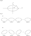
- This state is shown in Figs. 15(a) and 15(b) , where Fig. 15(a) is a graph showing the axial ratio characteristics, and Fig. 15(b) shows a polarization state at the respective frequency.
- the axial ratio is substantially 0 dB and is satisfactory at the designed frequency, that is, near the center frequency f0, but the axial ratio characteristic significantly degrades at f-, which is shifted to the - side, and at f+, which is shifted to the + side, with respect to the center frequency.
- circular polarization is obtained at the center frequency f0, but an elliptical polarization inclined to the left or the right is obtained and the axial ratio is significantly degraded at f- and f+.
- a sequential array antenna in which planar antennas with perturbation are sequentially arranged has been developed in recent years (see e.g., paragraph 0027 of Patent Document 1).
- Figs. 17(a) to 17(d) show the directional characteristics and the axial ratio characteristics of the sequential array antenna, where Figs. 17(a) and 17(b) show the state of the beam when the frequency f+ is used, and Figs.
- E 0 is the horizontal component of the circular polarization
- E ⁇ is the vertical component, where in the cases of frequency f+ and frequency f-, the beam direction is left and right opposite although the gain does not change and the axial ratio characteristics do not change in E 0 and E ⁇ , and furthermore, change exists in E ⁇ and E ⁇ when beam shifted in combination with the phase shifter, as shown in Figs. 17(b) and 17(d) .
- Figs. 19(a) to 19(d) show the directional characteristics of the phased array antenna, where Figs. 19(a) and 19(b) show the state of the beam when the frequency f+ is used, and Figs. 19(c) and 19(d) show the state of the beam when the frequency f- is used.
- the sequential array antenna or the phased array antenna is configured using a planar antenna element in which the individual antenna axial ratio band is low, the broadside direction maintains satisfactory axial ratio characteristics over a wide band regardless of the change in frequency but the directional direction fluctuates due to change in frequency in the sequential array antenna.
- the directional direction does not fluctuate due to change in frequency, but the axial ratio fluctuates due to change in frequency.
- the respective array antennas have advantages and disadvantages in the directional characteristics and the axial ratio band.
- the following method is known as a method for solving the problems of the background art.
- One method of improving the axial ratio band is a method of thickening the thickness of the substrate that configures the array antenna or lowering the substrate dielectric constant.
- Another method of improving the axial ratio band is a method of providing the power supply point at two regions, but such a method also arises a different problem in that the power supply circuit becomes complicating.
- Patent Document 1 Japanese Unexamined Patent Publication No. 09-98016
- the present invention has been devised to solve the problems described above, and an object thereof is to provide an array antenna in which a plurality of planar antenna elements with perturbation are linearly arranged, the array antenna having both excellent directional characteristics and axial ratio characteristics without changing a substrate or dimensions even when a frequency is changed.
- the present invention is directed to an array antenna in which a plurality of planar antenna elements with perturbation are linearly arranged, the array antenna including: a first sequential arrangement section in which antenna elements are sequentially arranged from a left end section to a center section; and a second sequential arrangement section in which antenna elements are sequentially arranged from a right end section to the center section; wherein the first sequential arrangement section and the second sequential arrangement section are symmetric.
- the method of applying perturbation to the planar antenna element includes a method of loading a degeneracy separation element by cutout (slit) and the like to a linear polarization patch antenna.
- the planar antenna generates circular polarization by loading the degeneracy separation element.
- the plurality of planar antenna elements with perturbation may be provided in an even number or an odd number. If including an odd number of antenna elements, the planar antenna element positioned at the center section is commonly used by the first sequential arrangement section and the second sequential arrangement section.
- Each of the planar antenna elements with perturbation may be a circular patch antenna or a square patch antenna.
- the planar antenna elements with perturbation configuring the first sequential arrangement section and the second sequential arrangement section may be spaced at equal or unequal intervals.
- the interval of each antenna element may be an equal interval or an unequal interval, but the symmetrical relationship in which the first sequential arrangement section matches the second sequential arrangement section when rotated 180 degrees and overlapped thereon needs to be satisfied.
- an array antenna in which a plurality of planar antenna elements with perturbation is linearly arranged, the array antenna including a first sequential arrangement section in which the antenna elements are arranged from the left end section to the center section and a second sequential arrangement section in which the antenna elements are arranged from the right end section to the center section, and the first sequential arrangement section and the second sequential arrangement section being symmetric. Both excellent directional characteristics and the axial ratio characteristics are obtained without changing a substrate or dimensions even when a frequency is changed.
- the arrangement of antenna elements in a conventional sequential array antenna is improved in an array antenna of the present invention based on the following theory so that both the directional characteristics and the axial ratio characteristics are satisfactory even when a usage channel is changed.
- the present inventors came to invent the array antenna of the present invention based on the following presumption. This will be described in detail below.
- Figs. 1(a) and 1(b) there is shown the electric field intensity in a ⁇ + direction and a ⁇ - direction when a beam is directed in a broadside direction under the following conditions in a array antenna in which a plurality of (N) antenna elements (antenna 1, antenna 2, ... antenna N) are linearly arranged.
- Fig. 1(a) shows the electric field in the ⁇ + direction, and the conditions thereof are as fellows.
- an excitation amplitude in the ⁇ (Theta) direction of each antenna element is E ⁇ n (first antenna element is E ⁇ 1 )
- a composite electric field in the ⁇ + direction is E ⁇ +
- a directional gain of each antenna element is D( ⁇ )
- a spacing of the antenna elements is d.
- An excitation phase ( ⁇ ) of each antenna element is the same.
- a composite electric field E 0+ is expressed with the following ⁇ equation 1>.
- Fig. 1(b) shows a case in which the beam is directed in the ⁇ - direction, and the conditions thereof are as follows.
- an excitation amplitude in the ⁇ (Theta) direction of each antenna element is E ⁇ n (first antenna element is E ⁇ 1 )
- a composite electric field in the ⁇ - direction is E ⁇ -
- a directional gain of each antenna element is D( ⁇ )
- a spacing of the antenna elements is d.
- An excitation phase ( ⁇ ) of each antenna element is the same.
- a composite electric field E ⁇ - is expressed with the following ⁇ equation 2>.
- ⁇ Equation 2> ⁇ Equation 2>
- the conditional equation [7] is schematically shown in Fig. 2 . In this case, the excitation amplitude from the left end section to the center section, and the excitation amplitude from the right end section to the center section are responded in order.
- each antenna element is sequentially arranged, the arrangement of each antenna element is assumed to satisfy the following conditional equation.
- ⁇ n n ⁇ 1 ⁇ / N n : n th antenna element , N : number of antenna elements (n: n th antenna element, N: number of antenna elements)
- the directional direction is symmetric if each antenna element is arranged in a special sequential arrangement, as will be described below.
- special sequential arrangement is referred to as "special sequential arrangement" in the present invention.
- Equation [7] is a conditional equation for obtaining a symmetric beam pattern in the array antenna, and thus a result in that the directional direction is symmetric is obtained by arranging the antenna elements in the special sequential arrangement so as to satisfy equation [11]. This is the same theory in the E ⁇ direction, where the condition of equation [7] is always satisfied even when the axial ratio characteristics due to frequency is changed.
- the axial ratio of the normal array is thus a : b.
- ⁇ n ⁇ (N-n+1)
- E( ⁇ 1) > E( ⁇ t) in the case of the special sequential arrangement.
- E( ⁇ MAX):E( ⁇ MIN) ⁇ a : b whereby degradation of the axial ratio is proven to be reduced by the special sequential arrangement.
- the difference in the directional direction and the degradation of the axial ratio can be improved, in particular, even when the usage frequency is shifted from the center frequency by the usage channel as in the RFID.
- the array antenna configured by the special sequential arrangement is the array antenna of the present invention.
- Figs. 6(a) and 6(b) are diagrams schematically showing the arrangement structure of the array antenna of the present invention, where Fig. 6(a) shows a case in which the number of antenna elements is an odd number and Fig. 6(b) shows a case in which the number of antenna elements is an even number.
- the array antenna is configured as in Fig. 6(a) .
- the array antenna has a plurality of antenna elements 10(1), 10(2), ... 20(1), 20(2), ... that are linearly arranged, where each antenna element is a circular patch antenna having one power supply point 11 or 21, and opposing cutouts 12 or 22 as perturbation.
- the structure of each antenna element is all the same, and only differs in the antenna direction.
- the power supply point 11 or 21, and the cutouts 12 or 22 are given a reference number only to the representative portion.
- the array antenna includes a first sequential arrangement portion S1 in which a plurality of antenna elements 10(1), 10(2), ... are sequentially arranged from the left end section to the center section, and a second sequential arrangement section S2 in which a plurality of antenna elements 20(1), 20(2), ... are sequentially arranged from the right end section to the center section, where the number of the whole antenna elements is an odd number.
- the antenna element 10(n) or 20(n) at the center section shown is commonly used by the first sequential arrangement section S1 and the second sequential arrangement section S2.
- the first sequential arrangement section S1 and the second sequential arrangement section S2 are in a symmetrical relationship.
- the symmetrical relationship means a relationship in which the first sequential arrangement section S1 matches the second sequential arrangement section S2 when rotated 180 degrees and overlapped thereon.
- this means that each antenna is arranged after being mechanically rotated to satisfy the equation ⁇ n (n-1) ⁇ /N (n: n th antenna element, N: number of antenna elements).
- the array antenna of the present invention is configured by an even number of antenna elements, as shown in Fig. 6(b) , where the structure of each antenna element is similar to the structure of the antenna element shown in Fig. 6(a) .
- the array antenna includes a first sequential arrangement portion S10 in which a plurality of antenna elements 10(1), 10(2), ... are sequentially arranged from the left end section to the center section, and a second sequential arrangement section S20 in which a plurality of antenna elements 20(1), 20(2), ... are sequentially arranged from the right end section to the center section, where the first sequential arrangement section S10 and the second sequential arrangement section S20 are in a symmetrical relationship, which is similar to the above.
- the directional direction does not fluctuate by the frequency and the axial ratio band also improves when configuring the array antenna by arranging the antenna elements in the special sequential arrangement.
- the results are as shown in Figs. 8(a) to 8(d).
- Figs. 8(a) to 8(d) correspond to Figs. 17(a) to 17(d) , and show the directional characteristics of the array antenna of the present invention shown in Fig. 7 .
- Figs. 8(a) to 8(d) correspond to Figs. 17(a) to 17(d)
- the beam direction is directed substantially the front direction and the directional characteristics does not fluctuate by change in frequency at both the frequency f+ and the frequency f-, as shown in Figs. 8(a) and 8(c) .
- the gain also barely changes at frequencies f+, f-, and the axial ratio band is also improved.
- the directional direction does not fluctuate by the change in frequency and the axial ratio band is also improved, as shown in Figs. 8(b) and 8(d) .
- the present inventors conducted a comparative experiment for when the antenna elements are arranged in the conventional sequential arrangement and for when arranged in the special sequential arrangement of the present invention, with the number of antenna elements changed between three and six.
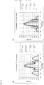
- the results are shown in Figs. 9(a) to 12(b) .
- the left side is for frequency f- and the right side is for frequency f+
- the vertical axis is the gain
- the horizontal axis is the angle.
- the special Etheta and the special Ephi are for the array antenna of the present invention
- sequential Etheta and the sequential Ephi are for the conventional sequential array antenna.
- the array antenna of the present invention having the above-described configuration has the interval of each antenna element set to an equal interval.
- the interval of the antenna elements may not necessarily be an equal interval.
- the present inventors performed a simulation while changing the interval of each antenna element.
- the antenna elements were arranged as in Figs. 13(a) and 13(b).
- Fig. 13(a) shows a case in which five antenna elements are arranged at equal intervals of 150 mm.
- Fig. 13(b) shows a case in which five antenna elements are arranged at equal intervals of 180 mm between the antenna element 10(1) and the antenna element 10(2) on the left end section and between the antenna element 20(1) and the antenna element 20(2) on the right end section, respectively.
- the antenna elements are arranged at equal intervals of 160 mm between the antenna element 10(2) and the antenna element 10(3) at the center section and between the antenna element 20(2) and the antenna element 20(3) at the center section, respectively, so that the antenna elements are arranged at uneven intervals as a whole.
Landscapes
- Variable-Direction Aerials And Aerial Arrays (AREA)
- Waveguide Aerials (AREA)
Claims (4)
- Antenne réseau séquentielle dans laquelle une pluralité d'éléments d'antenne plans (10(1), 10(2), 10(3), 20(1), 20(2), 20(3)), ayant chacun une perturbation sous forme de découpes, sont agencés selon un agencement linéaire, l'antenne réseau comprenant :une première section d'agencement séquentiel d'éléments d'antenne (10(1), 10(2), 10(3)) de la pluralité d'éléments d'antenne (10(1), 10(2), 10(3), 20(1), 20(2), 20(3)), qui sont séquentiellement agencés et tournés d'une section d'extrémité gauche à une section centrale de l'agencement linéaire ; etune seconde section d'agencement séquentiel d'éléments d'antenne (20(1), 20(2), 20(3)) de la pluralité d'éléments d'antenne (10(1), 10(2), 10(3), 20(1), 20(2), 20(3)) qui sont séquentiellement agencés et tournés d'une section d'extrémité droite à la section centrale de l'agencement linéaire ; caractérisée en ce quela première section d'agencement séquentiel et la seconde section d'agencement séquentiel sont symétriques de sorte que la première section d'agencement séquentiel corresponde à la seconde section d'agencement séquentiel lorsqu'elle est tournée de 180 degrés et superposée sur la seconde section d'agencement séquentiel.
- Antenne réseau selon la revendication 1, dans laquelle la pluralité d'éléments d'antenne plans (10(1), 10(2), 10(3), 20(1), 20(2), 20(3)) avec une perturbation sont fournis en un nombre pair ou en un nombre impair.
- Antenne réseau selon la revendication 1 ou 2, dans laquelle chacun des éléments d'antenne plans (10(1), 10(2), 10(3), 20(1), 20(2), 20(3)) avec une perturbation est une antenne patch circulaire ou une antenne patch carrée.
- Antenne réseau selon l'une des revendications 1 ou 3, dans laquelle les éléments d'antenne plans (10(1), 10(2), 10(3), 20(1), 20(2), 20(3)) avec une perturbation configurant la première section d'agencement séquentiel et la seconde section d'agencement séquentiel sont espacés à intervalles égaux ou inégaux.
Applications Claiming Priority (2)
| Application Number | Priority Date | Filing Date | Title |
|---|---|---|---|
| JP2007131608 | 2007-05-17 | ||
| PCT/JP2008/054724 WO2008142900A1 (fr) | 2007-05-17 | 2008-03-14 | Antenne réseau |
Publications (3)
| Publication Number | Publication Date |
|---|---|
| EP2148390A1 EP2148390A1 (fr) | 2010-01-27 |
| EP2148390A4 EP2148390A4 (fr) | 2014-01-08 |
| EP2148390B1 true EP2148390B1 (fr) | 2017-06-21 |
Family
ID=40031618
Family Applications (1)
| Application Number | Title | Priority Date | Filing Date |
|---|---|---|---|
| EP08722120.6A Active EP2148390B1 (fr) | 2007-05-17 | 2008-03-14 | Antenne réseau |
Country Status (5)
| Country | Link |
|---|---|
| US (1) | US8289214B2 (fr) |
| EP (1) | EP2148390B1 (fr) |
| JP (1) | JP5024638B2 (fr) |
| CN (1) | CN101682125B (fr) |
| WO (1) | WO2008142900A1 (fr) |
Families Citing this family (23)
| Publication number | Priority date | Publication date | Assignee | Title |
|---|---|---|---|---|
| CN101682125B (zh) | 2007-05-17 | 2013-03-27 | 欧姆龙株式会社 | 阵列天线 |
| WO2010137713A1 (fr) * | 2009-05-29 | 2010-12-02 | 株式会社エヌ・ティ・ティ・ドコモ | Reflectarray |
| TWI557993B (zh) * | 2012-09-03 | 2016-11-11 | 鴻海精密工業股份有限公司 | 陣列天線及其圓極化天線 |
| US9179336B2 (en) | 2013-02-19 | 2015-11-03 | Mimosa Networks, Inc. | WiFi management interface for microwave radio and reset to factory defaults |
| US9930592B2 (en) | 2013-02-19 | 2018-03-27 | Mimosa Networks, Inc. | Systems and methods for directing mobile device connectivity |
| WO2014138292A1 (fr) | 2013-03-06 | 2014-09-12 | Mimosa Networks, Inc. | Enceinte pour radio, antenne à réflecteur parabolique, et blindages de lobe secondaire |
| WO2014137370A1 (fr) | 2013-03-06 | 2014-09-12 | Mimosa Networks, Inc. | Appareil étanche à l'eau pour câbles et interfaces de câbles |
| US10742275B2 (en) | 2013-03-07 | 2020-08-11 | Mimosa Networks, Inc. | Quad-sector antenna using circular polarization |
| US9191081B2 (en) | 2013-03-08 | 2015-11-17 | Mimosa Networks, Inc. | System and method for dual-band backhaul radio |
| US9295103B2 (en) | 2013-05-30 | 2016-03-22 | Mimosa Networks, Inc. | Wireless access points providing hybrid 802.11 and scheduled priority access communications |
| US10938110B2 (en) * | 2013-06-28 | 2021-03-02 | Mimosa Networks, Inc. | Ellipticity reduction in circularly polarized array antennas |
| US9001689B1 (en) | 2014-01-24 | 2015-04-07 | Mimosa Networks, Inc. | Channel optimization in half duplex communications systems |
| US9780892B2 (en) | 2014-03-05 | 2017-10-03 | Mimosa Networks, Inc. | System and method for aligning a radio using an automated audio guide |
| US9998246B2 (en) | 2014-03-13 | 2018-06-12 | Mimosa Networks, Inc. | Simultaneous transmission on shared channel |
| US10958332B2 (en) | 2014-09-08 | 2021-03-23 | Mimosa Networks, Inc. | Wi-Fi hotspot repeater |
| JP6456758B2 (ja) * | 2015-04-09 | 2019-01-23 | 日本電信電話株式会社 | 分散アレーアンテナ装置およびサイドローブ抑制方法 |
| WO2017123558A1 (fr) | 2016-01-11 | 2017-07-20 | Mimosa Networks, Inc. | Antenne montée sur une carte de circuit imprimé et interface de guide d'ondes |
| US11251539B2 (en) | 2016-07-29 | 2022-02-15 | Airspan Ip Holdco Llc | Multi-band access point antenna array |
| US10511074B2 (en) | 2018-01-05 | 2019-12-17 | Mimosa Networks, Inc. | Higher signal isolation solutions for printed circuit board mounted antenna and waveguide interface |
| WO2019168800A1 (fr) | 2018-03-02 | 2019-09-06 | Mimosa Networks, Inc. | Système d'antenne à polarisation orthogonale omnidirectionnelle pour applications mimo |
| US11289821B2 (en) | 2018-09-11 | 2022-03-29 | Air Span Ip Holdco Llc | Sector antenna systems and methods for providing high gain and high side-lobe rejection |
| CN114616721B (zh) * | 2019-10-21 | 2025-09-26 | 株式会社村田制作所 | 圆极化阵列天线装置 |
| CN111641049A (zh) * | 2020-05-20 | 2020-09-08 | 广州程星通信科技有限公司 | 一种相控阵切换波束控制方法、系统、装置及存储介质 |
Family Cites Families (10)
| Publication number | Priority date | Publication date | Assignee | Title |
|---|---|---|---|---|
| JPS59178002A (ja) * | 1983-03-29 | 1984-10-09 | Radio Res Lab | 円偏波アンテナ |
| GB8624984D0 (en) * | 1986-10-17 | 1986-11-19 | Emi Plc Thorn | Antenna |
| US5181042A (en) * | 1988-05-13 | 1993-01-19 | Yagi Antenna Co., Ltd. | Microstrip array antenna |
| KR920002227B1 (ko) * | 1988-05-13 | 1992-03-20 | 야기 안테나 가부시끼가이샤 | 마이크로스트립 어레이 안테나 |
| GB8904303D0 (en) * | 1989-02-24 | 1989-04-12 | Marconi Co Ltd | Dual slot antenna |
| JPH0831742B2 (ja) | 1989-11-08 | 1996-03-27 | 三菱電機株式会社 | アンテナ装置 |
| JP3169371B2 (ja) * | 1990-06-04 | 2001-05-21 | ソニー株式会社 | 平面アレイアンテナ |
| KR0147035B1 (ko) | 1993-07-31 | 1998-08-17 | 배순훈 | 개선된 헤리컬 와이어 배열 평면안테나 |
| JPH0998016A (ja) | 1995-10-02 | 1997-04-08 | Mitsubishi Electric Corp | マイクロストリップアンテナ |
| CN101682125B (zh) | 2007-05-17 | 2013-03-27 | 欧姆龙株式会社 | 阵列天线 |
-
2008
- 2008-03-14 CN CN2008800157890A patent/CN101682125B/zh active Active
- 2008-03-14 EP EP08722120.6A patent/EP2148390B1/fr active Active
- 2008-03-14 WO PCT/JP2008/054724 patent/WO2008142900A1/fr not_active Ceased
- 2008-03-14 US US12/451,478 patent/US8289214B2/en active Active
- 2008-03-14 JP JP2009515105A patent/JP5024638B2/ja active Active
Also Published As
| Publication number | Publication date |
|---|---|
| US8289214B2 (en) | 2012-10-16 |
| EP2148390A4 (fr) | 2014-01-08 |
| CN101682125B (zh) | 2013-03-27 |
| JP5024638B2 (ja) | 2012-09-12 |
| JPWO2008142900A1 (ja) | 2010-08-05 |
| US20100171665A1 (en) | 2010-07-08 |
| WO2008142900A1 (fr) | 2008-11-27 |
| EP2148390A1 (fr) | 2010-01-27 |
| CN101682125A (zh) | 2010-03-24 |
Similar Documents
| Publication | Publication Date | Title |
|---|---|---|
| EP2148390B1 (fr) | Antenne réseau | |
| US9698479B2 (en) | Two-dimensionally electronically-steerable artificial impedance surface antenna | |
| JP6365680B2 (ja) | アンテナモジュール | |
| JP5718315B2 (ja) | アンテナ及び一体化アンテナ | |
| US11894624B2 (en) | Slotted patch antenna | |
| US20220302596A1 (en) | Parallel plate slot array antenna with defined beam squint | |
| EP1509971A1 (fr) | Antenne secteur a guide d'ondes creux | |
| JP2009212727A (ja) | レーダ用アンテナ | |
| JP4531033B2 (ja) | リッジ導波路中央給電スロットアレーアンテナ | |
| JP2009100253A (ja) | レーダ装置用アンテナ | |
| EP3331092B1 (fr) | Circuit d'alimentation | |
| US6924765B2 (en) | Microstrip patch array antenna for suppressing side lobes | |
| CN212571355U (zh) | 圆极化超表面天线 | |
| EP3731344A1 (fr) | Dispositif d'antenne | |
| US10944185B2 (en) | Wideband phased mobile antenna array devices, systems, and methods | |
| JPH11266118A (ja) | パッチアレイアンテナ | |
| JP2001267835A (ja) | 円偏波マイクロストリップアンテナ及び同アンテナに適用される交差偏波成分低減方法 | |
| WO2019202893A1 (fr) | Antenne | |
| JP6204229B2 (ja) | ループアンテナ | |
| US12476374B2 (en) | Antenna | |
| US20250379353A1 (en) | Multiantenna | |
| EP4550579A1 (fr) | Élément d'antenne, substrat d'antenne et module d'antenne | |
| WO2023176093A1 (fr) | Dispositif d'antenne | |
| JP2010045649A (ja) | アンテナ装置 | |
| JPH11274838A (ja) | アクティブフェーズドアレーアンテナ |
Legal Events
| Date | Code | Title | Description |
|---|---|---|---|
| PUAI | Public reference made under article 153(3) epc to a published international application that has entered the european phase |
Free format text: ORIGINAL CODE: 0009012 |
|
| 17P | Request for examination filed |
Effective date: 20091207 |
|
| AK | Designated contracting states |
Kind code of ref document: A1 Designated state(s): AT BE BG CH CY CZ DE DK EE ES FI FR GB GR HR HU IE IS IT LI LT LU LV MC MT NL NO PL PT RO SE SI SK TR |
|
| AX | Request for extension of the european patent |
Extension state: AL BA MK RS |
|
| DAX | Request for extension of the european patent (deleted) | ||
| A4 | Supplementary search report drawn up and despatched |
Effective date: 20131209 |
|
| RIC1 | Information provided on ipc code assigned before grant |
Ipc: H01Q 9/04 20060101ALN20131203BHEP Ipc: H01Q 21/24 20060101AFI20131203BHEP Ipc: H01Q 21/06 20060101ALI20131203BHEP |
|
| GRAP | Despatch of communication of intention to grant a patent |
Free format text: ORIGINAL CODE: EPIDOSNIGR1 |
|
| STAA | Information on the status of an ep patent application or granted ep patent |
Free format text: STATUS: GRANT OF PATENT IS INTENDED |
|
| RIC1 | Information provided on ipc code assigned before grant |
Ipc: H01Q 21/24 20060101AFI20161212BHEP Ipc: H01Q 9/04 20060101ALN20161212BHEP Ipc: H01Q 21/06 20060101ALI20161212BHEP |
|
| INTG | Intention to grant announced |
Effective date: 20170103 |
|
| GRAS | Grant fee paid |
Free format text: ORIGINAL CODE: EPIDOSNIGR3 |
|
| GRAA | (expected) grant |
Free format text: ORIGINAL CODE: 0009210 |
|
| STAA | Information on the status of an ep patent application or granted ep patent |
Free format text: STATUS: THE PATENT HAS BEEN GRANTED |
|
| AK | Designated contracting states |
Kind code of ref document: B1 Designated state(s): AT BE BG CH CY CZ DE DK EE ES FI FR GB GR HR HU IE IS IT LI LT LU LV MC MT NL NO PL PT RO SE SI SK TR |
|
| REG | Reference to a national code |
Ref country code: GB Ref legal event code: FG4D |
|
| REG | Reference to a national code |
Ref country code: CH Ref legal event code: EP |
|
| REG | Reference to a national code |
Ref country code: IE Ref legal event code: FG4D |
|
| REG | Reference to a national code |
Ref country code: AT Ref legal event code: REF Ref document number: 903711 Country of ref document: AT Kind code of ref document: T Effective date: 20170715 |
|
| REG | Reference to a national code |
Ref country code: DE Ref legal event code: R096 Ref document number: 602008050765 Country of ref document: DE |
|
| REG | Reference to a national code |
Ref country code: NL Ref legal event code: MP Effective date: 20170621 |
|
| PG25 | Lapsed in a contracting state [announced via postgrant information from national office to epo] |
Ref country code: FI Free format text: LAPSE BECAUSE OF FAILURE TO SUBMIT A TRANSLATION OF THE DESCRIPTION OR TO PAY THE FEE WITHIN THE PRESCRIBED TIME-LIMIT Effective date: 20170621 Ref country code: LT Free format text: LAPSE BECAUSE OF FAILURE TO SUBMIT A TRANSLATION OF THE DESCRIPTION OR TO PAY THE FEE WITHIN THE PRESCRIBED TIME-LIMIT Effective date: 20170621 Ref country code: HR Free format text: LAPSE BECAUSE OF FAILURE TO SUBMIT A TRANSLATION OF THE DESCRIPTION OR TO PAY THE FEE WITHIN THE PRESCRIBED TIME-LIMIT Effective date: 20170621 Ref country code: NO Free format text: LAPSE BECAUSE OF FAILURE TO SUBMIT A TRANSLATION OF THE DESCRIPTION OR TO PAY THE FEE WITHIN THE PRESCRIBED TIME-LIMIT Effective date: 20170921 Ref country code: GR Free format text: LAPSE BECAUSE OF FAILURE TO SUBMIT A TRANSLATION OF THE DESCRIPTION OR TO PAY THE FEE WITHIN THE PRESCRIBED TIME-LIMIT Effective date: 20170922 |
|
| REG | Reference to a national code |
Ref country code: LT Ref legal event code: MG4D |
|
| REG | Reference to a national code |
Ref country code: AT Ref legal event code: MK05 Ref document number: 903711 Country of ref document: AT Kind code of ref document: T Effective date: 20170621 |
|
| PG25 | Lapsed in a contracting state [announced via postgrant information from national office to epo] |
Ref country code: SE Free format text: LAPSE BECAUSE OF FAILURE TO SUBMIT A TRANSLATION OF THE DESCRIPTION OR TO PAY THE FEE WITHIN THE PRESCRIBED TIME-LIMIT Effective date: 20170621 Ref country code: LV Free format text: LAPSE BECAUSE OF FAILURE TO SUBMIT A TRANSLATION OF THE DESCRIPTION OR TO PAY THE FEE WITHIN THE PRESCRIBED TIME-LIMIT Effective date: 20170621 Ref country code: BG Free format text: LAPSE BECAUSE OF FAILURE TO SUBMIT A TRANSLATION OF THE DESCRIPTION OR TO PAY THE FEE WITHIN THE PRESCRIBED TIME-LIMIT Effective date: 20170921 Ref country code: NL Free format text: LAPSE BECAUSE OF FAILURE TO SUBMIT A TRANSLATION OF THE DESCRIPTION OR TO PAY THE FEE WITHIN THE PRESCRIBED TIME-LIMIT Effective date: 20170621 |
|
| PG25 | Lapsed in a contracting state [announced via postgrant information from national office to epo] |
Ref country code: SK Free format text: LAPSE BECAUSE OF FAILURE TO SUBMIT A TRANSLATION OF THE DESCRIPTION OR TO PAY THE FEE WITHIN THE PRESCRIBED TIME-LIMIT Effective date: 20170621 Ref country code: CZ Free format text: LAPSE BECAUSE OF FAILURE TO SUBMIT A TRANSLATION OF THE DESCRIPTION OR TO PAY THE FEE WITHIN THE PRESCRIBED TIME-LIMIT Effective date: 20170621 Ref country code: AT Free format text: LAPSE BECAUSE OF FAILURE TO SUBMIT A TRANSLATION OF THE DESCRIPTION OR TO PAY THE FEE WITHIN THE PRESCRIBED TIME-LIMIT Effective date: 20170621 Ref country code: RO Free format text: LAPSE BECAUSE OF FAILURE TO SUBMIT A TRANSLATION OF THE DESCRIPTION OR TO PAY THE FEE WITHIN THE PRESCRIBED TIME-LIMIT Effective date: 20170621 Ref country code: EE Free format text: LAPSE BECAUSE OF FAILURE TO SUBMIT A TRANSLATION OF THE DESCRIPTION OR TO PAY THE FEE WITHIN THE PRESCRIBED TIME-LIMIT Effective date: 20170621 |
|
| PG25 | Lapsed in a contracting state [announced via postgrant information from national office to epo] |
Ref country code: ES Free format text: LAPSE BECAUSE OF FAILURE TO SUBMIT A TRANSLATION OF THE DESCRIPTION OR TO PAY THE FEE WITHIN THE PRESCRIBED TIME-LIMIT Effective date: 20170621 Ref country code: PL Free format text: LAPSE BECAUSE OF FAILURE TO SUBMIT A TRANSLATION OF THE DESCRIPTION OR TO PAY THE FEE WITHIN THE PRESCRIBED TIME-LIMIT Effective date: 20170621 Ref country code: IT Free format text: LAPSE BECAUSE OF FAILURE TO SUBMIT A TRANSLATION OF THE DESCRIPTION OR TO PAY THE FEE WITHIN THE PRESCRIBED TIME-LIMIT Effective date: 20170621 Ref country code: IS Free format text: LAPSE BECAUSE OF FAILURE TO SUBMIT A TRANSLATION OF THE DESCRIPTION OR TO PAY THE FEE WITHIN THE PRESCRIBED TIME-LIMIT Effective date: 20171021 |
|
| REG | Reference to a national code |
Ref country code: DE Ref legal event code: R097 Ref document number: 602008050765 Country of ref document: DE |
|
| PLBE | No opposition filed within time limit |
Free format text: ORIGINAL CODE: 0009261 |
|
| STAA | Information on the status of an ep patent application or granted ep patent |
Free format text: STATUS: NO OPPOSITION FILED WITHIN TIME LIMIT |
|
| PG25 | Lapsed in a contracting state [announced via postgrant information from national office to epo] |
Ref country code: DK Free format text: LAPSE BECAUSE OF FAILURE TO SUBMIT A TRANSLATION OF THE DESCRIPTION OR TO PAY THE FEE WITHIN THE PRESCRIBED TIME-LIMIT Effective date: 20170621 |
|
| 26N | No opposition filed |
Effective date: 20180322 |
|
| PG25 | Lapsed in a contracting state [announced via postgrant information from national office to epo] |
Ref country code: SI Free format text: LAPSE BECAUSE OF FAILURE TO SUBMIT A TRANSLATION OF THE DESCRIPTION OR TO PAY THE FEE WITHIN THE PRESCRIBED TIME-LIMIT Effective date: 20170621 |
|
| REG | Reference to a national code |
Ref country code: CH Ref legal event code: PL |
|
| GBPC | Gb: european patent ceased through non-payment of renewal fee |
Effective date: 20180314 |
|
| PG25 | Lapsed in a contracting state [announced via postgrant information from national office to epo] |
Ref country code: MC Free format text: LAPSE BECAUSE OF FAILURE TO SUBMIT A TRANSLATION OF THE DESCRIPTION OR TO PAY THE FEE WITHIN THE PRESCRIBED TIME-LIMIT Effective date: 20170621 |
|
| REG | Reference to a national code |
Ref country code: BE Ref legal event code: MM Effective date: 20180331 |
|
| REG | Reference to a national code |
Ref country code: IE Ref legal event code: MM4A |
|
| PG25 | Lapsed in a contracting state [announced via postgrant information from national office to epo] |
Ref country code: LU Free format text: LAPSE BECAUSE OF NON-PAYMENT OF DUE FEES Effective date: 20180314 |
|
| PG25 | Lapsed in a contracting state [announced via postgrant information from national office to epo] |
Ref country code: IE Free format text: LAPSE BECAUSE OF NON-PAYMENT OF DUE FEES Effective date: 20180314 |
|
| PG25 | Lapsed in a contracting state [announced via postgrant information from national office to epo] |
Ref country code: BE Free format text: LAPSE BECAUSE OF NON-PAYMENT OF DUE FEES Effective date: 20180331 Ref country code: CH Free format text: LAPSE BECAUSE OF NON-PAYMENT OF DUE FEES Effective date: 20180331 Ref country code: GB Free format text: LAPSE BECAUSE OF NON-PAYMENT OF DUE FEES Effective date: 20180314 Ref country code: LI Free format text: LAPSE BECAUSE OF NON-PAYMENT OF DUE FEES Effective date: 20180331 |
|
| PG25 | Lapsed in a contracting state [announced via postgrant information from national office to epo] |
Ref country code: FR Free format text: LAPSE BECAUSE OF NON-PAYMENT OF DUE FEES Effective date: 20180331 |
|
| PG25 | Lapsed in a contracting state [announced via postgrant information from national office to epo] |
Ref country code: MT Free format text: LAPSE BECAUSE OF NON-PAYMENT OF DUE FEES Effective date: 20180314 |
|
| PG25 | Lapsed in a contracting state [announced via postgrant information from national office to epo] |
Ref country code: TR Free format text: LAPSE BECAUSE OF FAILURE TO SUBMIT A TRANSLATION OF THE DESCRIPTION OR TO PAY THE FEE WITHIN THE PRESCRIBED TIME-LIMIT Effective date: 20170621 |
|
| PG25 | Lapsed in a contracting state [announced via postgrant information from national office to epo] |
Ref country code: HU Free format text: LAPSE BECAUSE OF FAILURE TO SUBMIT A TRANSLATION OF THE DESCRIPTION OR TO PAY THE FEE WITHIN THE PRESCRIBED TIME-LIMIT; INVALID AB INITIO Effective date: 20080314 Ref country code: PT Free format text: LAPSE BECAUSE OF FAILURE TO SUBMIT A TRANSLATION OF THE DESCRIPTION OR TO PAY THE FEE WITHIN THE PRESCRIBED TIME-LIMIT Effective date: 20170621 |
|
| PG25 | Lapsed in a contracting state [announced via postgrant information from national office to epo] |
Ref country code: CY Free format text: LAPSE BECAUSE OF FAILURE TO SUBMIT A TRANSLATION OF THE DESCRIPTION OR TO PAY THE FEE WITHIN THE PRESCRIBED TIME-LIMIT Effective date: 20170621 |
|
| PGFP | Annual fee paid to national office [announced via postgrant information from national office to epo] |
Ref country code: DE Payment date: 20250319 Year of fee payment: 18 |