EP2149074B1 - Elektronisch gesteuerte uhr - Google Patents
Elektronisch gesteuerte uhr Download PDFInfo
- Publication number
- EP2149074B1 EP2149074B1 EP08747898A EP08747898A EP2149074B1 EP 2149074 B1 EP2149074 B1 EP 2149074B1 EP 08747898 A EP08747898 A EP 08747898A EP 08747898 A EP08747898 A EP 08747898A EP 2149074 B1 EP2149074 B1 EP 2149074B1
- Authority
- EP
- European Patent Office
- Prior art keywords
- watch
- leds
- ring
- watch according
- display
- Prior art date
- Legal status (The legal status is an assumption and is not a legal conclusion. Google has not performed a legal analysis and makes no representation as to the accuracy of the status listed.)
- Not-in-force
Links
- 238000009826 distribution Methods 0.000 claims abstract description 4
- 239000000463 material Substances 0.000 claims description 12
- 239000004033 plastic Substances 0.000 claims description 11
- 229920003023 plastic Polymers 0.000 claims description 11
- 230000003287 optical effect Effects 0.000 claims description 7
- 229910052751 metal Inorganic materials 0.000 claims description 5
- 239000002184 metal Substances 0.000 claims description 5
- 239000012780 transparent material Substances 0.000 claims description 5
- 210000000707 wrist Anatomy 0.000 claims description 5
- 229910000831 Steel Inorganic materials 0.000 claims description 4
- 230000001133 acceleration Effects 0.000 claims description 4
- 239000010959 steel Substances 0.000 claims description 4
- 239000003086 colorant Substances 0.000 claims description 3
- 238000010079 rubber tapping Methods 0.000 claims description 2
- 238000001228 spectrum Methods 0.000 claims description 2
- XMQFTWRPUQYINF-UHFFFAOYSA-N bensulfuron-methyl Chemical compound COC(=O)C1=CC=CC=C1CS(=O)(=O)NC(=O)NC1=NC(OC)=CC(OC)=N1 XMQFTWRPUQYINF-UHFFFAOYSA-N 0.000 claims 1
- 210000004247 hand Anatomy 0.000 description 9
- 238000000034 method Methods 0.000 description 8
- 230000009471 action Effects 0.000 description 6
- 239000011521 glass Substances 0.000 description 6
- 238000004382 potting Methods 0.000 description 6
- 230000008859 change Effects 0.000 description 4
- 229920000642 polymer Polymers 0.000 description 4
- 239000003990 capacitor Substances 0.000 description 3
- 150000001875 compounds Chemical class 0.000 description 3
- 239000013013 elastic material Substances 0.000 description 3
- 239000002096 quantum dot Substances 0.000 description 3
- 239000010453 quartz Substances 0.000 description 3
- 230000002441 reversible effect Effects 0.000 description 3
- VYPSYNLAJGMNEJ-UHFFFAOYSA-N silicon dioxide Inorganic materials O=[Si]=O VYPSYNLAJGMNEJ-UHFFFAOYSA-N 0.000 description 3
- 238000010276 construction Methods 0.000 description 2
- 230000000694 effects Effects 0.000 description 2
- 230000005484 gravity Effects 0.000 description 2
- 238000004519 manufacturing process Methods 0.000 description 2
- 239000002086 nanomaterial Substances 0.000 description 2
- 230000008569 process Effects 0.000 description 2
- 230000002123 temporal effect Effects 0.000 description 2
- WHXSMMKQMYFTQS-UHFFFAOYSA-N Lithium Chemical compound [Li] WHXSMMKQMYFTQS-UHFFFAOYSA-N 0.000 description 1
- 239000013543 active substance Substances 0.000 description 1
- 239000000853 adhesive Substances 0.000 description 1
- 238000004026 adhesive bonding Methods 0.000 description 1
- 230000001070 adhesive effect Effects 0.000 description 1
- 210000003423 ankle Anatomy 0.000 description 1
- 230000004888 barrier function Effects 0.000 description 1
- 238000005452 bending Methods 0.000 description 1
- 230000005540 biological transmission Effects 0.000 description 1
- 230000004397 blinking Effects 0.000 description 1
- 239000012141 concentrate Substances 0.000 description 1
- 239000004020 conductor Substances 0.000 description 1
- 230000003247 decreasing effect Effects 0.000 description 1
- 238000010586 diagram Methods 0.000 description 1
- 239000008393 encapsulating agent Substances 0.000 description 1
- 238000005516 engineering process Methods 0.000 description 1
- 230000003760 hair shine Effects 0.000 description 1
- 238000005286 illumination Methods 0.000 description 1
- 238000007373 indentation Methods 0.000 description 1
- 239000010410 layer Substances 0.000 description 1
- 229910052744 lithium Inorganic materials 0.000 description 1
- 239000003550 marker Substances 0.000 description 1
- 238000005259 measurement Methods 0.000 description 1
- 230000007246 mechanism Effects 0.000 description 1
- 238000002844 melting Methods 0.000 description 1
- 230000008018 melting Effects 0.000 description 1
- 150000002739 metals Chemical class 0.000 description 1
- 229910001172 neodymium magnet Inorganic materials 0.000 description 1
- 239000003973 paint Substances 0.000 description 1
- 239000000049 pigment Substances 0.000 description 1
- BASFCYQUMIYNBI-UHFFFAOYSA-N platinum Chemical compound [Pt] BASFCYQUMIYNBI-UHFFFAOYSA-N 0.000 description 1
- 239000011241 protective layer Substances 0.000 description 1
- 230000009467 reduction Effects 0.000 description 1
- 230000011514 reflex Effects 0.000 description 1
- 230000003763 resistance to breakage Effects 0.000 description 1
- 230000033764 rhythmic process Effects 0.000 description 1
- 230000035939 shock Effects 0.000 description 1
- 238000005476 soldering Methods 0.000 description 1
- 239000004575 stone Substances 0.000 description 1
- 230000007704 transition Effects 0.000 description 1
- 230000001960 triggered effect Effects 0.000 description 1
- 230000000007 visual effect Effects 0.000 description 1
- XLYOFNOQVPJJNP-UHFFFAOYSA-N water Substances O XLYOFNOQVPJJNP-UHFFFAOYSA-N 0.000 description 1
- 239000002023 wood Substances 0.000 description 1
Images



Classifications
-
- G—PHYSICS
- G04—HOROLOGY
- G04G—ELECTRONIC TIME-PIECES
- G04G9/00—Visual time or date indication means
- G04G9/02—Visual time or date indication means by selecting desired characters out of a number of characters or by selecting indicating elements the position of which represent the time, e.g. by using multiplexing techniques
- G04G9/04—Visual time or date indication means by selecting desired characters out of a number of characters or by selecting indicating elements the position of which represent the time, e.g. by using multiplexing techniques by controlling light sources, e.g. electroluminescent diodes
-
- G—PHYSICS
- G04—HOROLOGY
- G04G—ELECTRONIC TIME-PIECES
- G04G17/00—Structural details; Housings
- G04G17/08—Housings
- G04G17/083—Watches distributed over several housings
-
- G—PHYSICS
- G04—HOROLOGY
- G04G—ELECTRONIC TIME-PIECES
- G04G9/00—Visual time or date indication means
- G04G9/0017—Visual time or date indication means in which the light emitting display elements may be activated at will or are controlled in accordance with the ambient light
Definitions
- the invention relates to an electronically controlled clock whose housing and display panel are formed as a ring, wherein the clock displays are formed by circulating on the ring luminous points, and wherein at least one annular row of at least 60 light-emitting diodes (LEDs) is provided, wherein by the luminous state of individual LEDs at least the time parameters "hour” and “minute”, preferably in addition to the time parameter "second" are indexable, and serving as an annular display panel electronic board is arranged on one of the annular end faces.
- LEDs light-emitting diodes
- Portable watches in ring form are from the WO 01/88638 A1 known.
- timer, time display and voltage source are integrated into a bangle, wherein the time display extends over part of the hoop circumference and consists of electronically controllable digits.
- the essential feature of a clock of this kind lies in the artistic combination and structural standardization of bracelet and watch case.
- the CH 613 599 G A3 and the NL C 1012053 show that the analog clock pointers can be replaced by electric bulbs.
- the time indication is there by means of circularly arranged light-emitting diodes (LEDs), which represent the positions of the tips of hour and minute hands.
- LEDs represent the positions of the tips of hour and minute hands.
- the light state of one of these LEDs indicates the position of a defined pointer.
- Both revelations have in common that both the watch case and conventional flat cylinder or discs are formed, wherein the number for the hour-display LEDs with twelve only capable of displaying whole hours. An intermediate position of the hour, as it happens with analog clocks and is also desired for easier time reading is not possible there.
- the GB 2 162 663 A discloses a wristwatch with an annular watch case, in which circularly arranged LEDs replace the position of analog clock hands in the lighted state. It displays minutes and hours in two separate LED circles. This forces a widening of the housing ring and leads to an appearance of the entire clock, which is closer to a conventional watch case than an annular clock. Moreover, in the GB 2 162 663 A provided that the hour LEDs are made larger than the minute LEDs, so that the hour LEDs simultaneously act as permanent hour indices. This is economically disadvantageous because it increases the number of work steps required to make the watch.
- the DE 202 08 330 U1 discloses a conventional disc-shaped watch case that instead of analogous hands on a dial, has a ring of 60 LEDs whose illumination represents the tips of analog hour hands and minute hands.
- 12 fixed hours LEDs are provided which, firstly, are larger than the intermediate ones 48-minute LEDs are performed, resulting in an increased number of steps in the manufacture of the watch case; secondly, a fixed hour LED will flash for a full hour, while the tip of an analog hour hand would move continuously from one of the 12 markers to the next.
- the doctrine of DE 3 806 561 A1 consists in a method to implement a digital timing in an electrically effected and seemingly analog time display.
- circular, square or triangular watch cases are disclosed, the middle parts of which are left free, the time indication being effected by means of the lighting states of three concentric LED rows in replacement of the positions of analog second, minute and hour hands.
- this design shows analog as the GB 2 162 663 A the disadvantage of spending a large number of LEDs to require a wide ring band as a watch case and to produce a clumsy appearance.
- the GB 2 384 063 A adds to the prior art a watch with an annular housing that can be worn as a (finger) ring or bracelet.
- the time is indicated by the position of two hourly and minute-by-round indicators circulating around the circumference of the ring, or by a central ring with printed numerical sequence passing by an immovable indicator.
- the GB 2 409 295 A shows a watch with an annular housing that can be worn as a finger, ankle ring or a bracelet.
- Indicators for the time are either the circulating light of an LED of an LED ring or the circulating light of two LEDs of two LED rings.
- Analogous to the previously mentioned GB 2 384 063 A the LEDs are in the periphery of the ring.
- Analogous to the GB 2 218 895 A of the GB 2,162 663 A as well as the DE 3 806 561 A1
- two separate LED rings are needed.
- the invention is therefore based on the goal to provide a clock of the type mentioned preferably as a wristwatch, the ring thickness in relation to the ring diameter turns out to be as small as possible, the minute, hour and second indication is on a single ring of LEDs. That is, it is only provided an LED formed ring, which is arranged in the ring of the watch case.
- the light emitting diodes have an equal size among each other, wherein the time parameter "hour” can be displayed on all LEDs, and that the displays of hours, minutes and seconds by the light pattern and / or the luminous color and / or the brightness and / or the luminous distribution to a plurality of adjacent LEDs differ from each other.
- the indications of hours, minutes and seconds differ by the luminous pattern and / or the luminous color and / or the brightness and / or the luminous distribution on a plurality of adjacent LEDs from each other.
- the watch case consists of at least one annular piece having a groove in which the inserted and fixed display electronics is sealed with a transparent material.
- Fig. 1 and 2 lie in the groove 13 of a thin steel ring 1 embedded electronic boards 2, which are strung together a multiple of 12, in particular of 60 preferably multi-colored light emitting diodes (LEDs) 16, which can display hours, minutes, seconds and more information.
- LEDs light emitting diodes
- Various parameters are displayed here on a single circle of LEDs; the distinction is made by the luminous color, the brightness, the number of luminous LEDs or the graphic light pattern or a temporal change of the above parameters (eg flashing, pulsating, twinkling, Fig. 3a to 3e ).
- the width of the ring thus depends only on the technically feasible thickness of the lighting elements and can thus be less than all previously known solutions.
- the luminous colors and shapes of display parameters are expediently chosen so that overlaps do not mask of parameters.
- These display symbols can overlap with each other and yet be recognized individually. It is also possible to distinguish the parameters by other luminous colors. By using the number of dots, the luminous color and the blinking rhythm for coding, many parameters can be displayed simultaneously on the same circle.
- the hourly position is indicated by a fine scale, which preferably has 60 possible positions.
- the hourlight does not light up like 10 or 11 known clocks, which can lead to confusion, but between 10 and 11, analogous to a clock.
- position between two luminance points can be displayed such that both adjacent points divide the total brightness of a single point in a certain ratio, so that the point closer to the exact position shines brighter (anti-aliasing display technique). For example, if the calculated position of a point lies exactly between two LEDs, these two LEDs are both driven at half brightness. If the position is closer to one LED, this LED becomes brighter and the other LED darker, exactly in proportion to the distance of the exact lighting position to the two LEDs ( Fig. 4 ).
- the hour and minute display points are lit continuously and can be adjusted to the ambient brightness with the aid of a brightness sensor. This can reduce the power consumption of the clock in darker environments.
- light elements are activated during the full hours, which take over the hour markers of the full hours.
- the 3 o'clock, 6 o'clock, 9 o'clock and 12 o'clock positions are displayed brighter or in a different color, the 12 o'clock position being highlighted again, e.g. by lighting up three adjacent points.
- an LED number of 60 is preferable.
- An even higher resolution can be achieved by an LED number, which is preferably an integer multiple of 60. If smaller ring diameters are required, a smaller number of LEDs is used, but preferably an integer multiple of 12.
- By the technique of anti-aliasing can also by an LED number, which is only an integer multiple of 12, a steady impression of the time display be achieved. For orientation and better estimation of the exact time, it makes sense to also 5-minute markings along the ring to install.
- the LEDs are connected to the processor 6 via the leads embedded in the annular board. This has outputs that can be switched either high-impedance, low or high.
- the anode and cathode of each LED are connected to these outputs in such a way that the two terminals of each LED differ in at least one output. In other words, the maximum controllable LED count is achieved when each output is connected to any other output connected via two anti-parallel LEDS.
- the display of the time takes place in that those positions to which the hands would point at a pointer are highlighted by the LEDs, for example by lighting up a color dot. But also the time markings themselves (eg the full hours) can be represented by the LEDs ( Fig. 5 ) or alarm times, stop times, alarm times etc. In order for these different signs to be distinguishable, they must differ in an optical property, eg color, brightness, graphic pattern, movement pattern, temporal change.
- any color variants are possible for distinguishing hours, minutes and seconds, preferably hours are identified by one or more red color points, minutes by a green dot, seconds by a blue dot, and the 12 hour markers by a blue dot.
- the display points can also pulsate or cyclically change their color (both preferably with about 1-4 Hz).
- the angular position of the entire display can be rotated by the processor as desired. If you move e.g. the clock, its position in space is established by means of the integrated positional sensor; the processor will always rotate the entire display so that the 12 o'clock position is always at the gravimetric highest point of the clock.
- the display points can be changed in brightness by the processor. This is preferably achieved by pulse width modulation. Thus both soft brightness transitions (anti-aliasing) and an automatic adjustment to the ambient brightness can be achieved.
- the ambient brightness is measured either by measuring the reverse bias current of the display LEDs themselves ( Fig. 11 ) or by a separate brightness sensor.
- the built-in position or acceleration sensor can detect when the watch is moved or held in a specific position, increasing or decreasing the brightness of the watch as needed (to save power). For example, if the hand hangs down, it can be assumed that the clock is not being read, and the display is dimmed. If the clock is approximately horizontal, it can be assumed that the time is read and the display is brighter. If you move the clock (deliberately) violently, the display can be particularly bright.
- Such display rings can be arranged in different spatial positions in order, for example, simultaneously to display other time zones or other parameters, also overlapping or in several planes ( Fig. 6a to 6d ).
- the display rings need not necessarily have a circular shape, they can take any shape, for example, oval, three-, four- and polygonal.
- the surface in which the rings lie does not necessarily have to be flat. It can also be curved or have kinks ( Fig. 7a and 7b ).
- the display rings themselves can also be kinked ( Fig. 7c ) or conically curved ( Fig. 7d ).
- the LEDs can also be located on one or more open curves.
- the power source 14 is due to lack of space not in the watch ring, but outside, preferably in the bracelet 12 or in the clasp 29, with which the watch ring is electrically connected, arranged. Compared to arrangements in the watch case allows the external power supply due to the higher volume much longer periods of time between battery recharges and battery changes or a brighter display.
- flexible accumulators 35 e.g. Lithium polymer Schnelladeakkus be used. Charging can take place over the side edges of the bracelet: one side of the watchband forms the plus pole, the other the minus pole - this prevents accidental shorting of the contacts by touching metal objects.
- the charger for the integrated rechargeable batteries can be mains-powered, but is preferably independent of the mains, either battery-operated or self-rechargeable. This allows the clock to be charged while on the move.
- a battery 30 can also be accommodated in the clasp 29 of the watch. This purpose is a closing design, which includes the battery waterproof and still ensures a secure closure of the watch band ( Fig. 16b ).
- the watch ring is supplied with a constant voltage (preferably 5 V), which is provided by the power supply elements. This ensures a uniform glow the LEDs of the ring clock over the entire life of the battery or the accumulator.
- the clock has a small capacitor 7, which is parallel to the power supply, therefore constantly charged and ensures battery power or module change for a certain time, the power of the clock. If the voltage on the watch drops below a certain value, this is detected by the processor, it goes into a sleep mode and switches off all power consumers that are not directly required for the time signal (LEDs, A / D converter, etc.).
- the watchband module 28 with integrated battery 35 has its own electronic part, which converts the voltage supplied by the battery (typically 3.7 V) with a step-up converter 36a to 5 V ( Fig. 18 ). If the battery supplies a higher voltage (eg by connecting two accumulators in series), the voltage is reduced to 5 V with a step-down converter 36b.
- this also contains its own electronic part, which converts any input voltages between 0.9 and 4 V to a constant 5 V.
- the microprocessor which takes over all the functions of the clock including the control of the LEDs, is located with the quartz watch and other electronic components in lobes 4 and 5 at the top and bottom of the watch ring ( Fig. 1 ). At these bulges and the watch band is attached. All necessary for the operation of the clock components can also lie directly on the underside of the annular board, which also carries the indicator LEDs, or even outside of the watch ring, and be connected to this via flexible tracks 37.
- the microprocessor preferably runs at a clock frequency above 1 MHz in order to operate the display flicker-free and to be able to execute further programs. This frequency does not have to be quartz-stabilized.
- the time base for the clock is given by a clock quartz, which feeds its signal at an input of the processor.
- the watch ring also has mechanical input elements, such as a crown, not more.
- the operation of the clock is done either via external input elements 27 in the bracelet ( Fig. 14 ) or in the clasp ( Fig. 15 ), but preferably via touch-sensitive sensors on the watch ring, ie via the LEDs of the time display itself, which are used as reflex light barriers 25 and 26, as already known, their "reverse bias" current is measured ( Fig. 11 ).
- the input is also possible via the "Simulated Ground Point” technique or by knocking on the housing.
- buttons, sensor elements can be accommodated, which are electrically connected to the watch ring.
- the adjustment and operation of the clock can be done by the LEDs of the display itself: by measuring the leakage current with reverse biased LEDs can be determined whether there is a fingertip 24 above the LED: in this case, the finger acts as a reflector for the light an adjacent LED and illuminates the sense LED 26, the resistance then drops, which, as already known, the microprocessor can recognize and evaluate. Positions for the use of a sense LED are, for example, the 3-, 6-, 9- or 12-position, because at these points an LED must light up, so that the adjacent LED can act as a sense LED. In order to avoid accidental operating errors, for example, two LEDs opposite the ring (eg "3" and "9") must be activated at the same time touched or another switching element (eg in the clasp or in the watch band) are operated.
- the case of the clock is electrically conductive.
- sensor areas that are electrically isolated from the housing.
- these sensor areas are located on the inner ring, and can be divided there again and fill the space between two timestamps.
- the sensor areas as well as the housing are connected to the processor.
- a circular arrangement of the sensor elements 10 on the watch ring makes it possible, for example, to set the time by circular stroking of the finger clockwise or counterclockwise over the display, as if one wanted to turn physical hands forward or backward by hand ( Fig. 13a and 13b ).
- an input operation in the clock can be performed in several stages: for example, by touching a sensor element or the watch case, the actual display sensing can be initiated, which then activates the LEDs for scythe, or by a shaking the clock will be triggered.
- the sensor elements of the watch ring can also detect by resistance measurement, if the watch is under water and in this case turn off the power supply via the sensor elements to avoid short circuits.
- the integrated position and acceleration sensor can also detect short shocks, such as those caused by tapping on the watch ring, it is possible to trigger certain actions by means of different time-varying knock signals.
- the double-click known from the operation of a computer mouse can be used to indicate that an operation should subsequently be made. A double-click brings the clock back from the previously selected mode back to normal.
- other sensors may be 9, which can measure magnetic fields (compass), air pressure, temperature, humidity, etc., can store data (dictation), record and play music (MP3), remote control functions can perform , and communicate with other electronic devices via infrared or radio signals (Bluetooth).
- the LED display is preferably in the groove of a steel support structure inserted and watertight poured and sealed ( Fig. 2 ).
- the support structure can be coated with other materials, such as plastics or paints, or even be surrounded by other materials 21, such as wood, stone, plastic or metals ( Fig. 10 ).
- the support structure may advantageously consist of several parts 1 and 15 ( Fig. 2 . 9a ). These have assembled a cross-section with a groove which receives the electronic boards 2.
- the detailed transverse division of the support structure is made according to the aspects of a simple production in the sense that after inserting the electronic board 2, a final part mechanically fixes the board in the ring.
- the support structure can also be made of a single piece, for example by selective laser melting technique. In this case, the electronic board 2 is inserted into the groove of the watch ring 1 and fixed there by adhesive dots; the subsequent potting of the groove fixes the board mechanically in the ring.
- the cross section may take various forms (e.g., rectangular, circular, elliptical).
- the individual parts can be screwed together, stuck, glued, joined.
- the annular plates which are inserted into the groove, are preferably made of multilayer material. They can be extended in the bulges of the clock and there on its underside processor, quartz, capacitors, sensors, etc. have.
- Light-emitting components preferably LEDs, preferably multi-colored LEDs, preferably RGB LEDs (but also OLEDs, quantum dot LEDs, etc.) are mounted on the upper side of the boards. If UV-emitting LEDs are used, overlying plastics (quantum dot nanomaterials) are applied (embedded in the encapsulant), which convert the UV light into visible light.
- the LEDs are either discretely soldered to the boards or glued and bonded directly to the board.
- a preferred arrangement ( Fig. 22 ) use RGB SMD LEDs 41 having a common cathode or a common anode.
- a special unbundling of the annular multilayer board ensures that the LEDs can be strung together as closely as possible without causing short circuits between the terminals 42 of the LEDS during the soldering process.
- annular plate there may be further annular elements, for example thin metal masks 19, which may be printed or milled, for example, with time symbols or time marks or other patterns ( Fig. 2 ), or plastic lenses, which bundle the light of the LEDs or other optical elements (eg prisms, Fresnel lenses), or color filters which, for example, to increase the contrast only let through the color portion of the spectrum, which emits the underlying underlying LED, or grid.
- thin metal masks 19 may be printed or milled, for example, with time symbols or time marks or other patterns ( Fig. 2 ), or plastic lenses, which bundle the light of the LEDs or other optical elements (eg prisms, Fresnel lenses), or color filters which, for example, to increase the contrast only let through the color portion of the spectrum, which emits the underlying underlying LED, or grid.
- plastic lenses which bundle the light of the LEDs or other optical elements (eg prisms, Fresnel lenses), or color filters which, for example, to increase the contrast only let
- the inside 17 of the groove 13 in the metal ring is widened down and / or provided with grooves and / or roughened in some other way, so that the polymer polymer can anchor stable.
- the inside of the (conical) groove may have time marks or time symbols 18 or be milled or printed with other patterns.
- the potting plastic can be dyed, preferably dark colored or semi-permeable mirrored to increase the contrast, have UV-active substances (or quantum dot nanomaterials), other optical materials (prisms, pigments, mirrors).
- the potting compound can be ground and polished after curing and / or provided with time marks. If the surface is ground curved, it can focus the light of the underlying LEDs.
- the transparent potting compound can thus take over the function of an optical (cylindrical) lens by its curvature on the upper side and optically increase the luminous point or concentrate its light towards the viewer ( Fig. 10 ).
- the annular array is waterproof.
- This glass ring is a toroidal lens, which can focus the light of the underlying LED.
- the inside of the glass ring can be engraved with time markings or be printed, as well as the conical glass surfaces can be engraved or printed with time marks.
- all electronic components of the clock are mounted on the underside of the multilayer board.
- the clock ring has a bulge 4 and 5 at the top and bottom, which can accommodate both other electronic components such as processor 6, capacitor 7, sensors 8, as well as a part of a joint represents, which is connected to upper and lower first links of a watch strap 12 ( Fig. 1 ).
- the construction of the joint can be limited by a built-in stop the maximum rotational movement possible to a certain angle ( Fig. 20 ), so that the maximum bending radius of internally routed flexible conductor tracks 37 and / or lines is not exceeded.
- the watch ring center elements 31 and 33 can be placed, which are rapidly interchangeable and may include in addition to purely optical design functions also own electronics and technical functions, such as stopwatch, compass, thermometer, hyrometer, barometer, MP3 player, camera, Bluetooth.
- the center elements can be cylindrical ( Fig. 17a ) or also have a ring shape ( Fig. 17b ).
- the clock should have no indentations or protuberances for fixing the center elements.
- the center elements have at their edge a plurality of integrated neodymium magnets 32, which thus magnetically hold them in the steel ring of the ring clock and center them automatically ( Fig. 16a ), or have a spring mechanism, or are covered with elastic material.
- the center elements can have their own integrated electronics electronics.
- the power supply can also be done via the ring clock, preferably via the same spring contacts, which center the center element in the ring clock. Also a possible data exchange with the ring clock takes place via these spring contacts.
- the bracelet or the clasp are electrically connected to the watch ring, they in turn may contain sensors and input or output elements ( Fig. 14, 15th ), for example, a date display.
- the watch ring, clasp and watch band can be designed as a modular system.
- the individual elements clock ring, watch band, clasp, modules
- power and data lines Fig. 18, 19a to 19c .
- each of these modules can thus own input and output elements, sensors, processors 34 may be included.
- the clock can be retrofitted with new modules 28, eg with more powerful accumulators or new sensors.
- modules 28 In order for the modules 28 to be waterproof and flexibly interconnected and user replaceable, contacts 38 and 39 and hinges 40 are disconnected: a watertight joint guides the cables to a contact strip that can be opened. This module can be exchanged as desired, the bracelet extended / shortened ( Fig. 20 ).
- Another possibility (preferred) for power transmission between the modules is the use of flexible interconnects 37, which are embedded between two protective layers. So that these tracks can not be kinked, the joints can be moved by a design-related stop only at a limited angle ( Fig. 21 ).
- the support structure can also be made of flexible and elastic material.
- the structure must be cast in this case also with transparent, elastic material.
- the boards must then be made of flexible material.
- the watch ring can also be used in other embodiments in addition to the wrist watch application, for example as a pocket watch 43 (FIG. Fig. 23 ), or as a finger ring 44 ( Fig. 24 ).
- the clock ring can also be built around other items, for example, on the edge of the inside of spectacle lenses, so that the wearer can conveniently read the time, this information is not visible to outsiders. Although the eyeglass wearer can not focus the luminous points because of their extreme proximity, he can still detect the position of the blurred points and thus capture the time ( Fig. 25 ).
Landscapes
- Physics & Mathematics (AREA)
- General Physics & Mathematics (AREA)
- Engineering & Computer Science (AREA)
- Microelectronics & Electronic Packaging (AREA)
- Electric Clocks (AREA)
Abstract
Description
- Die Erfindung betrifft eine elektronisch gesteuerte Uhr, deren Gehäuse und Anzeigefeld als Ring ausgebildet sind, wobei die Uhranzeigen durch auf dem Ring umlaufende Leuchtpunkte gebildet sind, und wobei zumindest eine ringförmige Reihe von mindestens 60 Leuchtdioden (LEDs) vorgesehen ist, wobei durch den Leuchtzustand einzelner LEDs mindestens die Zeitparameter "Stunde" und "Minute", vorzugsweise zusätzlich der Zeitparameter "Sekunde" indizierbar sind, und eine als ringförmige Anzeigefeld dienende elektronische Platine an einer der Ringstirnseiten angeordnet ist.
- Tragbare Uhren in Ringform sind aus der
WO 01/88638 A1 - Die
CH 613 599 G A3 NL C 1012053 - Aus der
GB 2 218 895 A - Die
GB 2 162 663 A GB 2 162 663 A GB 2 162 663 A GB 2 218 895 A - Die
DE 202 08 330 U1 offenbart ein konventionelles, scheibenförmiges Uhrengehäuse, daß anstatt analoger Zeiger auf einem Ziffernblatt einen Ring von 60 LEDs aufweist, deren Aufleuchten die Spitzen analoger Stundenzeiger und Minutenzeiger vertreten. In nachteiliger Weise wird ausgeführt, daß 12 fixe Stunden-LEDs vorgesehen sind, die erstens größer als die dazwischenliegenden 48 Minuten-LEDs ausgeführt sind, was zu einer vergrößerten Zahl von Arbeitsschritten bei der Fertigung des Uhrengehäuses führt; zweitens leuchtet jeweils eine feststehende Stunden-LED für eine volle Stunde auf, während doch die Spitze eines analogen Stundenzeigers kontinuierlich von einer der 12 Markierungen zur nächsten wandern würde. - Die Lehre der
DE 3 806 561 A1 besteht in einem Verfahren, eine digitale Zeitgebung in eine elektrisch bewirkte und analog erscheinende Zeitanzeige umzusetzen. Als eine mögliche Ausführungsform werden kreia-, viereck- oder dreieckförmige Uhrengehäuse offenbart, deren Mittelteile freigelassen sind, wobei die Zeitanzeige mittels der Leuchtzustände dreier konzentrischer LED-Reihen in Ersetzung der Positionen analoger Sekunden-, Minuten- und Stundenzeiger bewirkt wird. Damit zeigt diese Bauform analog wie dieGB 2 162 663 A - Die
GB 2 384 063 A - Die
GB 2 409 295 A GB 2 384 063 A GB 2 218 895 A GB 2 162 663 A DE 3 806 561 A1 sind für eine minutengenau ablesbare Zeitanzeige zwei getrennte LED-Ringe vonnöten. - Alle zitierten Patentschriften, sofern sie Armbanduhren in ring- oder lochscheibenförmigen Uhrengehäusen offenbaren, geben entweder ein Verfahren für die Zeiteinstellung nicht an, oder führen eine solche auf das in der Uhrentechnik bereits bekannte Mittel der Stellknöpfe zurück. Dabei werden ein oder mehrere elektronische Druckschalter über mechanische Knöpfe (die Kronen) gesteuert. Kronen stellen durch ihre Größe und mechanische Beanspruchung ein wesentliches Bestimmungselement für die Mindestgröße des Uhrengehäuses und für das Erscheinungsbild der gesamten Uhr dar.
- Die Erfindung setzt sich daher zum Ziel, eine Uhr der eingangs genannten Art vorzugsweise als Armbanduhr zu schaffen, deren Ringstärke im Verhältnis zum Ringdurchmesser möglichst klein ausfällt, deren Minuten-, Stunden- und Sekundenanzeige auf einem einzigen Ring von LEDs erfolgt. Das heißt, es ist nur ein aus LEDs gebildeter Ring vorgesehen, der in dem Ring des Uhrengehäuses angeordnet ist.
- Dieses Ziel wird erfindungsgemäß durch die beigefügten Ansprüche dadurch erreicht, daß die Leuchtdioden untereinander eine gleiche Größe aufweisen, wobei der Zeitparameter "Stunde" auf allen Leuchtdioden anzeigbar ist, sowie, daß sich die Anzeigen von Stunden, Minuten und Sekunden durch das Leuchtmuster und/oder die Leuchtfarbe und/oder die Helligkeit und/oder die Leuchtverteilung auf mehrere benachbarte LEDs voneinander unterscheiden.
- Vorteilhaft sind somit alle Elemente einer kreisförmigen Uhr, die nicht direkt zur Zeitanzeige benötigt werden, weggelassen bzw. an Stellen untergebracht werden, an denen sie nicht zum optischen Eindruck der Uhr beitragen. Diese Form der Reduktion eliminiert das gesamte Innere der Uhr, wo sich normalerweise Zeiger, Uhrwerk oder Batterien befinden. übrig bleibt ein wenige Millimeter dünner Ring, auf dem ständig leuchtende Leuchtpunkte durch ihre Winkelposition am Ring die Zeit anzeigen.
- Gemäß einer bevorzugten Ausführungsform der Erfindung unterscheiden sich die Anzeigen von Stunden, Minuten und Sekunden durch das Leuchtmuster und/oder die Leuchtfarbe und/oder die Helligkeit und/oder die Leuchtverteilung auf mehrere benachbarte LEDs voneinander.
- Nach einem weiteren Erfindungsmerkmal ist vorgesehen, daß das Uhrengehäuse aus mindestens einem ringförmigen Stück besteht, das eine Nut aufweist, in der die eingelegte und fixierte Anzeigeelektronik mit einem durchsichtigen Material verschlossen wird.
- Weitere Merkmale der Erfindung werden nachfolgend anhand von in den Zeichnungen dargestellten Ausführungsbeispielen näher erläutert.
-
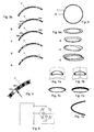
Fig. 1 zeigt eine Draufsicht der Ringuhr in der Ausführungsform einer Armbanduhr. -
Fig. 2 zeigt einen Querschnitt durch das umlaufende Band des Uhrenringes. -
Fig. 3a bis 3e zeigen Anzeigemöglichkeiten von Stunden, Minuten und Sekunden auf einem gemeinsamen Ring von LEDs. -
Fig. 4 zeigt die Anzeige eines Zeitwertes, der zwischen zwei LEDs liegt. -
Fig. 5 zeigt die Verwendung eines Musters von LEDs als Zeitmarkierung. -
Fig. 6a bis 6d zeigen Anordnungen von mehreren Zeitringen.Fig. 7a und 7d zeigen mögliche Variationen der Ringausformung aus der Ringfläche heraus. -
Fig. 8 zeigt einen Schaltplan zur Ansteuerung von vier LEDs. -
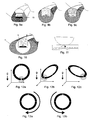
Fig. 9a bis 9c zeigen alternative Bauweisen des Uhrenringes. -
Fig. 10 zeigt einen Querschnitt durch das umlaufende Band des Uhrenringes mit einem weiteren umgebenden Material und der Ausformung der Vergußmasse mit optischem Linseneffekt. -
Fig. 11 zeigt den Vorgang einer Schalterauslösung durch Berührung der Zeitanzeige mit der Fingerkuppe. -
Fig. 12a bis 12c zeigen die Positionen eines Leuchtpunktes auf dem Uhrenring, die sich nach der Schwerkraft ausrichten. -
Fig. 13a und 13b zeigen die Drehrichtung eines über den Uhrenring streichenden Fingers zum Verstellen der Uhrzeit. -
Fig. 14 zeigt die Anordnung von Eingabeelementen und Stromversorgung der Armbanduhr im Armband. -
Fig. 15 zeigt die Anordnung von Ein- und Ausgabeelementen in der Schließe. -
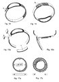
Fig. 16a zeigt die modulare Zerlegbarkeit der Uhrenarmbandes. -
Fig. 16b zeigt eine Schließendesign mit sicherem Verschluß bei gleichzeitig darin eingebauter und wasserdicht verschlossener Batterie. -
Fig. 17a und 17b zeigen zwei Ausführungen von Centerelementen, die in den Mittelteil der Ringuhr temporär eingefügt werden können. -
Fig. 18 zeigt die Anordnung von Step-up-Konverter und Elektronikmodulen im Uhrenarmband. -
Fig. 19a bis 19c zeigen Schaltungsweisen für Module des Uhrenarmbandes, die Strom- und/oder Datenleitungen umfassen. -
Fig. 20 zeigt die modulare Verkettung einzelner Elemente des Uhrenarmbandes, die zur Durchleitung elektrischen Stroms vorgesehen sind. -
Fig. 21 zeigt den Knickschutz für elektrische Leitungen im biegsamen Uhrenarmband. -
Fig. 22 zeigt ausschnittsweise die Anordnung von LEDs auf einer ringförmigen Platine. -
Fig. 23 zeigt die Ausführung der Ringuhr als Taschenuhr. -
Fig. 24 zeigt die Ausführung der Ringuhr als Fingerring. -
Fig. 25 zeigt die Ausführung der Ringuhr als Wanduhr. -
Fig. 26 zeigt eine Brille, um deren Gläser ein Uhrenring angeordnet ist. - Gemäß den
Fig. 1 und 2 liegen in der Nut 13 eines dünnen Stahlringes 1 eingebettet elektronische Platinen 2, auf welchen sich aneinandergereiht ein Vielfaches von 12, insbesondere von 60 vorzugsweise mehrfarbige Leuchtdioden (LEDs) 16 befinden, die Stunden, Minuten, Sekunden und weitere Informationen anzeigen können. Es werden hier auf einem einzigen Kreis von LEDs verschiedene Parameter angezeigt; die Unterscheidung erfolgt durch die Leuchtfarbe, die Helligkeit, die Anzahl der leuchtenden LEDs bzw. das grafische Leuchtmuster oder eine zeitliche Veränderung der vorstehenden Parameter (z.B. Blinken, Pulsieren, Funkeln,Fig. 3a bis 3e ). Die Breite des Ringes richtet sich also nur nach der technisch realisierbaren Dicke der Leuchtelemente und kann somit alle bisher bekannten Lösungen unterschreiten. - Die Leuchtfarben und Formen von Anzeigeparametern werden zweckmäßig so gewählt, daß Überlappungen nicht zum Verdecken von Parametern führen. So ist es beispielsweise vorteilhaft, die Stundenanzeige durch 2-4 hintereinanderliegende Punkte zu symbolisieren, welche nur mit halber Helligkeit leuchten, die Minuten dagegen mit einen einzigen Punkt, der mit voller Helligkeit leuchtet. Diese Anzeigesymbole können einander damit überlagern und dennoch einzeln erkannt werden. Möglich ist auch eine Unterscheidung der Parameter durch andere Leuchtfarben. Wenn man Punkteanzahl, Leuchtfarbe und Blinkrhythmus zur Codierung verwendet, können viele Parameter gleichzeitig auf dem selben Kreis dargestellt werden.
- Erfindungsgemäß wird die Stundenposition durch eine feine Skala, die vorzugsweise 60 mögliche Positionen aufweist, angegeben. So leuchtet bei 10:30 der Stundenpunkt nicht wie bei bekannten Uhren auf 10 oder 11, was zu Verwechslungen führen kann, sondern zwischen 10 und 11, analog zu einer Zeigeruhr.
- Darüber hinaus können Position zwischen zwei Leuchtpunkten derart angezeigt werden, daß sich beide benachbarten Punkte die Gesamthelligkeit eines einzelnen Punktes in einem bestimmten Verhältnis teilen, so daß derjenige Punkt heller leuchtet, welcher der exakten Position näher ist (Anzeigetechnik des Anti-Aliasing). Liegt die errechnete Position eines Punktes z.B. genau zwischen zwei LEDs, so werden diese LEDs beide mit halber Helligkeit angesteuert. Liegt die Position näher bei einer LED, so wird diese LED heller, die andere LED dunkler angesteuert, genau im Verhältnis des Abstandes der exakten Leuchtposition zu den beiden anzeigenden LEDs (
Fig. 4 ). - Damit bildet die hier vorliegende Lösung die theoretisch beliebig feine Unterteilung einer analogen Zeigeruhr nach. Auf diese Weise kann auch der Effekt eines sich stufenlos und stetig fortbewegenden Punktes (z.B. eines Sekundenpunktes) erreicht werden.
- Die Stunden- und Minuten-Anzeigepunkte leuchten ständig und können sich mit Hilfe eines Helligkeitssensors der Umgebungshelligkeit anpassen. Damit kann in dunkleren Umgebungen der Stromverbrauch der Uhr gesenkt werden.
- Sinkt die Umgebungshelligkeit unter einen bestimmten Wert, und können somit die aufgedruckten Zeitmarkierungen in der Dunkelheit nicht mehr abgelesen werden, werden bei den vollen Stunden Leuchtelemente aktiviert (vorzugsweise blau), welche die Zeitmarkierungen der vollen Stunden übernehmen. Zur genauen Orientierung werden dabei die 3-Uhr-, 6-Uhr-, 9-Uhr- und 12-Uhr-Positionen heller oder in anderer Farbe dargestellt, die 12-Uhr-Position dabei nochmals hervorgehoben, z.B. durch Aufleuchten dreier nebeneinander liegender Punkte.
- Zur Zeitanzeige ist eine LED-Anzahl von 60 vorzuziehen. Eine noch höhere Auflösung läßt sich durch eine LED-Anzahl erreichen, die bevorzugt ein ganzzahliges Vielfaches von 60 beträgt. Werden kleinere Ringdurchmesser benötigt, wird eine kleinere Anzahl von LEDs verwendet, bevorzugt aber ein ganzzahliges Vielfaches von 12. Durch die Technik des Anti-Aliasing kann auch durch eine LED-Anzahl, die nur ein ganzzahliges Vielfaches von 12 beträgt, ein stetiger Eindruck der Zeitanzeige erreicht werden. Zur Orientierung und besseren Abschätzung der genauen Uhrzeit ist es sinnvoll, auch 5-Minuten-Markierungen entlang des Ringes anzubringen.
- Die LEDs sind über die Leitungen, die in der ringförmigen Platine eingebettet sind, mit dem Prozessor 6 verbunden. Dieser besitzt Ausgänge, welche entweder hochohmig, low oder high geschaltet werden können. Anode und Kathode jeder LED sind derart mit diesen Ausgängen verbunden, daß sich die beiden Anschlüsse jeder LED in mindestens einem Ausgang unterscheiden. Anders ausgedrückt, ist die maximal steuerbare LED-Anzahl erreicht, wenn jeder Ausgang mit jedem beliebigem anderen Ausgang über zwei antiparallel geschaltete LEDS verbunden ist. Bei n Ausgängen kann man damit n·(n-1) LEDs steuern. (Beispiel: 4 Ausgänge, 12 LEDs,
Fig. 8 ). Bei 16 Ausgängen kann man 16·15 = 240 LEDs ansteuern und erreicht damit die für eine optimale vollfärbige Uhrenanzeige notwendige Mindestanzahl von 60·3 = 180 LEDs. - Wenn keine LED leuchtet, sind sämtliche Ausgänge hochohmig; wenn eine bestimmte LED leuchten soll, wird ihre Anode auf low geschaltet, die Kathode auf high. Da auf diese Weise nur jeweils eine einzige LED zur gleichen Zeit angesteuert werden kann, müssen, wenn mehrere LEDS leuchten sollen, diese sequentiell angesteuert werden, vorzugsweise mit einer Frequenz, die höher als die Grenzfrequenz des menschlichen Auges ist, damit kein Flackern wahrgenommen werden kann, also größer als 50 Hz, vorzugsweise 128 Hz.
- Die Anzeige der Zeit erfolgt, indem diejenigen Positionen, auf die bei einer Zeigeruhr die Zeiger zeigen würden, durch die LEDs optisch hervorgehoben werden, beispielsweise durch Aufleuchten eines Farbpunktes. Aber auch die Zeitmarkierungen selbst (z.B. die vollen Stunden) können durch die LEDs dargestellt werden (
Fig. 5 ) bzw. Weckzeiten, Stoppzeiten, Alarmzeiten usw. Damit diese verschiedenen Zeichen unterscheidbar sind, müssen sie sich in einer optischen Eigenschaft unterscheiden, z.B. Farbe, Helligkeit, grafisches Muster, Bewegungsmuster, zeitliche Veränderung. - Zum Unterscheiden von Stunden, Minuten und Sekunden sind prinzipiell beliebige Farbvarianten möglich, vorzugsweise werden Stunden durch einen oder mehrere rote Farbpunkte gekennzeichnet, Minuten durch einen grünen Punkt, Sekunden durch einen blauen Punkt, und die 12 Stundenmarkierungen durch einen blauen Punkt. Damit die Anzeige in heller Umgebung besser lesbar ist, können die Anzeigepunkte auch pulsieren bzw. zyklisch ihre Farbe wechseln (beides vorzugsweise mit ca. 1-4 Hz).
- Werden die 12 Stundenmarkierungen nicht fix am Uhrenring angebracht, sondern durch LEDs angezeigt, so kann die Winkelposition der gesamten Anzeige durch den Prozessor beliebig gedreht werden. Bewegt man z.B. die Uhr, wird ihre Lage im Raum mit Hilfe des integrierten Lagesensors festgestellt; der Prozessor dreht dann die gesamte Anzeige immer so, daß sich die 12-Uhr-Position immer am gravimetrisch höchsten Punkt der Uhr befindet.
- Die Anzeigepunkte können von dem Prozessor in ihrer Helligkeit verändert werden. Dies wird vorzugsweise durch Pulsweitenmodulation erreicht. Damit können sowohl weiche Helligkeitsübergänge (Anti-Aliasing) als auch eine automatische Anpassung an die Umgebungshelligkeit erreicht werden. Dabei geschieht die Messung der Umgebungshelligkeit entweder durch Messung des reverse Bias-Strom der Anzeige-LEDs selbst (
Fig. 11 ) oder durch einen eigenen Helligkeitssensor. - Der in der Uhr integrierte Lage- bzw. Beschleunigungssensor kann feststellen, wenn die Uhr bewegt oder in einer bestimmten Position gehalten wird und damit bei Bedarf die Helligkeit der Anzeige nochmals erhöhen oder zu verringern (um Strom zu sparen). Hängt beispielsweise die Hand nach unten, kann angenommen werden, daß die Uhr nicht abgelesen wird, und die Anzeige wird abgedunkelt. Liegt die Uhr annähernd waagrecht, kann angenommen werden, daß die Zeit abgelesen wird und die Anzeige wird heller gestellt. Bewegt man die Uhr (absichtlich) heftig, kann die Anzeige besonders hell gestellt werden.
- Mehrere solcher Anzeigeringe können in verschiedenen räumlichen Positionen angeordnet werden, um z.B. gleichzeitig andere Zeitzonen oder weitere Parameter anzuzeigen, auch überlappend oder in mehreren Ebenen (
Fig. 6a bis 6d ). - Die Anzeigeringe müssen nicht notwendigerweise eine Kreisform aufweisen, sie können beliebige Formen, z.B. ovale, drei-, vier- und mehreckige, annehmen. Die Fläche, in welcher die Ringe liegen, muß nicht notwendigerweise eben sein. Sie kann auch gekrümmt sein oder Knicke aufweisen (
Fig. 7a und 7b ). Die Anzeigeringe selbst können ebenfalls geknickt (Fig. 7c ) oder kegelförmig gekrümmt sein (Abb. 7d ). Die LEDs können auch auf einer oder mehreren offenen Kurven liegen. - Die Energiequelle 14 ist aus Platzgründen nicht im Uhrenring, sondern außerhalb, vorzugsweise im Armband 12 oder in der Schließe 29, mit welchen der Uhrenring elektrisch verbunden ist, angeordnet. Im Vergleich zu Anordnungen im Uhrengehäuse ermöglicht die externe Energieversorgung durch das höhere Volumen wesentlich längere Zeitperioden zwischen Akku-Nachladungen und Batteriewechseln bzw. eine hellere Anzeige.
- Vorzugsweise sollen im Armband integrierte flexible Akkumulatoren 35, z.B. Lithium-Polymer-Schnelladeakkus, verwendet werden. Das Aufladen kann über die Seitenkanten des Armbandes erfolgen: eine Uhrbandseite bildet den Pluspol, die andere den Minuspol - dies verhindert ein zufälliges Kurzschließen der Kontakte durch Berührung metallischer Gegenstände.
- Das Ladegerät für die integrierten Akkumulatoren kann netzbetrieben sein, ist bevorzugt aber netzunabhängig, entweder batteriebetrieben bzw. selbst aufladbar. Damit kann die Uhr auch unterwegs geladen werden.
- Eine Batterie 30 kann auch in der Schließe 29 der Uhr untergebracht werden. Dazu dient ein Schließendesign, welches die Batterie wasserdicht einschließt und trotzdem einen sicheren Verschluß des Uhrbandes sicherstellt (
Fig. 16b ). - Der Uhrenring wird mit einer konstanten Spannung (vorzugsweise 5 V) versorgt, welche von den Stromversorgungselementen bereitgestellt wird. Dies sichert ein gleichmäßiges Leuchten der LEDs der Ringuhr über die gesamte Lebensdauer der Batterie bzw. des Akkumulators. Die Uhr weist einen kleinen Kondensator 7 auf, der parallel zur Spannungsversorgung liegt, daher ständig geladen wird und bei Batterie- oder Modulwechsel für eine bestimmte Zeit die Stromversorgung der Uhr sicherstellt. Sinkt die Spannung an der Uhr unter einen bestimmten Wert, wird dies vom Prozessor erkannt, er geht in einen Ruhemodus und schaltet alle nicht direkt zur Zeitmeldung benötigten Stromverbraucher ab (LEDs, A/D Wandler etc.).
- Das Uhrbandmodul 28 mit integriertem Akku 35 besitzt einen eigenen Elektronikteil, welcher die vom Akku gelieferte Spannung (typisch 3,7 V) mit einem Step-up Konverter 36a auf 5 V konvertiert (
Fig. 18 ). Liefert der Akku eine höhere Spannung (z.B. durch Hintereinanderschaltung von zwei Akkumulatoren), wird die Spannung auf 5 V mit einem Step-down Konverter 36b gesenkt. - Erfolgt die Stromversorgung durch das Schließenmodul, so enthält dieses ebenfalls einen eigenen Elektronikteil, der beliebige Eingangsspannungen zwischen 0,9 und 4 V auf konstante 5 V konvertiert.
- Der Mikroprozessor, der alle Funktionen der Uhr inklusive der Steuerung der LEDs übernimmt, befindet sich mit dem Uhrenquarz und anderen elektronischen Bauteilen in Ausbuchtungen 4 und 5 am oberen und unteren Ende des Uhrenringes (
Fig. 1 ). An diesen Ausbuchtungen wird auch das Uhrenband angebracht. Alle zum Betrieb der Uhr notwendigen Bauteile können aber auch direkt auf der Unterseite der ringförmigen Platine liegen, welche auch die Anzeige-LEDs trägt, oder überhaupt außerhalb des Uhrenringes liegen, und mit diesem über flexible Leiterbahnen 37 verbunden sein. - Der Mikroprozessor läuft vorzugsweise mit einer Taktfrequenz über 1 MHz, um die Anzeige flackerfrei zu bedienen und weitere Programme ausführen zu können. Diese Frequenz muß nicht quarzstabilisiert werden. Die Zeitbasis für die Uhr dagegen wird von einem Uhrenquarz gegeben, der an einem Eingang des Prozessors sein Signal einspeist.
- Der Uhrenring verfügt aus Platzgründen auch über mechanischen Eingabeelemente, wie z.B. eine Krone, nicht mehr. Die Bedienung der Uhr erfolgt entweder über externe Eingabeelemente 27 im Armband (
Fig. 14 ) oder in der Schließe (Fig. 15 ), bevorzugt aber über berührungssensitive Sensoren am Uhrenring, d.h. über die LEDs der Zeitanzeige selbst, die als Reflexlichtschranken 25 und 26 verwendet werden, indem, wie bereits bekannt, ihr "reverse bias"-Strom gemessen wird (Fig. 11 ). Alternativ ist die Eingabe auch über die Technik des "Simulierten Massepunktes" bzw. durch Klopfen an das Gehäuse möglich. - Im Armband oder in der Schließe 29 können Eingabeelemente 27 (Taster, Sensorelemente) untergebracht werden, welche elektrisch mit dem Uhrenring verbunden sind.
- Das Einstellen und die Bedienung der Uhr kann durch die LEDs der Anzeige selbst erfolgen: über Messung des Leckstromes bei reverse biased LEDs kann festgestellt werden, ob sich über der LED eine Fingerkuppe 24 befindet: in diesem Fall wirkt der Finger wie ein Reflektor für das Licht einer danebenliegenden LED und beleuchtet die Sense-LED 26, deren Widerstand daraufhin sinkt, was, wie bereits bekannt, der Mikroprozessor erkennen und auswerten kann. Stellen für den Gebrauch einer Sense-LED sind z.B. die 3-, 6-, 9- oder 12-er Position, denn an diesen Stellen muß eine LED leuchten, damit die danebenliegende LED als Sense-LED fungieren kann. Um zufällige Fehlbedienungen zu vermeiden, müssen bei Beginn einer Eingabe z.B. zwei am Ring gegenüberliegende LEDs (z.B. "3" und "9") gleichzeitig berührt oder ein anderes Schaltelement (z.B. in der Schließe oder im Uhrband) bedient werden.
- Im Fall der Bedienung der Uhr über Sensoren 22 am Uhrenring ist das Gehäuse der Uhr elektrisch leitend ausgeführt. Innerhalb dieses Gehäuses sind Sensorbereiche ausgeführt, die vom Gehäuse elektrisch isoliert sind. Vorzugsweise liegen diese Sensorbereiche auf dem inneren Ring, und können dort wieder unterteilt werden und den Raum zwischen zwei Zeitmarkierungen ausfüllen. Die Sensorbereiche sind ebenso wie das Gehäuse mit dem Prozessor verbunden. Legt man den Finger auf einen Sensorbereich und überbrückt den Spalt zwischen Gehäuse und Sensor, so kann ein geringer Strom zwischen Sensorelement und Gehäuse über sie Fingerkuppe fließen, was vom Prozessor erkannt werden kann und einen Schaltvorgang auslöst. Es reicht aber auch, nur ein Sensorelement allein anzutippen: in diesem Fall fließt ein geringer Strom von der Unterseite der Uhr über den Körper und die Fingerspitze in den Sensor, was wiederum einen Schaltvorgang auslöst.
- Eine kreisförmige Anordnung der Sensorelemente 10 am Uhrenring ermöglicht es, durch kreisförmiges Streichen des Fingers im oder gegen den Uhrzeigersinn über die Anzeige z.B. die Zeit einzustellen, wie wenn man physikalische Zeiger mit der Hand vor- oder rückdrehen wollte (
Fig. 13a und 13b ). - Eine weitere alternative Eingabemöglichkeit nützt einen integrierten Lagesensor-Chip. Dabei wird ein Leuchtpunkt vom Uhrenprozessor wie ein massebehaftetes Element simuliert. Schüttelt man die Uhr, wird der Leuchtpunkt im Anzeigering ebenfalls hin- und hergeschüttelt. Kippt man die Uhr, bewegt sich der Leuchtpunkt an die tiefste Stelle des Ringes (
Fig. 12a bis 12c ). Ist nun z.B. jeder vollen Stunde eine bestimmte Aktion zugeordnet (z.B. Aktion "Enter" = 12 Uhr oder Aktion "set" = 6 Uhr), so wird genau diejenige Aktion ausgeführt, an der sich der Leuchtpunkt befindet, wenn ein Eingabeelement gedrückt wird. Damit kann die Uhr mit ein- und demselben Eingabeelement viele unterschiedliche Aktionen durchführen. - Um Energie für die Versorgung der LEDs zu sparen, kann ein Eingabevorgang in die Uhr mehrstufig ausgeführt werden: beispielsweise kann durch Berühren eines Sensorelementes oder des Uhrengehäuses das eigentliche Display-Sensing eingeleitet werden, welches dann die LEDs zum Sensen aktiviert, oder auch durch eine Schüttelbewegung der Uhr ausgelöst werden.
- Die Sensorelemente des Uhrenringes können auch durch Widerstandsmessung detektieren, ob sich die Uhr unter Wasser befindet und in diesem Fall über die Sensorelemente nach außen geführte Stromversorgung abschalten, um Kurzschlüsse zu vermeiden.
- Da der integrierte Lage- und Beschleunigungssensor auch kurze Stöße, wie sie durch Klopfen an den Uhrenring entstehen, detektieren kann, ist es möglich, durch verschiedene zeitlich verschiedene Klopfsignale bestimmte Aktionen auszulösen. Um Fehlbedienung zu vermeiden, kann das von der Bedienung einer Computermaus bekannte Doppel-Klicken verwendet werden, um anzuzeigen, daß nachfolgend eine Bedienung vorgenommen werden soll. Ein nochmaliges Doppel-Klicken bringt die Uhr wieder vom zuvor gewählten Modus in den Normalzustand zurück.
- Im Uhrenring bzw. in den Erweiterungsmodulen können sich weitere Sensoren 9 befinden, die beispielsweise Magnetfelder (Kompaß), Luftdruck, Temperatur, Feuchtigkeit usw. messen können, Daten speichern können (Diktiergerät), Musik aufnehmen und abspielen können (MP3), Fernbedienungsfunktionen ausführen können, und über Infrarot oder Funksignale (Bluetooth) mit anderen elektronischen Geräten kommunizieren können.
- Um die Bruchsicherheit des Uhrenringes zu gewährleisten, ist die LED-Anzeige vorzugsweise in die Nut einer Stahl-Tragstruktur eingelegt und dort wasserdicht eingegossen und versiegelt (
Fig. 2 ). Die Trägerstruktur kann mit anderen Materialien, wie etwa Kunststoffe oder Farben, beschichtet oder überhaupt von anderen Materialien 21, wie etwa Holz, Stein, Kunststoff oder Metalle, umgeben sein (Fig. 10 ). - Die Trägerstruktur kann vorteilhaft aus mehreren Teilen 1 und 15 bestehen (
Fig. 2 ,9a ). Diese weisen zusammengesetzt einen Querschnitt mit einer Nut auf, welche die elektronische Platinen 2 aufnimmt. Die detaillierte Querteilung der Trägerstruktur wird nach den Gesichtspunkten einer einfachen Herstellung vorgenommen in dem Sinne, daß nach dem Einlegen der elektronischen Platine 2 ein letzter Schlußteil die Platine mechanisch im Ring fixiert. Die Trägerstruktur kann auch aus einem einzigen Stück gefertigt werden, beispielsweise durch selektive Laserschmelztechnik. In diesem Fall wird die elektronische Platine 2 in die Nut des Uhrenringes 1 eingelegt und dort durch Klebepunkte fixiert; das anschließende Vergießen der Nut fixiert die Platine mechanisch im Ring. - Der Querschnitt kann verschiedene Formen annehmen (z.B. rechteckig, kreisförmig, elliptisch). Die einzelnen Teile können zusammengeschraubt, gesteckt, geklebt, gefügt werden.
- Die ringförmigen Platinen, welche in die Nut eingelegt sind, bestehen vorzugsweise aus Multilayer-Material. Sie können in den Ausbuchtungen der Uhr erweitert sein und dort auf ihrer Unterseite Prozessor, Quarz, Kondensatoren, Sensoren etc. aufweisen. Auf der Oberseite der Platinen angebracht sind lichtemittierende Bauteile, vorzugsweise LEDs, vorzugsweise mehrfärbige LEDs, vorzugsweise RGB-LEDs (aber auch OLEDs, Quantenpunkt-LEDs etc). Werden UV-emittierende LEDs eingesetzt, werden darüberliegende Kunststoffe (Quantenpunkt-Nanomaterialien) angebracht (in der Vergußmasse eingebettet), welche das UV-Licht in sichtbares Licht wandeln.
- Die LEDs sind entweder diskret auf die Platinen aufgelötet oder auch aufgeklebt und direkt auf die Platine gebondet. In einer bevorzugten Anordnung (
Fig. 22 ) werden RGB-SMD-LEDs 41 verwendet, welche eine gemeinsame Kathode oder eine gemeinsame Anode aufweisen. Eine spezielle Entflechtung der ringförmigen Multilayerplatine stellt sicher, daß die LEDs so eng wie möglich aneinander gereiht werden können, ohne daß beim Lötverfahren Kurzschlüsse zwischen den Anschlüssen 42 der LEDS entstehen. - Über der ringförmigen Platine können sich weitere ringförmige Elemente befinden, beispielsweise dünne Metallmasken 19, die z.B. mit Zeitsymbolen oder Zeitmarkierungen oder anderen Mustern bedruckt oder gefräst sein können (
Fig. 2 ), oder Kunststofflinsen, welche das Licht der LEDs bündeln oder andere optische Elemente (z.B. Prismen, Fresnellinsen), oder Farbfilter, welche z.B. zur Kontrasterhöhung nur den Farbanteil des Spektrums durchlassen, welchen die jeweils darunterliegende LED aussendet, oder Gitter. - All diese Elemente werden, nachdem sie übereinandergelegt und fixiert wurden, mit einem durchsichtigen Werkstoff vergossen, vorzugsweise ein Polymerkunststoff, der unter kurzwelligem Licht härtet. Damit liegen zwischen LEDs und Außenseite der Uhr keine Luftschichten, an deren Grenzflächen sonst das von außerhalb der Uhr kommende Licht reflektiert wird und damit den für eine optimale Ablesbarkeit notwendigen Kontrast zwischen LED-Licht und Umgebung verringert.
- Die Innenseite 17 der Nut 13 im Metallring ist nach unten verbreitert und/oder mit Rillen versehen und/oder auf andere Weise aufgerauht, so daß der sich Polymerkunststoff stabil verankern kann.
- Die Innenseite der (konischen) Nut kann Zeitmarkierungen oder Zeitsymbole 18 aufweisen oder mit anderen Mustern gefräst oder bedruckt sein.
- Der Verguß-Kunststoff kann gefärbt werden, vorzugsweise zur Erhöhung des Kontrastes dunkel eingefärbt oder halbdurchlässig verspiegelt sein, UV-aktive Substanzen aufweisen (oder Quantenpunkt-Nanomaterialien), andere optische Materialien enthalten (Prismen, Pigmente, Spiegel).
- Die Vergußmasse kann nach dem Härten geschliffen und poliert werden und/oder mit Zeitmarkierungen versehen werden. Wird die Oberfläche gewölbt geschliffen, so kann sie das Licht der darunterliegenden LEDs bündeln. Die transparente Vergußmasse kann damit durch ihre Wölbung auf der Oberseite die Funktion einer optischen (Zylinder-)Linse übernehmen und die Leuchtpunkt optisch vergrößern bzw. ihr Licht zum Betrachter hin bündeln (
Fig. 10 ). - Durch das vollständige Vergießen der Multilayerplatine mit LEDs, Prozessor und weiteren elektronischen Bauteilen wird die ringförmige Anordnung wasserdicht.
- Eine andere Variante ist das paßgenaue Einkleben eines konischen Glasringes 23. Dieser Glasring stellt eine torusförmige Linse dar, welche das Licht der darunterliegenden LED bündeln kann. Die Innenseite des Glasringes kann mit Zeitmarkierungen graviert sein oder bedruckt sein, ebenso können die konischen Glasflächen mit Zeitmarkierungen graviert oder bedruckt sein.
- Bevorzugt werden alle elektronischen Bauteile der Uhr auf der Unterseite der Multilayerplatine angebracht. Für eine preiswertere Realisierung weist der Uhrenring oben und unten eine Ausbuchtung 4 und 5 auf, welche sowohl weitere elektronische Bauteile aufnehmen kann wie Prozessor 6, Kondensator 7, Sensoren 8, als auch einen Teil eines Gelenkes darstellt, welches mit einem oberen und unteren ersten Glied eines Uhrarmbandes 12 verbunden ist (
Fig. 1 ). - Die Konstruktion des Gelenkes kann durch einen integrierten Anschlag die mögliche maximale Drehbewegung auf einen bestimmten Winkel beschränken (
Fig. 20 ), damit der maximale Biegeradius innengeführter flexibler Leiterbahnen 37 und/oder Leitungen nicht überschritten wird. - Im Innenraum des Uhrenringes können Centerelemente 31 und 33 plaziert werden, die rasch wechselbar sind und neben rein optischen Designfunktionen auch eigene Elektronik und technische Funktionen enthalten können, z.B. Stoppuhr, Kompaß, Thermometer, Hyrometer, Barometer, MP3-Player, Kamera, Bluetooth. Die Centerelemente können zylinderförmig sein (
Fig. 17a ) oder ebenfalls Ringform aufweisen (Fig. 17b ). Um ein elegantes Design zu erreichen, soll die Uhr keine Einkerbungen oder Ausstülpungen zur Befestigung der Centerelemente aufweisen. Beispielsweise weisen die Centerelemente an ihrem Rand mehrere integrierte Neodym-Magnete 32 auf, die sie damit magnetisch im Stahlring der Ringuhr halten und sie automatisch zentrieren (Fig. 16a ), oder weisen einen Federmechanismus auf, oder sind mit elastischem Material verkleidet. - Die Centerelemente können bei integrierter Elektronik eine eigene Batterie aufweisen. Die Stromversorgung kann aber auch über die Ringuhr erfolgen, vorzugsweise über die gleichen Federkontakte, welche das Centerelement in der Ringuhr zentrieren. Auch ein eventueller Datenaustausch mit der Ringuhr erfolgt über diese Federkontakte.
- Da das Armband bzw. die Schließe mit dem Uhrenring elektrisch verbunden sind, können sie ihrerseits Sensoren und Ein- oder Ausgabeelemente enthalten (
Fig. 14, 15 ), beispielsweise eine Datumsanzeige. - Zur Erweiterung der Uhrenfunktionen können Uhrenring, Schließe und Uhrenband als Modulsystem ausgeführt werden. Dazu führen zu und durch die Einzelelemente (Uhrenring, Uhrenband, Schließe, Module) gleichzeitig Strom- und Datenleitungen (
Fig. 18, 19a bis 19c ). In jedem dieser Module können damit eigene Ein- und Ausgabeelemente, Sensoren, Prozessoren 34 enthalten sein. - All diese Einzelelemente können vom Benutzer getauscht werden (
Fig. 16a ). Damit läßt sich die Uhr mit neuen Modulen 28 nachrüsten, z.B. mit leistungsfähigeren Akkumulatoren oder neuen Sensoren. - Damit die Module 28 wasserdicht und flexibel miteinander verbunden sind und vom Benutzer selbst ausgetauscht werden können, sind Kontakte 38 und 39 und Gelenke 40 getrennt: ein wasserdichtes Gelenk führt die Kabel zu einer Kontaktleiste, die geöffnet werden kann. Damit können Module beliebig getauscht werden, das Armband verlängert/verkürzt werden (
Fig. 20 ). - Eine weitere Möglichkeit (bevorzugt) zur Stromübertragung zwischen den Modulen ist die Verwendung von flexiblen Leiterbahnen 37, die zwischen zwei Schutzschichten eingebettet liegen. Damit diese Leiterbahnen nicht geknickt werden können, können die Gelenke durch einen konstruktionsbedingten Anschlag nur in einem eingeschränkten Winkel bewegt werden (
Fig. 21 ). - Um eine Bruchsicherheit des Uhrenringes zu erzielen, kann die Trägerstruktur auch aus biegsamem und elastischem Material gefertigt werden. Die Struktur muß in diesem Fall auch mit transparentem, elastischem Material vergossen werden. Die Platinen müssen dann aus flexiblem Material gefertigt werden.
- Der Uhrenring kann auch in anderen Ausführungsformen neben der Armbanduhr Anwendung finden, beispielsweise als Taschenuhr 43 (
Fig. 23 ), oder als Fingerring 44 (Abb. 24 ). Der Uhrenring kann auch um andere Gegenstände herum gebaut sein, beispielsweise am Rand der Innenseite von Brillengläsern, so daß der Brillenträger bequem die Zeit ablesen kann, diese Information für Außenstehende aber nicht sichtbar ist. Obwohl der Brillenträger die Leuchtpunkte aufgrund ihrer extremen Nähe nicht fokussieren kann, kann er dennoch die Position der unscharfen Punkte erkennen und somit die Zeit erfassen (Abb. 25 ). - Es sind aber auch wesentlich größere Ausführungen des Uhrenringes denkbar, z.B. als Wand- oder Standuhr 45 (
Abb. 25 ). Da ein erfindungsgemäßer Uhrenring sehr dünn und schlank ist, können im Gegensatz zu herkömmlichen Uhren Designs mit wesentlich größeren Durchmessern realisiert werden, die sich trotzdem in ihre Umgebung integrieren.
Claims (21)
- Uhr, die elektronisch gesteuert ist und deren Gehäuse und Anzeigefeld als Ring (1) ausgebildet sind, wobei die Uhranzeigen durch auf dem Ring (1) umlaufend schaltbare Leuchtmittel gebildet sind, und wobei zumindest eine ringförmige Reihe von mindestens 60 Leuchtdioden (LEDs) (16) vorgesehen ist, wobei durch den Leuchtzustand einzelner LEDs (16) mindestens die Zeitparameter "Stunde", "Minute" und zusätzlich der Zeitparameter "Sekunde" eingeordnet sind, um indiziert zu werden, und eine als ringförmiges Anzeigefeld dienende elektronische Platine (2) an einer der Ringstirnseiten angeordnet ist, dadurch gekennzeichnet, daß die Leuchtdioden (16) untereinander eine gleiche Größe aufweisen, wobei alle Leuchtdioden eingeordnet sind, um den Zeitparameter "Stunde" anzeigen zu können, sowie, daß sich die Anzeigen von Stunden, Minuten und Sekunden durch das Leuchtmuster und/oder die Leuchtfarbe und/oder die Helligkeit und/oder die Leuchtverteilung auf mehrere benachbarte LEDs voneinander unterscheiden.
- Uhr nach Anspruch 1, dadurch gekennzeichnet, daß das Uhrengehäuse (1, 15) aus mindestens einem ringförmigen Stück, vorzugsweise aus Stahl besteht und vorzugsweise kreisförmig ist, wobei das Uhrengehäuse (1, 15) eine Nut (13) aufweist, in der die eingelegte und fixierte Anzeigeelektronik mit einem transparenten Material (20) verschlossen wird.
- Uhr nach Anspruch 1 oder 2, gekennzeichnet dadurch, daß das als Ring ausgebildete Uhrengehäuse (1, 15) an einer oder mehreren Stellen offen ist.
- Uhr nach einem der Ansprüche 1 bis 3, gekennzeichnet dadurch, daß ein Helligkeitssensor zur Anpassung der Helligkeit der Anzeige an das Umgebungslicht im Uhrengehäuse (1, 15) angeordnet ist, wobei der Leuchtkontrast unabhängig von der Umgebungshelligkeit ist.
- Uhr nach einem der Ansprüche 1 bis 4, gekennzeichnet dadurch, daß über den Leuchtdioden (16) kontrastverstärkendes, dunkles, transparentes Material oder eine halbdurchlässige spiegelnde Schicht angeordnet ist.
- Uhr nach einem der Ansprüche 1 bis 5, gekennzeichnet dadurch, daß die Leuchtdioden (16) durch mehrfarbige SMD-LEDs gebildet sind.
- Uhr nach einem der Ansprüche 1 bis 6, gekennzeichnet dadurch, daß im Uhrengehäuse (1, 15) eine elektronische Vorrichtung zur Realisation von Anzeigepositionen zwischen zwei Anzeigepunkten durch Antialiasing angeordnet ist.
- Uhr nach einem der Ansprüche 1 bis 7, gekennzeichnet dadurch, daß das transparente Material (20), mit dem eine elektronische Platine (2) mit den Leuchtelementen verschlossen ist, eine transparente Kunststoffmasse ist, mit der die elektronische Platine (2) wasserdicht vergießbar ist.
- Uhr nach einem der Ansprüche 1 bis 8, gekennzeichnet dadurch, daß in der transparenten Kunststoffmasse über den LEDs Farbfilter eingebettet liegen, welche nur das Lichtspektrum der jeweiligen darunterliegenden LED durchlassen.
- Uhr nach einem der Ansprüche 1 bis 9, gekennzeichnet dadurch, daß in der transparenten Kunststoffmasse optische Elemente, wie Spiegel, Prismen, Diffusoren, Linsen etc., eingebettet sind.
- Uhr nach einem der Ansprüche 1 bis 10, gekennzeichnet dadurch, daß die transparenten Kunststoffmasse auf der Oberseite des Uhrenringes gewölbt ausgeprägt ist, um das Licht der darunterliegenden LEDs zu bündeln.
- Uhr nach einem der Ansprüche 1 bis 11, gekennzeichnet dadurch, daß über den LEDs Metall- oder Kunststoffmasken (19) liegen, welche bedruckbar und mit Zeitmarkierungen versehbar sind.
- Uhr nach einem der Ansprüche 1 bis 12, gekennzeichnet dadurch, daß die Seitenwände (17) der Nut (13) des Uhrengehäuses (1, 15), die die elektronische Platine (2) mit den LEDs aufnimmt, mit Markierungen (18) versehen sind.
- Uhr nach einem der Ansprüche 1 bis 13, dadurch gekennzeichnet, daß ein elektronischer Lagesensor zur Ermittlung der Richtung der Gravitation im Uhrengehäuse (1, 15) untergebracht ist.
- Uhr nach einem der Ansprüche 1 bis 14, gekennzeichnet dadurch, daß die Batterie als aufladbarer flexibler Akkumulator (35) im Armband (12) integriert ist.
- Uhr nach Anspruch 15, gekennzeichnet dadurch, daß das Uhrengehäuse (1, 15) elektrisch mit dem Armband (12) verbunden ist.
- Uhr nach Anspruch 15, gekennzeichnet dadurch, daß das Armband (12) elektrisch mit einer Schließe (29) verbunden ist.
- Uhr nach Anspruch 15, gekennzeichnet dadurch, daß im Armband (12) und/oder in der Schließe (29) weitere Ein- und Ausgabeelemente (27) enthalten sind.
- Uhr nach einem der Ansprüche 1 bis 18, gekennzeichnet dadurch, daß die ringförmige Anzeige auf opto-elektronische Weise als berührungssensitives Feld ausgebildet ist, über das die Einstellung der angezeigten Information erfolgt.
- Uhr nach einem der Ansprüche 1 bis 19, dadurch gekennzeichnet, daß ein Lage-/Beschleunigungssensor mit einem Prozessor (23) verbunden ist und die Eingabe der gewünschten Information mittels Ausrichtung der Uhr im Gravitationsfeld erfolgt.
- Uhr nach einem der Ansprüche 1 bis 20, dadurch gekennzeichnet, daß ein Lage-/Beschleunigungssensor mit einem Prozessor (23) verbunden ist und die Eingabe der gewünschten Information mittels Klopfen an das Uhrengehäuse erfolgt.
Applications Claiming Priority (2)
| Application Number | Priority Date | Filing Date | Title |
|---|---|---|---|
| AT0083507A AT505245B1 (de) | 2007-05-25 | 2007-05-25 | Elektronisch gesteuerte uhr |
| PCT/AT2008/000176 WO2008144786A1 (de) | 2007-05-25 | 2008-05-20 | Elektronisch gesteuerte uhr |
Publications (2)
| Publication Number | Publication Date |
|---|---|
| EP2149074A1 EP2149074A1 (de) | 2010-02-03 |
| EP2149074B1 true EP2149074B1 (de) | 2011-11-02 |
Family
ID=39684363
Family Applications (1)
| Application Number | Title | Priority Date | Filing Date |
|---|---|---|---|
| EP08747898A Not-in-force EP2149074B1 (de) | 2007-05-25 | 2008-05-20 | Elektronisch gesteuerte uhr |
Country Status (6)
| Country | Link |
|---|---|
| US (1) | US8588032B2 (de) |
| EP (1) | EP2149074B1 (de) |
| JP (1) | JP2010528269A (de) |
| AT (2) | AT505245B1 (de) |
| CA (1) | CA2711341A1 (de) |
| WO (1) | WO2008144786A1 (de) |
Families Citing this family (54)
| Publication number | Priority date | Publication date | Assignee | Title |
|---|---|---|---|---|
| AT12968U1 (de) * | 2008-11-25 | 2013-03-15 | Christian Dipl Ing Lackner | Gerät zur darstellung von datum, uhrzeit, alarmen sowie weiteren informationen |
| CH703619A2 (de) * | 2010-08-20 | 2012-02-29 | Markus Ofner | Elektronische uhr mit optoelektronischen anzeigeelementen. |
| BE1019839A3 (nl) * | 2011-01-14 | 2013-01-08 | Diamond Trading Nv | Uurwerk. |
| DE102011085306A1 (de) * | 2011-10-27 | 2013-05-02 | Zumtobel Lighting Gmbh | Leuchte mit Zeitanzeige |
| CN202889407U (zh) * | 2012-03-15 | 2013-04-17 | 中兴通讯股份有限公司 | 一种便携式终端 |
| CN105473021B (zh) | 2013-03-15 | 2018-01-19 | 智能专利有限责任公司 | 可穿戴设备及相关系统 |
| KR102138503B1 (ko) | 2013-04-09 | 2020-07-28 | 엘지전자 주식회사 | 스마트 워치 |
| KR101486251B1 (ko) * | 2013-09-04 | 2015-01-28 | 주식회사 필룩스 | 시계 |
| JP6329833B2 (ja) * | 2013-10-04 | 2018-05-23 | パナソニック インテレクチュアル プロパティ コーポレーション オブ アメリカPanasonic Intellectual Property Corporation of America | ウェアラブル端末及びウェアラブル端末の制御方法 |
| WO2015079270A1 (en) * | 2013-11-26 | 2015-06-04 | Somos Sándor | Ring-shaped clockwork and procedure for using the clockwork |
| US8861314B1 (en) * | 2013-11-27 | 2014-10-14 | Luminosity Industries LLC | System, apparatus, and method for displaying the time of day |
| EP4071581B1 (de) | 2013-11-29 | 2025-10-08 | Ouraring Inc. | Am körper tragbare berechnungsvorrichtung |
| US20150261189A1 (en) * | 2014-03-12 | 2015-09-17 | Google Inc. | Wrist-Worn Device with Removable Head Unit |
| US9152129B2 (en) | 2014-06-25 | 2015-10-06 | Dilshan Thilina Modaragamage | Electronic watch clasp systems and methods |
| JP6565139B2 (ja) * | 2014-06-27 | 2019-08-28 | カシオ計算機株式会社 | 電子時計 |
| DE202014005491U1 (de) * | 2014-07-07 | 2014-11-13 | Christian Stroetmann | Mobiles Computersystem, das eine Vorrichtung zur optischen, mehrfarbigen Signalisierung von veränderlichen Informationen, eine Stromversorgung und ein Computergehäuse besitzt |
| EP4160376A1 (de) | 2014-08-02 | 2023-04-05 | Apple Inc. | Verfahren zum bearbeiten einer benutzerschnittstelle eines zifferblatts bei einer uhr mit einem berührungsempfindlichen display |
| US10452253B2 (en) | 2014-08-15 | 2019-10-22 | Apple Inc. | Weather user interface |
| KR102218913B1 (ko) * | 2014-09-04 | 2021-02-23 | 엘지전자 주식회사 | 스마트 팔찌 |
| WO2016144385A1 (en) | 2015-03-08 | 2016-09-15 | Apple Inc. | Sharing user-configurable graphical constructs |
| KR101639338B1 (ko) * | 2015-04-30 | 2016-07-13 | 성균관대학교산학협력단 | 태핑 인식을 통한 입력 인터페이스를 제공하는 방법 및 이를 위한 스마트 시계 장치 |
| US10304347B2 (en) | 2015-08-20 | 2019-05-28 | Apple Inc. | Exercised-based watch face and complications |
| DE212015000276U1 (de) * | 2015-09-18 | 2017-07-21 | Kabushiki Kaisha Yaskawa Denki | Zustandsanzeigevorrichtung für die Industriemaschine und Leistungswandlungsvorrichtung |
| US20170199498A1 (en) * | 2016-01-07 | 2017-07-13 | Silverplus, Inc | Led notification watch |
| US12175065B2 (en) | 2016-06-10 | 2024-12-24 | Apple Inc. | Context-specific user interfaces for relocating one or more complications in a watch or clock interface |
| US11307434B2 (en) * | 2016-09-01 | 2022-04-19 | 3D Live, Inc. | Stereoscopic display apparatus employing light emitting diodes with polarizing film/lens materials |
| KR20230038303A (ko) | 2016-09-23 | 2023-03-17 | 애플 인크. | 워치 극장 모드 |
| CN106527740A (zh) * | 2016-12-19 | 2017-03-22 | 珠海格力电器股份有限公司 | 穿戴式智能设备及与之配合的终端 |
| DK179412B1 (en) | 2017-05-12 | 2018-06-06 | Apple Inc | Context-Specific User Interfaces |
| DK179555B1 (en) | 2017-05-16 | 2019-02-13 | Apple Inc. | USER INTERFACE FOR A FLASHLIGHT MODE ON AN ELECTRONIC DEVICE |
| US10642228B1 (en) * | 2017-09-15 | 2020-05-05 | Apple Inc. | LED-backed housing split of a portable electronic device |
| WO2019060815A1 (en) | 2017-09-25 | 2019-03-28 | Alexander Wellen | NUMERIC DIGITAL SHAPE PIECE PIECE FOR TACTILE DETERMINING THE TIME SPENT |
| CN107657679B (zh) * | 2017-10-25 | 2023-12-15 | 大连理工大学 | 游泳练习60秒计时器 |
| US11327650B2 (en) | 2018-05-07 | 2022-05-10 | Apple Inc. | User interfaces having a collection of complications |
| CN108762034A (zh) * | 2018-07-27 | 2018-11-06 | 村哲实业(漳州)有限公司 | 一种改进型发光时钟 |
| US11507027B2 (en) | 2019-02-25 | 2022-11-22 | Daniel Grupp | Illuminated time-passage indicator |
| EP3712719B1 (de) * | 2019-03-20 | 2021-11-10 | Renata AG | Armbanduhr mit in der schliesse integrierter batterie |
| US11960701B2 (en) | 2019-05-06 | 2024-04-16 | Apple Inc. | Using an illustration to show the passing of time |
| US11131967B2 (en) | 2019-05-06 | 2021-09-28 | Apple Inc. | Clock faces for an electronic device |
| JP6921338B2 (ja) | 2019-05-06 | 2021-08-18 | アップル インコーポレイテッドApple Inc. | 電子デバイスの制限された動作 |
| US10878782B1 (en) | 2019-09-09 | 2020-12-29 | Apple Inc. | Techniques for managing display usage |
| CN112947883B (zh) * | 2019-09-09 | 2022-07-12 | 苹果公司 | 用于管理显示器使用的技术 |
| US11372659B2 (en) | 2020-05-11 | 2022-06-28 | Apple Inc. | User interfaces for managing user interface sharing |
| DK202070624A1 (en) | 2020-05-11 | 2022-01-04 | Apple Inc | User interfaces related to time |
| CN115552375A (zh) | 2020-05-11 | 2022-12-30 | 苹果公司 | 用于管理用户界面共享的用户界面 |
| US20210389732A1 (en) * | 2020-06-15 | 2021-12-16 | John L. Schooley | Digital Clock with Free Form Path |
| US11694590B2 (en) | 2020-12-21 | 2023-07-04 | Apple Inc. | Dynamic user interface with time indicator |
| US11720239B2 (en) | 2021-01-07 | 2023-08-08 | Apple Inc. | Techniques for user interfaces related to an event |
| US12182373B2 (en) | 2021-04-27 | 2024-12-31 | Apple Inc. | Techniques for managing display usage |
| US11921992B2 (en) | 2021-05-14 | 2024-03-05 | Apple Inc. | User interfaces related to time |
| EP4102307A1 (de) * | 2021-06-08 | 2022-12-14 | The Swatch Group Research and Development Ltd | Uhr mit lokalisierter beleuchtung |
| US12493267B2 (en) | 2022-01-24 | 2025-12-09 | Apple Inc. | User interfaces for indicating time |
| TWI814477B (zh) * | 2022-07-08 | 2023-09-01 | 友達光電股份有限公司 | 顯示裝置 |
| WO2025148746A1 (en) * | 2024-01-11 | 2025-07-17 | One Balance Advanced Technology (Hong Kong) Limited | Timepiece |
Family Cites Families (46)
| Publication number | Priority date | Publication date | Assignee | Title |
|---|---|---|---|---|
| US1096682A (en) * | 1910-04-18 | 1914-05-12 | Edward E Clement | Electrically-illuminated clock. |
| DE2600487A1 (de) * | 1975-02-13 | 1976-08-26 | Timex Corp | Elektronische uhr |
| US3509715A (en) * | 1966-02-01 | 1970-05-05 | Gen Time Corp | Electronic clocks |
| US3633355A (en) * | 1969-07-05 | 1972-01-11 | Sakata Watch Co Ltd | Watch crystal and hands with reflective mirror dial |
| US3757511A (en) * | 1971-05-17 | 1973-09-11 | Motorola Inc | Light emitting diode display for electronic timepiece |
| US3968639A (en) * | 1971-06-03 | 1976-07-13 | American Cyanamid Company | Electrochromic information displays |
| US3955354A (en) * | 1974-02-11 | 1976-05-11 | Jack S. Kilby | Display for electronic clocks and watches |
| US3955356A (en) * | 1974-03-19 | 1976-05-11 | Texas Instruments Incorporated | Watch having positioned controlled display actuator |
| US3922847A (en) * | 1974-05-06 | 1975-12-02 | Texas Instruments Inc | VLED solid state watch |
| US3958409A (en) * | 1974-09-12 | 1976-05-25 | Solomon Manber | Watch display |
| US4007583A (en) | 1975-05-22 | 1977-02-15 | Rca Corporation | Electronic timepiece |
| DE2551542A1 (de) * | 1975-11-17 | 1977-05-26 | Joachim Reich | Elektronische uhr |
| FR2376450A1 (fr) * | 1976-12-29 | 1978-07-28 | Cetehor | Procede et appareil d'affichage de l'heure par diodes electroluminescentes |
| US4525077A (en) * | 1982-01-05 | 1985-06-25 | Ketner Eugene N | Timepiece having central opening |
| US4473304A (en) * | 1982-01-05 | 1984-09-25 | Ketner Eugene N | Toroidal time piece |
| JPS611193U (ja) * | 1984-06-08 | 1986-01-07 | 博康 塩川 | 腕時計 |
| GB2162663B (en) | 1984-08-02 | 1987-10-14 | Hui David | Timepiece |
| JPS6166179A (ja) * | 1984-09-01 | 1986-04-04 | ソーラートロン,インコーポレイティド | 時計 |
| JPS6249334U (de) * | 1985-09-17 | 1987-03-26 | ||
| JPS62278482A (ja) * | 1986-05-28 | 1987-12-03 | Seiko Epson Corp | 指針表示式時計 |
| US4702615A (en) * | 1986-12-24 | 1987-10-27 | Karel Havel | Analog display timepiece |
| GB8730080D0 (en) | 1987-03-02 | 1988-02-03 | Saito Goro | Method of displaying elapse of time in analog manner of digital timepiece |
| JPH0171693U (de) * | 1987-11-04 | 1989-05-12 | ||
| IT8805167A0 (it) | 1988-05-25 | 1988-05-25 | Zoli Paolo Gardone V T Brescia | Bracciale luminoso con un orologio, oppure una foto, oppure un amuleto, o un'emblema, illuminabili tramite led, batterie e circuiti contenuti nello stesso. |
| JPH0710319Y2 (ja) * | 1988-08-17 | 1995-03-08 | シチズン時計株式会社 | 腕時計構造 |
| US4920524A (en) * | 1988-08-22 | 1990-04-24 | Kotob Mohammed N | Multimode digital timepiece |
| IL96983A0 (en) * | 1991-01-21 | 1992-03-29 | Mordechai Teicher | Orientation-sensitive display system |
| GB9500668D0 (en) * | 1995-01-13 | 1995-03-08 | Radley Smith Philip J | Bracelet |
| US5694376A (en) * | 1995-09-27 | 1997-12-02 | Niobrara Research And Development Corporation | Method and enhanced clock for displaying time |
| DE19845579A1 (de) * | 1998-10-02 | 2000-04-13 | Mannesmann Vdo Ag | Anzeigevorrichtung |
| JP2000199791A (ja) * | 1998-12-30 | 2000-07-18 | Shigeo Chikui | 指輪時計 |
| JP2000278391A (ja) * | 1999-03-26 | 2000-10-06 | Nec Saitama Ltd | 背面手書き入力機能を有する携帯電話機 |
| NL1012053C2 (nl) | 1999-05-12 | 2000-11-14 | Petrus Johannes Maria Post | Inrichting voor het weergeven van tijd. |
| KR100695073B1 (ko) * | 1999-11-11 | 2007-03-14 | 더 스워치 그룹 매니지먼트 서비시스 아게 | 가요성을 가진 손목밴드내에 구성된 인쇄회로를 포함하는 손목시계 |
| TW507120B (en) | 2000-05-16 | 2002-10-21 | Gen Scanning Inc | Method and subsystem for generating a trajectory to be followed by a motor-driven stage when processing microstructures at a laser-processing site |
| GB2384063A (en) | 2001-11-30 | 2003-07-16 | Michael Zinaburg | Revolving watches |
| US6683822B2 (en) | 2001-12-04 | 2004-01-27 | Chin-Shuei Cheng | Time display device |
| JP3090923U (ja) * | 2002-06-10 | 2003-01-10 | 清水 鄭 | 時計の表示板 |
| US6690623B1 (en) * | 2002-11-08 | 2004-02-10 | Arnold K. Maano | Multi-functional time indicating device with a multi-colored fiber optic display |
| GB2409295A (en) | 2003-12-19 | 2005-06-22 | Bruce Lankford | Watch in the form of a band |
| US20050276164A1 (en) * | 2004-06-12 | 2005-12-15 | Scott Amron | Watch adapted to rotate a displayed image so as to appear in a substantially constant upright orientation |
| US20060062089A1 (en) * | 2004-09-17 | 2006-03-23 | Lizzi Ronald S | Timepiece with LCD schedule function |
| WO2006033317A1 (ja) * | 2004-09-24 | 2006-03-30 | Ricoh Elemex Corporation | アナログ腕時計 |
| TWM275438U (en) * | 2005-05-17 | 2005-09-11 | Super Nova Optoelectronics Cor | Timer display device having light generating module with circular arrangment |
| JP2007040776A (ja) * | 2005-08-02 | 2007-02-15 | Hitomi Matsuda | 発光ダイオードを用いた時計 |
| JP2007107949A (ja) * | 2005-10-12 | 2007-04-26 | Citizen Electronics Co Ltd | 照光式時計 |
-
2007
- 2007-05-25 AT AT0083507A patent/AT505245B1/de not_active IP Right Cessation
-
2008
- 2008-05-20 EP EP08747898A patent/EP2149074B1/de not_active Not-in-force
- 2008-05-20 JP JP2010508665A patent/JP2010528269A/ja active Pending
- 2008-05-20 CA CA2711341A patent/CA2711341A1/en not_active Abandoned
- 2008-05-20 WO PCT/AT2008/000176 patent/WO2008144786A1/de not_active Ceased
- 2008-05-20 AT AT08747898T patent/ATE532115T1/de active
- 2008-05-25 US US12/602,007 patent/US8588032B2/en not_active Expired - Fee Related
Also Published As
| Publication number | Publication date |
|---|---|
| WO2008144786A1 (de) | 2008-12-04 |
| ATE532115T1 (de) | 2011-11-15 |
| US20110182151A1 (en) | 2011-07-28 |
| EP2149074A1 (de) | 2010-02-03 |
| CA2711341A1 (en) | 2008-12-04 |
| JP2010528269A (ja) | 2010-08-19 |
| US8588032B2 (en) | 2013-11-19 |
| AT505245B1 (de) | 2011-02-15 |
| AT505245A1 (de) | 2008-12-15 |
Similar Documents
| Publication | Publication Date | Title |
|---|---|---|
| AT505245B1 (de) | Elektronisch gesteuerte uhr | |
| US4920524A (en) | Multimode digital timepiece | |
| US4041692A (en) | Electronic clock having time indicating light display | |
| US6084828A (en) | Timepiece and chronometer with overlapping, separately driven analog and digital displays | |
| DE69502546T2 (de) | Schalteinrichtung und mit der Schalteinrichtung ausgestattete elektronische Geräte | |
| US6683822B2 (en) | Time display device | |
| US20060092770A1 (en) | Information displays and methods associated therewith | |
| DE2113350A1 (de) | Elektronischer Zeitmesser,insbesondere Armbanduhr | |
| US4752919A (en) | Clock with digital hour station and line of discrete, binary minute substations | |
| EP1455250A2 (de) | Elektronische Zeitmessvorrichtung | |
| US10048652B1 (en) | Analog timepiece with steps illustrating arrangement | |
| KR20160073009A (ko) | 시각 장애인용 시계 | |
| CN202758171U (zh) | Led手表 | |
| US4030285A (en) | Electronic hour glass clock | |
| DE2742242A1 (de) | Digitale zeiger-zifferblatt-uhr mit analog-anzeigesymbolik | |
| EP3735617B1 (de) | Individuell und professionell gestaltbarer zeitmesser | |
| US20060062089A1 (en) | Timepiece with LCD schedule function | |
| US9891588B1 (en) | Linear clock | |
| WO1994004967A1 (de) | Uhr | |
| US20120147714A1 (en) | Geometrical-figure time display | |
| EP0786119A2 (de) | Schachuhr | |
| RU44185U1 (ru) | Часы с заменяемыми электронными изображениями | |
| CN204422982U (zh) | 一种多功能电子表 | |
| KR20010052140A (ko) | 각각 구동되는 아날로그 및 디지털 디스플레이가 겹쳐진시계 및 정밀시계 | |
| CN210721041U (zh) | 一种闹钟 |
Legal Events
| Date | Code | Title | Description |
|---|---|---|---|
| PUAI | Public reference made under article 153(3) epc to a published international application that has entered the european phase |
Free format text: ORIGINAL CODE: 0009012 |
|
| 17P | Request for examination filed |
Effective date: 20091118 |
|
| AK | Designated contracting states |
Kind code of ref document: A1 Designated state(s): AT BE BG CH CY CZ DE DK EE ES FI FR GB GR HR HU IE IS IT LI LT LU LV MC MT NL NO PL PT RO SE SI SK TR |
|
| AX | Request for extension of the european patent |
Extension state: AL BA MK RS |
|
| 17Q | First examination report despatched |
Effective date: 20100802 |
|
| DAX | Request for extension of the european patent (deleted) | ||
| RAP1 | Party data changed (applicant data changed or rights of an application transferred) |
Owner name: GEYER, MICHAEL Owner name: KRIEGER, SYLVIA Owner name: KRIEGER, MARTIN |
|
| RIN1 | Information on inventor provided before grant (corrected) |
Inventor name: KRIEGER FRANZ |
|
| GRAP | Despatch of communication of intention to grant a patent |
Free format text: ORIGINAL CODE: EPIDOSNIGR1 |
|
| GRAS | Grant fee paid |
Free format text: ORIGINAL CODE: EPIDOSNIGR3 |
|
| GRAA | (expected) grant |
Free format text: ORIGINAL CODE: 0009210 |
|
| AK | Designated contracting states |
Kind code of ref document: B1 Designated state(s): AT BE BG CH CY CZ DE DK EE ES FI FR GB GR HR HU IE IS IT LI LT LU LV MC MT NL NO PL PT RO SE SI SK TR |
|
| REG | Reference to a national code |
Ref country code: GB Ref legal event code: FG4D Free format text: NOT ENGLISH |
|
| REG | Reference to a national code |
Ref country code: CH Ref legal event code: EP |
|
| REG | Reference to a national code |
Ref country code: IE Ref legal event code: FG4D |
|
| REG | Reference to a national code |
Ref country code: DE Ref legal event code: R096 Ref document number: 502008005465 Country of ref document: DE Effective date: 20120202 |
|
| REG | Reference to a national code |
Ref country code: NL Ref legal event code: T3 |
|
| REG | Reference to a national code |
Ref country code: CH Ref legal event code: NV Representative=s name: ISLER & PEDRAZZINI AG |
|
| LTIE | Lt: invalidation of european patent or patent extension |
Effective date: 20111102 |
|
| PG25 | Lapsed in a contracting state [announced via postgrant information from national office to epo] |
Ref country code: NO Free format text: LAPSE BECAUSE OF FAILURE TO SUBMIT A TRANSLATION OF THE DESCRIPTION OR TO PAY THE FEE WITHIN THE PRESCRIBED TIME-LIMIT Effective date: 20120202 Ref country code: LT Free format text: LAPSE BECAUSE OF FAILURE TO SUBMIT A TRANSLATION OF THE DESCRIPTION OR TO PAY THE FEE WITHIN THE PRESCRIBED TIME-LIMIT Effective date: 20111102 Ref country code: IS Free format text: LAPSE BECAUSE OF FAILURE TO SUBMIT A TRANSLATION OF THE DESCRIPTION OR TO PAY THE FEE WITHIN THE PRESCRIBED TIME-LIMIT Effective date: 20120302 |
|
| PG25 | Lapsed in a contracting state [announced via postgrant information from national office to epo] |
Ref country code: GR Free format text: LAPSE BECAUSE OF FAILURE TO SUBMIT A TRANSLATION OF THE DESCRIPTION OR TO PAY THE FEE WITHIN THE PRESCRIBED TIME-LIMIT Effective date: 20120203 Ref country code: PT Free format text: LAPSE BECAUSE OF FAILURE TO SUBMIT A TRANSLATION OF THE DESCRIPTION OR TO PAY THE FEE WITHIN THE PRESCRIBED TIME-LIMIT Effective date: 20120302 Ref country code: PL Free format text: LAPSE BECAUSE OF FAILURE TO SUBMIT A TRANSLATION OF THE DESCRIPTION OR TO PAY THE FEE WITHIN THE PRESCRIBED TIME-LIMIT Effective date: 20111102 Ref country code: SI Free format text: LAPSE BECAUSE OF FAILURE TO SUBMIT A TRANSLATION OF THE DESCRIPTION OR TO PAY THE FEE WITHIN THE PRESCRIBED TIME-LIMIT Effective date: 20111102 Ref country code: SE Free format text: LAPSE BECAUSE OF FAILURE TO SUBMIT A TRANSLATION OF THE DESCRIPTION OR TO PAY THE FEE WITHIN THE PRESCRIBED TIME-LIMIT Effective date: 20111102 Ref country code: LV Free format text: LAPSE BECAUSE OF FAILURE TO SUBMIT A TRANSLATION OF THE DESCRIPTION OR TO PAY THE FEE WITHIN THE PRESCRIBED TIME-LIMIT Effective date: 20111102 Ref country code: HR Free format text: LAPSE BECAUSE OF FAILURE TO SUBMIT A TRANSLATION OF THE DESCRIPTION OR TO PAY THE FEE WITHIN THE PRESCRIBED TIME-LIMIT Effective date: 20111102 |
|
| REG | Reference to a national code |
Ref country code: IE Ref legal event code: FD4D |
|
| PG25 | Lapsed in a contracting state [announced via postgrant information from national office to epo] |
Ref country code: CY Free format text: LAPSE BECAUSE OF FAILURE TO SUBMIT A TRANSLATION OF THE DESCRIPTION OR TO PAY THE FEE WITHIN THE PRESCRIBED TIME-LIMIT Effective date: 20111102 |
|
| PG25 | Lapsed in a contracting state [announced via postgrant information from national office to epo] |
Ref country code: DK Free format text: LAPSE BECAUSE OF FAILURE TO SUBMIT A TRANSLATION OF THE DESCRIPTION OR TO PAY THE FEE WITHIN THE PRESCRIBED TIME-LIMIT Effective date: 20111102 Ref country code: SK Free format text: LAPSE BECAUSE OF FAILURE TO SUBMIT A TRANSLATION OF THE DESCRIPTION OR TO PAY THE FEE WITHIN THE PRESCRIBED TIME-LIMIT Effective date: 20111102 Ref country code: BG Free format text: LAPSE BECAUSE OF FAILURE TO SUBMIT A TRANSLATION OF THE DESCRIPTION OR TO PAY THE FEE WITHIN THE PRESCRIBED TIME-LIMIT Effective date: 20120202 Ref country code: EE Free format text: LAPSE BECAUSE OF FAILURE TO SUBMIT A TRANSLATION OF THE DESCRIPTION OR TO PAY THE FEE WITHIN THE PRESCRIBED TIME-LIMIT Effective date: 20111102 Ref country code: CZ Free format text: LAPSE BECAUSE OF FAILURE TO SUBMIT A TRANSLATION OF THE DESCRIPTION OR TO PAY THE FEE WITHIN THE PRESCRIBED TIME-LIMIT Effective date: 20111102 Ref country code: IE Free format text: LAPSE BECAUSE OF FAILURE TO SUBMIT A TRANSLATION OF THE DESCRIPTION OR TO PAY THE FEE WITHIN THE PRESCRIBED TIME-LIMIT Effective date: 20111102 |
|
| PG25 | Lapsed in a contracting state [announced via postgrant information from national office to epo] |
Ref country code: RO Free format text: LAPSE BECAUSE OF FAILURE TO SUBMIT A TRANSLATION OF THE DESCRIPTION OR TO PAY THE FEE WITHIN THE PRESCRIBED TIME-LIMIT Effective date: 20111102 |
|
| PLBE | No opposition filed within time limit |
Free format text: ORIGINAL CODE: 0009261 |
|
| STAA | Information on the status of an ep patent application or granted ep patent |
Free format text: STATUS: NO OPPOSITION FILED WITHIN TIME LIMIT |
|
| 26N | No opposition filed |
Effective date: 20120803 |
|
| REG | Reference to a national code |
Ref country code: DE Ref legal event code: R097 Ref document number: 502008005465 Country of ref document: DE Effective date: 20120803 |
|
| BERE | Be: lapsed |
Owner name: GEYER, MICHAEL Effective date: 20120531 Owner name: KRIEGER, SYLVIA Effective date: 20120531 Owner name: KRIEGER, MARTIN Effective date: 20120531 |
|
| PG25 | Lapsed in a contracting state [announced via postgrant information from national office to epo] |
Ref country code: MC Free format text: LAPSE BECAUSE OF NON-PAYMENT OF DUE FEES Effective date: 20120531 |
|
| PG25 | Lapsed in a contracting state [announced via postgrant information from national office to epo] |
Ref country code: BE Free format text: LAPSE BECAUSE OF NON-PAYMENT OF DUE FEES Effective date: 20120531 |
|
| PG25 | Lapsed in a contracting state [announced via postgrant information from national office to epo] |
Ref country code: FI Free format text: LAPSE BECAUSE OF FAILURE TO SUBMIT A TRANSLATION OF THE DESCRIPTION OR TO PAY THE FEE WITHIN THE PRESCRIBED TIME-LIMIT Effective date: 20111102 |
|
| PG25 | Lapsed in a contracting state [announced via postgrant information from national office to epo] |
Ref country code: MT Free format text: LAPSE BECAUSE OF FAILURE TO SUBMIT A TRANSLATION OF THE DESCRIPTION OR TO PAY THE FEE WITHIN THE PRESCRIBED TIME-LIMIT Effective date: 20111102 |
|
| PG25 | Lapsed in a contracting state [announced via postgrant information from national office to epo] |
Ref country code: ES Free format text: LAPSE BECAUSE OF FAILURE TO SUBMIT A TRANSLATION OF THE DESCRIPTION OR TO PAY THE FEE WITHIN THE PRESCRIBED TIME-LIMIT Effective date: 20120213 |
|
| PG25 | Lapsed in a contracting state [announced via postgrant information from national office to epo] |
Ref country code: TR Free format text: LAPSE BECAUSE OF FAILURE TO SUBMIT A TRANSLATION OF THE DESCRIPTION OR TO PAY THE FEE WITHIN THE PRESCRIBED TIME-LIMIT Effective date: 20111102 |
|
| PG25 | Lapsed in a contracting state [announced via postgrant information from national office to epo] |
Ref country code: LU Free format text: LAPSE BECAUSE OF NON-PAYMENT OF DUE FEES Effective date: 20120520 |
|
| PG25 | Lapsed in a contracting state [announced via postgrant information from national office to epo] |
Ref country code: HU Free format text: LAPSE BECAUSE OF FAILURE TO SUBMIT A TRANSLATION OF THE DESCRIPTION OR TO PAY THE FEE WITHIN THE PRESCRIBED TIME-LIMIT Effective date: 20080520 |
|
| REG | Reference to a national code |
Ref country code: FR Ref legal event code: PLFP Year of fee payment: 8 |
|
| REG | Reference to a national code |
Ref country code: FR Ref legal event code: PLFP Year of fee payment: 9 |
|
| REG | Reference to a national code |
Ref country code: FR Ref legal event code: PLFP Year of fee payment: 10 |
|
| PGFP | Annual fee paid to national office [announced via postgrant information from national office to epo] |
Ref country code: GB Payment date: 20170614 Year of fee payment: 10 Ref country code: FR Payment date: 20170628 Year of fee payment: 10 Ref country code: CH Payment date: 20170511 Year of fee payment: 10 |
|
| PGFP | Annual fee paid to national office [announced via postgrant information from national office to epo] |
Ref country code: NL Payment date: 20170630 Year of fee payment: 10 |
|
| PGFP | Annual fee paid to national office [announced via postgrant information from national office to epo] |
Ref country code: IT Payment date: 20170918 Year of fee payment: 10 |
|
| REG | Reference to a national code |
Ref country code: CH Ref legal event code: PL |
|
| REG | Reference to a national code |
Ref country code: NL Ref legal event code: MM Effective date: 20180601 |
|
| GBPC | Gb: european patent ceased through non-payment of renewal fee |
Effective date: 20180520 |
|
| PG25 | Lapsed in a contracting state [announced via postgrant information from national office to epo] |
Ref country code: CH Free format text: LAPSE BECAUSE OF NON-PAYMENT OF DUE FEES Effective date: 20180531 Ref country code: LI Free format text: LAPSE BECAUSE OF NON-PAYMENT OF DUE FEES Effective date: 20180531 |
|
| PG25 | Lapsed in a contracting state [announced via postgrant information from national office to epo] |
Ref country code: FR Free format text: LAPSE BECAUSE OF NON-PAYMENT OF DUE FEES Effective date: 20180531 Ref country code: IT Free format text: LAPSE BECAUSE OF NON-PAYMENT OF DUE FEES Effective date: 20180520 Ref country code: GB Free format text: LAPSE BECAUSE OF NON-PAYMENT OF DUE FEES Effective date: 20180520 Ref country code: NL Free format text: LAPSE BECAUSE OF NON-PAYMENT OF DUE FEES Effective date: 20180601 |
|
| PGFP | Annual fee paid to national office [announced via postgrant information from national office to epo] |
Ref country code: AT Payment date: 20190531 Year of fee payment: 12 |
|
| PGFP | Annual fee paid to national office [announced via postgrant information from national office to epo] |
Ref country code: DE Payment date: 20200602 Year of fee payment: 13 |
|
| REG | Reference to a national code |
Ref country code: AT Ref legal event code: MM01 Ref document number: 532115 Country of ref document: AT Kind code of ref document: T Effective date: 20200520 |
|
| PG25 | Lapsed in a contracting state [announced via postgrant information from national office to epo] |
Ref country code: AT Free format text: LAPSE BECAUSE OF NON-PAYMENT OF DUE FEES Effective date: 20200520 |
|
| REG | Reference to a national code |
Ref country code: DE Ref legal event code: R119 Ref document number: 502008005465 Country of ref document: DE |
|
| PG25 | Lapsed in a contracting state [announced via postgrant information from national office to epo] |
Ref country code: DE Free format text: LAPSE BECAUSE OF NON-PAYMENT OF DUE FEES Effective date: 20211201 |