EP2149171B3 - Trägervorrichtung für eine elektrochemische funktionseinrichtung, brennstoffzellemodul und verfahren zur herstellung einer trägervorrichtung - Google Patents
Trägervorrichtung für eine elektrochemische funktionseinrichtung, brennstoffzellemodul und verfahren zur herstellung einer trägervorrichtung Download PDFInfo
- Publication number
- EP2149171B3 EP2149171B3 EP08750135.9A EP08750135A EP2149171B3 EP 2149171 B3 EP2149171 B3 EP 2149171B3 EP 08750135 A EP08750135 A EP 08750135A EP 2149171 B3 EP2149171 B3 EP 2149171B3
- Authority
- EP
- European Patent Office
- Prior art keywords
- carrier device
- fuel cell
- frame unit
- accordance
- housing
- Prior art date
- Legal status (The legal status is an assumption and is not a legal conclusion. Google has not performed a legal analysis and makes no representation as to the accuracy of the status listed.)
- Active
Links
Images


Classifications
-
- H—ELECTRICITY
- H01—ELECTRIC ELEMENTS
- H01M—PROCESSES OR MEANS, e.g. BATTERIES, FOR THE DIRECT CONVERSION OF CHEMICAL ENERGY INTO ELECTRICAL ENERGY
- H01M8/00—Fuel cells; Manufacture thereof
- H01M8/02—Details
- H01M8/0202—Collectors; Separators, e.g. bipolar separators; Interconnectors
- H01M8/0247—Collectors; Separators, e.g. bipolar separators; Interconnectors characterised by the form
-
- H—ELECTRICITY
- H01—ELECTRIC ELEMENTS
- H01M—PROCESSES OR MEANS, e.g. BATTERIES, FOR THE DIRECT CONVERSION OF CHEMICAL ENERGY INTO ELECTRICAL ENERGY
- H01M8/00—Fuel cells; Manufacture thereof
- H01M8/02—Details
-
- H—ELECTRICITY
- H01—ELECTRIC ELEMENTS
- H01M—PROCESSES OR MEANS, e.g. BATTERIES, FOR THE DIRECT CONVERSION OF CHEMICAL ENERGY INTO ELECTRICAL ENERGY
- H01M8/00—Fuel cells; Manufacture thereof
- H01M8/02—Details
- H01M8/0202—Collectors; Separators, e.g. bipolar separators; Interconnectors
- H01M8/0204—Non-porous and characterised by the material
- H01M8/0206—Metals or alloys
- H01M8/0208—Alloys
- H01M8/021—Alloys based on iron
-
- H—ELECTRICITY
- H01—ELECTRIC ELEMENTS
- H01M—PROCESSES OR MEANS, e.g. BATTERIES, FOR THE DIRECT CONVERSION OF CHEMICAL ENERGY INTO ELECTRICAL ENERGY
- H01M8/00—Fuel cells; Manufacture thereof
- H01M8/02—Details
- H01M8/0271—Sealing or supporting means around electrodes, matrices or membranes
- H01M8/0273—Sealing or supporting means around electrodes, matrices or membranes with sealing or supporting means in the form of a frame
-
- Y—GENERAL TAGGING OF NEW TECHNOLOGICAL DEVELOPMENTS; GENERAL TAGGING OF CROSS-SECTIONAL TECHNOLOGIES SPANNING OVER SEVERAL SECTIONS OF THE IPC; TECHNICAL SUBJECTS COVERED BY FORMER USPC CROSS-REFERENCE ART COLLECTIONS [XRACs] AND DIGESTS
- Y02—TECHNOLOGIES OR APPLICATIONS FOR MITIGATION OR ADAPTATION AGAINST CLIMATE CHANGE
- Y02E—REDUCTION OF GREENHOUSE GAS [GHG] EMISSIONS, RELATED TO ENERGY GENERATION, TRANSMISSION OR DISTRIBUTION
- Y02E60/00—Enabling technologies; Technologies with a potential or indirect contribution to GHG emissions mitigation
- Y02E60/30—Hydrogen technology
- Y02E60/50—Fuel cells
-
- Y—GENERAL TAGGING OF NEW TECHNOLOGICAL DEVELOPMENTS; GENERAL TAGGING OF CROSS-SECTIONAL TECHNOLOGIES SPANNING OVER SEVERAL SECTIONS OF THE IPC; TECHNICAL SUBJECTS COVERED BY FORMER USPC CROSS-REFERENCE ART COLLECTIONS [XRACs] AND DIGESTS
- Y02—TECHNOLOGIES OR APPLICATIONS FOR MITIGATION OR ADAPTATION AGAINST CLIMATE CHANGE
- Y02P—CLIMATE CHANGE MITIGATION TECHNOLOGIES IN THE PRODUCTION OR PROCESSING OF GOODS
- Y02P70/00—Climate change mitigation technologies in the production process for final industrial or consumer products
- Y02P70/50—Manufacturing or production processes characterised by the final manufactured product
-
- Y—GENERAL TAGGING OF NEW TECHNOLOGICAL DEVELOPMENTS; GENERAL TAGGING OF CROSS-SECTIONAL TECHNOLOGIES SPANNING OVER SEVERAL SECTIONS OF THE IPC; TECHNICAL SUBJECTS COVERED BY FORMER USPC CROSS-REFERENCE ART COLLECTIONS [XRACs] AND DIGESTS
- Y10—TECHNICAL SUBJECTS COVERED BY FORMER USPC
- Y10T—TECHNICAL SUBJECTS COVERED BY FORMER US CLASSIFICATION
- Y10T29/00—Metal working
- Y10T29/49—Method of mechanical manufacture
- Y10T29/49002—Electrical device making
- Y10T29/49108—Electric battery cell making
Definitions
- the invention relates to a carrier device for an electrochemical functional device of a high-temperature fuel cell.
- the invention relates to a fuel cell module which comprises an electrochemical functional device.
- the invention relates to a method for producing a carrier device for an electrochemical functional device.
- a fuel cell module which has a fuel cell, which is provided at its anode and its cathode in each case with a current collector.
- the anode is attached to its current collector by means of a solder.
- U1 is a fuel cell unit comprising a cathode-electrolyte-anode unit and at least one contact element for electrically conductive contacting of the cathode-electrolyte-anode unit known.
- the at least one contact element comprises a plate provided with a plurality of openings.
- a carrier for an electrochemical functional unit of a high-temperature fuel cell which has a porosity for the supply of reactants and / or discharge of reaction products.
- a fuel cell stack which comprises a plurality of fuel cells, which are connected by connecting elements electrically and mechanically.
- the connecting elements are made of metal or a metal alloy and each connecting element has at least one electrode space and a porous wall. The porous wall of the connecting element separates the electrode space from an adjacent anode.
- fuel cells of the type SOFC which comprises a substrate made of a ferritic steel, which comprises a porous region and a non-porous region, the latter defining the porous region.
- a ferritic steel bipolar plate is positioned over a surface of the porous region of the substrate and is connected in sealing contact with the non-porous region of the substrate about the porous region.
- a first electrode layer is disposed on the other surface of the porous region of the substrate.
- An electrolyte layer is disposed on the first electrode layer and a second electrode layer is disposed over the electrolyte layer.
- a SOFC type fuel cell comprising a steel substrate having a porous support and a non-porous frame, the frame accommodating the porous support or a number of porous supports.
- the invention has for its object to provide a support device of the type mentioned, which can be produced in a simple manner and has advantageous properties.
- the carrier device comprises a frame device of an electrically conductive material and at least one window region made of an electrically conductive material, which is integrally formed on the frame device and is integrally arranged on the frame device, wherein the at least one window region a porous material and is permeable to gas through the porosity and wherein the frame means in the solid material is made by powder metallurgy, and different starting materials are used for the production of the frame means and the window area, wherein the starting materials comprise metal powder and binder and the binder part in the starting material for the window area is higher than in the starting material for the frame device.
- the carrier device is electrically conductive via the frame device and the at least one window region, so that it can be used, for example, as a bipolar plate or as an interconnector.
- an anode can be electrically contacted via the carrier device.
- the carrier device can serve as a carrier for an anode, wherein reaction gas can be carried out via the at least one porous window region of the anode.
- the support device with the frame device and the integral at least one window region can be produced in a simple manner by powder metallurgical methods. It is an integral production possible. As a result, the number of manufacturing steps and thus in turn the production cost can be kept low.
- gas-impermeable frame means and the at least one gas-permeable window area can be the electrical functional device selectively provide reaction gas such as fuel gas or oxidizer, which can also achieve a high density of a gas space in a simple manner.
- the frame material which is impermeable to gas in the solid material can be used as a supply device for reaction gas in a gas space by forming corresponding channels on the frame device. Accordingly, the frame device can also be used as a discharge device for reaction products.
- frame elements of the frame device laterally surround the at least one window area.
- the gas-permeable window region can be sealed laterally over the frame device.
- the at least one window area is in one piece arranged on the frame device. As a result, no cohesive, form-fitting or similar connection between the at least one window region and the frame device is necessary.
- the at least one window region and the frame device are made of the same material. As a result, no jumps in the coefficient of thermal expansion, in the distribution of stress, in the proportions of alloy, etc. arise between the at least one window region and the frame device at the transition.
- the carrier device is produced by powder metallurgy. This makes it possible to achieve a uniform (homogeneous) material distribution. This, in turn, the oxidation resistance of the support device is very high, because - are avoided, for example, compared to embossed carrier devices - "oxidation weak spots" due to uneven alloy distribution. Furthermore, the carrier device can be manufactured with high flatness, so that it can be easily positioned in a housing. In turn, this makes it possible to use the carrier device in a simple manner for the formation of fuel cell stacks of a plurality of fuel cells.
- the carrier device comprises one or more support feet.
- the support device can be supported on a base such as a housing.
- a gas space can be formed, via which reaction gas can be fed through the electrochemical functional device through the at least one window region.
- one or more support feet are arranged on the frame device.
- the corresponding mechanical stability can be achieved.
- a simple connectivity to the pad for example by soldering
- the one or more support feet are integrally formed on the frame means.
- the support feet are arranged and designed such that a gas space can be formed below the at least one window region.
- An underside of a support leg is then spaced from an underside of the at least one window area.
- the carrier device is designed as a bipolar plate or is designed as an interconnector. It can then simultaneously be the carrier of an electrochemical functional device and provide electrical contact.
- an electrical contact device is arranged on the frame device, via which the frame device can be supported on a housing.
- the electrical contact device can be an integral part of the frame device and, for example, integrally formed on this. It is also possible for a separate electrical contact device, for example in the form of a network, to be fixed to the frame device, for example via soldering.
- At least one electrochemical functional layer is favorably arranged on the at least one window area.
- This electrochemical functional layer may be a ceramic layer or a non-ceramic layer such as a metallic layer.
- this electrochemical functional layer can be produced integrally during the production of the at least one window region and the frame device, for example by positioning a corresponding starting material in a powder metallurgical process.
- the at least one electrochemical functional layer is an anode layer or cathode layer.
- the anode can then be provided with fuel gas via the porous window region or the cathode can be provided with oxidant gas.
- the at least one electrochemical functional layer is a porous anode substrate layer or porous cathode substrate layer which is electrically conductive and on which in turn an anode layer or cathode layer can be positioned.
- a channel is formed in particular as a continuous opening, for example in the form of a bore. It can thereby be fed through the frame means, for example, a gas space reaction gas or it can dissipate reaction products.
- the carrier device is designed as a plate, for example, with a substantially planar upper side and substantially a flat underside. It is possible that protrude at the top and / or bottom feet.
- the carrier device is designed as a sintered plate. It can thereby be produced in a simple and cost-effective manner.
- the invention is further based on the object to provide a fuel cell module of the type mentioned, which can be produced in a simple manner.
- the fuel cell module according to the invention has the advantages already explained in connection with the carrier device according to the invention.
- the electrochemical functional device comprises a cathode and an electrolyte. It can then perform the corresponding electrochemical cell reactions.
- the electrochemical functional device comprises an electrode. (It is possible in principle that the electrode is part of the carrier device or is part of the electrochemical functional device.)
- the anode or the cathode is arranged in the at least one window area.
- the anode can be fed with fuel gas via the window area, or the cathode can be fed with an oxidizer.
- the carrier device is thereby a mechanical holding device for the anode or the cathode and provides for the feedability of fuel or oxidizer.
- a housing is provided.
- the support device and the functional device can be accommodated.
- a housing may provide an anode space (or cathode space) through a housing for supplying fuel gas to the anode.
- an electrical contacting of adjacent fuel cell modules is possible via the housing in order to form a fuel cell stack.
- the carrier device is a separate device from the housing or part of the housing.
- the fuel cell module can be built compactly with minimized thickness.
- the carrier device forms a cover element of the housing, which closes off an electrode space.
- the electrode space is, for example, an anode space, via which fuel gas is supplied through the at least one window area to an anode.
- the electrode space can be sealed gas-tight by way of the frame-type device which is impermeable to gas in the solid material.
- a gas-tight electrolyte layer completely covers the at least one window area. This ensures that no fuel gas can pass from the anode side to the cathode side and that no oxidizer gas can pass from the cathode side to the anode side.
- the gas-tight electrolyte layer makes it possible to cover the corresponding electrode (for example the anode) and the complete coverage of the at least one window region ensures that the combination of electrode (such as anode) and at least one window region is "fluid-tight" with respect to the other electrode (for example, the cathode).
- the housing is made of a metallic material.
- the frame device is soldered to the housing or a housing part. This can provide an electronic line path. In particular, an electronic conduction path is thereby produced, which is in addition to the electronic conduction path produced via an electrical contact device.
- the frame means is soldered on opposite sides to the housing or a housing part.
- it can be soldered over a large area to a lower shell of the housing. It may additionally be soldered to an overlap area of the housing to provide an additional electronic conduction path.
- the invention is further based on the object to provide a method of the type mentioned, which is carried out in a simple manner.
- the method according to the invention already has advantages explained in connection with the carrier device according to the invention and the fuel cell module according to the invention.
- the frame device and the at least one window area are made of the same material. As a result, mismatch problems at the transition between the at least one window area and the frame device are avoided. In particular, no jumps occur in the coefficient of thermal expansion, in the stress behavior, in the alloy composition, etc.
- the at least one window region can be produced integrally on the frame device in a simple manner.
- the production steps can be minimized.
- a green body is produced, which contains exit regions for the at least one window region and the frame device.
- This green body is sintered and the carrier device is obtained.
- the body obtained can still be post-processed, for example by drilling gas channels in the frame device.
- the starting material with a higher binder content provided as the starting material for the production of the frame device.
- FIG. 1 An embodiment of a carrier device according to the invention, which in FIG. 1 is shown and designated 10 there, is plate-shaped.
- the support device 10 comprises a frame means 12 with opposed, parallel spaced frame members 14a, 14b.
- Frame elements 16a, 16b are oriented transversely and in particular vertically to these frame elements 14a, 14b.
- the frame members 16a, 16b are spaced and in particular spaced parallel to one another.
- a window portion 18 is held on the frame means 12 (at least) a window portion 18 is held.
- This window portion 18 is integrally connected to the frame members 14a, 14b, 16a and 16b. It is surrounded by the frame means 12 with its frame members 14a, 14b, 16a, 16b.
- the frame means 12 is made of a solid material 19 which is gas impermeable.
- one or more channels 20 can be arranged for fluid passage (in the solid material).
- channels 20 are formed on the frame members 14a and 14b.
- the channels 20 are formed in particular as continuous recesses.
- the window portion 18 is made of an open porous material 22 so that the window portion 18 is gas permeable (which is shown in FIG FIG. 2 indicated by the arrows with the reference numeral 24). Outside the window region 18, the carrier device 10 is not permeable to gas by the solid material 19 of the frame device 12. (Any gas permeability will be provided solely by "macroscopic" channels in the form of drill holes or the like.)
- the support device 10 including the frame 12 and the window portion 18 is made of a same electrically conductive material.
- the frame means 12 and the window portion 18 are made of a ferritic steel containing, for example, a chromium content of 17% to 28% and containing a manganese content.
- the window area 18 provides an electrical contact path through the porous formation (and thus incomplete opening).
- the window portion 18 is integrally formed on the frame means 12, so that no additional connection means such as a solder joint, welded joint or adhesive joint is necessary.
- the frame means 12 and the window area 18 are in particular made, for example, by powder metallurgy, for example integrally.
- different starting materials 26,28 are used; the starting material 26 is used for the production of the frame means 12 and the starting material 28 for the production of the window area 18.
- the starting material 26 and the starting material 28 each comprise metal powder and a binder.
- the binder content is higher in the starting material 28 than in the starting material 26.
- the binder content is selected such that after sintering the frame means is gas impermeable with solid material and the window region is porous gas permeable.
- a preform 30 is produced.
- the starting material 26 and the starting material 28 are positioned according to the shape of the frame device 12 to be produced and of the (at least one) window region 18.
- pressing followed by curing to form a green body.
- preform 30 in a film casting process via appropriate positioning of pastes on the starting material 26 and the starting material 28.
- the preform 30 (green body) is sintered. This is in FIG. 5 schematically represented by the arrow with the reference numeral 32.
- pore formation takes place on the starting material 28 and the window region 18 is produced. This is surrounded by the frame means 12, wherein the window portion 18 is integrally formed on the frame means 12.
- the carrier device 10 is then obtained.
- This is designed as a sintered plate. Since it is made of electrically conductive material, it can also be used as a bipolar plate, for example, to contact directly on one side directly or indirectly a cathode and on another side directly or indirectly to contact an anode.
- the special design of the frame means 12 and of the window or regions 18 is adapted to the particular application.
- a plurality of window areas may be provided, which are surrounded by the corresponding frame elements of the frame device.
- one or more further layers can be produced on the carrier device 10.
- one or more ceramic layers may be directly integrally disposed on the window area 18 and / or the frame 12 during the manufacture of the support 10.
- one or more further layers are positioned on a further starting material on corresponding regions for the production of the preform 30.
- the carrier device 10 can be used, for example, as a bipolar plate or interconnector for a high-temperature fuel cell and, in particular, an oxide-ceramic fuel cell (SOFC fuel cell).
- SOFC fuel cell oxide-ceramic fuel cell
- the carrier device 10 can serve as a substrate for an electrochemical functional device.
- an electrically conductive carrier substrate for an anode is arranged directly on the carrier device 10, or the anode is arranged directly on the window region 18 of the carrier device 10.
- the carrier device prefferably be a carrier substrate for a cathode.
- a first embodiment of a fuel cell module which in FIG. 3 shown and designated 34, has a support device 10 with the frame means 12 and the window portion 18.
- the fuel cell module 34 comprises a housing 36 made of a metallic material with a first housing part 38 and a second housing part 40.
- the first housing part 38 has a substantially planar inside 42.
- an electrical contact device 44 is arranged on this inner side 42.
- the carrier device 10 is supported on the electrical contact device 44 and is connected to this, for example by soldering.
- the electrical contact device 44 is itself connected to the first housing part 38, for example by soldering.
- the electrical contact device 44 is designed such that it produces an electrical contact between the housing 36 and an anode 46 of an electrochemical functional device 48, which is arranged on the carrier device 10. It is gas-permeable, so that reaction gases can pass through the electrical contact device 44 and through the window region 18 of the carrier device 10 to the anode 46, so that electrochemical cell reactions can be carried out there.
- the electrochemical contact device 44 is designed, for example, as a net or woven or knitted fabric.
- an anode chamber 50 is formed, in which, for example via channels 20 reaction gases (fuel gases) can be coupled and via which the anode 46 can be supplied with reaction gases.
- the electrochemical functional device 48 is formed via an anode-electrolyte-cathode unit 52. It comprises the anode 46, which is made of, for example, an oxide ceramic material such as yttria-stabilized zirconia and nickel catalyst.
- an electrolyte layer with a gas-impermeable electrolyte 54 is arranged on the anode 46.
- This electrolyte 54 is not conductive to electrons. However, it is oxygen-conducting. In particular, it is made of a ceramic material such as yttria-stabilized zirconia.
- a cathode 56 is arranged on the electrolyte 54.
- This is made of an oxide ceramic material.
- mixed oxides such as lanthanum-strontium manganate are used for the production.
- the anode 46 is supplied with fuel.
- the following cell reactions take place: H 2 + O 2 ⁇ H 2 O + 2 e -
- the corresponding fuel cell is operated at a temperature in the range of about 650 ° C to 1000 ° C.
- the fuel (which is or contains hydrogen gas) may be supplied via a reformer, for example.
- the second housing part 40 is arranged partially overlapping the carrier device 10. It has an overlap region 58, which is laterally spaced from the cathode 56 and lies above the inner side 42. This overlap region 58 protrudes away from a side wall 60.
- the overlap region 58 is preferably arranged at least approximately parallel to the inside 42 and transversely and, for example, perpendicular to the side wall 60.
- the second housing part 40 and the first housing part 38 are at the same electrical potential. They are connected accordingly; For example, they are integrally connected.
- the carrier device 10 is electrically conductively connected to the overlap region 58 of the second housing part 40 via a solder layer 62.
- the solder layer 62 is arranged on the frame device 12. It is also located on end faces 64, 66 of the anode 46 and the electrolyte 54. Furthermore, it is located on an upper side 68 of the electrolyte 54.
- This solder layer 62 is formed circumferentially. It provides in addition to the electrical contact between the housing 36 and the anode 46 (via the end face 64) and the electrical contacting of the carrier device 10 in addition to the electrical contact means 44, a Fluddichtung which seals the anode chamber 50 relative to the cathode 56. Furthermore, it ensures a mechanical fixation of the carrier device 10 and the electrochemical functional device in the housing 36.
- the anode 46 is electrically contacted (directly via the front side 64 and indirectly via the solder layer 62 on the frame device 12 via the carrier device 10) in addition to the electrical contact device 44.
- the window area 18 is not reduced.
- Multiple fuel cell modules 34 may be joined together to form a fuel cell stack.
- the cathode 56 contacts the housing 36 of an adjacent fuel cell.
- the fuel cell module it is basically possible for the fuel cell module to have a reverse configuration with respect to the arrangement of anode, electrolyte and cathode.
- the cathode can be arranged on a cathode support as a first layer.
- the electrolyte layer is arranged on the cathode and the anode is arranged as the last layer on the electrolyte.
- Fuel cell module which is schematically in FIG. 4 is shown and designated therein by 70, is arranged in a housing 72, which is for example the same as the housing 36, a carrier device 74.
- This has a frame device 76 on which an electrical contact device 78 is integrally formed.
- the support device 74 is mechanically supported on an inner side 80 of the housing 72, wherein at the same time, for example, by a solder connection, an electrical contact is made.
- the electrical contact device 78 is formed for example by support feet 82, which are arranged on the frame means 76 and in particular are integrally formed.
- the frame means 76 holds one or more window areas 84 which have a bottom surface 86 which is spaced from the inside 80 of the housing 72. This distance is achieved by the support feet 82. Due to the spacing of the underside 86 of the window areas 84 and the inside 80, an anode space 88 is formed in the housing 72. Via the anode space, fuel gases can be supplied to the window regions 84 and pass through the porous material of these window regions 84 to an anode 90 of an anode-electrolyte-cathode unit 92.
- the electrical contact device 78 is integrated into the carrier device 74.
- the fuel cell module 70 functions as described above with reference to the fuel cell module 34.
- the inventive solution provides a carrier device for an electrochemical functional device which is electrically conductive (for electron conduction).
- the carrier device can thereby be formed as a bipolar plate or interconnector. It can carry electrochemical functional layers.
- an anode substrate or an anode layer is arranged directly on the carrier device 10.
- the window area or areas 18 are then integrated directly into the frame device 12. There is no need for subsequent soldering or welding. Brazing or welding can lead to stresses that can lead to distortion. Uneven parts are not suitable for building a fuel cell stack.
- the inventive solution of an integral support device 10 problems with transitions to solder joints or welded joints are avoided; There are no jumps in the expansion coefficient, the stress distribution, alloying shares, etc. This also causes no problems with ceramic layers, which are arranged on the support device 10, since these ceramic layers are not arranged at solder joints or welds.
- the carrier device 10 has no jumps in the coefficient of thermal expansion, in the stress distribution, in the alloying portions, etc. It can be easily produced by minimizing the number of manufacturing steps.
- the necessary for the production of a window portion 18 manufacturing step is used simultaneously for the production of the frame means 12.
- a third exemplary embodiment of a fuel cell module according to the invention which is shown in FIG. 6 and designated therein by 94, comprises a housing 95 having a first housing part 96 and a second housing part 98.
- the second housing part 98 is basically the same design as the second housing part 40 in the fuel cell module 34th
- the first housing part 96 has a bottom area 100 which is "wavy". An inner side 102 of this bottom region 100 comprises spaced elevations 104, between which channels 106 are formed. The channels 106 are connected to one another in such a way that an anode chamber 108 is formed. The anode chamber 108 is closed by the second housing part 98 upwards.
- the protrusions 104 have an envelope 110, which is essentially a plane.
- an anode support 112 is arranged at the elevations 104. It is connected to the elevations 104, for example by welding or soldering.
- anode carrier formed by a carrier device according to the invention and the electrochemical functional device and the connection to the second housing part 98 are basically same as described in the embodiment 34.
- the support device 114 (which corresponds to the anode support 112) is supported directly on the first housing part 96.
- An electrical contact device corresponding to the electrical contact device 44 is not provided.
- the first housing part 96 is designed as a gas distributor.
- the gas distributor which is formed by the elevations 104 on the inner side 102 of the first housing part 96, is a gas distributor for fuel gas.
- a gas distributor is also formed on a side 102 opposite the inner side 116.
- a cathode of an adjacent fuel cell module can be connected to the outside 116, wherein the cathode can be supplied with oxidizer gas through the corresponding channels on the outside 116.
- the mode of operation of the fuel cell module 94 corresponds to the mode of operation of the fuel cell module 34.
- a housing 120 is provided with a first housing part 122.
- the first housing part 122 is formed as a lower shell.
- the first housing part 122 comprises a circumferential raised edge region 124 with a substantially planar end face 126. Placed on the end face sits a support device 128 which is connected to the edge region 124 of the first housing part 122, for example by soldering or welding.
- the carrier device 128 is placed with a gas-impermeable frame portion 130 on the edge region 124.
- a porous gas-permeable window portion 132 is integrally formed on the frame portion 130.
- the carrier device 128 forms, in particular with its frame region 130, a second housing part 134.
- an electrical contact device 138 is arranged, which basically works like the electrical contact device 44 described above.
- the electrical contact device 138 is in particular connected to the first housing part 122 and connected to the carrier device 128.
- first housing part 122 It is basically possible for the first housing part 122 to be connected directly to the carrier device 128.
- an anode 140 is arranged on the carrier device 128, which sits in particular on the window area 132 without protruding beyond it.
- the anode 140 is covered by an electrolyte layer 142.
- the electrolyte layer 142 runs over a side surface 144 of the anode 140 into the frame region 130, that is to say the electrolyte layer 142 has a region 146 which lies on the crimping region 130 of the carrier device 128.
- the electrolyte layer 142 is gas-tight. It covers the anode 140o outwards and over the region 146 laterally outwards. Since the region 146 is placed on the frame portion 130, fuel gas can not pass from the window portion 132 directly to the cathode side or pass through the anode 140 to the cathode side laterally.
- the electrolyte layer 142 completely covers the frame region 130 upwards. As a result, the insulation effect with respect to electronic conduction of the fuel cell module 118 to an adjacent fuel cell module can be increased.
- the area covered by the electrolyte layer 142 is larger than the area of the window area 132, and is larger than the area area of the anode 140.
- the fuel cell module 118 operates as described above.
Landscapes
- Life Sciences & Earth Sciences (AREA)
- Engineering & Computer Science (AREA)
- Manufacturing & Machinery (AREA)
- Sustainable Development (AREA)
- Sustainable Energy (AREA)
- Chemical & Material Sciences (AREA)
- Chemical Kinetics & Catalysis (AREA)
- Electrochemistry (AREA)
- General Chemical & Material Sciences (AREA)
- Fuel Cell (AREA)
Description
- Die Erfindung betrifft eine Trägervorrichtung für eine elektrochemische Funktionseinrichtung einer Hochtemperatur-Brennstoffzelle.
- Weiterhin betrifft die Erfindung ein Brennstoffzellenmodul, welches eine elektrochemische Funktionseinrichtung umfasst.
- Weiterhin betrifft die Erfindung ein Verfahren zur Herstellung einer Trägervorrichtung für eine elektrochemische Funktionseinrichtung.
- Aus der
DE 198 41 919 A1 ist ein Brennstoffzellenmodul bekannt, welches eine Brennstoffzelle aufweist, die an ihrer Anode und ihrer Kathode jeweils mit einem Stromabnehmer versehen ist. Die Anode ist mit Hilfe eines Lots an ihrem Stromabnehmer befestigt. - Aus der
DE 20 2005 020 601 U1 ist eine Brennstoffzelleneinheit, umfassend eine Kathoden-Elektrolyt-Anoden-Einheit und mindestens ein Kontaktelement zum elektrisch leitenden Kontaktieren der Kathoden-Elektrolyt-Anoden-Einheit bekannt. Das mindestens eine Kontaktelement umfasst eine mit einer Vielzahl von Durchbrüchen versehene Platte. - Aus der
EP 1 318 560 A2 ist ein Träger für eine elektrochemische Funktionseinheit einer Hochtemperatur-Brennstoffzelle bekannt, welcher zur Zuführung von Reaktanten und/oder Abführung von Reaktionsprodukten eine Porosität aufweist. - Aus der
WO 99/53558 - Aus der
GB 2 368 450 A - Aus der
GB 2 400 723 A - Der Erfindung liegt die Aufgabe zugrunde, eine Trägervorrichtung der eingangs genannten Art bereitzustellen, welche auf einfache Weise herstellbar ist und vorteilhafte Eigenschaften aufweist.
- Diese Aufgabe wird erfindungsgemäß dadurch gelöst, dass die Trägervorrichtungeine Rahmeneinrichtung aus einem elektrisch leitfähigen Material umfasst und mindestens einen Fensterbereich aus einem elektrisch leitfähigen Material, welcher an der Rahmeneinrichtung integral gebildet ist und einstückig an der Rahmeneinrichtung angeordnet ist, umfasst, wobei der mindestens eine Fensterbereich aus einem porösen Material hergestellt ist und über die Porosität gasdurchlässig ist und wobei die Rahmeneinrichtung im Vollmaterial gasundurchlässig ist, wobei die Trägervorrichtung pulvermetallurgisch hergestellt ist und unterschiedliche Ausgangsmaterialien für die Herstellung der Rahmeneinrichtung und des Fensterbereichs verwendet sind, wobei die Ausgangsmaterialien Metallpulver und Bindemittel umfassen und der Bindemittelariteil in dem Ausgangsmaterial für den Fensterbereich höher ist als in dem Ausgangsmaterial für die Rahmeneinrichtung.
- Die Trägervorrichtung ist über die Rahmeneinrichtung und dem mindestens einen Fensterbereich elektrisch leitend, so dass sie beispielsweise als Bipolarplatte oder als Interkonnektor einsetzbar ist. Über die Trägervorrichtung lässt sich beispielsweise eine Anode elektrisch kontaktieren. Die Trägervorrichtung kann dadurch beispielsweise als Träger für eine Anode dienen, wobei über den mindestens einen porösen Fensterbereich der Anode Reaktionsgas durchführbar ist.
- Durch die integrale Bildung des mindestens einen Fensterbereichs an der Rahmeneinrichtung müssen keine Lötstellen oder Schweißstellen für die Verbindung vorgesehen werden. Dadurch entstehen auch keine Sprünge im thermischen Ausdehnungskoeffizienten, da keine Übergänge an Lötstellen bzw. Schweißverbindungen vorliegen. Weiterhin sind dann auch Sprünge in der Spannungsverteilung, in Legierungszusammensetzung usw. verhindert. Dadurch sind Probleme beispielsweise im Zusammenhang mit keramischen Schichten, die an der Trägervorrichtung angeordnet sind, vermieden.
- Die Trägervorrichtung mit der Rahmeneinrichtung und dem integralen mindestens einen Fensterbereich lässt sich auf einfache Weise über pulvermetallurgische Verfahren herstellen. Es ist eine integrale Herstellung möglich. Dadurch lässt sich die Anzahl der Herstellungsschritte und damit wiederum der Herstellungsaufwand gering halten.
- Durch die - im Vollmaterial - gasundurchlässige Rahmeneinrichtung und den mindestens einen gasdurchlässigen Fensterbereich lässt sich der elektrischen Funktionseinrichtung gezielt Reaktionsgas wie Brenngas oder Oxidator bereitstellen, wobei sich auch auf einfache Weise eine hohe Dichtigkeit eines Gasraums erreichen lässt. Die im Vollmaterial gasundurchlässige Rahmeneinrichtung kann als Zuführungseinrichtung für Reaktionsgas in einem Gasraum eingesetzt werden, indem an der Rahmeneinrichtung entsprechende Kanäle gebildet werden. Entsprechend lässt sich die Rahmeneinrichtung auch als Abführungseinrichtung für Reaktionsprodukte einsetzen.
- Günstig ist es, wenn Rahmenelemente der Rahmeneinrichtung den mindestens einen Fensterbereich seitlich umgeben. Dadurch lässt sich der gasdurchlässige Fensterbereich seitlich über die Rahmeneinrichtung abdichten.
- Der mindestens eine Fensterbereich ist einstückig an der Rahmeneinrichtung angeordnet. Dadurch ist keine stoffschlüssige, formschlüssige oder dergleichen Verbindung zwischen dem mindestens einen Fensterbereich und der Rahmeneinrichtung notwendig.
- Günstig ist es, wenn der mindestens eine Fensterbereich und die Rahmeneinrichtung aus dem gleichen Material hergestellt sind. Dadurch entstehen zwischen dem mindestens einen Fensterbereich und der Rahmeneinrichtung am Übergang keine Sprünge im thermischen Ausdehnungskoeffizienten, in der Spannungsverteilung, in den Legierungsanteilen usw.
- Ganz besonders vorteilhaft ist es, wenn die Trägervorrichtung pulvermetallurgisch hergestellt ist. Dadurch lässt sich eine gleichmäßige (homogene) Materialverteilung erreichen. Dadurch wiederum ist die Oxidationsbeständigkeit der Trägervorrichtung sehr hoch, da - beispielsweise im Vergleich zu durch Prägung hergestellten Trägervorrichtungen - "Oxidationsschwachstellen" aufgrund ungleichmäßiger Legierungsverteilung vermieden sind. Weiterhin lässt sich die Trägervorrichtung mit hoher Ebenheit herstellen, so dass sie sich auf einfache Weise in einem Gehäuse positionieren lässt. Dadurch wiederum ist es möglich, die Trägervorrichtung auf einfache Weise zur Ausbildung von Brennstoffzellenstapeln aus mehreren Brennstoffzellen zu verwenden.
- Es kann vorgesehen sein, dass die Trägervorrichtung einen oder mehrere Stützfüße umfasst. Über Stützfüße kann sich die Trägervorrichtung an einer Unterlage wie beispielsweise einem Gehäuse abstützen. Über die Stützfüße lässt sich beispielsweise eine elektrische Kontaktierung zu der Unterlage erreichen. Ferner lässt sich ein Gasraum ausbilden, über den der elektrochemischen Funktionseinrichtung durch den mindestens einen Fensterbereich hindurch Reaktionsgas zuführbar ist.
- Insbesondere sind dabei ein oder mehrere Stützfüße an der Rahmeneinrichtung angeordnet. Dadurch lässt sich die entsprechende mechanische Stabilität erreichen. Beispielsweise ist dadurch auch eine einfache Verbindbarkeit mit der Unterlage (beispielsweise durch Verlöten) realisierbar.
- Es ist dabei günstig, wenn der oder die Stützfüße einstückig an der Rahmeneinrichtung gebildet sind.
- Es ist ferner günstig, wenn die Stützfüße so angeordnet und ausgebildet sind, dass unterhalb des mindestens einen Fensterbereichs ein Gasraum ausbildbar ist. Eine Unterseite eines Stützfußes ist dann beabstandet zu einer Unterseite des mindestens einen Fensterbereichs.
- Es kann vorgesehen sein, dass die Trägervorrichtung als Bipolarplatte ausgebildet ist oder als Interkonnektor ausgebildet ist. Sie kann dann gleichzeitig Träger einer elektrochemischen Funktionseinrichtung sein und für eine elektrische Kontaktierung sorgen.
- Bei einer Ausführungsform ist an der Rahmeneinrichtung eineelektrische Kontakteinrichtung angeordnet, über die die Rahmeneinrichtung an einem Gehäuse abstützbar ist. Die elektrische Kontakteinrichtung kann dabei integraler Bestandteil der Rahmeneinrichtung sein und beispielsweise an dieser einstückig gebildet sein. Es ist auch möglich, dass eine getrennte elektrische Kontakteinrichtung beispielsweise in Form eines Netzes an der Rahmeneinrichtung beispielsweise über Löten fixiert ist.
- Günstigerweise ist an dem mindestens einen Fensterbereich mindestens eine elektrochemische Funktionsschicht angeordnet. Bei dieser elektrochemischen Funktionsschicht kann es sich um eine keramische Schicht oder um eine nichtkeramische Schicht wie beispielsweise eine metallische Schicht handeln. Diese elektrochemische Funktionsschicht kann dabei integral bei der Herstellung des mindestens einen Fensterbereichs und der Rahmeneinrichtung mithergestellt werden, indem beispielsweise bei einem pulvermetallurgischen Verfahren ein entsprechendes Ausgangsmaterial positioniert wird.
- Bei einem Ausführungsbeispiel ist die mindestens eine elektrochemische Funktionsschicht eine Anodenschicht oder Kathodenschicht. Über den porösen Fensterbereich lässt sich dann der Anode Brennstoffgas bereitstellen bzw. der Kathode lässtsich Oxidatörgas bereitstellen.
- Es ist auch möglich, dass die mindestens eine elektrochemische Funktionsschicht eine poröse Anodensubstratschicht bzw. poröse Kathodensubstratschicht ist, welche elektrisch leitfähig ist und auf welcher wiederum eine Anodenschicht bzw. Kathodenschicht positionierbar ist.
- Es kann vorgesehen sein, dass an der Rahmeneinrichtung ein oder mehrere Kanäle angeordnet sind. Ein Kanal ist dabei insbesondere als durchgehende Öffnung beispielsweise in Form einer Bohrung ausgebildet. Es lässtsich dadurch durch die Rahmeneinrichtung hindurch beispielsweise einem Gasraum Reaktionsgas zuführen bzw. es lassen sich Reaktionsprodukte abführen.
- Es kann vorgesehen sein, dass die Trägervorrichtung als Platte ausgebildet ist beispielsweise mit einer im Wesentlichen ebenen Oberseite und im Wesentlichen einer ebenen Unterseite. Es ist dabei möglich, dass an der Oberseite und/oderder Unterseite Füße herausragen.
- Günstigerweise ist die Trägervorrichtung als Sinterplatte ausgebildet. Sie lässt sich dadurch auf einfache und kostengünstige Weise herstellen.
- Der Erfindung liegt ferner die Aufgabe zugrunde, ein Brennstoffzellenmodul der eingangs genannten Art bereitzustellen, welches auf einfache Weise herstellbar ist.
- Diese Aufgabe wird bei dem eingangs genannten Brennstoffzellenmodul erfindungsgemäß dadurch gelöst, dass eine erfindungsgemäße Trägervorrichtung verwendet wird, wobei die elektrochemische Funktionseinrichtung an der Trägervorrichtung angeordnet ist.
- Das erfindungsgemäße Brennstoffzellenmodul weist die bereits im Zusammenhang mit der erfindungsgemäßen Trägervorrichtung erläuterten Vorteile auf.
- Insbesondere umfasst die elektrochemische Funktionseinrichtung eine Kathode und einen Elektrolyten. Es lassen sich dann die entsprechenden elektrochemischen Zellreaktionen durchführen.
- Es kann auch vorgesehen sein, dass die elektrochemische Funktionseinrichtung eine Elektrode umfasst. (Es ist grundsätzlich möglich, dass die Elektrode Teil der Trägervorrichtung ist bzw. Teil der elektrochemischen Funktionseinrichtung ist.)
- Es ist dann günstig, wenn die Anode oder die Kathode in dem mindestens einen Fensterbereich angeordnet ist. Über den Fensterbereich lässt sich der Anode Brennstoffgas zuführen bzw. der Kathode lässt sich Oxidator zuführen. Die Trägervorrichtung ist dadurch eine mechanische Haltevorrichtung für die Anode bzw. die Kathode und sorgt für die Zuführbarkeit von Brennstoff bzw. Oxidator.
- Es ist ferner günstig, wenn ein Gehäuse vorgesehen ist. In oder an dem Gehäuse kann die Trägervorrichtung und die Funktionseinrichtung aufgenommen werden. Durch ein Gehäuse lässtsich beispielsweise ein Anodenraum (oder Kathodenraum) bereitstellen, um der Anode Brennstoffgas zuführen zu können. Ferner ist über das Gehäuse eine elektrische Kontaktierung von benachbarten Brennstoffzellenmodulen möglich, um einen Brennstoffzellenstapel zu bilden.
- Es ist dabei grundsätzlich möglich, dass die Trägervorrichtung eine von dem Gehäuse getrennte Einrichtung ist oder Teil des Gehäuses ist. Im letzteren Falle lässt sich das Brennstoffzellenmodul kompakt mit minimierter Dicke aufbauen.
- Bei einer Ausführungsform bildet die Trägervorrichtung ein Deckelelement des Gehäuses, welches einen Elektrodenraum abschließt. Der Elektrodenraum ist beispielsweise ein Anodenraum, über welchen durch den mindestens einen Fensterbereich hindurch einer Anode Brennstoffgas zugeführt wird. Über die im Vollmaterial gasundurchlässige Rahmeneinrichtung lässt sich der Elektrodenraum gasdicht abschließen.
- Es ist dann günstig, wenn eine gasdichte Elektrolytschicht den mindestens einen Fensterbereich vollständig überdeckt. Dadurch lässt sich gewährleisten, dass kein Brennstoffgas von der Anodenseite zur Kathodenseite gelangen kann und kein Oxidatorgas von der Kathodenseite zur Anodenseite gelangen kann. Durch die gasdichte Elektrolytschicht lässt sich die entsprechende Elektrode (beispielsweise die Anode) überdecken und durch die vollständige Überdeckung des mindestens einen Fensterbereichs ist gewährleistet, dass die Kombination aus Elektrode (wie beispielsweise Anode) und mindestens einem Fensterbereich fluiddicht "versiegelt" ist bezüglich der anderen Elektrode (beispielsweise der Kathode).
- Es ist günstig, wenn das Gehäuse aus einem metallischen Material hergestellt ist.
- Es kann vorgesehen sein, dass die Rahmeneinrichtung mit dem Gehäuse oder einem Gehäuseteil verlötet ist. Dadurch lässt sich ein elektronischer Leitungspfad bereitstellen. Insbesondere wird dadurch ein elektronischer Leitungspfad hergestellt, welcher zusätzlich zu dem über eine elektrische Kontakteinrichtung hergestellten elektronischen Leitungspfad ist.
- Es ist dann günstig, wenn die Rahmeneinrichtung an gegenüberliegenden Seiten mit dem Gehäuse oder einem Gehäuseteil verlötet ist. Sie kann beispielsweise großflächig mit einer Unterschale des Gehäuses verlötet sein. Sie kann zusätzlich mit einem Überlappbereich des Gehäuses verlötet sein, um einen zusätzlichen elektronischen Leitungspfad bereitzustellen.
- Der Erfindung liegt ferner die Aufgabe zugrunde, ein Verfahren der eingangs genannten Art bereitzustellen, welches auf einfache Weise durchführbar ist.
- Diese Aufgabe wird bei dem eingangs genannten Verfahren erfindungsgemäß dadurch gelöst, dass aus elektrisch leitfähigem Material eine im Vollmaterial gasundurchlässige Rahmeneinrichtung hergestellt wird und an der Rahmeneinrichtung mindestens ein poröser, gasdurchlässiger Fensterbereich hergestellt wird.
- DaserfindungsgemäßeVerfahrenweistdiebereits im Zusammenhang mit der erfindungsgemäßen Trägervorrichtung und dem erfindungsgemäßen Brennstoffzellenmodul erläuterten Vorteile auf.
- Weitere vorteilhafte Ausgestaltungen wurden ebenfalls bereits im Zusammenhang mit der erfindungsgemäßen Trägervorrichtung und dem erfindungsgemäßen Brennstoffzellenmodul erläutert.
- Ganz besonders vorteilhaft ist es, wenn die Rahmeneinrichtung und der mindestens eine Fensterbereich aus dem gleichen Material hergestellt werden. Dadurch sind "mismatch"-Probleme am Übergang zwischen dem mindestens einen Fensterbereich und der Rahmeneinrichtung vermieden. Insbesondere treten keine Sprünge im thermischen Ausdehnungskoeffizienten, im Spannungsverhalten, in der Legierungszusammensetzung usw. auf.
- Ganz besonders vorteilhaft ist es, wenn eine pulvermetallurgische Herstellung vorgesehen wird. Dadurch lässt sich auf einfache Weise der mindestens eine Fensterbereich integral an der Rahmeneinrichtung herstellen. Die Fertigungsschritte lassen sich minimieren. Aus Ausgangsmaterialzusammensetzungen wird ein Grünkörper hergestellt, welcher Ausgangsbereiche für den mindestens einen Fensterbereich und die Rahmeneinrichtung enthält. DieserGrünkörper wird gesintert und die Trägervorrichtung wird erhalten. Gegebenenfalls kann der erhaltene Körper noch nachbearbeitet werden, beispielsweise durch Bohrung von Gaskanälen in der Rahmeneinrichtung.
- Es ist günstig, wenn ein Metallpulver mit Bindemittel als Ausgangsmaterial verwendet wird. Dadurch lässt sich sowohl die Rahmeneinrichtung als auch der mindestens eine Fensterbereich herstellen, wobei insbesondere durch Variation des Bindemittelanteils einstellbar ist, ob der entsprechende Bereich gasdurchlässig oder gasundurchlässig ist.
- Insbesondere wird für die Herstellung des mindestens einen Fensterbereichs das Ausgangsmaterial mit einem höheren Bindemittelanteil versehen als das Ausgangsmaterial für die Herstellung der Rahmeneinrichtung.
- Es kann zusätzlich noch vorgesehen sein, dass das Ausgangsmaterial für den mindestens einen Fensterbereich mit Porenbildner versetzt wird, um entsprechend die Porosität einzustellen.
- Günstig ist es, wenn ein Vorkörper, welcher aus den unterschiedlichen Ausgangsmaterialzusammensetzungen hergestellt wird (Grünkörper), gesintert wird. Man erhält dann einen Sinterkörper, welcher die Trägervorrichtung bildet.
- Die nachfolgende Beschreibung bevorzugter Ausführungsformen dient im Zusammenhang mit den Zeichnungen der näheren Erläuterung der Erfindung. Es zeigen:
- Figur 1
- eine Draufsicht auf ein Ausführungsbeispiel einer erfindungsgemäßen Trägervorrichtung;
- Figur 2
- eine schematische Schnittansicht längs der Linie 2-2 gemäß
Figur 1 ; - Figur 3
- eine schematische Schnittdarstellung eines ersten Ausführungsbeispiels eines erfindungsgemäßen Brennstoffzellenmoduls;
- Figur 4
- eine schematische Schnittdarstellung eines zweiten Ausführungsbeispiels eines erfindungsgemäßen Brennstoffzellenmoduls;
- Figur 5
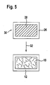
- eine schematische Darstellung von Verfahrensschritten zur Herstellung einer erfindungsgemäßen Trägervorrichtung;
- Figur 6
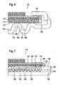
- eine schematische Schnittdarstellung eines dritten Ausführungsbeispiels eines erfindungsgemäßen Brennstoffzellemoduls; und
- Figur 7
- eine schematische Schnittdarstellung eines vierten Ausführungsbeispiels eines erfindungsgemäßen Brennstoffzellenmoduls.
- Ein Ausführungsbeispiel einer erfindungsgemäßen Trägervorrichtung, welches in
Figur 1 gezeigt und dort mit 10 bezeichnet ist, ist plattenförmig ausgebildet. Die Trägervorrichtung 10 umfasst eine Rahmeneinrichtung 12 mit gegenüberliegenden, parallel beabstandeten Rahmenelementen 14a, 14b. Zu diesen Rahmenelementen 14a, 14b sind Rahmenelemente 16a, 16b quer und insbesondere senkrecht orientiert. Die Rahmenelemente 16a,16b sind beabstandet und insbesondere parallel beabstandet zueinander. - An der Rahmeneinrichtung 12 ist (mindestens) ein Fensterbereich 18 gehalten. Dieser Fensterbereich 18 ist einstückig mit den Rahmenelementen 14a, 14b, 16a und 16b verbunden. Er ist von der Rahmeneinrichtung 12 mit ihren Rahmenelementen 14a, 14b, 16a, 16b umgeben.
- Die Rahmeneinrichtung 12 ist aus einem Vollmaterial 19 hergestellt, welches gasundurchlässig ist.
- In der Rahmeneinrichtung 12 können dabei (im Vollmaterial) ein oder mehrere Kanäle 20 zur Fluiddurchführung angeordnet sein. Beispielsweise sind Kanäle 20 an den Rahmenelementen 14a und 14b gebildet. Die Kanäle 20 sind insbesondere als durchgehende Ausnehmungen ausgebildet.
- Der Fensterbereich 18 ist aus einem offenporösen Material 22 hergestellt, so dassder Fensterbereich 18 gasdurchlässig ist (was in
Figur 2 durch die Pfeile mit dem Bezugszeichen 24 angedeutet ist). Außerhalb des Fensterbereiches 18 ist die Trägervorrichtung 10 durch das Vollmaterial 19 der Rahmeneinrichtung 12 nichtgasdurchlässig. (Eine eventuelle Gasdurchlässigkeit kommt allein durch "makroskopische" Kanäle in der Form von Durchbohrungen oder Dergleichen zustande.) - Die Trägervorrichtung 10 mit der Rahmeneinrichtung 12 und dem Fensterbereich 18 ist aus einem (dem gleichen) elektrisch leitfähigen Material hergestellt. Insbesondere sind die Rahmeneinrichtung 12 und der Fensterbereich 18 aus einem ferritischen Stahl hergestellt, welcher beispielsweise einen Chromanteil von 17 % bis 28 % enthält und einen Mangananteil enthält. Auch der Fensterbereich 18 stellt einen elektrischen Kontaktpfad durch die poröse Ausbildung (und damit nicht-vollständige Öffnung) bereit.
- Der Fensterbereich 18 ist integral an der Rahmeneinrichtung 12 gebildet, so dass keine zusätzliche Verbindungseinrichtung wie eine Lötverbindung, Schweißverbindung oder Klebeverbindung notwendig ist. Die Rahmeneinrichtung 12 und der Fensterbereich 18 werden insbesondere integral beispielsweise pulvermetallurgisch hergestellt.
- Bei einem Ausführungsbeispiel eines Herstellungsverfahrens, welches schematisch in
Figur 5 gezeigt ist, werden unterschiedliche Ausgangsmaterialien 26,28 verwendet; das Ausgangsmaterial 26 wird für die Herstellung der Rahmeneinrichtung 12 verwendet und das Ausgangsmaterial 28 für die Herstellung des Fensterbereichs 18. Das Ausgangsmaterial 26 und das Ausgangsmaterial 28 umfasst jeweils Metallpulver und ein Bindemittel. Der Bindemittelanteil ist in dem Ausgangsmaterial 28 höher als in dem Ausgangsmaterial 26. Der Bindemittelanteil ist so gewählt, dass nach dem Sintern die Rahmeneinrichtung mit Vollmaterial gasundurchlässig ist und der Fensterbereich porös gasdurchlässig ist. - Aus dem Ausgangsmaterial 26 und dem Ausgangsmaterial 28 wird ein Vorkörper 30 hergestellt. Dazu wird das Ausgangsmaterial 26 und das Ausgangsmaterial 28 entsprechend der herzustellenden Form der Rahmeneinrichtung 12 und des (mindestens einen) Fensterbereichs 18 positioniert.
- BeieinemAusführungsbeispielerfolgteineVerpressung und eine anschließende Aushärtung zur Bildung eines Grünkörpers.
- Es ist auch möglich, über ein PIM-Verfahren (PIM - Powder Injection Molding) durch Spritzguss das Ausgangsmaterial 26 und das Ausgangsmaterial 28 entsprechend zu positionieren.
- Es ist beispielsweise auch möglich, bei einem Foliengießverfahren über entsprechende Positionierung von Pasten an dem Ausgangsmaterial 26 und dem Ausgangsmaterial 28 den Vorkörper 30 herzustellen.
- Der Vorkörper 30 (Grünkörper) wird gesintert. Dies ist in
Figur 5 schematisch durch den Pfeil mit dem Bezugszeichen 32 dargestellt. Durch Wärmebehandlung erfolgt an dem Ausgangsmaterial 28 eine Porenbildung und der Fensterbereich 18 wird hergestellt. Dieser ist von der Rahmeneinrichtung 12 umgeben, wobei der Fensterbereich 18 integral an der Rahmeneinrichtung 12 gebildet ist. - Man erhält dann die Trägervorrichtung 10. Diese ist als Sinterplatte ausgebildet. Da sie aus elektrisch leitfähigem Material hergestellt ist, lässt sich diese auch als Bipolarplatte einsetzen, um beispielsweise an einer Seite direkt oder indirekt eine Kathode zu kontaktieren und auf einer anderen Seite direkt oder indirekt eine Anode zu kontaktieren.
- Die spezielle Ausbildung der Rahmeneinrichtung 12 und des oder der Fensterbereiche 18 ist angepasst an die spezielle Anwendung. Es können beispielsweise mehrere Fensterbereiche vorgesehen sein, welche von den entsprechenden Rahmenelementen der Rahmeneinrichtung umgeben sind.
- Integral mit der Herstellung lassen sich auf der Trägervorrichtung 10 auch eine oder mehrere weitere Schichten herstellen. Beispielsweise lassen sich direkt integral während der Herstellung der Trägervorrichtung 10 auf dem Fensterbereich 18 und/oder der Rahmeneinrichtung 12 eine oder mehrere keramische Schichten anordnen. Dazu werden für die Herstellung des Vorkörpers 30 eine oder mehrere weitere Schichten an einem weiteren Ausgangsmaterial auf entsprechenden Bereichen positioniert.
- Die Trägervorrichtung 10 lässt sich beispielsweise als Bipolarplatte oder Interkonnektor für eine Hochtemperatur-Brennstoffzelle und insbesondere oxidkeramische Brennstoffzelle (SOFC-Brennstoffzelle) einsetzen.
- Die Trägervorrichtung 10 kann als Substrat für eine elektrochemische Funktionseinrichtung dienen. Beispielsweise ist aufderTrägervorrichtung 10 direkt ein elektrisch leitfähiges Trägersubstrat für eine Anode angeordnet oder die Anode ist direkt an dem Fensterbereich 18 der Trägervorrichtung 10 angeordnet.
- Es ist grundsätzlich auch möglich, dass die Trägervorrichtung ein Trägersubstrat für eine Kathode ist.
- Ein erstes Ausführungsbeispiel eines Brennstoffzellenmoduls, welches in
Figur 3 gezeigt und dort mit 34 bezeichnet ist, weist eine Trägervorrichtung 10 mit der Rahmeneinrichtung 12 und dem Fensterbereich 18 auf. - Das Brennstoffzellenmodul 34 umfasst ein Gehäuse 36 aus einem metallischen Material mit einem ersten Gehäuseteil 38 und einem zweiten Gehäuseteil 40. Der erste Gehäuseteil 38 weist eine im Wesentlichen ebene Innenseite 42 auf. An dieser Innenseite 42 ist eine elektrische Kontakteinrichtung 44 angeordnet. Die Trägervorrichtung 10 stützt sich auf der elektrischen Kontakteinrichtung 44 ab und ist mit dieser beispielsweise durch Verlötung verbunden. Die elektrische Kontakteinrichtung 44 ist selber mit dem ersten Gehäuseteil 38 beispielsweise durch Verlötung verbunden.
- Die elektrische Kontakteinrichtung 44 ist so ausgebildet, dass sie einen elektrischen Kontakt zwischen dem Gehäuse 36 und einer Anode 46 einer elektrochemischen Funktionseinrichtung 48 herstellt, welche auf der Trägervorrichtung 10 angeordnet ist. Sie ist gasdurchlässig ausgebildet, so dass Reaktionsgase durch die elektrische Kontakteinrichtung 44 hindurch und durch den Fensterbereich 18 der Trägervorrichtung 10 zu der Anode 46 gelangen können, so dass dort elektrochemische Zellreaktionen durchführbar sind. Die elektrochemische Kontakteinrichtung 44 ist beispielsweise als Netz oder Gewebe oder Gewirke ausgebildet.
- Zwischen der Trägervorrichtung 10 und der Innenseite 42 des Gehäuses 36 ist ein Anodenraum 50 gebildet, in welchen beispielsweise über Kanäle 20 Reaktionsgase (Brennstoffgase) einkoppelbar sind und über den die Anode 46 mit Reaktionsgasen versorgbar ist.
- Die elektrochemische Funktionseinrichtung 48 ist über eine Anoden-Elektrolyt-Kathoden-Einheit 52 gebildet. Sie umfasst die Anode 46, welche beispielsweise aus einem oxidkeramischen Material wie Yttrium-stabilisiertem Zirkonoxid und Nickel als Katalysator hergestellt ist.
- Auf der Anode 46 ist eine Elektrolytschicht mit einem gasundurchlässigen Elektrolyten 54 angeordnet. Dieser Elektrolyt 54 ist für Elektronen nicht leitfähig. Er ist jedoch sauerstoffionenleitend. Er ist insbesondere aus einem keramischen Material hergestellt wie beispielsweise aus Yttrium-stabilisiertem Zirkonoxid.
- Auf dem Elektrolyten 54 ist eine Kathode 56 angeordnet. Diese ist aus einem oxidkeramischen Material hergestellt. Beispielsweise werden zur Herstellung Mischoxide wie Lanthan-Strontium-Manganat eingesetzt.
- Bei einer Hochtemperatur-Brennstoffzelle finden an der Kathode 56 folgende Zellreaktionen statt:

- Der Anode 46 wird Brennstoff zugeführt. Es finden folgende Zellreaktionen statt:
H 2+O 2→ H 2 O + 2e-
- Die entsprechende Brennstoffzelle wird bei einer Temperatur im Bereich von ca. 650°C bis 1000°C betrieben.
- Der Brennstoff (welcher Wasserstoffgas ist oder enthält), kann beispielsweise über einen Reformer geliefert werden.
- Der zweite Gehäuseteil 40 ist teilweise überlappend zu der Trägervorrichtung 10 angeordnet. Er weist einen Ü berlappbereich 58 auf, welcher seitlich beabstandet zu der Kathode 56 ist und oberhalb der Innenseite 42 liegt. Dieser Überlappbereich 58 ragt von einer Seitenwand 60 weg. Der Überlappbereich 58 ist vorzugsweise mindestens näherungsweise parallel zu der Innenseite 42 und quer und beispielsweise senkrecht zu der Seitenwand 60 angeordnet. Der zweite Gehäuseteil 40 und dererste Gehäuseteil 38 liegen dabei auf demselben elektrischen Potential. Sie sind entsprechend miteinander verbunden; beispielsweise sind sie einstückig miteinander verbunden.
- Bei einem Ausführungsbeispiel ist die Trägervorrichtung 10 über eine Lotschicht 62 elektrisch leitend mit dem Überlappbereich 58 des zweiten Gehäuseteils 40 verbunden. Die Lotschicht 62 ist dabei auf der Rahmeneinrichtung 12 angeordnet. Sie liegt ferner an Stirnseiten 64, 66 der Anode 46 und des Elektrolyten 54. Weiterhin liegt sie an einer Oberseite 68 des Elektrolyten 54. Diese Lotschicht62 istdabei umlaufend ausgebildet. Sie stellt neben der elektrischen Kontaktierung zwischen dem Gehäuse 36 und der Anode 46 (über deren Stirnseite 64) und der elektrischen Kontaktierung der Trägervorrichtung 10 zusätzlich zu der elektrischen Kontakteinrichtung 44 eine Fluddichtung bereit, welche den Anodenraum 50 gegenüber der Kathode 56 abdichtet. Weiterhin sorgt sie für eine mechanische Fixierung der Trägervorrichtung 10 und derelektrochemischen Funktionseinrichtung im Gehäuse 36.
- Über die Lotschicht 62 erfolgt eine elektrische Kontaktierung der Anode 46 (direkt über die Stirnseite 64 und indirekt über die Lotschicht 62 an der Rahmeneinrichtung 12 über die Trägervorrichtung 10) zusätzlich zu der elektrischen Kontakteinrichtung 44.
- Durch diese zusätzliche Kontaktierung wird insgesamt ein weiterer elektronischer Leitungspfad zusätzlich zu dem elektronischen Leitungspfad über die elektrische Kontakteinrichtung 44 bereitgestellt.
- Durch die Positionierung der Lotschicht 62 auf der Rahmeneinrichtung 12 wird der Fensterbereich 18 nicht verringert.
- Mehrere Brennstoffzellenmodule 34 lassen sich zu einem Brennstoffzellenstapel aneinanderfügen. Beispielsweise kontaktiert dazu die Kathode 56 das Gehäuse 36 einer benachbarten Brennstoffzelle.
- Es ist grundsätzlich möglich, dass das Brennstoffzellenmodul einen umgekehrten Aufbau bezüglich der Anordnung von Anode, Elektrolyt und Kathode hat. Die Kathode kann auf einem Kathodenträger als erste Schicht angeordnet sein. Auf der Kathode ist die Elektrolytschicht angeordnet und die Anode ist als letzte Schicht auf dem Elektrolyt angeordnet.
- Bei einem zweiten Ausführungsbeispiel eines
- Brennstoffzellemoduls, welches schematisch in
Figur 4 gezeigt und dort mit 70 bezeichnet ist, ist in einem Gehäuse 72, welches beispielsweise gleich ausgebildet ist wie das Gehäuse 36, eine Trägervorrichtung 74 angeordnet. Diese weist eine Rahmeneinrichtung 76 auf, an welcher integral eine elektrische Kontakteinrichtung 78 gebildet ist. Über diese elektrische Kontakteinrichtung 78 stützt sich die Trägervorrichtung 74 an einer Innenseite 80 des Gehäuses 72 mechanisch ab, wobei gleichzeitig beispielsweise durch eine Lötverbindung ein elektrischer Kontakt hergestellt ist. - Die elektrische Kontakteinrichtung 78 ist beispielsweise durch Stützfüße 82 gebildet, welche an der Rahmeneinrichtung 76 angeordnet und insbesondere einstückig gebildet sind.
- Die Rahmeneinrichtung 76 hält einen oder mehrere Fensterbereiche 84, welche eine Unterseite 86 aufweisen, die zu der Innenseite 80 des Gehäuses 72 beabstandet ist. DieserAbstand wird durch die Stützfüße 82 erreicht. Durch die Beabstandung der Unterseite 86 der Fensterbereiche 84 und der Innenseite 80 ist in dem Gehäuse 72 ein Anodenraum 88 gebildet. Über den Anodenraum können Brennstoffgase zu den Fensterbereichen 84 zugeführt werden und durch das poröse Material dieser Fensterbereiche 84 zu einer Anode 90 einer Anoden-Elektrolyt-Kathoden-Einheit 92 gelangen.
- Bei dem beschriebenen Ausführungsbeispiel ist die elektrische Kontakteinrichtung 78 in die Trägervorrichtung 74 integriert.
- Ansonsten funktioniert das Brennstoffzellenmodul 70 wie oben anhand des Brennstoffzellenmoduls 34 beschrieben.
- Durch die erfindungsgemäße Lösung wird eine Trägervorrichtung für eine elektrochemische Funktionseinrichtung bereitgestellt, welche elektrisch leitfähig ist (für Elektronenleitung). Die Trägervorrichtung lässt sich dadurch als Bipolarplatte oder Interkonnektor ausbilden. Sie kann elektrochemische Funktionsschichten tragen. Beispielsweise ist auf der Trägervorrichtung 10 direkt ein Anodensubstrat angeordnet oder eine Anödenschicht.
- Der oder die Fensterbereiche18 sind dann direkt in die Rahmeneinrichtung 12 integriert. Es ist dazu kein nachträgliches Löten oder Schweißen notwendig. Ein Löten oder Schweißen kann zu Spannungen führen, welche zu einem Verzug führen können. Unebene Teile sind nicht geeignet für den Aufbau eines Brennstoffzellenstapels. Durch die erfindungsgemäße Lösung einer integralen Trägervorrichtung 10 sind Probleme mit Übergängen an Lötstellen bzw. Schweißverbindungen vermieden; es entstehen keine Sprünge im Ausdehnungskoeffizienten, der Spannungsverteilung, Legierungsanteile usw. Dadurch entstehen auch keine Probleme mit keramischen Schichten, welche auf der Trägervorrichtung 10 angeordnet sind, da diese keramischen Schichten nicht an Lötstellen bzw. Schweißstellen angeordnet sind.
- Die Trägervorrichtung 10 weist keine Sprünge im thermischen Ausdehnungskoeffizienten, in der Spannungsverteilung, in den Legierungsanteilen usw. auf. Sie lässt sich auf einfache Weise mit einer Minimierung der Anzahl der Herstellungsschritte herstellen. Der für die Herstellung eines Fensterbereichs 18 notwendige Herstellungsschritt wird gleichzeitig für die Herstellung der Rahmeneinrichtung 12 genutzt.
- Ein drittes Ausführungsbeispiel eines erfindungsgemäßen Brennstoffzellenmoduls, welches in Figur 6 gezeigt und dort mit 94 bezeichnet ist, umfasst ein Gehäuse 95 mit einem ersten Gehäuseteil 96 und einem zweiten Gehäuseteil 98. Der zweite Gehäuseteil 98 ist grundsätzlich gleich ausgebildet wie der zweite Gehäuseteil 40 bei dem Brennstoffzellenmodul 34.
- Der erste Gehäuseteil 96 weist einen Bodenbereich 100 auf, welcher "wellig" ausgebildet ist. Eine Innenseite 102 dieses Bodenbereichs 100 umfasst beabstandete Erhebungen 104, zwischen welchen Kanäle 106 gebildet sind. Die Kanäle 106 sind dabei derart miteinander verbunden, dass ein Anodenraum 108 gebildet ist. Der Anodenraum 108 ist durch den zweiten Gehäuseteil 98 nach oben geschlossen.
- Die Erhebungen 104 weisen eine Einhüllende 110 auf, welche im Wesentlichen eine Ebene ist.
- An den Erhebungen 104 ist ein Anodenträger 112 angeordnet. Er ist mit den Erhebungen 104 beispielsweise durch Schweißen oder Löten verbunden.
- Auf dem Anodenträger sitzt eine elektrochemische Funktionseinrichtung mit einer Anode, einer Elektrolytschicht und einer Kathode. Der Aufbau des Anodenträgers, welcher durch eine erfindungsgemäße Trägervorrichtung gebildet ist, und der elektrochemischen Funktionseinrichtung sowie die Verbindung mit dem zweiten Gehäuseteil98 istdabeigrundsätzlichgleichwie bei dem Ausführungsbeispiel 34 beschrieben.
- Bei dem Brennstoffzellenmodul 94 ist die Trägervorrichtung 114 (welche dem Anodenträger 112 entspricht) direkt an dem ersten Gehäuseteil 96 abgestützt. Eine elektrische Kontakteinrichtung entsprechend der elektrischen Kontakteinrichtung 44 ist nicht vorgesehen.
- Der erste Gehäuseteil 96 ist als Gasverteiler ausgebildet. Der Gasverteiler, welcher durch die Erhebungen 104 an der Innenseite 102 des ersten Gehäuseteils 96 gebildet ist, ist ein Gasverteiler für Brennstoffgas.
- Auf einer der Innenseite 102 gegenüberliegenden Außenseite 116 ist ebenfalls ein Gasverteiler gebildet. Mit der Außenseite 116 lässt sich eine Kathode eines benachbarten Brennstoffzellenmoduls verbinden, wobei durch die entsprechenden Kanäle an der Außenseite 116 die Kathode mit Oxidatorgas versorgbar ist.
- Ansonsten entspricht die Funktionsweise des Brennstoffzellenmoduls 94 der Funktionsweise des Brennstoffzellenmoduls 34.
- Bei einem vierten Ausführungsbeispiel eines erfindungsgemäßen Brennstoffzellenmoduls, welches in
Figur 7 gezeigt und dort mit 118 bezeichnet ist, ist ein Gehäuse 120 mit einem ersten Gehäuseteil 122 vorgesehen. Der erste Gehäuseteil 122 ist als Unterschale ausgebildet. Der erste Gehäuseteil 122 umfasst einen umlaufenden hochgezogenen Randbereich 124 mit einer im Wesentlichen ebenen Stirnfläche 126. Auf die Stirnfläche aufgelegt sitzt eine Trägervorrichtung 128, welche mit dem Randbereich 124 des ersten Gehäuseteils 122 beispielsweise durch Löten oder Schweißen verbunden ist. Die Trägervorrichtung 128 ist dabei mit einem gasundurchlässigen Rahmenbereich 130 auf den Randbereich 124 aufgesetzt. - An dem Rahmenbereich 130 ist integral ein poröser gasdurchlässiger Fensterbereich 132 gebildet.
- Die Trägervorrichtung 128 bildet insbesondere mit ihrem Rahmenbereich 130 einen zweiten Gehäuseteil 134. Durch die Trägervorrichtung 128 als zweiten Gehäuseteil 134 und den ersten Gehäuseteil 122 mit seinem hochgezogenen Randbereich 124 ist ein Anödenraum 136 begrenzt. In diesem ist eine elektrische Kontakteinrichtung 138 angeordnet, welche grundsätzlich wie die oben beschriebene elektrische Kontakteinrichtung 44 funktioniert. Die elektrische Kontakteinrichtung 138 ist insbesondere mit dem ersten Gehäuseteil 122 verbunden und mit der Trägervorrichtung 128 verbunden.
- Es ist grundsätzlich möglich, dass der erste Gehäuseteil 122 direkt mit der Trägervorrichtung 128 verbunden ist.
- Auf der Trägervorrichtung 128 ist eine Anode 140 angeordnet. Diese sitzt insbesondere an dem Fensterbereich 132, ohne über diesen hinauszuragen.
- Die Anode 140 ist durch eine Elektrolytschicht 142 überdeckt. Die Elektrolytschicht 142 läuft dabei über eine Seitenfläche 144 der Anode 140 in den Rahmenbereich 130, das heißt die Elektrolytschicht 142 weist einen Bereich 146 auf, welcher auf dem Rähmenbereich 130 der Trägervorrichtung 128 liegt.
- Die Elektrolytschicht 142 ist gasdicht. Sie deckt die Anode 140oben nach außen ab und über den Bereich 146 seitlich nach außen ab. Da der Bereich 146 auf den Rahmenbereich 130 aufgesetzt ist, kann seitlich kein Brennstoffgas aus dem Fensterbereich 132 direkt auf die Kathodenseite gelangen oderdurch die Anode 140 durch auf die Kathodenseite gelangen.
- Es ist grundsätzlich auch möglich, dass die Elektrolytschicht 142 den Rahmenbereich 130 nach oben vollständig abdeckt. Dadurch lässt sich die Isolationswirkung bezüglich elektronischer Leitung des Brennstoffzellenmoduls 118 zu einem benachbarten Brennstoffzellenmodul erhöhen.
- Der Flächenbereich, welcher durch die Elektrolytschicht 142 abgedeckt wird, ist größer als der Flächenbereich des Fensterbereichs 132 und ist auch größer als der Flächenbereich der Anode 140.
- Ansonsten funktioniert das Brennstoffzellenmodul 118 wie oben beschrieben.
Claims (15)
- Trägervorrichtung für eine elektrochemische Funktionseinrichtung einer Hochtemperatur-Brennstoffzelle (52), umfassend eine Rahmeneinrichtung (12) aus einem elektrisch leitfähigen Material und mindestens einen Fensterbereich (18) aus einem elektrisch leitfähigen Material, welcher an der Rahmeneinrichtung (12) integral gebildet ist und einstückig an der Rahmeneinrichtung (12) angeordnet ist, wobei der mindestens eine Fensterbereich (18) aus einem porösen Material hergestellt ist und über die Porosität gasdurchlässig ist und wobei die Rahmeneinrichtung (12) im Vollmaterial gasundurchlässig ist, wobei die Trägervorrichtung pulvermetallurgisch hergestellt ist und unterschiedliche Ausgangsmaterialien (26, 28) für die Herstellung der Rahmeneinrichtung (12) und des Fensterbereichs (18) verwendet sind, wobei die Ausgangsmaterialien (26, 28) Metallpulver und Bindemittel umfassen und der Bindemittelanteil in dem Ausgangsmaterial (28) für den Fensterbereich (18) höher ist als in dem Ausgangsmaterial (26) für die Rahmeneinrichtung (12).
- Trägervorrichtung nach Anspruch 1, gekennzeichnet durch einen oder mehrere Stützfüße (82), wobei insbesondere ein oder mehrere Stützfüße (82) an der Rahmeneinrichtung (12) angeordnet sind, und wobei vorzugsweise die Stützfüße (82) so angeordnet und ausgebildet sind, dass unterhalb des mindestens einen Fensterbereichs (18) ein Gasraum ausbildbar ist.
- Trägervorrichtung nach einem der vorangehenden Ansprüche, gekennzeichnet durch eine Ausbildung als Bipolarplatte und/oder als Interkonnektor.
- Trägervorrichtung nach einem der vorangehenden Ansprüche, dadurch gekennzeichnet, dass an der Rahmeneinrichtung (12) eine elektrische Kontakteinrichtung (78) angeordnet ist, über die die Rahmeneinrichtung (12) an einem Gehäuse (72) abstützbar ist.
- Trägervorrichtung nach einem der vorangehenden Ansprüche, dadurch gekennzeichnet, dass an dem mindestens einen Fensterbereich (18) mindestens eine elektrochemische Funktionsschicht angeordnet ist, wobei insbesondere die mindestens eine elektrochemische Funktionsschicht integral mit dem Fensterbereich (18) hergestellt ist, und wobei vorzugsweise die mindestens eine elektrochemische Funktionsschicht eine Anodenschicht oder Kathodenschicht ist, und insbesondere die mindestens eine elektrochemische Funktionsschicht eine poröse Anodensubstratschicht oder poröse Kathodensubstratschicht ist.
- Trägervorrichtung nach einem der vorangehenden Ansprüche, dadurch gekennzeichnet, dass an der Rahmeneinrichtung (12) ein oder mehrere Kanäle (20) angeordnet sind, wobei insbesondere ein Kanal (20) als durchgehende Öffnung ausgebildet ist.
- Trägervorrichtung nach einem der vorangehenden Ansprüche, gekennzeichnet durch eine Ausbildung als Platte und insbesondere als Sinterplatte.
- Trägervorrichtung nach einem der vorangehenden Ansprüche, gekennzeichnet durch eine Herstellung der Rahmeneinrichtung (12) und des mindestens einen Fensterbereichs (18) aus Stahl.
- Hochtemperatur-Brennstoffzellenmodul, umfassend eine elektrochemische Funktionseinrichtung (52; 92) und eine Trägervorrichtung (10; 74; 114; 128) gemäß einem der vorangehenden Ansprüche, wobei die elektrochemische Funktionseinrichtung (52; 92) an der Trägervorrichtung (10; 74; 114; 128) angeordnet ist.
- Hochtemperatur-Brennstoffzellenmodul nach Anspruch 9, gekennzeichnet durch ein Gehäuse (36; 72; 95; 120), wobei insbesondere die Trägervorrichtung (10; 74; 114) an dem Gehäuse (36; 72; 95) angeordnet ist oder die Trägervorrichtung (114) Teil des Gehäuses (120) ist.
- Hochtemperatur-Brennstoffzellenmodul nach Anspruch 10, dadurch gekennzeichnet, dass die Trägervorrichtung (128) ein Deckelelement des Gehäuses (120) bildet, welches einen Elektrodenraum (136) abschließt.
- Hochtemperatur-Brennstoffzellenmodul nach Anspruch 10 oder 11, dadurch gekennzeichnet, dass eine gasdichte Elektrolytschicht (142) den mindestens einen Fensterbereich (132) vollständig überdeckt.
- Hochtemperatur-Brennstoffzellenmodul nach einem der Ansprüche 10 bis 12, dadurch gekennzeichnet, dass die Rahmeneinrichtung (12; 76; 130) mit dem Gehäuse (36; 72) oder einem Gehäuseteil (122) verlötet ist.
- Hochtemperatur-Brennstoffzellenmodul nach Anspruch 13, dadurch gekennzeichnet, dass die Rahmeneinrichtung (76) an gegenüberliegenden Seiten mit dem Gehäuse (72) verlötet ist.
- Verfahren zur Herstellung einer Trägervorrichtung für eine elektrochemische Funktionseinrichtung einer Hochtemperatur-Brennstoffzelle, bei dem aus elektrisch leitfähigem Material eine im Vollmaterial gasundurchlässige Rahmeneinrichtung hergestellt wird und an der Rahmeneinrichtung mindestens ein poröser, gasdurchlässiger Fensterbereich einstückig hergestellt wird, wobei die Rahmeneinrichtung und der mindestens eine Fensterbereich pulvermetallurgisch aus dem gleichen Material hergestellt werden.
Applications Claiming Priority (2)
| Application Number | Priority Date | Filing Date | Title |
|---|---|---|---|
| DE102007024225A DE102007024225A1 (de) | 2007-05-11 | 2007-05-11 | Trägervorrichtung für eine elektrochemische Funktionseinrichtung, Brennstoffzellenmodul und Verfahren zur Herstellung einer Trägervorrichtung |
| PCT/EP2008/055614 WO2008138824A1 (de) | 2007-05-11 | 2008-05-07 | Trägervorrichtung für eine elektrochemische funktionseinrichtung, brennstoffzellenmodul und verfahren zur herstellung einer trägervorrichtung |
Publications (4)
| Publication Number | Publication Date |
|---|---|
| EP2149171A1 EP2149171A1 (de) | 2010-02-03 |
| EP2149171B1 EP2149171B1 (de) | 2013-11-20 |
| EP2149171B8 EP2149171B8 (de) | 2014-03-12 |
| EP2149171B3 true EP2149171B3 (de) | 2015-07-29 |
Family
ID=39673150
Family Applications (1)
| Application Number | Title | Priority Date | Filing Date |
|---|---|---|---|
| EP08750135.9A Active EP2149171B3 (de) | 2007-05-11 | 2008-05-07 | Trägervorrichtung für eine elektrochemische funktionseinrichtung, brennstoffzellemodul und verfahren zur herstellung einer trägervorrichtung |
Country Status (7)
| Country | Link |
|---|---|
| US (1) | US20100086828A1 (de) |
| EP (1) | EP2149171B3 (de) |
| JP (1) | JP2010527102A (de) |
| KR (1) | KR20100016448A (de) |
| DE (1) | DE102007024225A1 (de) |
| DK (1) | DK2149171T6 (de) |
| WO (1) | WO2008138824A1 (de) |
Families Citing this family (7)
| Publication number | Priority date | Publication date | Assignee | Title |
|---|---|---|---|---|
| DE102007034967A1 (de) | 2007-07-26 | 2009-01-29 | Plansee Se | Brennstoffzelle und Verfahren zu deren Herstellung |
| DE102011053550B4 (de) | 2011-09-13 | 2019-12-05 | Deutsches Zentrum für Luft- und Raumfahrt e.V. | Brennstoffzellenvorrichtung |
| DE102012103383A1 (de) * | 2012-04-18 | 2013-10-24 | Deutsches Zentrum für Luft- und Raumfahrt e.V. | Verfahren zur Herstellung eines Trägersubstrats, Trägersubstrat und elektrochemische Einrichtung |
| DE102013008473A1 (de) * | 2013-05-21 | 2014-11-27 | Plansee Composite Materials Gmbh | Brennstoffzelle |
| AT15927U1 (de) * | 2017-03-16 | 2018-09-15 | Plansee Se | Funktionalisiertes, poröses Gasführungsteil für elektrochemisches Modul |
| CN107658489A (zh) * | 2017-08-28 | 2018-02-02 | 清华大学 | 一种安装、拆卸方便的燃料电池模组 |
| JP2024132507A (ja) * | 2023-03-17 | 2024-10-01 | 株式会社東芝 | 電気化学セル、集電体、及びセルスタック |
Family Cites Families (21)
| Publication number | Priority date | Publication date | Assignee | Title |
|---|---|---|---|---|
| JPH04174973A (ja) * | 1990-06-20 | 1992-06-23 | Fuji Electric Co Ltd | 固体電解質型燃料電池 |
| WO1993013566A1 (en) * | 1991-12-26 | 1993-07-08 | International Fuel Cells, Inc. | Plate-shaped fuel cell component and a method of making the same |
| IT1270878B (it) * | 1993-04-30 | 1997-05-13 | Permelec Spa Nora | Migliorata cella elettrochimica utilizzante membrane a scambio ionico e piatti bipolari metallici |
| JPH08148170A (ja) * | 1994-11-17 | 1996-06-07 | Tokyo Gas Co Ltd | 固体高分子型燃料電池のシ−ル方法 |
| JP2922132B2 (ja) * | 1995-03-15 | 1999-07-19 | 株式会社東芝 | 固体高分子型燃料電池 |
| US5624769A (en) * | 1995-12-22 | 1997-04-29 | General Motors Corporation | Corrosion resistant PEM fuel cell |
| JPH10199551A (ja) * | 1997-01-06 | 1998-07-31 | Honda Motor Co Ltd | 燃料電池構造体およびその製造方法 |
| DE19815796C2 (de) | 1998-04-08 | 2000-06-08 | Forschungszentrum Juelich Gmbh | Brennstoffzellenstapel mit einer eine poröse Wand aufweisenden bipolaren Platte |
| DE19841919C2 (de) | 1998-09-12 | 2003-08-14 | Forschungszentrum Juelich Gmbh | Verfahren zur Herstellung eines Brennstoffzellenmoduls |
| EP1147243B1 (de) * | 1998-12-29 | 2003-11-19 | Proton Energy Systems, Inc. | Integrale gitter/rahmen-anordnung für eine elektrochemische zelle |
| DK174654B1 (da) * | 2000-02-02 | 2003-08-11 | Topsoe Haldor As | Faststofoxid brændselscelle og anvendelser heraf |
| JP2002042838A (ja) * | 2000-07-31 | 2002-02-08 | Honda Motor Co Ltd | 燃料電池、多孔質導電体・シール構造体の製造方法及び電極膜構造体の製造方法 |
| GB2368450B (en) * | 2000-10-25 | 2004-05-19 | Imperial College | Fuel cells |
| DE10161538B4 (de) | 2001-12-10 | 2004-09-09 | Deutsches Zentrum für Luft- und Raumfahrt e.V. | Träger für eine elektrochemische Funktionseinheit einer Hochtemperatur-Brennstoffzelle und Hochtemperatur-Brennstoffzelle |
| US20030232230A1 (en) * | 2002-06-12 | 2003-12-18 | Carter John David | Solid oxide fuel cell with enhanced mechanical and electrical properties |
| GB2422479B (en) * | 2003-04-15 | 2006-12-13 | Ceres Power Ltd | Solid oxide fuel cell with a novel substrate and a method for fabricating the same |
| DE10343652B4 (de) * | 2003-09-20 | 2005-09-29 | Elringklinger Ag | Verfahren zum Herstellen einer Lötverbindung zwischen einem Substrat und einem Kontaktelement einer Brennstoffzelleneinheit sowie Brennstoffzelleneinheit |
| DE202005020601U1 (de) | 2005-07-18 | 2006-04-27 | Elringklinger Ag | Brennstoffzelleneinheit |
| DE102005034616B4 (de) * | 2005-07-18 | 2008-07-03 | Elringklinger Ag | Brennstoffzelleneinheit und Brennstoffzellenstapel |
| DE102005045053A1 (de) * | 2005-09-21 | 2007-03-29 | Elringklinger Ag | Verfahren zum Herstellen einer Dichtungsanordnung für einen Brennstoffzellenstapel und Dichtungsanordnung für einen Brennstoffzellenstapel |
| DE102007026233A1 (de) * | 2007-05-31 | 2008-12-04 | Deutsches Zentrum für Luft- und Raumfahrt e.V. | Verfahren zur Herstellung einer gasdichten Festelektrolytschicht und Festelektrolytschicht |
-
2007
- 2007-05-11 DE DE102007024225A patent/DE102007024225A1/de not_active Ceased
-
2008
- 2008-05-07 WO PCT/EP2008/055614 patent/WO2008138824A1/de not_active Ceased
- 2008-05-07 EP EP08750135.9A patent/EP2149171B3/de active Active
- 2008-05-07 JP JP2010506925A patent/JP2010527102A/ja active Pending
- 2008-05-07 DK DK08750135.9T patent/DK2149171T6/en active
- 2008-05-07 KR KR1020097023542A patent/KR20100016448A/ko not_active Withdrawn
-
2009
- 2009-10-28 US US12/589,885 patent/US20100086828A1/en not_active Abandoned
Also Published As
| Publication number | Publication date |
|---|---|
| WO2008138824A1 (de) | 2008-11-20 |
| US20100086828A1 (en) | 2010-04-08 |
| DK2149171T3 (da) | 2014-02-10 |
| EP2149171A1 (de) | 2010-02-03 |
| EP2149171B1 (de) | 2013-11-20 |
| JP2010527102A (ja) | 2010-08-05 |
| EP2149171B8 (de) | 2014-03-12 |
| DK2149171T6 (en) | 2015-11-09 |
| DE102007024225A1 (de) | 2008-11-13 |
| KR20100016448A (ko) | 2010-02-12 |
Similar Documents
| Publication | Publication Date | Title |
|---|---|---|
| EP2149171B1 (de) | Trägervorrichtung für eine elektrochemische funktionseinrichtung, brennstoffzellemodul und verfahren zur herstellung einer trägervorrichtung | |
| EP2154742B1 (de) | Brennstoffzelleneinheit und Verfahren zum Herstellen einer elektrisch leitfähigen Verbindung zwischen einer Elektrode und einer Bipolarplatte | |
| DE19710345C1 (de) | Werkstoff für elektrische Kontaktschichten zwischen einer Elektrode einer Hochtemperatur-Brennstoffzelle und einem Verbindungselement | |
| DE202013012748U1 (de) | Elektrisch leitfähiges Element, Zellenstapel, elektrochemisches Modul und elektrochemische Vorrichtung | |
| DE4237602A1 (de) | Hochtemperatur-Brennstoffzellen-Stapel und Verfahren zu seiner Herstellung | |
| DE69233190T2 (de) | Zelleinheiten für Festoxidbrennstoffzellen und Energiegeneratoren die diese Zelleinheiten verwenden | |
| EP1662596B1 (de) | Dichtungsanordnung für einen Hochtemperatur Brennstoffzellenstapel und Verfahren zum Herstellen dieses Brennstoffzellenstapels | |
| EP0425939A1 (de) | Festelektrolyt-Hochtemperatur-Brennstoffzellenmodul | |
| DE19841919C2 (de) | Verfahren zur Herstellung eines Brennstoffzellenmoduls | |
| WO2008138787A1 (de) | Hochtemperatur-brennstoffzellenmodul und verfahren zur herstellung eines hochtemperatur-brennstoffzellenmoduls | |
| DE102022121234A1 (de) | Elektrochemischer Reaktionszellenstapel | |
| EP2054964B1 (de) | Wiederholeinheit für einen stapel elektrochemischer zellen, sowie stapelanordnung | |
| EP0667043B1 (de) | Verfahren zum dichten von hochtemperatur-brennstoffzellen und nach dem verfahren gedichtete brennstoffzelle | |
| DE102011000180A1 (de) | Anoden-Gestützte Flachrohr-SOFC und deren Herstellungsverfahren | |
| EP1923944B1 (de) | Silberbasislot mit Titanzusatz beinhaltende Dichtungsanordnung für eine Hochtemperaturbrennstoffzelle und Verfahren zur Herstellung eines Brennstoffzellenstapels | |
| EP1532706B1 (de) | Brennstoffzellen-stack | |
| DE10317388B4 (de) | Brennstoffzelle und/oder Elektrolyseur sowie Verfahren zu deren/dessen Herstellung | |
| DE102008036848A1 (de) | Verfahren zum Herstellen einer elektrisch leitfähigen Verbindung zwischen einer Elektrode und einer Bipolarplatte sowie Brennstoffzelleneinheit | |
| EP1665431B1 (de) | Interkonnektor für hochtemperatur-brennstoffzelleneinheit | |
| DE10350478B4 (de) | Brennstoffzelleneinheit | |
| WO2008138806A1 (de) | Brennstoffzellenmodul | |
| DE10125776A1 (de) | Dichtung | |
| DE10339613A1 (de) | Festoxidbrennstoffzelle und Verfahren zu ihrer Herstellung | |
| DE10330476B4 (de) | Brennstoffzelleneinheit und Verfahren zur Herstellung einer Brennstoffzelleneinheit | |
| DE10317359A1 (de) | Brennstoffzelle und/oder Elektrolyseur sowie Verfahren zu deren/dessen Herstellung |
Legal Events
| Date | Code | Title | Description |
|---|---|---|---|
| PUAI | Public reference made under article 153(3) epc to a published international application that has entered the european phase |
Free format text: ORIGINAL CODE: 0009012 |
|
| 17P | Request for examination filed |
Effective date: 20091125 |
|
| AK | Designated contracting states |
Kind code of ref document: A1 Designated state(s): AT BE BG CH CY CZ DE DK EE ES FI FR GB GR HR HU IE IS IT LI LT LU LV MC MT NL NO PL PT RO SE SI SK TR |
|
| AX | Request for extension of the european patent |
Extension state: AL BA MK RS |
|
| DAX | Request for extension of the european patent (deleted) | ||
| GRAP | Despatch of communication of intention to grant a patent |
Free format text: ORIGINAL CODE: EPIDOSNIGR1 |
|
| INTG | Intention to grant announced |
Effective date: 20130620 |
|
| GRAS | Grant fee paid |
Free format text: ORIGINAL CODE: EPIDOSNIGR3 |
|
| GRAA | (expected) grant |
Free format text: ORIGINAL CODE: 0009210 |
|
| AK | Designated contracting states |
Kind code of ref document: B1 Designated state(s): AT BE BG CH CY CZ DE DK EE ES FI FR GB GR HR HU IE IS IT LI LT LU LV MC MT NL NO PL PT RO SE SI SK TR |
|
| REG | Reference to a national code |
Ref country code: GB Ref legal event code: FG4D Free format text: NOT ENGLISH |
|
| REG | Reference to a national code |
Ref country code: CH Ref legal event code: EP |
|
| REG | Reference to a national code |
Ref country code: AT Ref legal event code: REF Ref document number: 642101 Country of ref document: AT Kind code of ref document: T Effective date: 20131215 |
|
| REG | Reference to a national code |
Ref country code: IE Ref legal event code: FG4D Free format text: LANGUAGE OF EP DOCUMENT: GERMAN |
|
| REG | Reference to a national code |
Ref country code: DE Ref legal event code: R096 Ref document number: 502008010978 Country of ref document: DE Effective date: 20140116 |
|
| REG | Reference to a national code |
Ref country code: SE Ref legal event code: TRGR |
|
| REG | Reference to a national code |
Ref country code: DK Ref legal event code: T3 Effective date: 20140207 |
|
| REG | Reference to a national code |
Ref country code: NL Ref legal event code: VDEP Effective date: 20131120 |
|
| REG | Reference to a national code |
Ref country code: LT Ref legal event code: MG4D |
|
| PG25 | Lapsed in a contracting state [announced via postgrant information from national office to epo] |
Ref country code: FI Free format text: LAPSE BECAUSE OF FAILURE TO SUBMIT A TRANSLATION OF THE DESCRIPTION OR TO PAY THE FEE WITHIN THE PRESCRIBED TIME-LIMIT Effective date: 20131120 Ref country code: NO Free format text: LAPSE BECAUSE OF FAILURE TO SUBMIT A TRANSLATION OF THE DESCRIPTION OR TO PAY THE FEE WITHIN THE PRESCRIBED TIME-LIMIT Effective date: 20140220 Ref country code: HR Free format text: LAPSE BECAUSE OF FAILURE TO SUBMIT A TRANSLATION OF THE DESCRIPTION OR TO PAY THE FEE WITHIN THE PRESCRIBED TIME-LIMIT Effective date: 20131120 Ref country code: NL Free format text: LAPSE BECAUSE OF FAILURE TO SUBMIT A TRANSLATION OF THE DESCRIPTION OR TO PAY THE FEE WITHIN THE PRESCRIBED TIME-LIMIT Effective date: 20131120 Ref country code: LT Free format text: LAPSE BECAUSE OF FAILURE TO SUBMIT A TRANSLATION OF THE DESCRIPTION OR TO PAY THE FEE WITHIN THE PRESCRIBED TIME-LIMIT Effective date: 20131120 Ref country code: IS Free format text: LAPSE BECAUSE OF FAILURE TO SUBMIT A TRANSLATION OF THE DESCRIPTION OR TO PAY THE FEE WITHIN THE PRESCRIBED TIME-LIMIT Effective date: 20140320 |
|
| PG25 | Lapsed in a contracting state [announced via postgrant information from national office to epo] |
Ref country code: ES Free format text: LAPSE BECAUSE OF FAILURE TO SUBMIT A TRANSLATION OF THE DESCRIPTION OR TO PAY THE FEE WITHIN THE PRESCRIBED TIME-LIMIT Effective date: 20131120 Ref country code: LV Free format text: LAPSE BECAUSE OF FAILURE TO SUBMIT A TRANSLATION OF THE DESCRIPTION OR TO PAY THE FEE WITHIN THE PRESCRIBED TIME-LIMIT Effective date: 20131120 |
|
| PG25 | Lapsed in a contracting state [announced via postgrant information from national office to epo] |
Ref country code: PT Free format text: LAPSE BECAUSE OF FAILURE TO SUBMIT A TRANSLATION OF THE DESCRIPTION OR TO PAY THE FEE WITHIN THE PRESCRIBED TIME-LIMIT Effective date: 20140320 |
|
| PG25 | Lapsed in a contracting state [announced via postgrant information from national office to epo] |
Ref country code: EE Free format text: LAPSE BECAUSE OF FAILURE TO SUBMIT A TRANSLATION OF THE DESCRIPTION OR TO PAY THE FEE WITHIN THE PRESCRIBED TIME-LIMIT Effective date: 20131120 |
|
| REG | Reference to a national code |
Ref country code: DE Ref legal event code: R055 Ref document number: 502008010978 Country of ref document: DE |
|
| PLCP | Request for limitation filed |
Free format text: ORIGINAL CODE: EPIDOSNLIM1 |
|
| REG | Reference to a national code |
Ref country code: DE Ref legal event code: R097 Ref document number: 502008010978 Country of ref document: DE |
|
| PG25 | Lapsed in a contracting state [announced via postgrant information from national office to epo] |
Ref country code: RO Free format text: LAPSE BECAUSE OF FAILURE TO SUBMIT A TRANSLATION OF THE DESCRIPTION OR TO PAY THE FEE WITHIN THE PRESCRIBED TIME-LIMIT Effective date: 20131120 Ref country code: PL Free format text: LAPSE BECAUSE OF FAILURE TO SUBMIT A TRANSLATION OF THE DESCRIPTION OR TO PAY THE FEE WITHIN THE PRESCRIBED TIME-LIMIT Effective date: 20131120 Ref country code: CZ Free format text: LAPSE BECAUSE OF FAILURE TO SUBMIT A TRANSLATION OF THE DESCRIPTION OR TO PAY THE FEE WITHIN THE PRESCRIBED TIME-LIMIT Effective date: 20131120 Ref country code: SK Free format text: LAPSE BECAUSE OF FAILURE TO SUBMIT A TRANSLATION OF THE DESCRIPTION OR TO PAY THE FEE WITHIN THE PRESCRIBED TIME-LIMIT Effective date: 20131120 |
|
| PLCQ | Request for limitation of patent found admissible |
Free format text: ORIGINAL CODE: 0009231 |
|
| PLBE | No opposition filed within time limit |
Free format text: ORIGINAL CODE: 0009261 |
|
| LIM1 | Request for limitation found admissible |
Free format text: SEQUENCE NO: 1; FILED DURING OPPOSITION PERIOD Filing date: 20140819 Effective date: 20140819 |
|
| 26N | No opposition filed |
Effective date: 20140821 |
|
| REG | Reference to a national code |
Ref country code: DE Ref legal event code: R097 Ref document number: 502008010978 Country of ref document: DE Effective date: 20140821 |
|
| PG25 | Lapsed in a contracting state [announced via postgrant information from national office to epo] |
Ref country code: LU Free format text: LAPSE BECAUSE OF FAILURE TO SUBMIT A TRANSLATION OF THE DESCRIPTION OR TO PAY THE FEE WITHIN THE PRESCRIBED TIME-LIMIT Effective date: 20140507 |
|
| REG | Reference to a national code |
Ref country code: CH Ref legal event code: PL |
|
| PG25 | Lapsed in a contracting state [announced via postgrant information from national office to epo] |
Ref country code: MC Free format text: LAPSE BECAUSE OF FAILURE TO SUBMIT A TRANSLATION OF THE DESCRIPTION OR TO PAY THE FEE WITHIN THE PRESCRIBED TIME-LIMIT Effective date: 20131120 Ref country code: CH Free format text: LAPSE BECAUSE OF NON-PAYMENT OF DUE FEES Effective date: 20140531 Ref country code: LI Free format text: LAPSE BECAUSE OF NON-PAYMENT OF DUE FEES Effective date: 20140531 |
|
| PLCO | Limitation procedure: reply received to communication from examining division + time limit |
Free format text: ORIGINAL CODE: EPIDOSNLIR3 |
|
| REG | Reference to a national code |
Ref country code: IE Ref legal event code: MM4A |
|
| PG25 | Lapsed in a contracting state [announced via postgrant information from national office to epo] |
Ref country code: SI Free format text: LAPSE BECAUSE OF FAILURE TO SUBMIT A TRANSLATION OF THE DESCRIPTION OR TO PAY THE FEE WITHIN THE PRESCRIBED TIME-LIMIT Effective date: 20131120 |
|
| REG | Reference to a national code |
Ref country code: CH Ref legal event code: PK Free format text: DER EINTRAG ' BESCHRAENKUNG BEANTRAGT' WURDE IRRTUEMLICH ZWEIMAL EINGETRAGEN |
|
| REG | Reference to a national code |
Ref country code: DE Ref legal event code: R056 Ref document number: 502008010978 Country of ref document: DE |
|
| PLCR | Communication despatched that request for limitation of patent was allowed |
Free format text: ORIGINAL CODE: 0009245 |
|
| PG25 | Lapsed in a contracting state [announced via postgrant information from national office to epo] |
Ref country code: IE Free format text: LAPSE BECAUSE OF NON-PAYMENT OF DUE FEES Effective date: 20140507 Ref country code: IT Free format text: LAPSE BECAUSE OF FAILURE TO SUBMIT A TRANSLATION OF THE DESCRIPTION OR TO PAY THE FEE WITHIN THE PRESCRIBED TIME-LIMIT Effective date: 20131120 |
|
| REG | Reference to a national code |
Ref country code: DE Ref legal event code: R056 Ref document number: 502008010978 Country of ref document: DE Effective date: 20150330 |
|
| PLCN | Payment of fee for limitation of patent |
Free format text: ORIGINAL CODE: EPIDOSNRAL3 |
|
| PUAM | (expected) publication of b3 document |
Free format text: ORIGINAL CODE: 0009410 |
|
| STAA | Information on the status of an ep patent application or granted ep patent |
Free format text: STATUS: THE PATENT HAS BEEN LIMITED |
|
| REG | Reference to a national code |
Ref country code: DE Ref legal event code: R082 Ref document number: 502008010978 Country of ref document: DE Representative=s name: HOEGER, STELLRECHT & PARTNER PATENTANWAELTE MB, DE |
|
| REG | Reference to a national code |
Ref country code: CH Ref legal event code: AELM |
|
| REG | Reference to a national code |
Ref country code: SE Ref legal event code: REB3 Effective date: 20150729 |
|
| PG25 | Lapsed in a contracting state [announced via postgrant information from national office to epo] |
Ref country code: MT Free format text: LAPSE BECAUSE OF FAILURE TO SUBMIT A TRANSLATION OF THE DESCRIPTION OR TO PAY THE FEE WITHIN THE PRESCRIBED TIME-LIMIT Effective date: 20131120 |
|
| REG | Reference to a national code |
Ref country code: FR Ref legal event code: PLFP Year of fee payment: 9 |
|
| PG25 | Lapsed in a contracting state [announced via postgrant information from national office to epo] |
Ref country code: BG Free format text: LAPSE BECAUSE OF FAILURE TO SUBMIT A TRANSLATION OF THE DESCRIPTION OR TO PAY THE FEE WITHIN THE PRESCRIBED TIME-LIMIT Effective date: 20131120 |
|
| PG25 | Lapsed in a contracting state [announced via postgrant information from national office to epo] |
Ref country code: GR Free format text: LAPSE BECAUSE OF FAILURE TO SUBMIT A TRANSLATION OF THE DESCRIPTION OR TO PAY THE FEE WITHIN THE PRESCRIBED TIME-LIMIT Effective date: 20140221 Ref country code: CY Free format text: LAPSE BECAUSE OF FAILURE TO SUBMIT A TRANSLATION OF THE DESCRIPTION OR TO PAY THE FEE WITHIN THE PRESCRIBED TIME-LIMIT Effective date: 20131120 |
|
| PG25 | Lapsed in a contracting state [announced via postgrant information from national office to epo] |
Ref country code: BE Free format text: LAPSE BECAUSE OF FAILURE TO SUBMIT A TRANSLATION OF THE DESCRIPTION OR TO PAY THE FEE WITHIN THE PRESCRIBED TIME-LIMIT Effective date: 20140531 Ref country code: HU Free format text: LAPSE BECAUSE OF FAILURE TO SUBMIT A TRANSLATION OF THE DESCRIPTION OR TO PAY THE FEE WITHIN THE PRESCRIBED TIME-LIMIT; INVALID AB INITIO Effective date: 20080507 Ref country code: TR Free format text: LAPSE BECAUSE OF FAILURE TO SUBMIT A TRANSLATION OF THE DESCRIPTION OR TO PAY THE FEE WITHIN THE PRESCRIBED TIME-LIMIT Effective date: 20131120 |
|
| REG | Reference to a national code |
Ref country code: CH Ref legal event code: AELM |
|
| REG | Reference to a national code |
Ref country code: FR Ref legal event code: PLFP Year of fee payment: 10 |
|
| REG | Reference to a national code |
Ref country code: FR Ref legal event code: PLFP Year of fee payment: 11 |
|
| REG | Reference to a national code |
Ref country code: DE Ref legal event code: R082 Ref document number: 502008010978 Country of ref document: DE Representative=s name: HOEGER, STELLRECHT & PARTNER PATENTANWAELTE MB, DE |
|
| REG | Reference to a national code |
Ref country code: FR Ref legal event code: PLFP Year of fee payment: 16 |
|
| PGFP | Annual fee paid to national office [announced via postgrant information from national office to epo] |
Ref country code: GB Payment date: 20240411 Year of fee payment: 17 |
|
| PGFP | Annual fee paid to national office [announced via postgrant information from national office to epo] |
Ref country code: DK Payment date: 20240430 Year of fee payment: 17 |
|
| PGFP | Annual fee paid to national office [announced via postgrant information from national office to epo] |
Ref country code: AT Payment date: 20240425 Year of fee payment: 17 |
|
| PGFP | Annual fee paid to national office [announced via postgrant information from national office to epo] |
Ref country code: FR Payment date: 20240415 Year of fee payment: 17 |
|
| PGFP | Annual fee paid to national office [announced via postgrant information from national office to epo] |
Ref country code: SE Payment date: 20240510 Year of fee payment: 17 |
|
| REG | Reference to a national code |
Ref country code: DE Ref legal event code: R084 Ref document number: 502008010978 Country of ref document: DE |
|
| PGFP | Annual fee paid to national office [announced via postgrant information from national office to epo] |
Ref country code: DE Payment date: 20250409 Year of fee payment: 18 |
|
| REG | Reference to a national code |
Ref country code: DK Ref legal event code: EBP Effective date: 20250531 |
|
| PG25 | Lapsed in a contracting state [announced via postgrant information from national office to epo] |
Ref country code: AT Free format text: LAPSE BECAUSE OF NON-PAYMENT OF DUE FEES Effective date: 20250507 |
|
| REG | Reference to a national code |
Ref country code: AT Ref legal event code: MM01 Ref document number: 642101 Country of ref document: AT Kind code of ref document: T Effective date: 20250507 |
|
| PG25 | Lapsed in a contracting state [announced via postgrant information from national office to epo] |
Ref country code: SE Free format text: LAPSE BECAUSE OF NON-PAYMENT OF DUE FEES Effective date: 20250508 |
|
| REG | Reference to a national code |
Ref country code: SE Ref legal event code: EUG |
|
| GBPC | Gb: european patent ceased through non-payment of renewal fee |
Effective date: 20250507 |
|
| PG25 | Lapsed in a contracting state [announced via postgrant information from national office to epo] |
Ref country code: GB Free format text: LAPSE BECAUSE OF NON-PAYMENT OF DUE FEES Effective date: 20250507 |
|
| PG25 | Lapsed in a contracting state [announced via postgrant information from national office to epo] |
Ref country code: DK Free format text: LAPSE BECAUSE OF NON-PAYMENT OF DUE FEES Effective date: 20250531 |
|
| PG25 | Lapsed in a contracting state [announced via postgrant information from national office to epo] |
Ref country code: FR Free format text: LAPSE BECAUSE OF NON-PAYMENT OF DUE FEES Effective date: 20250531 |