EP2151221A2 - Hilfsantriebsvorrichtung für einen Rollstuhl und Rollstuhl mit Hilfsantriebsvorrichtung - Google Patents
Hilfsantriebsvorrichtung für einen Rollstuhl und Rollstuhl mit Hilfsantriebsvorrichtung Download PDFInfo
- Publication number
- EP2151221A2 EP2151221A2 EP09161803A EP09161803A EP2151221A2 EP 2151221 A2 EP2151221 A2 EP 2151221A2 EP 09161803 A EP09161803 A EP 09161803A EP 09161803 A EP09161803 A EP 09161803A EP 2151221 A2 EP2151221 A2 EP 2151221A2
- Authority
- EP
- European Patent Office
- Prior art keywords
- impeller
- control
- drive device
- auxiliary drive
- drive motor
- Prior art date
- Legal status (The legal status is an assumption and is not a legal conclusion. Google has not performed a legal analysis and makes no representation as to the accuracy of the status listed.)
- Granted
Links
Images

Classifications
-
- A—HUMAN NECESSITIES
- A61—MEDICAL OR VETERINARY SCIENCE; HYGIENE
- A61G—TRANSPORT, PERSONAL CONVEYANCES OR ACCOMMODATION SPECIALLY ADAPTED FOR PATIENTS OR DISABLED PERSONS; OPERATING TABLES OR CHAIRS; CHAIRS FOR DENTISTRY; FUNERAL DEVICES
- A61G5/00—Chairs or personal conveyances specially adapted for patients or disabled persons, e.g. wheelchairs
- A61G5/04—Chairs or personal conveyances specially adapted for patients or disabled persons, e.g. wheelchairs motor-driven
- A61G5/041—Chairs or personal conveyances specially adapted for patients or disabled persons, e.g. wheelchairs motor-driven having a specific drive-type
- A61G5/045—Rear wheel drive
-
- A—HUMAN NECESSITIES
- A61—MEDICAL OR VETERINARY SCIENCE; HYGIENE
- A61G—TRANSPORT, PERSONAL CONVEYANCES OR ACCOMMODATION SPECIALLY ADAPTED FOR PATIENTS OR DISABLED PERSONS; OPERATING TABLES OR CHAIRS; CHAIRS FOR DENTISTRY; FUNERAL DEVICES
- A61G5/00—Chairs or personal conveyances specially adapted for patients or disabled persons, e.g. wheelchairs
- A61G5/04—Chairs or personal conveyances specially adapted for patients or disabled persons, e.g. wheelchairs motor-driven
- A61G5/048—Power-assistance activated by pushing on hand rim or on handlebar
-
- A—HUMAN NECESSITIES
- A61—MEDICAL OR VETERINARY SCIENCE; HYGIENE
- A61G—TRANSPORT, PERSONAL CONVEYANCES OR ACCOMMODATION SPECIALLY ADAPTED FOR PATIENTS OR DISABLED PERSONS; OPERATING TABLES OR CHAIRS; CHAIRS FOR DENTISTRY; FUNERAL DEVICES
- A61G5/00—Chairs or personal conveyances specially adapted for patients or disabled persons, e.g. wheelchairs
- A61G5/10—Parts, details or accessories
- A61G5/1005—Wheelchairs having brakes
- A61G5/1032—Wheelchairs having brakes engaging an element of the drive or transmission, e.g. drive belt, electrodynamic brake
-
- A—HUMAN NECESSITIES
- A61—MEDICAL OR VETERINARY SCIENCE; HYGIENE
- A61G—TRANSPORT, PERSONAL CONVEYANCES OR ACCOMMODATION SPECIALLY ADAPTED FOR PATIENTS OR DISABLED PERSONS; OPERATING TABLES OR CHAIRS; CHAIRS FOR DENTISTRY; FUNERAL DEVICES
- A61G5/00—Chairs or personal conveyances specially adapted for patients or disabled persons, e.g. wheelchairs
- A61G5/10—Parts, details or accessories
- A61G5/1054—Large wheels, e.g. higher than the seat portion
-
- A—HUMAN NECESSITIES
- A61—MEDICAL OR VETERINARY SCIENCE; HYGIENE
- A61G—TRANSPORT, PERSONAL CONVEYANCES OR ACCOMMODATION SPECIALLY ADAPTED FOR PATIENTS OR DISABLED PERSONS; OPERATING TABLES OR CHAIRS; CHAIRS FOR DENTISTRY; FUNERAL DEVICES
- A61G5/00—Chairs or personal conveyances specially adapted for patients or disabled persons, e.g. wheelchairs
- A61G5/10—Parts, details or accessories
- A61G5/1086—Anti-roll-back devices
-
- Y—GENERAL TAGGING OF NEW TECHNOLOGICAL DEVELOPMENTS; GENERAL TAGGING OF CROSS-SECTIONAL TECHNOLOGIES SPANNING OVER SEVERAL SECTIONS OF THE IPC; TECHNICAL SUBJECTS COVERED BY FORMER USPC CROSS-REFERENCE ART COLLECTIONS [XRACs] AND DIGESTS
- Y02—TECHNOLOGIES OR APPLICATIONS FOR MITIGATION OR ADAPTATION AGAINST CLIMATE CHANGE
- Y02T—CLIMATE CHANGE MITIGATION TECHNOLOGIES RELATED TO TRANSPORTATION
- Y02T10/00—Road transport of goods or passengers
- Y02T10/60—Other road transportation technologies with climate change mitigation effect
- Y02T10/72—Electric energy management in electromobility
Definitions
- the invention relates to an auxiliary drive device and a wheelchair with auxiliary drive device.
- An auxiliary drive device of the type in question is from the EP 0 945 113 A2 known.
- Such an auxiliary drive device for a wheelchair has a drive motor, an impeller, a sensor device configured to detect a drive force manually input to the impeller, and a controller configured to drive the drive motor to drive the impeller according to a support degree in response to the manually initiated in the impeller drive power.
- Such wheelchairs give the wheelchair user the opportunity to manually drive the wheelchair, for example via corresponding gripping rings on the wheels, but support this manual drive as needed by the one or more drive motors.
- the sensor device detects the respectively force manually introduced into the gripping ring and the control device controls the drive motor or motors for driving the impeller according to a degree of support in dependence on the force introduced into the gripping ring.
- Propulsion systems of the type in question are thus suitable to physically relieve the wheelchair user.
- a driving force or drive torque act on the one hand, manually initiated by the wheelchair user in the wheel, for example via a gripping ring manual force and the torque resulting therefrom and additionally an electric drive force or a corresponding drive torque of the drive motor, which are generated according to a degree of support in dependence on the manually introduced force, that the control device controls the drive motor accordingly.
- the manual driving force and the resulting torque and the torque of the drive motor act in the same direction.
- the two torques add up according to the amount.
- the wheelchair user thus brings only a part of the force required for locomotion and therefore can move without great effort on inclines or slopes.
- the ratio between the manually introduced forces and the torques generated by the electric motor, i. the degree of support can be adjustable and optionally preselected according to the personal needs of the wheelchair user.
- the invention has for its object to provide an auxiliary drive device of the type described above and equipped with such an auxiliary drive device wheelchair, which or the above-mentioned problem in connection with the unwanted driving direction reversal by a downgrade force account.
- the control device of the auxiliary drive device has an antiskid operating mode.
- the controller When the controller is operating in this antiskid mode of operation, it may drive the drive motor to prevent inadvertent wheel roll.
- the auxiliary drive device according to the invention can prevent unintentional rolling away of the wheelchair without using a mechanical brake.
- control device is adapted to operate alternatively either in a normal operating mode in which the avoidance of unintentional rolling of the impeller is overridden, and alternatively in the antiskid operating mode in which the drive motor Demand is controlled so that unintentional rolling of the impeller is avoided.
- the normal operating mode preferably includes a torque control that causes the drive motor to drive the impeller in response to the manually introduced into the impeller drive wheel is driven, wherein the ratio between manual drive power and electromotive drive torque corresponds to the support level.
- the anti-coasting operation mode preferably includes a rotation frequency control that regulates the rotational frequency of the impeller.
- a rotation frequency control that regulates the rotational frequency of the impeller.
- the torque control or the rotational frequency control may be used.
- a change between torque control and rotational frequency control advantageously takes place as a function of operating parameters.
- individually in common or in a corresponding relationship to the rotational frequency of the impeller, the direction of rotation of the impeller, the size of the manually introduced into the impeller driving force, the direction of the manually introduced into the impeller driving force, the sum of the manually introduced into the impeller driving force resulting torque and one according to a degree of support depending on the manually introduced into the impeller driving force provided by the drive motor torque, the currently provided by the drive motor torque and the value of a timer accessed and optionally to other values or program elements.
- the antiskid operating mode can be manually switched on and / or off. There may be provided several support level switches, with which different degrees of support can be preselected.
- the antirollback mode of operation can be switched on and / or off via one or each of the back-up switches or also via one or more separate switches.
- control device can always be in the normal operating mode when switched on.
- controller may be at power-up in that operating mode in which it was when switching off previously.
- the auxiliary drive device may have a gripping ring via which force can be manually introduced into the impeller.
- the drive motor can be designed as an electric motor and in particular as a hub motor. Such a drive motor may be arranged together with a rechargeable battery and the control device in the scar of the impeller.
- Fig. 1 shows in a perspective view a wheelchair with two wheels 10.
- Each impeller 10 has a hub 11 which is connected by means of commercial spokes 17 with a rim 18 on which a tire 19 is mounted.
- a drive motor which is an electric motor (not shown), a rechargeable battery (not shown), and a controller (not shown).
- a gripping ring 12 is connected to the hub 11 via three struts 13 and three spoke elements 14.
- a sensor device detects the effect of the force acting on a spoke element 14. This effect is, on the one hand, a tension generated in the spoke element 14 and, on the other hand, a deformation of the spoke element. In each case at least one of these effects is detected and serves as a measure of the introduced into the gripping ring 14 force. According to this measure, the drive motor is driven by the control device to provide a torque. In this case, variable or permanently preprogrammed degrees of support can be provided.
- Suitable such sensor devices or sensors are for example in the EP 0 945 113 A2 disclosed.
- the control device is designed to perform an anti-rollback function (ARF), which is implemented purely by software. For this purpose, only signals and physical variables are processed that are already available or used for wheelchair operation without this function. Both drive wheels operate independently of each other with regard to this function.
- ARF anti-rollback function
- the controller operates as a standard mode with torque control. This means that the drive motor is controlled in dependence on the selected or by other functions currently set support level and the manually introduced into the gripping ring 12 force so that it outputs a certain torque.
- the control device either operates in accordance with the above-described torque control or, if necessary, switches to a rotational frequency control which regulates the rotational frequency of the impeller, wherein the target value of the rotational frequency of the impeller is zero, which leads to the standstill of the impeller.
- the former refers to a key 1, ie a power-on key that selects a first level of assistance, and the latter on a key 2, ie a key that selects a second level of assistance. It is understood that a larger number of buttons can be provided. It is also understood that the levels of support can be adjustable or programmable.
- buttons key1 and key2 can not only be used to turn on the system from an off state, but also to switch from speed 1 to speed 2 or speed 2 to speed 1.
- switch-on button1 or button2 If the respective switch-on button1 or button2 is pressed for more than three seconds, it will be switched off with the anti-rollback function activated and with the anti-rollback function deactivated, it will be switched on.
- the switch-on keys Button1 and Button2 can thus be used both for switching on and for switching off the anti-rollback function.
- a query is made as to whether the antiroll function is activated. If this is the case, it is determined whether a force is introduced into the gripping ring, whereby not only the force per se, but also the direction of the force is detected. Corresponding to this direction, with a positively defined, i. in a first direction acting force the right part of the flowchart and at a negatively defined, i. in the opposite direction to the first direction directed force the left part of the flowchart. If no force is detected, the value of a timer (ARF timer) is queried. If this is not greater than 0 second, the torque M_Rad provided by the drive motor is reduced to 0 in a time-linear manner.
- ARF timer the torque M_Rad provided by the drive motor is reduced to 0 in a time-linear manner.
- a query takes place whether the speed of the wheel n_Rad is less than zero and at the same time the flag NR has the value 1 or the speed of the wheel n_Rad is greater than zero and at the same time the flag NL is set to 1. If both conditions are not met, the cycle is ended and starts again from the beginning. If one of the two conditions is fulfilled, the rotational frequency control is activated and the target value of the wheel frequency n_soll is set to 0.
- the right branch of the flowchart according to Fig. 5 becomes active when a positive manually initiated force, ie a force F_Greifring greater than zero is detected when activated antirolling function on the gripping ring.
- a further query is made as to whether the rotation frequency control is active.
- the torque control is basically used in the anti-coasting operating mode. If the rotation frequency control is not active for a positive force, it will bypass the next query and the resulting operation queried whether the rotational frequency of the wheel N wheel is greater than zero.
- the values greater than zero associated with the speed or rotational frequency of the wheel and in connection with the manual force introduced at the gripping ring in each case refer to the fact that they take place in the same direction. If the latter query is answered yes, ie the wheel is turning in the same direction as the force applied to the handgrip, the torque control remains activated, the value of the timer ARF timer is set to 5 seconds and the flag NR to the value 1.
- a negative force and a negative rotational frequency of the drive wheel mean that the force and rotation of the drive wheel in the same direction. These may, for example, be defined as clockwise or counterclockwise clockwise.
- the flag NR is set to the value 1 if there is a positive rotational frequency of the wheel with a positive force on the gripping ring. Otherwise, the flag NR is set to 0. Accordingly, the flag NL is set to 1, if there is a negative rotational frequency of the wheel at a negative force on the gripping ring.
- the two bottom lozenges in the central branch of the flowchart according to Fig. 5 refer to cases in which no force is introduced into the gripping ring. However, by providing the flag, the target direction of the wheel rotation becomes previous cycles detected.
- the query takes place whether the rotational frequency of the wheel is greater than zero and at the same time the flag NL has the value 1, which would mean that with negative force a negative rotational frequency of the wheel was present. In this case, therefore, the desired direction of the rotational frequency and the actual direction would fall apart. Accordingly, the rotation frequency control is activated if the query is affirmative.
Landscapes
- Health & Medical Sciences (AREA)
- Life Sciences & Earth Sciences (AREA)
- Animal Behavior & Ethology (AREA)
- General Health & Medical Sciences (AREA)
- Public Health (AREA)
- Veterinary Medicine (AREA)
- Electric Propulsion And Braking For Vehicles (AREA)
Abstract
Description
- Die Erfindung betrifft eine Hilfsantriebsvorrichtung und einen Rollstuhl mit Hilfsantriebsvorrichtung.
- Eine Hilfsantriebsvorrichtung der in Rede stehenden Art ist aus der
EP 0 945 113 A2 bekannt. Eine derartige Hilfsantriebsvorrichtung für einen Rollstuhl weist einen Antriebsmotor auf, ein Laufrad, eine Sensoreinrichtung, die dazu ausgelegt ist, eine manuell in das Laufrad eingeleitete Antriebskraft zu erfassen, und eine Steuereinrichtung, die dazu ausgelegt ist, den Antriebsmotor zum Antrieb des Laufrades gemäß einem Unterstützungsgrad in Abhängigkeit von der manuell in das Laufrad eingeleiteten Antriebskraft anzusteuern. - Derartige Rollstühle geben dem Rollstuhlfahrer die Möglichkeit, den Rollstuhl manuell anzutreiben, beispielsweise über entsprechenden Greifringe an den Laufrädern, unterstützen diesen manuellen Antrieb jedoch je nach Bedarf durch den oder die Antriebsmotoren. Zu diesem Zweck erfasst die Sensoreinrichtung die jeweils manuell in den Greifring eingeleitete Kraft und die Steuereinrichtung steuert den oder die Antriebsmotoren zum Antrieb des Laufrades gemäß einem Unterstützungsgrad in Abhängigkeit von der in den Greifring eingeleiteten Kraft an.
- Antriebssysteme der in Rede stehenden Art sind somit dazu geeignet, den Rollstuhlfahrer physisch zu entlasten. Als Antriebskraft beziehungsweise Antriebsmoment wirken zum einen die manuell von dem Rollstuhlfahrer in das Laufrad, beispielsweise über einen Greifring eingeleitete manuelle Kraft und das hieraus resultierende Drehmoment und zusätzlich eine elektrische Antriebskraft beziehungsweise ein entsprechendes Antriebsdrehmoments des Antriebsmotors, die beziehungsweise das gemäß einem Unterstützungsgrad in Anhängigkeit von der manuell eingeleiteten Kraft dadurch erzeugt werden, dass die Steuereinrichtung den Antriebsmotor entsprechend ansteuert. Bei dieser Art des Betriebs wirken somit die manuelle Antriebskraft und das darauf resultierende Drehmoment und das Drehmoment des Antriebsmotors in gleicher Drehrichtung. Die beiden Drehmomente addieren sich demnach dem Betrage nach.
- Im Ergebnis bringt der Rollstuhlfahrer somit nur einen Teil der zur Fortbewegung erforderlichen Kraft auf und kann sich deshalb ohne große Anstrengungen auch an Steigungen oder Gefällen bewegen. Das Verhältnis zwischen den manuell eingeleiteten Kräften und den durch den Elektromotor erzeugten Drehmomenten, d.h. der Unterstützungsgrad kann nach den persönlichen Bedürfnissen des Rollstuhlfahrers einstellbar und gegebenenfalls vorwählbar sein.
- Beim Befahren von Steigungen oder Rampen sind vom Rollstuhlfahrer trotz motorischer Unterstützung am Greifring größere Kräfte zur Fortbewegung erforderlich als bei der Fahrt auf der Ebene. Zudem ist in der Regel in derartigen Fahrsituationen, d.h. an Steigungen oder Rampen, die Fortbewegungsgeschwindigkeit gering. Es kann deshalb passieren, dass der Rollstuhl in den Phasen des Umgreifens am Greifring soviel an Geschwindigkeit verliert, dass er auf Grund der Hangabtriebskraft zurückrollt, bevor der Rollstuhlfahrer eine neue Anschubbewegung am Greifring vollzieht.
- Zudem ist es möglich, dass der Rollstuhlfahrer auf Grund der unterschätzten Steigung in eine Situation kommt, in der er nicht mehr in der Lage ist, die erforderlichen Kräfte in ausreichender Häufigkeit am Greifring aufzubringen, um eine Fortbewegung in der gewünschten Richtung zu bewirken. Möglicherweise muss er zwischen zwei Anschubbewegungen kurze Pausen einlegen. Hierbei besteht jedoch die Gefahr, dass der Rollstuhl seine Fahrtrichtung durch die Hangabtriebskraft ungewünscht umkehrt und zurückrollt.
- Der Erfindung liegt die Aufgabe zugrunde, eine Hilfsantriebsvorrichtung der vorstehend erläuterten Art sowie einen mit einer derartigen Hilfsantriebsvorrichtung ausgerüsteten Rollstuhl bereitzustellen, die bzw. der der vorstehend erläuterten Problematik im Zusammenhang mit der unerwünschten Fahrrichtungsumkehr durch eine Hangabtriebskraft Rechnung trägt.
- Die Lösung dieser Aufgabe ist in den Patentansprüchen 1 und 15 angegeben. Vorteilhafte Ausführungsformen sind in den Unteransprüchen definiert.
- Die Steuereinrichtung der erfindungsgemäßen Hilfsantriebsvorrichtung weist einen Antirückroll-Betriebsmodus auf. Wenn die Steuereinrichtung in diesem Antirückroll-Betriebsmodus arbeitet, kann sie den Antriebsmotor so ansteuern, dass ein unbeabsichtigtes Rollen des Laufrades vermieden wird.
- Es besteht somit die Möglichkeit, ein unbeabsichtigtes Rollen des Laufrades allein durch eine entsprechende Ausführung der Steuereinrichtung zu vermeiden, d.h. durch eine rein softwaretechnische Lösung. Hierzu werden vorzugsweise lediglich Signale und physikalische Größen verarbeitet, die bereits ohnehin für den Hilfsantriebsbetrieb des Rollstuhls vorhanden sind bzw. genutzt werden. Vorzugsweise können zudem bei einem Rollstuhl, der in üblicherweise zwei größere Antriebsräder und zwei antriebslose, kleinere und frei schwenkbare Laufräder aufweist, die beiden Antriebsräder hinsichtlich der Antirückroll-Funktion unabhängig von einander arbeiten.
- Die erfindungsgemäße Hilfsantriebsvorrichtung kann ein unbeabsichtigtes Wegrollen des Rollstuhls verhindern, ohne dass eine mechanische Bremse verwendet wird.
- Bei einer vorteilhaften Ausführungsform der erfindungsgemäßen Hilfsantriebsvorrichtung ist die Steuereinrichtung dazu ausgelegt, alternativ entweder in einem Normal-Betriebsmodus zu arbeiten, in dem das Vermeiden eines unbeabsichtigten Rollens des Laufrades außer Kraft gesetzt ist, und alternativ hierzu in dem Antirückroll-Betriebsmodus in dem der Antriebsmotor bei Bedarf so angesteuert wird, dass ein unbeabsichtigtes Rollen des Laufrades vermieden wird.
- Der Normal-Betriebsmodus umfasst vorzugsweise eine Drehmomentsteuerung, die bewirkt, dass der Antriebsmotor zum Antrieb des Laufrades in Abhängigkeit von der manuell in das Laufrad eingeleiteten Antriebsrad angesteuert wird, wobei das Verhältnis zwischen manueller Antriebskraft und elektromotorischen Antriebsmoment dem Unterstützungsgrad entspricht.
- Der Antirückroll-Betriebsmodus umfasst vorzugsweise eine Drehfrequenzregelung, die die Drehfrequenz des Laufrades regelt. Hierbei wird, um einen Stillstand zu erreichen, ein Sollwert von Null für die Drehfrequenz des Laufrades vorgegeben.
- In dem Antirückroll-Betriebsmodus kann alternativ die Drehmomentsteuerung oder die Drehfrequenzregelung zum Einsatz kommen.
- Hierdurch wird eine vorteilhafte Anpassung des Steuer- bzw. Regelverhaltens der Hilfsantriebsvorrichtung an bestimmte Betriebssituationen ermöglicht. Dementsprechend findet ein Wechsel zwischen Drehmomentsteuerung und Drehfrequenzregelung vorteilhafterweise in Abhängigkeit von Betriebsparametern statt. Diesbezüglich wird einzeln, gemeinsam oder in entsprechender Verknüpfung auf die Drehfrequenz des Laufrades, die Drehrichtung des Laufrades, die Größe der manuell in das Laufrad eingeleiteten Antriebskraft, die Richtung der manuell in das Laufrad eingeleiteten Antriebskraft, die Summe des aus der manuell in das Laufrad eingeleiteten Antriebskraft resultierenden Drehmoments und eines gemäß einem Unterstützungsgrad in Abhängigkeit von der manuell in das Laufrad eingeleiteten Antriebskraft durch den Antriebsmotor bereitstellbaren Drehmoments, das durch den Antriebsmotor aktuell bereit gestellte Drehmoment und den Wert eines Zeitschalters zugegriffen sowie gegebenenfalls auf weitere Werte oder Programmelemente.
- Der Antirückroll-Betriebsmodus kann manuell einschaltbar und/oder ausschaltbar sein. Es können mehrere Unterstützungsgrad-Schalter vorgesehen sein, mit denen unterschiedliche Unterstützungsgrade vorwählbar sind. Der Antirückroll-Betriebsmodus kann über einen oder jeden der Unterstützungsgrad-Schalter oder auch über einen oder mehrere separate Schalter einschaltbar und/oder ausschaltbar sein.
- In einer Ausführungsform der Erfindung kann die Steuereinrichtung sich beim Einschalten immer im Normal-Betriebsmodus befinden. Alternativ hierzu oder auch wahlweise kann sich die Steuereinrichtung beim Einschalten in demjenigen Betriebsmodus befinden, in dem sie sich beim vorherigen Ausschalten befand.
- In an sich bekannter Weise kann die erfindungsgemäße Hilfsantriebsvorrichtung einen Greifring aufweisen, über den Kraft manuell in das Laufrad einleitbar ist. Der Antriebsmotor kann als Elektromotor und insbesondere als Nabenmotor ausgeführt sein. Ein derartiger Antriebsmotor kann zusammen mit einer wiederaufladbaren Batterie und der Steuereinrichtung in der Narbe des Laufrades angeordnet sein.
- Die Erfindung wird im Folgenden anhand bevorzugter Ausführungsbeispiele in Verbindung mit den Zeichnungen erläutert, in denen
-
Fig. 1 eine Ausführungsform eines erfindungsgemäßen Rollstuhls mit einer erfindungsgemäßen Hilfsantriebsvorrichtung zeigt, -
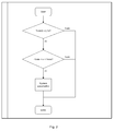
Fig. 2 ein erstes Ablaufdiagramm der Ausführungsform gemäßFig 1 zeigt, -
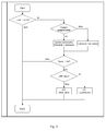
Fig. 3 ein zweites Ablaufdiagramm der Ausführungsform gemäßFig 1 zeigt, -
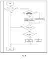
Fig. 4 ein drittes Ablaufdiagramm der Ausführungsform gemäßFig 1 zeigt und -
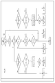
Fig. 5 ein viertes Ablaufdiagramm der Ausführungsform gemäßFig 1 zeigt. -
Fig. 1 zeigt in einer perspektivischen Darstellung einen Rollstuhl mit zwei Laufrädern 10. Jedes Laufrad 10 verfügt über eine Nabe 11, die mittels handelsüblicher Speichen 17 mit einer Felge 18 verbunden ist, auf der ein Reifen 19 aufgezogen ist. Im Inneren der Nabe 11 sind ein Antriebsmotor, der als Elektromotor ausgeführt ist (nicht gezeigt), eine wieder aufladbare Batterie (nicht gezeigt) und eine Steuereinrichtung (nicht gezeigt) angeordnet. - Ein Greifring 12 ist über drei Streben 13 und drei Speichenelemente 14 mit der Nabe 11 verbunden.
- Wenn in den Greifring 12 eine manuelle Kraft eingeleitet wird, wird diese über die Streben 13 und die Speichenelemente 14 direkt auf die Nabe 11 übertragen. Eine Sensoreinrichtung erfasst die Wirkung der Kraft, die auf ein Speichenelement 14 einwirkt. Diese Wirkung ist zum einen eine in dem Speichenelement 14 erzeugte Spannung und zum anderen eine Verformung des Speichenelements. Jeweils mindestens eine dieser Wirkungen wird erfasst und dient als Maß für die in den Greifring 14 eingeleitete Kraft. Entsprechend diesem Maß wird der Antriebsmotor von der Steuerungseinrichtung zur Bereitstellung eines Drehmoments angesteuert. Hierbei können variable oder fest vorprogrammierte Unterstützungsgrade vorgesehen sein.
- Geeignete derartige Sensoreinrichtungen beziehungsweise Sensoren sind beispielsweise in der
EP 0 945 113 A2 offenbart. - Die Steuereinrichtung ist dazu ausgelegt, eine Antirückroll-Funktion (ARF) auszuüben, die rein softwaretechnisch realisiert ist. Es werden hierzu nur Signale und physikalische Größen verarbeitet, die bereits für den Rollstuhlbetrieb ohne diese Funktion vorhanden sind bzw. genutzt werden. Beide Antriebsräder arbeiten hinsichtlich dieser Funktion unabhängig voneinander.
- In einer bevorzugten Ausführungsform arbeitet die Steuereinrichtung als Standardbetriebsart mit einer Drehmomentsteuerung. Dies bedeutet, dass der Antriebsmotor in Abhängigkeit vom gewählten oder durch sonstige Funktionen momentan eingestellten Unterstützungsgrad sowie der manuell in den Greifring 12 eingeleiteten Kraft so angesteuert wird, dass er ein bestimmtes Drehmoment abgibt.
- In einem hierzu alternativ verfügbaren Antirückroll-Betriebsmodus arbeitet die Steuereinrichtung entweder gemäß der vorstehend erläuterten Drehmomentsteuerung oder wechselt bei Bedarf zu einer Drehfrequenzregelung, die die Drehfrequenz des Laufrades regelt, wobei der Sollwert der Drehfrequenz des Laufrades Null ist, was zum Stillstand des Laufrades führt.
- Im Folgenden wird zunächst in Verbindung mit
Fig. 2 das Ausschalten der Steuereinrichtung und damit auch der Antirückroll-Funktion beschrieben. Wird ein im Ablaufdiagramm gemäßFig. 2 als Taste0 bezeichneter Ausschalter länger als 0,1 Sekunde betätigt, erfolgt eine Abfrage, ob die Drehfrequenz des Laufrades größer als -1/min und kleiner als 1/min ist, d.h. ob sich das Rad im Stillstand befindet. Ist dies nicht der Fall, ist ein Ausschalten des Systems nicht möglich. Befindet sich das Laufrad im Stillstand, wird das System bei entsprechender Betätigung der Taste ausgeschaltet. - Das Einschalten des Systems an sich sowie der speziellen Antirückroll-Funktion wird im Folgenden anhand der
Figuren 3 und4 beschrieben. Erstere bezieht sich auf eine Taste1, d.h. eine einen ersten Unterstützungsgrad anwählende Einschalttaste und letztere auf einer Taste2, d.h. eine einen zweiten Unterstützungsgrad anwählende Taste. Es versteht sich, dass auch eine größere Anzahl von Tasten bereitgestellt sein können. Es versteht sich zudem, dass die Unterstützungsgrade einstellbar oder programmierbar sein können. - Wird eine der beiden Einschalttasten, in
Figur 3 als Taste1 und inFigur 4 als Taste2 bezeichnet, länger als 0,1 Sekunde gedrückt, erfolgt zunächst eine Abfrage, ob das System ausgeschaltet ist. Ist dies der Fall, wird das System mit der jeweiligen Fahrstufe aktiviert. Ist das System eingeschaltet, wird die der jeweiligen Taste entsprechende Fahrstufe aktiviert. Die beiden Einschalttasten Taste1 und Taste2 können somit nicht nur zum Einschalten des Systems aus einem ausgeschalteten Zustand, sondern auch zum Umschalten von Fahrstufe 1 auf Fahrstufe 2 beziehungsweise Fahrstufe 2 auf Fahrstufe 1 verwendet werden. - Als nächstes erfolgt eine Abfrage, ob die jeweilige Taste länger als drei Sekunden gedrückt wird. Ist dies nicht der Fall, bleibt das System mit der jeweiligen Fahrstufe aktiviert. Die Steuereinrichtung arbeitet dann in dem Normal-Betriebsmodus mit einer Drehmomentsteuerung.
- Wird die jeweilige Einschalttaste Taste1 oder Taste2 länger als drei Sekunden gedrückt, wird bei aktivierter Antirückroll-Funktion diese ausgeschaltet und bei deaktivierter Antirückrollfunktion diese eingeschaltet. Die Einschalttasten Taste1 und Taste2 können somit sowohl zum Einschalten als auch zum Ausschalten der Antirückroll-Funktion verwendet werden.
- Die Arbeitsweise der Antirückroll-Funktion wird im Folgenden anhand des Flussdiagramms gemäß
Figur 5 erläutert. Der diesbezügliche Programmablauf wird zyklisch wiederholt. - Zunächst findet eine Abfrage statt, ob die Antirückroll-Funktion aktiviert ist. Ist dies der Fall, wird festgestellt, ob eine Kraft in den Greifring eingeleitet wird, wobei nicht nur die Kraft an sich, sondern auch die Richtung der Kraft erfasst wird. Entsprechend dieser Richtung wird bei einer positiv definierten, d.h. in einer ersten Richtung wirkenden Kraft der rechte Teil des Flussdiagramms durchlaufen und bei einer negativ definierten, d.h. in Gegenrichtung zur ersten Richtung gerichteten Kraft der linke Teil des Flussdiagramms durchlaufen. Wird keine Kraft festgestellt, wird der Wert eines Zeitschalters (ARF-Timer) abgefragt. Ist dieser nicht größer 0 Sekunde, wird das durch den Antriebsmotor bereitgestellte Drehmoment M_Rad zeitlinear auf 0 reduziert.
- Ist der Wert des Zeitschalters ARF-Timer größer als 0 Sekunde, findet eine Abfrage statt, ob die Drehzahl des Rades n_Rad kleiner als Null ist und gleichzeitig der Merker NR den Wert 1 hat oder die Drehzahl des Rades n_Rad größer Null ist und gleichzeitig der Merker NL auf 1 gesetzt ist. Sind beide Bedingungen nicht erfüllt, wird der Zyklus beendet und beginnt bei Start von vorne. Ist eine der beiden Bedingungen erfüllt, wird die Drehfrequenzregelung aktiviert und der Soll-Wert der Radfrequenz n_Soll auf 0 gesetzt. Die Bedeutung der beiden letztgenannten Abfragen und der Marker NR und NL werden im Folgenden im Zusammenhang mit dem jeweils linken bzw. rechten Zweig des Ablaufdiagramms gemäß
Fig. 5 erläutert. - Der rechte Zweig des Flussdiagramms gemäß
Fig. 5 wird dann aktiv, wenn bei aktivierter Antirückroll-Funktion am Greifring eine positive manuell eingeleitete Kraft, d.h. eine Kraft F_Greifring größer Null festgestellt wird. In diesem Fall erfolgt eine weitere Abfrage dahingehend, ob die Drehfrequenzregelung aktiv ist. Wie bereits erläutert, kommt im Antirückroll-Betriebsmodus grundsätzlich die Drehmomentsteuerung zum Einsatz. Ist die Drehfrequenzregelung bei einer positiven Kraft nicht aktiv, wird unter Umgehung der nächsten Abfrage und der daraus resultierenden Operation abgefragt, ob die Drehfrequenz des Rades N Rad größer Null ist. Die Werte größer Null im Zusammenhang mit der Drehzahl beziehungsweise Drehfrequenz des Rades und im Zusammenhang mit der am Greifring eingeleiteten manuellen Kraft bezieht sich jeweils darauf, dass sie in gleiche Richtung erfolgen. Wird die letztgenannte Abfrage mit ja beantwortete, d.h. dreht sich das Rad in der gleichen Richtung, in der auch am Greifring eine Kraft eingeleitet wurde, so bleibt weiterhin die Drehmomentsteuerung aktiviert, der Wert des Zeitschalters ARF-Timer wird auf 5 Sekunden gesetzt und der Merker NR auf den Wert 1. - Wird demgegenüber in der obersten Raute des rechten Zweigs des Flussdiagramms gemäß
Fig. 5 festgestellt, dass die Drehfrequenzregelung aktiv ist, erfolgt eine Abfrage dahingehend, ob die Summe der Drehmomente aus dem aus der manuell in das Laufrad eingeleiteten Antriebskraft resultierenden Drehmoment und einem gemäß einem Unterstützungsgrad in Abhängigkeit von der manuell in das Laufrad eingeleiteten Antriebskraft durch den Antriebsmotor bereitstellbaren Drehmoment, ausgedrückt durch den Parameter M_GR(1+x) größer ist als das momentan von dem Antriebsmotor bereitgestellte Drehmoment, welches gemäß der aktivierten Drehmomentsregelung im Zuge dieser Regelung berechnet wird. - Wird diese Abfrage verneint, so bedeutet dies, dass mit der vom Rollstuhlfahrer manuell eingeleiteten Kraft und der durch den Unterstützungsgrad entsprechend hinzukommenden Antriebskraft des Antriebsmotors kein ausreichendes Drehmoment erzeugt würde, dass größer ist als dasjenige Drehmoment, was momentan durch die Drehfrequenzregelung bereitgestellt wird. Würde die Drehfrequenzregelung daher deaktiviert werden, würde dies zu einer unerwünschten Richtungsumkehr führen. Die Drehfrequenzregelung bleibt daher in diesem Fall aktiv und es erfolgt wiederum die Abfrage dahingehend, ob eine Drehung des Rades in der ersten Richtung vorliegt, d.h. die Drehfrequenz N-Rad größer als Null ist. Ist dies nicht der Fall, wird der Merker NR auf 0 gesetzt. Ist dies der Fall, wird der Wert des Zeitschalters ARF-Timer auf 5 Sekunden gesetzt und der Merker NR auf den Wert 1.
- Wird demgegenüber bei der zuvor erläuterten Abfrage der Werte des hypothetisch aufsummierten Drehmoments mit dem aktuellen Drehmoment des Antriebmotors gemäß Drehfrequenzregelung festgestellt, dass dieser hypothetische Summenwert größer ist, so bedeutet dies, dass das Rad bei aktivierter Drehmomentsteuerung in Wunschrichtung drehen würde. In diesem Fall wird die Drehfrequenzregelung deaktiviert und die Drehmomentsteuerung aktiviert. Danach findet erneut die die Drehfrequenz des Rades betreffende Abfrage statt.
- Der linke Zweig des Flussdiagramms gemäß
Fig. 5 verläuft in analoger Weise, wobei eine negative Kraft und eine negative Drehfrequenz des Antriebsrades bedeuten, dass Kraft und Drehung des Antriebsrades in gleiche Richtung verlaufen. Diese können beispielsweise als rechtsdrehend im Uhrzeigersinn oder linksdrehend im Gegenuhrzeigersinn definiert sein. - Entsprechend wird bei Rechtsdrehung, das heißt bei Werten größer Null der Merker mit NR entsprechend dem rechten Zweig des Flussdiagramms gemäß
Fig. 5 und bei Linksdrehung, das heißt bei Werten kleiner Null der Merker mit NL gemäß dem linken Zweig des Flussdiagramms gemäßFig. 5 bezeichnet. - In dem Ablaufdiagramm gemäß
Fig. 5 wird der Merker NR auf den Wert 1 gesetzt, wenn bei einer positiven Kraft am Greifring eine positive Drehfrequenz des Rades vorliegt. Andernfalls wird der Merker NR auf 0 gesetzt. Entsprechend wird der Merker NL auf 1 gesetzt, wenn bei einer negativen Kraft am Greifring eine negative Drehfrequenz des Rades vorliegt. - Die beiden unteren Rauten im zentralen Zweig des Flussdiagramms gemäß
Fig. 5 betreffen Fälle, in denen keine Kraft in den Greifring eingeleitet wird. Durch die Bereitstellung des Merkers wird jedoch die Sollrichtung der Raddrehung gemäß vorheriger Zyklen erkannt. Bei der untersten Raute im zentralen Zweig des Ablaufdiagramms gemäßFig. 5 findet die Abfrage statt, ob die Drehfrequenz des Rades größer Null ist und gleichzeitig der Merker NL den Wert 1 hat, was bedeuten würde, dass bei negativer Kraft eine negative Drehfrequenz des Rades vorlag. In diesem Fall würden somit die Soll-Richtung der Drehfrequenz und die Ist-Richtung auseinander fallen. Entsprechend wird bei Bejahung der Abfrage die Drehfrequenzregelung aktiviert. - Bezugszeichen:
- 10
- Laufräder
- 11
- Nabe
- 12
- Greifring
- 13
- Streben
- 14
- Speichenelemente
- 17
- Speichen
- 18
- Felge
- 19
- Reifen
Claims (15)
- Hilfsantriebsvorrichtung für einen Rollstuhl
mit einem Antriebsmotor,
mit einem Laufrad,
mit einer Sensoreinrichtung, die dazu ausgelegt ist, eine manuell in das Laufrad (10) eingeleitete Antriebskraft zu erfassen, und
mit einer Steuereinrichtung, die dazu ausgelegt ist, den Antriebsmotor zum Antrieb des Laufrades (10) gemäß einem Unterstützungsgrad in Abhängigkeit von der manuell in das Laufrad (10) eingeleiteten Antriebskraft anzusteuern,
dadurch gekennzeichnet,
dass die Steuereinrichtung einen Antirückroll-Betriebsmodus aufweist, in dem sie dazu ausgelegt ist, den Antriebsmotor so anzusteuern, dass ein unbeabsichtigtes Rollen des Laufrades (10) vermieden wird. - Hilfsantriebsvorrichtung nach Anspruch 1, dadurch gekennzeichnet, dass die Steuereinrichtung dazu ausgelegt ist, in einem Normal-Betriebsmodus zu arbeiten, in dem das Vermeiden eines unbeabsichtigten Rollens des Laufrades (10) außer Kraft gesetzt ist, und alternativ in dem Antirückroll-Betriebsmodus zu arbeiten, um den Antriebsmotor bei Bedarf so anzusteuern, dass ein unbeabsichtigtes Rollen des Laufrades (10) vermieden wird.
- Hilfsantriebsvorrichtung nach Anspruch 2, dadurch gekennzeichnet, dass der Normal-Betriebsmodus eine Drehmomentsteuerung umfasst, die bewirkt, dass der Antriebsmotor zum Antrieb des Laufrades (10) in Abhängigkeit von der manuell in das Laufrad (10) eingeleiteten Antriebskraft angesteuert wird.
- Hilfsantriebsvorrichtung nach Anspruch 1, 2 oder 3, dadurch gekennzeichnet, dass der Antirückroll-Betriebsmodus eine Drehfrequenzregelung umfasst, die die Drehfrequenz des Laufrades (10) regelt.
- Hilfsantriebsvorrichtung nach Anspruch 4, dadurch gekennzeichnet, dass in dem Antirückroll-Betriebsmodus alternativ die Drehmomentsteuerung oder die Drehfrequenzregelung zum Einsatz kommt.
- Hilfsantriebsvorrichtung nach Anspruch 5, dadurch gekennzeichnet, dass die Steuereinrichtung dazu ausgelegt ist, einen Wechsel zwischen Drehmomentsteuerung und Drehfrequenzregelung in Abhängigkeit von Betriebsparametern zu bewirken.
- Hilfsantriebsvorrichtung nach Anspruch 6, dadurch gekennzeichnet, dass die Betriebsparameter einen oder mehrere Parameter aufweisen aus der Gruppe Drehfrequenz des Laufrades, Drehrichtung des Laufrades, Größe der manuell in das Laufrad (10) eingeleiteten Antriebskraft, Richtung der manuell in das Laufrad (10) eingeleiteten Antriebskraft, Summe des aus der manuell in das Laufrad (10) eingeleiteten Antriebskraft resultierenden Drehmoments und eines gemäß einem Unterstützungsgrad in Abhängigkeit von der manuell in das Laufrad (10) eingeleiteten Antriebskraft durch den Antriebsmotor bereitstellbaren Drehmoments, das durch den Antriebsmotor aktuell bereitgestellte Drehmoment, Wert eines Zeitschalters.
- Hilfsantriebsvorrichtung nach einem der vorstehenden Ansprüche, dadurch gekennzeichnet, dass der Antirückroll-Betriebsmodus manuell einschaltbar und/ oder ausschaltbar ist.
- Hilfsantriebsvorrichtung nach Anspruch 8, dadurch gekennzeichnet, dass mehrere Unterstützungsgrad-Schalter vorgesehen sind, mit denen unterschiedliche Unterstützungsgrade vorwählbar sind, und dass der Antirückroll-Betriebsmodus über einen oder jeden der Unterstützungsgrad-Schalter einschaltbar und/oder ausschaltbar ist.
- Hilfsantriebsvorrichtung nach Anspruch 9, dadurch gekennzeichnet, dass sich die Steuereinrichtung beim Einschalten im Normal-Betriebsmodus befindet.
- Hilfsantriebsvorrichtung nach Anspruch 9, dadurch gekennzeichnet, dass sich die Steuereinrichtung beim Einschalten in demjenigen Betriebsmodus befindet, in dem sie sich beim vorherigen Ausschalten befand.
- Hilfsantriebsvorrichtung nach einem der vorstehenden Ansprüche, gekennzeichnet durch einen Greifring (12), über den Kraft manuell in das Laufrad (10) einleitbar ist.
- Hilfsantriebsvorrichtung nach einem der vorstehenden Ansprüche, dadurch gekennzeichnet, dass der Antriebsmotor als Elektromotor ausgeführt ist.
- Hilfsantriebsvorrichtung nach Anspruch 13, dadurch gekennzeichnet, dass der Antriebsmotor zusammen mit einer wiederaufladbaren Batterie und der Steuereinrichtung in der Nabe (11) des Laufrades (10) angeordnet ist.
- Rollstuhl mit einer Hilfsantriebsvorrichtung nach einem der Ansprüche 1 bis 14.
Priority Applications (1)
| Application Number | Priority Date | Filing Date | Title |
|---|---|---|---|
| PL09161803T PL2151221T3 (pl) | 2008-08-08 | 2009-06-03 | Pomocnicze urządzenie napędowe dla wózka inwalidzkiego i wózek inwalidzki z pomocniczym urządzeniem napędowym |
Applications Claiming Priority (1)
| Application Number | Priority Date | Filing Date | Title |
|---|---|---|---|
| DE102008002993A DE102008002993B3 (de) | 2008-08-08 | 2008-08-08 | Hilfsantriebsvorrichtung für einen Rollstuhl und Rollstuhl mit Hilfsantriebsvorrichtung |
Publications (3)
| Publication Number | Publication Date |
|---|---|
| EP2151221A2 true EP2151221A2 (de) | 2010-02-10 |
| EP2151221A3 EP2151221A3 (de) | 2011-12-21 |
| EP2151221B1 EP2151221B1 (de) | 2013-09-11 |
Family
ID=41112215
Family Applications (1)
| Application Number | Title | Priority Date | Filing Date |
|---|---|---|---|
| EP09161803.3A Active EP2151221B1 (de) | 2008-08-08 | 2009-06-03 | Hilfsantriebsvorrichtung für einen Rollstuhl und Rollstuhl mit Hilfsantriebsvorrichtung |
Country Status (10)
| Country | Link |
|---|---|
| US (1) | US7840327B2 (de) |
| EP (1) | EP2151221B1 (de) |
| JP (1) | JP2010057901A (de) |
| AU (1) | AU2009202576A1 (de) |
| CA (1) | CA2674328C (de) |
| DE (2) | DE102008002993B3 (de) |
| DK (1) | DK2151221T3 (de) |
| ES (1) | ES2438816T3 (de) |
| NZ (1) | NZ577780A (de) |
| PL (1) | PL2151221T3 (de) |
Cited By (1)
| Publication number | Priority date | Publication date | Assignee | Title |
|---|---|---|---|---|
| EP2649973A1 (de) * | 2012-04-12 | 2013-10-16 | AAT Alber Antriebstechnik GmbH | Hilfsantriebsvorrichtung für Rollstühle |
Families Citing this family (19)
| Publication number | Priority date | Publication date | Assignee | Title |
|---|---|---|---|---|
| DE202010017965U1 (de) * | 2010-09-22 | 2013-05-02 | Ulrich Alber Gmbh | Hilfsantriebsvorrichtung, Rollstuhl und Vorrichtung zur Ermittlung von physischen Leistungsdaten eines Rollstuhlfahrers |
| DE102010037705B4 (de) * | 2010-09-22 | 2014-04-24 | Ulrich Alber Gmbh | Hilfsantriebsvorrichtung, Rollstuhl und Verfahren zur Ermittlung der manuellen Antriebskraft eines Rollstuhlfahrers |
| US8496080B2 (en) * | 2010-09-30 | 2013-07-30 | National Taiwan University | Wheel driven mechanism |
| US9398990B2 (en) | 2011-07-06 | 2016-07-26 | W Mark Richter | Motion-based power assist system for wheelchairs |
| US20130257010A1 (en) * | 2011-08-30 | 2013-10-03 | Melvin G. Hector, JR. | Automatic Braking Device and Method |
| CH706683A2 (de) | 2012-06-27 | 2013-12-31 | Hasan Hueseyin Isik | Rollstuhl. |
| US9144525B2 (en) | 2013-03-14 | 2015-09-29 | Max Mobility, Llc. | Motion assistance system for wheelchairs |
| US9498395B2 (en) | 2014-04-16 | 2016-11-22 | Stephen C. Golden, JR. | Joint movement detection device and system for coordinating motor output with manual wheelchair propulsion |
| US9795524B2 (en) | 2015-02-24 | 2017-10-24 | Max Mobility, Llc | Assistive driving system for a wheelchair |
| DE102016204766A1 (de) | 2016-03-22 | 2017-09-28 | Robert Bosch Gmbh | Verfahren und Vorrichtung zur prädiktiven Ansteuerung eines Elektromotors zur Risikoreduzierung des Umkippens eines Rollstuhls |
| DE102016204762A1 (de) | 2016-03-22 | 2017-10-12 | Robert Bosch Gmbh | Verfahren und Vorrichtung zur Ansteuerung eines Elektromotors für die Balancierunterstützung eines Rollstuhls |
| DE102016204763A1 (de) | 2016-03-22 | 2017-09-28 | Robert Bosch Gmbh | Verfahren und Vorrichtung zur Ansteuerung eines Elektromotors für eine erweiterte Balancierunterstützung eines Rollstuhls |
| DE102016204765A1 (de) | 2016-03-22 | 2017-09-28 | Robert Bosch Gmbh | Verfahren und Vorrichtung zur Ansteuerung eines Elektromotors zur Reduzierung des Risikos eines Umkippens eines Rollstuhls |
| CN106963570B (zh) * | 2017-02-27 | 2019-01-15 | 东莞产权交易中心 | 一种老年人代步车 |
| DE102017111129B4 (de) * | 2017-05-22 | 2024-07-11 | Otto Bock Mobility Solutions Gmbh | Rollstuhl mit wenigstens einem elektrischen Hilfsantrieb |
| DE102017111127A1 (de) * | 2017-05-22 | 2018-11-22 | Otto Bock Mobility Solutions Gmbh | Rollstuhl mit wenigstens einem elektrischen Hilfsantrieb |
| WO2019075081A1 (en) | 2017-10-12 | 2019-04-18 | The Center for Discovery, Inc. | DRIVE ASSEMBLY FOR A MANUALLY OPERATING WHEELCHAIR AND METHODS OF USE |
| US10167051B1 (en) | 2017-12-12 | 2019-01-01 | Max Mobility, Llc | Assistive driving system for a wheelchair and method for controlling assistive driving system |
| JP7631043B2 (ja) * | 2021-03-10 | 2025-02-18 | ヤマハ発動機株式会社 | 電動アシスト車椅子、駆動ユニット、制御方法およびコンピュータプログラム |
Citations (1)
| Publication number | Priority date | Publication date | Assignee | Title |
|---|---|---|---|---|
| EP0945113A2 (de) | 1998-03-21 | 1999-09-29 | Ulrich Alber GmbH | Hilfsantriebsvorrichtung für Selbstfahrer-Rollstühle |
Family Cites Families (15)
| Publication number | Priority date | Publication date | Assignee | Title |
|---|---|---|---|---|
| US5376869A (en) * | 1993-02-11 | 1994-12-27 | General Electric Company | Electric vehicle drive train with rollback detection and compensation |
| JP3703554B2 (ja) | 1996-02-14 | 2005-10-05 | ヤマハ発動機株式会社 | 補助動力付き車椅子 |
| US6112837A (en) | 1996-09-30 | 2000-09-05 | Yamaha Hatsudoki Kabushiki Kaisha | Manually operated, motor assisted wheelchair |
| JP3957101B2 (ja) * | 1997-04-01 | 2007-08-15 | ナブテスコ株式会社 | 電動車両の制御装置 |
| JPH10314232A (ja) * | 1997-05-19 | 1998-12-02 | Yamaha Motor Co Ltd | 補助動力式車椅子 |
| JP4521893B2 (ja) | 1998-05-18 | 2010-08-11 | ヤマハ発動機株式会社 | 補助動力式車椅子 |
| JP2000152425A (ja) * | 1998-11-13 | 2000-05-30 | Nabco Ltd | 電動車両の走行制御装置 |
| US6560515B2 (en) * | 2000-10-04 | 2003-05-06 | Nabco, Ltd. | Control apparatus for electric vehicle |
| US7316298B2 (en) * | 2002-04-29 | 2008-01-08 | The United States Of America As Represented By The Secretary Of The Army | Wheelchair safety brake assembly |
| ATE449987T1 (de) * | 2002-06-11 | 2009-12-15 | Deka Products Lp | Von menschen/elektrisch angetriebenes hybridfahrzeug |
| US6916032B2 (en) * | 2002-08-05 | 2005-07-12 | J.T. Labs, Ltd. | Manually-propelled vehicle and related systems |
| WO2004022371A2 (en) * | 2002-09-04 | 2004-03-18 | Air Movement Technologies, Inc | Automatic wheelchair brake system and wheelchair including same |
| US7870917B2 (en) * | 2004-10-25 | 2011-01-18 | Sanyo Electric Co., Ltd. | Drive device for electrically movable vehicles and electric wheelchair having same |
| JP4408789B2 (ja) * | 2004-10-25 | 2010-02-03 | 三洋電機株式会社 | 電動車両用駆動装置及びこれを具えた電動車椅子 |
| WO2007018034A1 (ja) * | 2005-08-05 | 2007-02-15 | Yamaha Hatsudoki Kabushiki Kaisha | 電動式小型車両の走行制御装置 |
-
2008
- 2008-08-08 DE DE102008002993A patent/DE102008002993B3/de not_active Expired - Fee Related
- 2008-08-08 DE DE202008017474U patent/DE202008017474U1/de not_active Expired - Lifetime
-
2009
- 2009-06-03 EP EP09161803.3A patent/EP2151221B1/de active Active
- 2009-06-03 PL PL09161803T patent/PL2151221T3/pl unknown
- 2009-06-03 ES ES09161803.3T patent/ES2438816T3/es active Active
- 2009-06-03 DK DK09161803.3T patent/DK2151221T3/da active
- 2009-06-18 NZ NZ577780A patent/NZ577780A/en not_active IP Right Cessation
- 2009-06-26 AU AU2009202576A patent/AU2009202576A1/en not_active Abandoned
- 2009-07-17 JP JP2009168501A patent/JP2010057901A/ja active Pending
- 2009-07-22 CA CA2674328A patent/CA2674328C/en not_active Expired - Fee Related
- 2009-07-30 US US12/512,260 patent/US7840327B2/en not_active Expired - Fee Related
Patent Citations (1)
| Publication number | Priority date | Publication date | Assignee | Title |
|---|---|---|---|---|
| EP0945113A2 (de) | 1998-03-21 | 1999-09-29 | Ulrich Alber GmbH | Hilfsantriebsvorrichtung für Selbstfahrer-Rollstühle |
Cited By (1)
| Publication number | Priority date | Publication date | Assignee | Title |
|---|---|---|---|---|
| EP2649973A1 (de) * | 2012-04-12 | 2013-10-16 | AAT Alber Antriebstechnik GmbH | Hilfsantriebsvorrichtung für Rollstühle |
Also Published As
| Publication number | Publication date |
|---|---|
| PL2151221T3 (pl) | 2014-03-31 |
| NZ577780A (en) | 2010-09-30 |
| DE202008017474U1 (de) | 2009-09-24 |
| ES2438816T3 (es) | 2014-01-20 |
| CA2674328A1 (en) | 2010-02-08 |
| EP2151221A3 (de) | 2011-12-21 |
| CA2674328C (en) | 2012-05-29 |
| EP2151221B1 (de) | 2013-09-11 |
| DK2151221T3 (da) | 2014-01-06 |
| DE102008002993B3 (de) | 2009-11-05 |
| US20100036543A1 (en) | 2010-02-11 |
| JP2010057901A (ja) | 2010-03-18 |
| US7840327B2 (en) | 2010-11-23 |
| AU2009202576A1 (en) | 2010-02-25 |
Similar Documents
| Publication | Publication Date | Title |
|---|---|---|
| EP2151221B1 (de) | Hilfsantriebsvorrichtung für einen Rollstuhl und Rollstuhl mit Hilfsantriebsvorrichtung | |
| DE69106143T2 (de) | Einrichtung und verfahren zum bedienen eines fahrzeugantriebs und dessen anordnung. | |
| DE102012002318A1 (de) | Verfahren zum Betreiben eines Kraftwagens und Kraftwagen mit einem Fahrerassistenzsystem | |
| DE102012002307A1 (de) | Kraftwagen mit einer Fahrerassistenzeinrichtung und Verfahren zum Betreiben eines Kraftwagens | |
| DE112017004674T5 (de) | Fahrzeugsteuersystem, fahrzeugsteuerverfahren und elektrisches servolenksystem | |
| WO2019012060A1 (de) | Kinderwagengestell und kinderwagen | |
| DE102012215057A1 (de) | Fahrerassistenzsystem | |
| EP2861448B1 (de) | Bedienungssystem für fahrerassistenzsysteme eines kraftwagens und kraftwagen mit einem solchen bedienungssystem | |
| EP3492330B1 (de) | Verfahren zum betreiben eines kraftfahrzeugs sowie entsprechendes kraftfahrzeug | |
| EP2953837B1 (de) | Lenksystem für ein fahrzeug sowie mehrwegetransportfahrzeug | |
| WO2018206557A1 (de) | Manuelles und individuelles konfigurieren eines rekuperationsverhaltens | |
| DE102019202003A1 (de) | Verfahren zur Steuerung eines Lenksystems für ein Kraftfahrzeug und Lenksystem für ein Kraftfahrzeug zur Durchführung des Verfahrens | |
| DE102013103757B4 (de) | Verfahren und Vorrichtung zum Bedienen eines mobilen Operationstischs | |
| AT522588B1 (de) | Verfahren zur korrektur einer gierrate | |
| DE102016005938B4 (de) | Sicherheitsbetrieb für ein Steer-By-Wire-Lenksystem | |
| DE102004035024B4 (de) | Lenkvorrichtung mit variablem Übertragungsverhältnis | |
| WO2013144063A1 (de) | Geschwindigkeitsregelsystem mit einem berührungssensitiven bedienelement | |
| WO2012156085A1 (de) | Verfahren einer elektrohydraulischen hubwerksregelung und bedieneinheit für eine elektrohydraulische hubwerksregelung | |
| EP0346592A1 (de) | Antriebsschlupfregel- und Fahrgeschwindigkeitsbegrenzungs-Einrichtung | |
| DE102013207539A1 (de) | Geschwindigkeitsregelsystem für Kraftfahrzeuge | |
| EP2082944B1 (de) | Verfahren zum Erzeugen eins Rückführdrehmoment-Signals | |
| DE10325925A1 (de) | Verfahren und Vorrichtung zur Regelung der Fahrgeschwindigkeit eines Kraftfahrzeugs | |
| WO2005120931A1 (de) | Verfahren zum betrieb eines hilfskraftlenksystems und hilfskraftlenksystem | |
| DE102012018327B4 (de) | Verfahren zur Steuerung des Antriebssystems eines Kraftfahrzeugs und Kraftfahrzeug | |
| WO2016110313A1 (de) | Verfahren zur ansteuerung von e-motoren bei seriellen hybridfahrzeugen mit mindestens zwei separat angetriebenen achsen |
Legal Events
| Date | Code | Title | Description |
|---|---|---|---|
| PUAI | Public reference made under article 153(3) epc to a published international application that has entered the european phase |
Free format text: ORIGINAL CODE: 0009012 |
|
| AK | Designated contracting states |
Kind code of ref document: A2 Designated state(s): AT BE BG CH CY CZ DE DK EE ES FI FR GB GR HR HU IE IS IT LI LT LU LV MC MK MT NL NO PL PT RO SE SI SK TR |
|
| AX | Request for extension of the european patent |
Extension state: AL BA RS |
|
| PUAL | Search report despatched |
Free format text: ORIGINAL CODE: 0009013 |
|
| AK | Designated contracting states |
Kind code of ref document: A3 Designated state(s): AT BE BG CH CY CZ DE DK EE ES FI FR GB GR HR HU IE IS IT LI LT LU LV MC MK MT NL NO PL PT RO SE SI SK TR |
|
| AX | Request for extension of the european patent |
Extension state: AL BA RS |
|
| RIC1 | Information provided on ipc code assigned before grant |
Ipc: A61G 5/10 20060101ALN20111116BHEP Ipc: A61G 5/04 20060101AFI20111116BHEP |
|
| 17P | Request for examination filed |
Effective date: 20120601 |
|
| 17Q | First examination report despatched |
Effective date: 20120807 |
|
| RIC1 | Information provided on ipc code assigned before grant |
Ipc: A61G 5/10 20060101ALN20130213BHEP Ipc: A61G 5/04 20130101AFI20130213BHEP |
|
| RIC1 | Information provided on ipc code assigned before grant |
Ipc: A61G 5/10 20060101ALN20130215BHEP Ipc: A61G 5/04 20130101AFI20130215BHEP |
|
| GRAP | Despatch of communication of intention to grant a patent |
Free format text: ORIGINAL CODE: EPIDOSNIGR1 |
|
| INTG | Intention to grant announced |
Effective date: 20130404 |
|
| GRAS | Grant fee paid |
Free format text: ORIGINAL CODE: EPIDOSNIGR3 |
|
| GRAA | (expected) grant |
Free format text: ORIGINAL CODE: 0009210 |
|
| AK | Designated contracting states |
Kind code of ref document: B1 Designated state(s): AT BE BG CH CY CZ DE DK EE ES FI FR GB GR HR HU IE IS IT LI LT LU LV MC MK MT NL NO PL PT RO SE SI SK TR |
|
| REG | Reference to a national code |
Ref country code: GB Ref legal event code: FG4D Free format text: NOT ENGLISH |
|
| REG | Reference to a national code |
Ref country code: CH Ref legal event code: EP |
|
| REG | Reference to a national code |
Ref country code: AT Ref legal event code: REF Ref document number: 631205 Country of ref document: AT Kind code of ref document: T Effective date: 20130915 |
|
| REG | Reference to a national code |
Ref country code: IE Ref legal event code: FG4D Free format text: LANGUAGE OF EP DOCUMENT: GERMAN |
|
| REG | Reference to a national code |
Ref country code: DE Ref legal event code: R096 Ref document number: 502009007981 Country of ref document: DE Effective date: 20131107 |
|
| REG | Reference to a national code |
Ref country code: CH Ref legal event code: NV Representative=s name: LATSCHA SCHOELLHORN PARTNER AG, CH |
|
| REG | Reference to a national code |
Ref country code: SE Ref legal event code: TRGR |
|
| REG | Reference to a national code |
Ref country code: NL Ref legal event code: T3 |
|
| REG | Reference to a national code |
Ref country code: DK Ref legal event code: T3 Effective date: 20131216 |
|
| REG | Reference to a national code |
Ref country code: ES Ref legal event code: FG2A Ref document number: 2438816 Country of ref document: ES Kind code of ref document: T3 Effective date: 20140120 |
|
| PG25 | Lapsed in a contracting state [announced via postgrant information from national office to epo] |
Ref country code: HR Free format text: LAPSE BECAUSE OF FAILURE TO SUBMIT A TRANSLATION OF THE DESCRIPTION OR TO PAY THE FEE WITHIN THE PRESCRIBED TIME-LIMIT Effective date: 20130911 Ref country code: CY Free format text: LAPSE BECAUSE OF FAILURE TO SUBMIT A TRANSLATION OF THE DESCRIPTION OR TO PAY THE FEE WITHIN THE PRESCRIBED TIME-LIMIT Effective date: 20130821 Ref country code: LT Free format text: LAPSE BECAUSE OF FAILURE TO SUBMIT A TRANSLATION OF THE DESCRIPTION OR TO PAY THE FEE WITHIN THE PRESCRIBED TIME-LIMIT Effective date: 20130911 |
|
| REG | Reference to a national code |
Ref country code: NO Ref legal event code: T2 Effective date: 20130911 |
|
| REG | Reference to a national code |
Ref country code: LT Ref legal event code: MG4D |
|
| PG25 | Lapsed in a contracting state [announced via postgrant information from national office to epo] |
Ref country code: SI Free format text: LAPSE BECAUSE OF FAILURE TO SUBMIT A TRANSLATION OF THE DESCRIPTION OR TO PAY THE FEE WITHIN THE PRESCRIBED TIME-LIMIT Effective date: 20130911 Ref country code: LV Free format text: LAPSE BECAUSE OF FAILURE TO SUBMIT A TRANSLATION OF THE DESCRIPTION OR TO PAY THE FEE WITHIN THE PRESCRIBED TIME-LIMIT Effective date: 20130911 Ref country code: GR Free format text: LAPSE BECAUSE OF FAILURE TO SUBMIT A TRANSLATION OF THE DESCRIPTION OR TO PAY THE FEE WITHIN THE PRESCRIBED TIME-LIMIT Effective date: 20131212 |
|
| PG25 | Lapsed in a contracting state [announced via postgrant information from national office to epo] |
Ref country code: CY Free format text: LAPSE BECAUSE OF FAILURE TO SUBMIT A TRANSLATION OF THE DESCRIPTION OR TO PAY THE FEE WITHIN THE PRESCRIBED TIME-LIMIT Effective date: 20130911 |
|
| PG25 | Lapsed in a contracting state [announced via postgrant information from national office to epo] |
Ref country code: EE Free format text: LAPSE BECAUSE OF FAILURE TO SUBMIT A TRANSLATION OF THE DESCRIPTION OR TO PAY THE FEE WITHIN THE PRESCRIBED TIME-LIMIT Effective date: 20130911 Ref country code: SK Free format text: LAPSE BECAUSE OF FAILURE TO SUBMIT A TRANSLATION OF THE DESCRIPTION OR TO PAY THE FEE WITHIN THE PRESCRIBED TIME-LIMIT Effective date: 20130911 Ref country code: RO Free format text: LAPSE BECAUSE OF FAILURE TO SUBMIT A TRANSLATION OF THE DESCRIPTION OR TO PAY THE FEE WITHIN THE PRESCRIBED TIME-LIMIT Effective date: 20130911 Ref country code: CZ Free format text: LAPSE BECAUSE OF FAILURE TO SUBMIT A TRANSLATION OF THE DESCRIPTION OR TO PAY THE FEE WITHIN THE PRESCRIBED TIME-LIMIT Effective date: 20130911 Ref country code: IS Free format text: LAPSE BECAUSE OF FAILURE TO SUBMIT A TRANSLATION OF THE DESCRIPTION OR TO PAY THE FEE WITHIN THE PRESCRIBED TIME-LIMIT Effective date: 20140111 |
|
| REG | Reference to a national code |
Ref country code: DE Ref legal event code: R097 Ref document number: 502009007981 Country of ref document: DE |
|
| PG25 | Lapsed in a contracting state [announced via postgrant information from national office to epo] |
Ref country code: PT Free format text: LAPSE BECAUSE OF FAILURE TO SUBMIT A TRANSLATION OF THE DESCRIPTION OR TO PAY THE FEE WITHIN THE PRESCRIBED TIME-LIMIT Effective date: 20140113 |
|
| PLBE | No opposition filed within time limit |
Free format text: ORIGINAL CODE: 0009261 |
|
| STAA | Information on the status of an ep patent application or granted ep patent |
Free format text: STATUS: NO OPPOSITION FILED WITHIN TIME LIMIT |
|
| REG | Reference to a national code |
Ref country code: DE Ref legal event code: R082 Ref document number: 502009007981 Country of ref document: DE Representative=s name: BITTNER & PARTNER, DE |
|
| 26N | No opposition filed |
Effective date: 20140612 |
|
| REG | Reference to a national code |
Ref country code: CH Ref legal event code: PCAR Free format text: NEW ADDRESS: AUSTRASSE 24, 4051 BASEL (CH) |
|
| REG | Reference to a national code |
Ref country code: DE Ref legal event code: R081 Ref document number: 502009007981 Country of ref document: DE Owner name: ALBER GMBH, DE Free format text: FORMER OWNER: ULRICH ALBER GMBH, 72461 ALBSTADT, DE Effective date: 20140811 Ref country code: DE Ref legal event code: R082 Ref document number: 502009007981 Country of ref document: DE Representative=s name: STAUDT IP LAW, DE Effective date: 20140811 Ref country code: DE Ref legal event code: R082 Ref document number: 502009007981 Country of ref document: DE Representative=s name: BITTNER & PARTNER RECHTS- UND PATENTANWAELTE, DE Effective date: 20140811 |
|
| REG | Reference to a national code |
Ref country code: DE Ref legal event code: R097 Ref document number: 502009007981 Country of ref document: DE Effective date: 20140612 |
|
| PG25 | Lapsed in a contracting state [announced via postgrant information from national office to epo] |
Ref country code: MC Free format text: LAPSE BECAUSE OF FAILURE TO SUBMIT A TRANSLATION OF THE DESCRIPTION OR TO PAY THE FEE WITHIN THE PRESCRIBED TIME-LIMIT Effective date: 20130911 |
|
| REG | Reference to a national code |
Ref country code: FR Ref legal event code: PLFP Year of fee payment: 7 |
|
| REG | Reference to a national code |
Ref country code: DE Ref legal event code: R082 Ref document number: 502009007981 Country of ref document: DE Representative=s name: STAUDT IP LAW, DE |
|
| PG25 | Lapsed in a contracting state [announced via postgrant information from national office to epo] |
Ref country code: MT Free format text: LAPSE BECAUSE OF FAILURE TO SUBMIT A TRANSLATION OF THE DESCRIPTION OR TO PAY THE FEE WITHIN THE PRESCRIBED TIME-LIMIT Effective date: 20130911 |
|
| REG | Reference to a national code |
Ref country code: FR Ref legal event code: PLFP Year of fee payment: 8 |
|
| PG25 | Lapsed in a contracting state [announced via postgrant information from national office to epo] |
Ref country code: BG Free format text: LAPSE BECAUSE OF FAILURE TO SUBMIT A TRANSLATION OF THE DESCRIPTION OR TO PAY THE FEE WITHIN THE PRESCRIBED TIME-LIMIT Effective date: 20130911 |
|
| PG25 | Lapsed in a contracting state [announced via postgrant information from national office to epo] |
Ref country code: TR Free format text: LAPSE BECAUSE OF FAILURE TO SUBMIT A TRANSLATION OF THE DESCRIPTION OR TO PAY THE FEE WITHIN THE PRESCRIBED TIME-LIMIT Effective date: 20130911 Ref country code: HU Free format text: LAPSE BECAUSE OF FAILURE TO SUBMIT A TRANSLATION OF THE DESCRIPTION OR TO PAY THE FEE WITHIN THE PRESCRIBED TIME-LIMIT; INVALID AB INITIO Effective date: 20090603 |
|
| REG | Reference to a national code |
Ref country code: FR Ref legal event code: PLFP Year of fee payment: 9 |
|
| REG | Reference to a national code |
Ref country code: FR Ref legal event code: PLFP Year of fee payment: 10 |
|
| PG25 | Lapsed in a contracting state [announced via postgrant information from national office to epo] |
Ref country code: MK Free format text: LAPSE BECAUSE OF FAILURE TO SUBMIT A TRANSLATION OF THE DESCRIPTION OR TO PAY THE FEE WITHIN THE PRESCRIBED TIME-LIMIT Effective date: 20130911 |
|
| REG | Reference to a national code |
Ref country code: CH Ref legal event code: PCAR Free format text: NEW ADDRESS: GRELLINGERSTRASSE 60, 4052 BASEL (CH) |
|
| PGFP | Annual fee paid to national office [announced via postgrant information from national office to epo] |
Ref country code: ES Payment date: 20190604 Year of fee payment: 14 Ref country code: IT Payment date: 20190619 Year of fee payment: 11 Ref country code: NO Payment date: 20190620 Year of fee payment: 11 Ref country code: LU Payment date: 20190619 Year of fee payment: 11 Ref country code: NL Payment date: 20190619 Year of fee payment: 11 Ref country code: IE Payment date: 20190621 Year of fee payment: 11 Ref country code: FI Payment date: 20190618 Year of fee payment: 11 Ref country code: PL Payment date: 20190521 Year of fee payment: 11 |
|
| PGFP | Annual fee paid to national office [announced via postgrant information from national office to epo] |
Ref country code: SE Payment date: 20190624 Year of fee payment: 11 Ref country code: BE Payment date: 20190619 Year of fee payment: 11 Ref country code: FR Payment date: 20190625 Year of fee payment: 11 |
|
| PGFP | Annual fee paid to national office [announced via postgrant information from national office to epo] |
Ref country code: CH Payment date: 20190624 Year of fee payment: 11 |
|
| PGFP | Annual fee paid to national office [announced via postgrant information from national office to epo] |
Ref country code: GB Payment date: 20190624 Year of fee payment: 11 Ref country code: AT Payment date: 20190618 Year of fee payment: 11 |
|
| REG | Reference to a national code |
Ref country code: FI Ref legal event code: MAE |
|
| REG | Reference to a national code |
Ref country code: DK Ref legal event code: EBP Effective date: 20200630 Ref country code: NO Ref legal event code: MMEP |
|
| PG25 | Lapsed in a contracting state [announced via postgrant information from national office to epo] |
Ref country code: FI Free format text: LAPSE BECAUSE OF NON-PAYMENT OF DUE FEES Effective date: 20200603 |
|
| REG | Reference to a national code |
Ref country code: CH Ref legal event code: PL |
|
| REG | Reference to a national code |
Ref country code: NL Ref legal event code: MM Effective date: 20200701 |
|
| REG | Reference to a national code |
Ref country code: AT Ref legal event code: MM01 Ref document number: 631205 Country of ref document: AT Kind code of ref document: T Effective date: 20200603 |
|
| GBPC | Gb: european patent ceased through non-payment of renewal fee |
Effective date: 20200603 |
|
| PG25 | Lapsed in a contracting state [announced via postgrant information from national office to epo] |
Ref country code: LU Free format text: LAPSE BECAUSE OF NON-PAYMENT OF DUE FEES Effective date: 20200603 |
|
| REG | Reference to a national code |
Ref country code: BE Ref legal event code: MM Effective date: 20200630 |
|
| PG25 | Lapsed in a contracting state [announced via postgrant information from national office to epo] |
Ref country code: IE Free format text: LAPSE BECAUSE OF NON-PAYMENT OF DUE FEES Effective date: 20200603 Ref country code: LI Free format text: LAPSE BECAUSE OF NON-PAYMENT OF DUE FEES Effective date: 20200630 Ref country code: CH Free format text: LAPSE BECAUSE OF NON-PAYMENT OF DUE FEES Effective date: 20200630 Ref country code: GB Free format text: LAPSE BECAUSE OF NON-PAYMENT OF DUE FEES Effective date: 20200603 Ref country code: FR Free format text: LAPSE BECAUSE OF NON-PAYMENT OF DUE FEES Effective date: 20200630 Ref country code: NL Free format text: LAPSE BECAUSE OF NON-PAYMENT OF DUE FEES Effective date: 20200701 Ref country code: NO Free format text: LAPSE BECAUSE OF NON-PAYMENT OF DUE FEES Effective date: 20200630 |
|
| PG25 | Lapsed in a contracting state [announced via postgrant information from national office to epo] |
Ref country code: SE Free format text: LAPSE BECAUSE OF NON-PAYMENT OF DUE FEES Effective date: 20200604 Ref country code: AT Free format text: LAPSE BECAUSE OF NON-PAYMENT OF DUE FEES Effective date: 20200603 Ref country code: BE Free format text: LAPSE BECAUSE OF NON-PAYMENT OF DUE FEES Effective date: 20200630 |
|
| PG25 | Lapsed in a contracting state [announced via postgrant information from national office to epo] |
Ref country code: DK Free format text: LAPSE BECAUSE OF NON-PAYMENT OF DUE FEES Effective date: 20200630 |
|
| REG | Reference to a national code |
Ref country code: SE Ref legal event code: EUG |
|
| REG | Reference to a national code |
Ref country code: ES Ref legal event code: FD2A Effective date: 20211026 |
|
| PG25 | Lapsed in a contracting state [announced via postgrant information from national office to epo] |
Ref country code: IT Free format text: LAPSE BECAUSE OF NON-PAYMENT OF DUE FEES Effective date: 20200603 |
|
| PG25 | Lapsed in a contracting state [announced via postgrant information from national office to epo] |
Ref country code: ES Free format text: LAPSE BECAUSE OF NON-PAYMENT OF DUE FEES Effective date: 20200604 |
|
| P01 | Opt-out of the competence of the unified patent court (upc) registered |
Effective date: 20230504 |
|
| PG25 | Lapsed in a contracting state [announced via postgrant information from national office to epo] |
Ref country code: PL Free format text: LAPSE BECAUSE OF NON-PAYMENT OF DUE FEES Effective date: 20200603 |
|
| REG | Reference to a national code |
Ref country code: DE Ref legal event code: R082 Ref document number: 502009007981 Country of ref document: DE Representative=s name: RUEGER ABEL PATENTANWAELTE PARTGMBB, DE |
|
| PGFP | Annual fee paid to national office [announced via postgrant information from national office to epo] |
Ref country code: DE Payment date: 20260129 Year of fee payment: 18 |