EP2151532A2 - Profilé en matière plastique - Google Patents
Profilé en matière plastique Download PDFInfo
- Publication number
- EP2151532A2 EP2151532A2 EP09167277A EP09167277A EP2151532A2 EP 2151532 A2 EP2151532 A2 EP 2151532A2 EP 09167277 A EP09167277 A EP 09167277A EP 09167277 A EP09167277 A EP 09167277A EP 2151532 A2 EP2151532 A2 EP 2151532A2
- Authority
- EP
- European Patent Office
- Prior art keywords
- sealing
- strip
- receiving area
- plastic strip
- sealing tape
- Prior art date
- Legal status (The legal status is an assumption and is not a legal conclusion. Google has not performed a legal analysis and makes no representation as to the accuracy of the status listed.)
- Granted
Links
Images


Classifications
-
- E—FIXED CONSTRUCTIONS
- E04—BUILDING
- E04F—FINISHING WORK ON BUILDINGS, e.g. STAIRS, FLOORS
- E04F13/00—Coverings or linings, e.g. for walls or ceilings
- E04F13/02—Coverings or linings, e.g. for walls or ceilings of plastic materials hardening after applying, e.g. plaster
- E04F13/04—Bases for plaster
- E04F13/06—Edge-protecting borders
-
- E—FIXED CONSTRUCTIONS
- E04—BUILDING
- E04F—FINISHING WORK ON BUILDINGS, e.g. STAIRS, FLOORS
- E04F13/00—Coverings or linings, e.g. for walls or ceilings
- E04F13/02—Coverings or linings, e.g. for walls or ceilings of plastic materials hardening after applying, e.g. plaster
- E04F13/04—Bases for plaster
- E04F13/06—Edge-protecting borders
- E04F13/068—Edge-protecting borders combined with mesh material or the like to allow plaster to bond therewith
-
- E—FIXED CONSTRUCTIONS
- E04—BUILDING
- E04G—SCAFFOLDING; FORMS; SHUTTERING; BUILDING IMPLEMENTS OR AIDS, OR THEIR USE; HANDLING BUILDING MATERIALS ON THE SITE; REPAIRING, BREAKING-UP OR OTHER WORK ON EXISTING BUILDINGS
- E04G21/00—Preparing, conveying, or working-up building materials or building elements in situ; Other devices or measures for constructional work
- E04G21/24—Safety or protective measures preventing damage to building parts or finishing work during construction
- E04G21/30—Safety or protective measures preventing damage to building parts or finishing work during construction against mechanical damage or dirt, e.g. guard covers of stairs
-
- E—FIXED CONSTRUCTIONS
- E06—DOORS, WINDOWS, SHUTTERS, OR ROLLER BLINDS IN GENERAL; LADDERS
- E06B—FIXED OR MOVABLE CLOSURES FOR OPENINGS IN BUILDINGS, VEHICLES, FENCES OR LIKE ENCLOSURES IN GENERAL, e.g. DOORS, WINDOWS, BLINDS, GATES
- E06B1/00—Border constructions of openings in walls, floors, or ceilings; Frames to be rigidly mounted in such openings
- E06B1/62—Tightening or covering joints between the border of openings and the frame or between contiguous frames
- E06B1/68—Tightening or covering joints between the border of openings and the frame or between contiguous frames by profiled external parts
-
- E—FIXED CONSTRUCTIONS
- E04—BUILDING
- E04F—FINISHING WORK ON BUILDINGS, e.g. STAIRS, FLOORS
- E04F13/00—Coverings or linings, e.g. for walls or ceilings
- E04F13/02—Coverings or linings, e.g. for walls or ceilings of plastic materials hardening after applying, e.g. plaster
- E04F13/04—Bases for plaster
- E04F13/06—Edge-protecting borders
- E04F2013/063—Edge-protecting borders for corners
-
- E—FIXED CONSTRUCTIONS
- E06—DOORS, WINDOWS, SHUTTERS, OR ROLLER BLINDS IN GENERAL; LADDERS
- E06B—FIXED OR MOVABLE CLOSURES FOR OPENINGS IN BUILDINGS, VEHICLES, FENCES OR LIKE ENCLOSURES IN GENERAL, e.g. DOORS, WINDOWS, BLINDS, GATES
- E06B1/00—Border constructions of openings in walls, floors, or ceilings; Frames to be rigidly mounted in such openings
- E06B1/62—Tightening or covering joints between the border of openings and the frame or between contiguous frames
- E06B2001/624—Tightening or covering joints between the border of openings and the frame or between contiguous frames with parts to be embedded in the stucco layer or otherwise linked to this layer
-
- E—FIXED CONSTRUCTIONS
- E06—DOORS, WINDOWS, SHUTTERS, OR ROLLER BLINDS IN GENERAL; LADDERS
- E06B—FIXED OR MOVABLE CLOSURES FOR OPENINGS IN BUILDINGS, VEHICLES, FENCES OR LIKE ENCLOSURES IN GENERAL, e.g. DOORS, WINDOWS, BLINDS, GATES
- E06B1/00—Border constructions of openings in walls, floors, or ceilings; Frames to be rigidly mounted in such openings
- E06B1/62—Tightening or covering joints between the border of openings and the frame or between contiguous frames
- E06B2001/626—Tightening or covering joints between the border of openings and the frame or between contiguous frames comprising expanding foam strips
Definitions
- Plastic strip manufacturing machine and method for introducing a foamed sealing strip into a receiving area of a plastic strip, device for introducing a sealing strip into a gap between a first and a second building component and building with sealing tape inserted therein
- the present invention relates to a plastic strip, a manufacturing machine and a method for introducing a foamed sealing strip into a plastic strip, a device for introducing a sealing strip into a gap between a first and a second building component and a building with a sealing tape introduced therein
- Common gypsum moldings used in a transition between thermal insulation of a building and a window or door frame often include a sealing tape that expands over time to seal the transition.
- sealing tape is hereinafter understood as a generic term, which includes all sealing tapes and other elongated strips or bands, which serve for sealing or for sealing attachment.
- a special sealing tape according to the invention is often also referred to as a compression band, which is rolled up in a compressed manner and expands in a delayed manner after unrolling.
- Foamed sealing tapes according to the invention may comprise PVC, PU or silicone foam.
- the plastic strip according to the invention can be both a plaster strip and a sealing strip.
- Plasters are plastered with plaster and often seal a transition between two building components, but this is not mandatory, there are also non-sealing plaster strips, and these are also included in the present invention.
- Sealing strips can be used anywhere in construction, where a gap between two building components to be sealed. Sealing strips can either be plastered or not, for example, come sealing strips in two-shell masonry or metal parts and sheet metal profiles without paving used.
- the plastic strip according to the invention is tight against rain, especially against driving rain and wind.
- the plastic strip according to the invention is intended for sealing placement at the transition between a first building component and a second building component.
- the plastic strip according to the invention is suitable for a variety of installation situations, for example. It can between window frame and plaster layer between window frame and insulation between Window frame and masonry, between two masonry components, between two thermal insulation components or between a metal part, for example, a sheet metal or an angle and a thermal insulation are placed.
- the inventors of the present application have found that the sealing strip of a plastic strip in the installed state often by shrinking or contraction in the plastic strip in the longitudinal direction of the end portions of the plastic strip no longer up to whose end extends. This is due to the current manufacturing process, in which often only a precise or stress-free insertion of the sealing strip in the plastic strip or even a contribution of the sealing strip in the plastic strip is under tension or tension.
- the overstretching of the sealing tape is often inevitable when rolling the sealing tape on a roll from which the sealing tape is then unrolled later.
- a sealing strip introduced in this way under tension then contracts a little, which may result in leaks at the end regions of the plastic strip. This problem is exacerbated by occurring temperature fluctuations.
- the inventors have found that by means of a compressed introduction of a sealing strip into a corresponding receiving region of a plastic strip, these tightness problems can be reliably avoided.
- shrinkage can be compensated from the outset and such leakage problems can be reliably avoided.
- the plastic strip according to the invention therefore seals transitions between two building components reliably and over their entire length.
- sealing tapes reserve of 1 to 3% can be ensured according to the invention in a simple manner, and occurring seal imperfections plastic strip according to the invention can be excluded with compressed therein introduced sealing strip with some certainty.
- the sealing strip running therein can expand when opening this receiving region and securely seal the transition in the transverse direction and secure the plastic strip securely therein.
- the inventive manufacturing machine for introducing a sealing strip in a receiving area of a plastic strip provides the compressed introduction of the sealing tape in the longitudinal direction in the receiving area of the plastic strip by a relative to the speed of the relative movement between the sealing tape guide unit and the plastic strip increased sealing tape feed rate for sure.
- the peripheral speed of the sealing strip compression roll of the manufacturing machine may be greater, in particular by 1% to 5% greater than the peripheral speed of the remaining rollers to allow a compressed introduction of the sealing strip in the receiving area of the plastic strip.
- the circumference of the sealing strip upset roll of the production machine can be larger, in particular by 1% to 5% larger, than the circumference of the other rolls.
- At least the sealing band upset roll, the receiving area roll and the receiving area roll of the production machine can be driven by a common drive, in particular via a common V-belt.
- the sealing tape feed of the manufacturing machine may comprise a sealing tape feed roll from which the sealing tape is unrolled with a masking tape disposed thereon.
- the cover strip of the sealing tape can be guided by means of at least one roller in a direction other than the sealing tape and thus be deducted from the sealing tape.
- a deflection roller and a pair of rollers may be provided for guiding away for the cover strip.
- the inventive method for introducing a sealing strip in a plastic strip accordingly comprises effecting a relative movement between a sealing tape guide unit and a plastic strip over the entire length of the plastic strip and the introduction of the sealing tape in the receiving area of the plastic strip with a relative to the speed of the relative movement increased sealing band feed rate.
- the inventive production machine and the method according to the invention ensure a simple, rapid and at the same time reliable production of a plastic strip according to the invention.
- the manufacturing machine according to the invention and the method according to the invention can also be applied directly to the construction site.
- the manufacturing machine according to the invention can be embodied either with a user-driven motor or as an automatic production machine.
- the invention also relates to a device, in particular a handy compression device, for introducing a sealing strip into a gap between a first building component, in particular a window frame and a second building component, in particular a building outer shell.
- This device according to the invention is able to introduce the sealing tape in a compressed state directly on the construction site in a joint or in a gap. It is possible to control the extent of compression, e.g. by comparing the length of the masking tape / masking paper with the length of the necked sealing tape.
- the compressed Einbrigung the sealing tape is inventively ensured that the sealing tape is introduced during a movement of the device along the longitudinal direction of the gap or the joint with a sealing tape feed rate in the gap or the joint, which is greater than the speed of movement of the device in Is longitudinal direction.
- the compression with which the sealing strip is introduced into the gap can be predetermined by the device according to the invention, and can for example be in the range between 1 and 3%.
- a manual introduction of the sealing tape by means of one or more spatulas which ultimately can hardly be ensured whether the sealing strip is now introduced under tension or tension, stress-free or with a compression reserve in the gap can thus be avoided.
- the user can easily demonstrate that he has introduced the sealing tape with the required compression and in the correct manner in the gap or the joint. The On-site processing is facilitated and it can be shown that the processing has been carried out correctly.
- the invention further relates to a building with a first building component, in particular a window frame and a second building component, in particular a building outer shell and with a gap therebetween, wherein in the gap a sealing tape is positioned, which is in a longitudinally compressed state ,
- This sealing tape may be formed in a simple embodiment of the present invention without plastic strip and be introduced, for example, by the inventive device for introducing a sealing tape in the gap.
- the sealing tape in the gap of the building can be combined with a plastic strip according to the invention, which has a receiving area in which the sealing tape is positioned on the plastic strip, and wherein the up to two strip ends reaching sealing tape in a longitudinal direction the sealing band is compressed state.
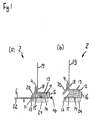
- FIG. 1 (a) shows a not yet attached plaster strip 2 in cross section, in which the receiving area is closed.
- drawn plaster strip 2 has a first leg 4, which leads from bottom to top and a second leg 6, which leads essentially from right to left on.
- a substantially rectangular receiving region 10 for a sealing tape 12 with delayed expansion adjoins to the right, projecting to the right.
- a Arm istsgewebeabites 19 is attached thereto with a welded connection.
- it is a welded joint, which has been created by ultrasonic welding by means of a separately supplied welding string 18.
- the left side of the first leg 4 and of this obliquely to the left bottom extending rounded transition between the first leg 4 and the second leg 6 are provided with a channel profiling 20.
- the second leg 6 includes a protective tab 22, on top of which is a not shown, double-sided adhesive strip, so you can easily stick a protective film for window or door openings there.
- the receiving area / enclosure area 10 comprises a top leg 13 integrally connected to the first leg 4 and projecting to the right, and a bottom area having a bottom wall 14 with an appendage to the left end of the bottom wall 14 and obliquely rightward protruding projection 15 and having a right outer wall whose upper end is bent inwardly and forms a latching with the right end of the upper side leg 13.
- a diagonally down to the left sealing lip 17 is arranged.
- the left end of the lower wall 14, the right end of the second leg 6 and the lower end of the transition between the first leg 4 and the second leg 6 is formed as a flexible, detachable connection portion 21.
- an adhesive tape 24 is attached, by means of which the plastering strip 2 can be glued to a window frame.
- FIG. 1 (b) shows the plaster strip 2 with open receiving area 10 in cross section.
- the sealing tape 12 has expanded in the transverse direction.
- the lower wall 14 has been made in one piece with the rest of the plastering strip 2, in particular with the second leg 6, with the first leg 4, with the upper side leg 13 and with the transition between the first leg 4 and the second leg 6, in one State, in the bottom wall 14 by about 90 ° or more counterclockwise compared to the in FIG. 1 drawn situation has been pivoted.
- the sealing tape 12 could be introduced longitudinally compressed and then the lower wall 14 closed and locked with the top of its right outer wall 16 opposite the right end of the upper side leg 13, whereby the sealing tape 12 is held together in the transverse direction and an expansion is prevented.
- the sealing lip 17 may consist of two soft, flexible material with respect to the rest of the plastering strip 2 and have been produced by coextrusion.
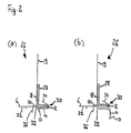
- FIG. 2 (a) shows a not yet attached plaster strip 26 in cross section, in which the receiving area 30 is closed.
- the second plaster bar 26 are over-tuning elements with the same reference numerals as in FIG. 1 designated.
- the first leg 28 projects significantly further upwards, and the reinforcing fabric 19 is fastened by means of a welding string 18 to the left side of the first leg 28.
- no adhesive tape 24 is attached.
- the receiving area 30 surrounds the sealing band 12. Its lower wall 14 is latched with its slightly upwardly projecting left end against a latching projection 32 which attaches to the underside of the transitional area between the first leg 28 and the second leg 6.
- the lower wall 14 can be flexibly pivoted about its flexibly formed transition to the right outer wall of the receiving area 30.
- a barb-like projection 34 On top of the receiving area 30 is a barb-like projection 34. Furthermore, a cover lip 36 is provided at the right end of the second leg 6, which projects downwards. This can be compared to the remaining plaster strip 26 softer, flexible material and have been prepared by coextrusion.
- FIG. 2 (b) shows the plaster strip 2 with open receiving area 10 in cross section.
- the lower wall 14 of the receiving area 30 has been released from its latching projection 32 by unlocking its left end and has been pivoted downwards.
- the lower wall 14 can be plugged either with the plaster molding in the transition between a thermal insulation attached to a building and a built-in or yet to be incorporated building component, such as a window or door frame, with. Alternatively, it can be torn off at its flexible transition area to the right outer wall.
- the sealing tape 12 is inserted upset within the receiving area 10, 30.
- a material overhang of the sealing strip at the end of the profile need not, but can still be performed so that the joint area is sealed with the utmost security.
- supernatant is a supernatant of the sealing tape at the profile ends of 3 mm mentioned. It should also be noted that a supernatant of the sealing strip in a plastering strip or a rod with 2 meters in length of, for example, both sides 2 cm manufacturing technology would be possible, this design is not buildable, since the sealing band projection is positioned incorrectly and would not ensure continuous compression. Even when cutting this profile, this design would be ineffective.
- FIG. 3 shows the plaster strip 2 in its installed state in the transition between a thermal insulation 38 and a window frame 44 in horizontal section and a detail detail view.
- a small part of a building wall 46 and a part of a window frame 44 which is inserted into a corresponding opening of the building wall 46.
- a thermal insulation 38 which is attached to the building wall 46.
- the plaster strip 2 thus lies against the underside of its adhesive tape 24 on the outer surface of the window frame 44, its right outer wall 16 abuts the gap end, its upper side leg 13 is located on the heat insulation side gap side, which lies opposite the outer surface of the window frame 44 , at.
- the detailed view of the gap between the thermal insulation 38 and the window frame 44 also shows that the outer plaster 42 extends to the channel profiling 20, where he finds good support due to the increased surface.
- the longitudinal compression of the sealing strip 12 into the receiving area 10 ensures that no shrinkage occurs at the upper and lower ends of the plastering strip 2 and that thus the upper and lower ends of the plastering strip 2 fill the gap in a sealing manner and the plastering strip 2 fits well therein fix.
- FIG. 4 shows a front view of a manufacturing machine 50 according to an embodiment of the invention.
- the manufacturing machine 50 is designed as a machine for the compressed introduction of a sealing strip in a plastic strip, in particular a plaster molding or sealing strip, and it has, seen from right to left, a support area 52, a processing area 54 and a removal area 56. Although the manufacturing machine 50 is always explained below with reference to a plaster strip, it is also suitable for the compressed introduction of a sealing strip in any plastic strip, in particular in a sealing strip.
- a controller 58 is arranged, which controls the sequence of the method for the compressed introduction of the sealing strip in the plaster molding.
- a linear unit 60 is disposed above the machining plate and extends in a horizontal direction from the left end of the machining area 54 to the right end thereof.
- a screed strip receptacle is provided directly below the underside of the movable carriage 64.
- a drive motor 62 is provided, which drives a movable carriage 64, which may be ball-bearing, via a toothed belt, not shown here.
- the movable carriage 64 is shown in a left initial position A and in a right end position B.
- a grout as shown in the FIGS. 1 and 2 is shown, placed on the right support portion 52, with a small distance to the previous plaster bar, which is still in the processing area 54.
- the movable carriage 64 is in Position A.
- the manufacturing machine 50 is started, by the drive motor 62 of the movable carriage 64 is moved over the entire length of the cleaning strip located in the processing area 54, and thereby the sealing tape 12, as shown in the Figures 5 and 6 will be explained in more detail, compressed rolled into the receiving area 10 of the plaster molding and the receiving area of the plaster molding is then closed.
- FIG. 5 shows a schematic front view of a roller assembly 66 with a guided over sealing tape 86 and a plaster strip 67, in the receiving area 10, the sealing tape 12 is introduced by means of the roller assembly 66 compressed in the longitudinal direction, according to an embodiment of the invention.
- roller assembly 66 is always explained with reference to a plaster molding, it is just as suitable for the compressed introduction a sealing strip in any plastic strip, in particular in a sealing strip.
- the roller assembly 66 can either, as in the manufacturing machine 50 in FIG. 4 realized to be arranged on a movable carriage, which is moved relative to the fixedly positioned plaster strip 67 in order to introduce the sealing strip 86 so compressed in the receiving area of the plaster strip 67.
- the roller assembly 66 may be arranged stationary, and the plaster strip 67 is moved at a certain speed relative to the roller assembly 66, so that the sealing tape 86 is introduced upset in the receiving area of the plaster strip 67.
- both the roller assembly 66 and the plaster bar 67 are moved against each other.
- the roller assembly 66 has a sealing tape feed roller 68 on which is wound a sealing tape 86 having cover tape 84 thereon and covering the adhesive underside of the sealing tape 86.
- the masking tape 84 is conveyed from the sealing tape feed roller 68 via a masking belt guide pulley 72 to a pair of rollers comprising a first masking belt guide roller 74 which may be formed as a toothed metal wheel and a second masking belt guide roller 76 which may be formed as a solid rubber roller. led away so that the cover strip 84 is removed during the unrolling of the sealing strip 86 of the sealing tape feed roller 68.
- the sealing tape 86 passes to the sealing belt upset roller 78, which has a slightly larger diameter than the following receiving area-Avemhaltrolle 80 and the subsequent receiving area-closing roller 82. From this sealing belt pinch roller 78, the sealing tape 86 is inserted into the in FIG. 5 unrecognizable receiving area 10, which is stopped by the receiving area Aufrolltrolle 80 introduced.
- the receiving area closing roller 82 arranged to the left thereof closes the receiving area of the plastering strip 67 again.
- Plaster strip 2 shown is the plaster strip 2 positioned with downwardly projecting first leg 4 relative to the roller assembly 66, wherein the reinforcing fabric 19 is already attached to the plastic profile.
- the receiving area roll-up 80 pivots the lower wall portion 14 and the right outer wall 16 of the receiving area 10 about the flexible detachable connector 21 such that the sealing belt pinch roller 78 compresses the sealing tape 86 on the upper side leg 13 in the longitudinal direction the bottom wall 14 applies.
- the receiving area closing roller 82 then pivots the lower wall 14 and the right outer wall 16 of the receiving area 10 of the plastering strip 2 such that the right outer wall 16 locks with the upper side leg 13 and closes the receiving area 10 with the sealing strip 12 now inserted therein.
- FIG. 5 The in FIG. 5
- the arrow at the bottom right indicates the plaster strip feed direction 88.
- the scraper bar 67 would be moved to introduce the sealing tape 86 through the seal belt swaging roller 78.
- the roller assembly 66 further has a cleaning strip feed roller 70, which is provided in particular for the embodiment with stationary roller assembly 66 and moving plaster strip 67.
- sealing band-upset roller 78 Below the sealing band-upset roller 78, a distance to the plaster strip 67 can be seen.
- the sealing band-upset roll 78 can also press the sealing tape 12 directly onto the plastering strip 67, so that this intermediate space is eliminated.
- the longitudinal compression of the sealing strip 12 into the receiving area 10 of the plastering strip 67 is achieved according to the roller assembly 66 by a relative to the other rollers 80 and 82 increased peripheral speed. It is advantageous to effect a peripheral speed increased by 1 to 5% and accordingly a compression of 1 to 5%.
- At least the rollers 78, 80 and 82 are connected by a common V-belt, and the circumference of the sealing belt compression roller 78 is increased by 1 to 5%, preferably by about 3%, from the circumference of the rollers 80 and 82 , As a result, a compressed introduction of the sealing strip 12 into the receiving area 10 of the plastering strip 67 is effected in a simple manner.
- FIG. 6 shows a schematic sectional view of a roller assembly 92 according to another embodiment of the invention.
- the sealing tape feed roller, the receiving area-Avemhaltrolle and the receiving area-closing roller are not shown.
- the detachment and removal of the cover strip 80 via a smaller cover band deflection roller 98 and a pair of rollers also smaller cover strip Weg slaughterrollen 100 and 102. These are arranged approximately at the level of the underside of the sealing strip compression roller 94.
- the second cover strip Wegcommendedrolle 102 is arranged too deep, this would have to be slightly shifted upwards so that it does not collide with the plastic strip 104.
- sealing tape guide roller 96 is arranged.
- the sealing tape 86 presses the sealing tape 86 directly onto the plastic strip 104 without providing a gap.
- FIG. 6 are indicated by two arrows directed to the left, the relative velocity v rel and the compression speed v ups .
- the compression speed which results from the peripheral speed of the sealing strip compression roller 94, is slightly greater than the relative speed between roller assembly 92 and plastic strip 104, so that as in FIG. 6 can also be seen on the basis of the representation of the material of the sealing strip 86, the sealing strip 86 is compressed in the longitudinal direction in the receiving area 10 of the sealing tape 104 and possibly glued.
- further special wheels may be provided in the roller assemblies 66 and 92 between the sealing tape feed roller 68 and the sealing belt pinch roller 78/94, over which the sealing tape 86 extends.
- the drive motor can be designed as a speed-controlled motor, in particular as an electric motor. This allows the sealing tape feed speed regardless of the relative movement between the sealing tape guide unit and the plaster molding set.
- the roller assembly 92 and the seal tape feed roll are integrated into a handy upsetting tool, and the reference numeral 104 does not represent a plaster molding, but rather the bottom of a gap or joint into which the sealing tape 86 is directly inserted in a swaged condition for the sealing tape 86 a plastic strip with a receiving area or the like is provided.
- sealing tape feed roller and the sealing belt compression roller 94, further special wheels may be provided over which the sealing tape 86 extends.
- the upsetting device In the use of the upsetting device, this is set at one end of the gap, and the sealing tape 86 is applied to the bottom of the gap. Then, the upsetting apparatus is moved along the nip, the sealing belt pinch roller 94 ensuring a sealing belt feed speed that is greater than the speed of longitudinal movement of the upsetting apparatus. This can be ensured by a correspondingly higher peripheral speed of the sealing strip compression roller 94.
- the compression device may have a wheel, which runs alongside the gap and thus detects the feed rate of the compression device in the longitudinal direction. This wheel may be directly or indirectly connected to the sealing band compression roller 94, which has a peripheral speed increased relative to this wheel by the desired compression to be achieved.
- the sealing tape 86 is cut off and the end of the sealing strip 86 is possibly still manually introduced into the gap end.
- the compression with which the sealing tape 86 is inserted into the gap can be adjusted as desired.
- a drive motor can be provided.
- the sealing tape is introduced into the gap in a simple manner and with exactly the desired compression.
- the proper compressed insertion of the sealing tape is thus guaranteed and can be proved later, for example by re-measuring the cover / cover paper.
- FIG. 7 shows a sealing tape 114 in its inserted state in the gap between a building outer shell 110 and a window frame 112 in horizontal section.
- FIG. 7 a bivalve masonry with a building inner shell 106, with a building outer shell 110 and with an air and insulating layer 108 disposed therebetween is shown.
- a window frame 112 is attached to the building inner shell 106 with a suitable insulating material.
- Between the building outer shell 110 and the front of the window frame 112 is an elongated gap, which in FIG. 7 is formed in the building outer shell 110.
- a sealing tape 114 is inserted compressed in the longitudinal direction.
- the gap may also be formed deeper and extend, for example, up to the air and insulation layer 108 or up to the building inner shell 106, in which case the thickness of the sealing tape 114 is suitable to choose.
- FIG. 8 (a) shows a not yet attached plastic strip 116 in cross section.
- the plastic strip 116 comprises a receiving area 118 which, like the enclosure area 10 of the plastering strip 2, has a lower wall 122, a projection 124 which projects at the right end of the lower wall 122 and projects obliquely upwards to the left, a left outer wall 126 located at the lower level Wall 122 connects and whose upper end is bent inwards and forms a latching with the left end of Abdecklasche 134, and parallel to the lower wall 122 extending upper Abdecklasche 134, whose right end is bent down and at the right end of the lower wall 122nd forms a flexible, releasable connection region 136 with the lower wall 122.
- an adhesive tape 128 is attached, by means of which the plastic strip 116 can be glued to a window frame or the like.
- a diagonally downwardly disposed sealing lip 124 is arranged.
- the longitudinal compression of the sealing strip 120 into the receiving area 118 ensures that no shrinkage occurs at the upper and lower ends of the plastic strip 116.
- FIG. 8 (b) shows the plastic strip 116 with detached protective tab 132 and Abdecklasche 134th
- the protective tab 132 and the cover tab 134 are separated from the rest of the plastic strip 116 and pulled away to the right. This is done in practice by kinking or separating the protective tab 132, whereby the flexible detachable connection portion 136 is separated, and by subsequently pulling the protective tab 132 with the cover flap 134 hanging thereon to the right. Accordingly, the sealing tape 120 is now free for expansion.
- the sealing tape 120 has expanded transversely.
- an advantageous and secure seal a transition between two building components can be achieved.
- Figure 8 (c) shows the plastic strip 116 in its in the gap between the plaster 124, 146 and a window frame 140 introduced state.
- a small part of a building wall 138 and a part of a window frame 140 which is inserted into a corresponding opening of the building wall 138.
- a base plaster layer 144 and a cover plaster layer 146 arranged thereon can be seen.
- a gap or transition in which the plastic strip 116 is inserted with its receiving area 118 is a gap or transition in which the plastic strip 116 is inserted with its receiving area 118.
- a masking paper has previously been released from the adhesive tape 128, and the plastic strip 116 has been glued to the window frame side side surface of the gap with the adhesive tape 128.
- the protective tab 132 is bent and pulled out together with the Abdecklasche 134 from the gap.
- the sealing tape 120 now expands in the transverse direction as shown in FIG. 8 (b) is shown, and presses close to the plaster side surface of the gap.
- the plastic strip 116 is a sufficiently good seal of the gap, also there is still a certain additional attachment effect.
- FIG. 9 shows the plastic strip 116 in its in the gap between a clinker brick 154 and a metal angle 150 introduced state.
- a mineral wool insulating layer 148 In front of the building wall 138, which may be made of concrete, there is a mineral wool insulating layer 148, to which in turn by means of a mortar 152 a clinker brick lining 154 is attached. Between the building wall 138 and the mineral wool insulation layer 148, a metal angle rail or a metal bracket 150 is attached, which is located to the left of the mineral wool insulation layer 148, the mortar 152 and the brick facing 154 extends to a level of the outer surface of the brick facing 154. Approximately at the level of the outer surface of the mineral wool insulating layer 148, the metal angle 150 kinks to the left. In the gap between the clinker brick 154 and the front portion of the metal angle 150, there is a gap between clinker brick 154 and the front portion of the metal angle 150.
- the plastic strip 116 has been inserted and adhered to the underside of the adhesive tape 158 on the metal angle-side side surface of the gap.
- the protective tab 132 has been released, for example, by bending off the lower wall 122 of the plastic strip 116 and has been pulled outwards out of the gap together with the cover tab 134.
- the sealing tape 120 has expanded in the transverse direction and pressed against the clinker side side surface of the gap. This gap is thus well sealed and there is also an additional attachment effect.
- FIGS. 8 and 9 is ensured by the longitudinal compression insertion of the sealing strip 120 into the receiving area 116 and the particular flush insertion of the plastic strip 116 in the gap at the top and bottom of the column end that no shrinkage occurs at the top and bottom of the column end and thus that the upper and lower ends the plastic strip 116 filling the gap sealing and the plastic strip 116 can fix it well.
Landscapes
- Engineering & Computer Science (AREA)
- Architecture (AREA)
- Civil Engineering (AREA)
- Structural Engineering (AREA)
- Mechanical Engineering (AREA)
- Specific Sealing Or Ventilating Devices For Doors And Windows (AREA)
- Building Environments (AREA)
Priority Applications (2)
| Application Number | Priority Date | Filing Date | Title |
|---|---|---|---|
| PL09167277T PL2151532T3 (pl) | 2008-08-06 | 2009-08-05 | Listwa z tworzywa sztucznego |
| EP16184650.6A EP3130722B1 (fr) | 2008-08-06 | 2009-08-05 | Baguette en matiere plastique |
Applications Claiming Priority (1)
| Application Number | Priority Date | Filing Date | Title |
|---|---|---|---|
| DE102008036656A DE102008036656A1 (de) | 2008-08-06 | 2008-08-06 | Kunststoff-Leiste |
Related Child Applications (2)
| Application Number | Title | Priority Date | Filing Date |
|---|---|---|---|
| EP16184650.6A Division EP3130722B1 (fr) | 2008-08-06 | 2009-08-05 | Baguette en matiere plastique |
| EP16184650.6A Division-Into EP3130722B1 (fr) | 2008-08-06 | 2009-08-05 | Baguette en matiere plastique |
Publications (3)
| Publication Number | Publication Date |
|---|---|
| EP2151532A2 true EP2151532A2 (fr) | 2010-02-10 |
| EP2151532A3 EP2151532A3 (fr) | 2012-07-18 |
| EP2151532B1 EP2151532B1 (fr) | 2016-12-28 |
Family
ID=41137110
Family Applications (2)
| Application Number | Title | Priority Date | Filing Date |
|---|---|---|---|
| EP09167277.4A Active EP2151532B1 (fr) | 2008-08-06 | 2009-08-05 | Profilé en matière plastique |
| EP16184650.6A Active EP3130722B1 (fr) | 2008-08-06 | 2009-08-05 | Baguette en matiere plastique |
Family Applications After (1)
| Application Number | Title | Priority Date | Filing Date |
|---|---|---|---|
| EP16184650.6A Active EP3130722B1 (fr) | 2008-08-06 | 2009-08-05 | Baguette en matiere plastique |
Country Status (3)
| Country | Link |
|---|---|
| EP (2) | EP2151532B1 (fr) |
| DE (1) | DE102008036656A1 (fr) |
| PL (1) | PL2151532T3 (fr) |
Cited By (2)
| Publication number | Priority date | Publication date | Assignee | Title |
|---|---|---|---|---|
| EP2363562A3 (fr) * | 2010-03-05 | 2016-07-13 | Patech GmbH | Baguette de profilé étanche |
| EP3569790A1 (fr) * | 2018-05-18 | 2019-11-20 | Braun, August | Bande de crépissage ainsi que transition de bâtiment pourvu de bande de crépissage |
Families Citing this family (7)
| Publication number | Priority date | Publication date | Assignee | Title |
|---|---|---|---|---|
| DE102009038934A1 (de) | 2009-08-26 | 2011-03-03 | August Braun | Anputzleiste sowie Anordnung von zwei Anputzleisten |
| DE202012007697U1 (de) | 2012-08-10 | 2012-09-11 | August Braun | Anputzleiste, Abschlussschiene und Putz-Eckleiste |
| DE102018105610A1 (de) * | 2018-03-12 | 2019-09-12 | August Braun | Anputzleiste zur Anordnung an einem Gebäude-Übergang sowie Gebäude-Übergang damit |
| DE102019127008A1 (de) * | 2019-10-08 | 2021-04-08 | Protektorwerk Florenz Maisch Gmbh & Co. Kg | Anputzdichtleiste |
| AT523847B1 (de) * | 2021-02-01 | 2021-12-15 | K Uni Kunststoffproduktions Und Handels Gmbh | Anschlussprofil für an putz angrenzende bauteile |
| AT524937B1 (de) | 2022-02-21 | 2022-11-15 | K Uni Kunststoffproduktions Und Handels Gmbh | Anschlussprofil für an putz angrenzende bauteile |
| AT18031U1 (de) * | 2022-06-15 | 2023-11-15 | Mick Mag Christian | Anputzdichtleiste |
Family Cites Families (3)
| Publication number | Priority date | Publication date | Assignee | Title |
|---|---|---|---|---|
| DE3405512A1 (de) * | 1984-02-16 | 1985-08-29 | Paul Anton GmbH, 6603 Sulzbach | Verfahren und vorrichtung zum formschluessigen eindruecken von dichtungsprofilen in rahmenprofile |
| AT5077U1 (de) * | 2000-09-05 | 2002-03-25 | Technoplast Kunststofftechnik | Verfahren und vorrichtung zur herstellung von kunststoffprofilen |
| DE102005057778A1 (de) * | 2005-12-02 | 2007-06-06 | August Braun | Putzabschlussleiste für eine Putzschicht auf einer Wärmedämmung |
-
2008
- 2008-08-06 DE DE102008036656A patent/DE102008036656A1/de not_active Withdrawn
-
2009
- 2009-08-05 EP EP09167277.4A patent/EP2151532B1/fr active Active
- 2009-08-05 PL PL09167277T patent/PL2151532T3/pl unknown
- 2009-08-05 EP EP16184650.6A patent/EP3130722B1/fr active Active
Cited By (4)
| Publication number | Priority date | Publication date | Assignee | Title |
|---|---|---|---|---|
| EP2363562A3 (fr) * | 2010-03-05 | 2016-07-13 | Patech GmbH | Baguette de profilé étanche |
| EP3569790A1 (fr) * | 2018-05-18 | 2019-11-20 | Braun, August | Bande de crépissage ainsi que transition de bâtiment pourvu de bande de crépissage |
| EP3569791A1 (fr) * | 2018-05-18 | 2019-11-20 | Braun, August | Baguette de limitation de crépi, utilisation d'une bande adhésive en mousse double face dans une baguette de limitation de crépi destinée à être placée sur une transition de bâtiment ainsi que transition de bâtiment doté d'une telle baguette de limitation de crépi |
| EP3808919A3 (fr) * | 2018-05-18 | 2021-05-05 | Braun, August | Baguette de limitation de crépi, utilisation d'une bande adhésive en mousse double face dans une baguette de limitation de crépi destinée à être placée sur une transition de bâtiment ainsi que transition de bâtiment doté d'une telle baguette de limitation de crépi |
Also Published As
| Publication number | Publication date |
|---|---|
| EP3130722A1 (fr) | 2017-02-15 |
| EP2151532A3 (fr) | 2012-07-18 |
| PL2151532T3 (pl) | 2017-07-31 |
| EP2151532B1 (fr) | 2016-12-28 |
| EP3130722B1 (fr) | 2020-10-21 |
| DE102008036656A1 (de) | 2010-02-25 |
Similar Documents
| Publication | Publication Date | Title |
|---|---|---|
| EP2151532B1 (fr) | Profilé en matière plastique | |
| EP2222930B1 (fr) | Procédé de fixation d'un panneau ou d'une vitre de verre dans un élément de cadre et élément de joint destiné à être employé dans un tel procédé | |
| EP2404008B1 (fr) | Dispositif d'étanchéité sur un joint dans une construction | |
| EP2990575B1 (fr) | Bande étanche pour l'étanchéification d'un joint | |
| EP1808565B1 (fr) | Agencement d'étanchéité et profilé pour un agencement d'étanchéité | |
| EP3256666B1 (fr) | Bande d'étanchéité de jointure universelle pour différentes dimensions de profilé et dispositif d'étanchéité pourvu d'une telle bande d'étanchéité de jointure | |
| EP4036346B1 (fr) | Profilé de raccordement pour composants adjacents au crépi | |
| DE3486392T2 (de) | Klebemontage von Scheiben in eine Öffung, insbesondere von Windschutzscheiben für Kraftfahrzeuge, zur erleichterten Demontage. | |
| EP2281971B1 (fr) | Baguette de bord pour une couche d'enduit sur un élément d'isolation thermique | |
| DE20008712U1 (de) | Profilleiste zum Abdichten einer Bewegungsfuge zwischen einem Bauteil und einer Putzschicht | |
| AT503272A2 (de) | Vorrichtung zum aufbringen diverser baustoffmaterialien auf einer wand | |
| EP0278364A2 (fr) | Dispositif pour le recouvrement d'ouvertures de portes et de fenêtres dans les bâtiments | |
| EP2093339A2 (fr) | Dispositif de fixation d'un joint sur une plaque de coffrage | |
| DE102013110110A1 (de) | Anputzleiste, Abschlussschiene und Putz-Eckleiste und Verfahren zum Herstellen derselben | |
| EP2186957B1 (fr) | Garniture de joint et son procédé de fabrication | |
| EP4446551B1 (fr) | Profilé de raccordement pour composants adjacents sur un enduit | |
| DE4236489C2 (de) | Verfahren zum Einbau von Dichtwandfolien in eine Dichtungsschlitzwand und Einrichtung zur Durchführung des Verfahrens | |
| EP1777359A2 (fr) | Bande pour crépi et bande pour crépi enroulée | |
| AT503760B1 (de) | Einputzleiste sowie verfahren zur herstellung einer einputzleiste | |
| EP3608485B1 (fr) | Profilé d'absorption de mouvement | |
| EP3502397B1 (fr) | Élément d'étanchéification des ouvrages, dispositif d'étanchéification des ouvrages, raccordement de fenêtre pourvu de dispositif d'étanchéification des ouvrages et procédé d'étanchéification | |
| DE29511769U1 (de) | Fugenabdeckung | |
| DE10311506A1 (de) | Luftdichter Wandabschluß zwischen Wand und Decke oder zwischen Wand und Wand eines Gebäudes | |
| EP1403440A1 (fr) | Raccordement hermetique entre mur et plafond ou mur et mur, par exemple dans un grenier | |
| EP3266972A1 (fr) | Barre de liaison destinée à assembler un appui de fenêtre et une construction |
Legal Events
| Date | Code | Title | Description |
|---|---|---|---|
| PUAI | Public reference made under article 153(3) epc to a published international application that has entered the european phase |
Free format text: ORIGINAL CODE: 0009012 |
|
| AK | Designated contracting states |
Kind code of ref document: A2 Designated state(s): AT BE BG CH CY CZ DE DK EE ES FI FR GB GR HR HU IE IS IT LI LT LU LV MC MK MT NL NO PL PT RO SE SI SK SM TR |
|
| RIC1 | Information provided on ipc code assigned before grant |
Ipc: E04F 13/06 20060101ALI20120130BHEP Ipc: E06B 1/68 20060101ALI20120130BHEP Ipc: E04G 21/30 20060101ALI20120130BHEP Ipc: E04F 13/04 20060101AFI20120130BHEP |
|
| PUAL | Search report despatched |
Free format text: ORIGINAL CODE: 0009013 |
|
| AK | Designated contracting states |
Kind code of ref document: A3 Designated state(s): AT BE BG CH CY CZ DE DK EE ES FI FR GB GR HR HU IE IS IT LI LT LU LV MC MK MT NL NO PL PT RO SE SI SK SM TR |
|
| RIC1 | Information provided on ipc code assigned before grant |
Ipc: E04F 13/04 20060101AFI20120611BHEP Ipc: E06B 1/68 20060101ALI20120611BHEP Ipc: E04F 13/06 20060101ALI20120611BHEP Ipc: E04G 21/30 20060101ALI20120611BHEP |
|
| 17P | Request for examination filed |
Effective date: 20130117 |
|
| 17Q | First examination report despatched |
Effective date: 20160224 |
|
| GRAP | Despatch of communication of intention to grant a patent |
Free format text: ORIGINAL CODE: EPIDOSNIGR1 |
|
| RAP1 | Party data changed (applicant data changed or rights of an application transferred) |
Owner name: BRAUN, AUGUST |
|
| RIN1 | Information on inventor provided before grant (corrected) |
Inventor name: BRAUN, AUGUST |
|
| INTG | Intention to grant announced |
Effective date: 20160811 |
|
| GRAS | Grant fee paid |
Free format text: ORIGINAL CODE: EPIDOSNIGR3 |
|
| GRAA | (expected) grant |
Free format text: ORIGINAL CODE: 0009210 |
|
| AK | Designated contracting states |
Kind code of ref document: B1 Designated state(s): AT BE BG CH CY CZ DE DK EE ES FI FR GB GR HR HU IE IS IT LI LT LU LV MC MK MT NL NO PL PT RO SE SI SK SM TR |
|
| REG | Reference to a national code |
Ref country code: GB Ref legal event code: FG4D Free format text: NOT ENGLISH |
|
| REG | Reference to a national code |
Ref country code: CH Ref legal event code: EP |
|
| REG | Reference to a national code |
Ref country code: AT Ref legal event code: REF Ref document number: 857434 Country of ref document: AT Kind code of ref document: T Effective date: 20170115 |
|
| REG | Reference to a national code |
Ref country code: IE Ref legal event code: FG4D Free format text: LANGUAGE OF EP DOCUMENT: GERMAN |
|
| REG | Reference to a national code |
Ref country code: DE Ref legal event code: R096 Ref document number: 502009013514 Country of ref document: DE |
|
| PG25 | Lapsed in a contracting state [announced via postgrant information from national office to epo] |
Ref country code: LV Free format text: LAPSE BECAUSE OF FAILURE TO SUBMIT A TRANSLATION OF THE DESCRIPTION OR TO PAY THE FEE WITHIN THE PRESCRIBED TIME-LIMIT Effective date: 20161228 |
|
| REG | Reference to a national code |
Ref country code: CH Ref legal event code: NV Representative=s name: THOMANNFISCHER, CH |
|
| REG | Reference to a national code |
Ref country code: LT Ref legal event code: MG4D |
|
| PG25 | Lapsed in a contracting state [announced via postgrant information from national office to epo] |
Ref country code: SE Free format text: LAPSE BECAUSE OF FAILURE TO SUBMIT A TRANSLATION OF THE DESCRIPTION OR TO PAY THE FEE WITHIN THE PRESCRIBED TIME-LIMIT Effective date: 20161228 Ref country code: GR Free format text: LAPSE BECAUSE OF FAILURE TO SUBMIT A TRANSLATION OF THE DESCRIPTION OR TO PAY THE FEE WITHIN THE PRESCRIBED TIME-LIMIT Effective date: 20170329 Ref country code: NO Free format text: LAPSE BECAUSE OF FAILURE TO SUBMIT A TRANSLATION OF THE DESCRIPTION OR TO PAY THE FEE WITHIN THE PRESCRIBED TIME-LIMIT Effective date: 20170328 Ref country code: LT Free format text: LAPSE BECAUSE OF FAILURE TO SUBMIT A TRANSLATION OF THE DESCRIPTION OR TO PAY THE FEE WITHIN THE PRESCRIBED TIME-LIMIT Effective date: 20161228 |
|
| REG | Reference to a national code |
Ref country code: NL Ref legal event code: MP Effective date: 20161228 |
|
| PG25 | Lapsed in a contracting state [announced via postgrant information from national office to epo] |
Ref country code: FI Free format text: LAPSE BECAUSE OF FAILURE TO SUBMIT A TRANSLATION OF THE DESCRIPTION OR TO PAY THE FEE WITHIN THE PRESCRIBED TIME-LIMIT Effective date: 20161228 Ref country code: HR Free format text: LAPSE BECAUSE OF FAILURE TO SUBMIT A TRANSLATION OF THE DESCRIPTION OR TO PAY THE FEE WITHIN THE PRESCRIBED TIME-LIMIT Effective date: 20161228 |
|
| PG25 | Lapsed in a contracting state [announced via postgrant information from national office to epo] |
Ref country code: NL Free format text: LAPSE BECAUSE OF FAILURE TO SUBMIT A TRANSLATION OF THE DESCRIPTION OR TO PAY THE FEE WITHIN THE PRESCRIBED TIME-LIMIT Effective date: 20161228 |
|
| REG | Reference to a national code |
Ref country code: DE Ref legal event code: R082 Ref document number: 502009013514 Country of ref document: DE Representative=s name: SCHMITT-NILSON SCHRAUD WAIBEL WOHLFROM PATENTA, DE |
|
| PG25 | Lapsed in a contracting state [announced via postgrant information from national office to epo] |
Ref country code: SK Free format text: LAPSE BECAUSE OF FAILURE TO SUBMIT A TRANSLATION OF THE DESCRIPTION OR TO PAY THE FEE WITHIN THE PRESCRIBED TIME-LIMIT Effective date: 20161228 Ref country code: EE Free format text: LAPSE BECAUSE OF FAILURE TO SUBMIT A TRANSLATION OF THE DESCRIPTION OR TO PAY THE FEE WITHIN THE PRESCRIBED TIME-LIMIT Effective date: 20161228 Ref country code: IS Free format text: LAPSE BECAUSE OF FAILURE TO SUBMIT A TRANSLATION OF THE DESCRIPTION OR TO PAY THE FEE WITHIN THE PRESCRIBED TIME-LIMIT Effective date: 20170428 Ref country code: RO Free format text: LAPSE BECAUSE OF FAILURE TO SUBMIT A TRANSLATION OF THE DESCRIPTION OR TO PAY THE FEE WITHIN THE PRESCRIBED TIME-LIMIT Effective date: 20161228 |
|
| REG | Reference to a national code |
Ref country code: FR Ref legal event code: PLFP Year of fee payment: 9 |
|
| PG25 | Lapsed in a contracting state [announced via postgrant information from national office to epo] |
Ref country code: PT Free format text: LAPSE BECAUSE OF FAILURE TO SUBMIT A TRANSLATION OF THE DESCRIPTION OR TO PAY THE FEE WITHIN THE PRESCRIBED TIME-LIMIT Effective date: 20170428 Ref country code: SM Free format text: LAPSE BECAUSE OF FAILURE TO SUBMIT A TRANSLATION OF THE DESCRIPTION OR TO PAY THE FEE WITHIN THE PRESCRIBED TIME-LIMIT Effective date: 20161228 Ref country code: BG Free format text: LAPSE BECAUSE OF FAILURE TO SUBMIT A TRANSLATION OF THE DESCRIPTION OR TO PAY THE FEE WITHIN THE PRESCRIBED TIME-LIMIT Effective date: 20170328 Ref country code: ES Free format text: LAPSE BECAUSE OF FAILURE TO SUBMIT A TRANSLATION OF THE DESCRIPTION OR TO PAY THE FEE WITHIN THE PRESCRIBED TIME-LIMIT Effective date: 20161228 |
|
| REG | Reference to a national code |
Ref country code: DE Ref legal event code: R097 Ref document number: 502009013514 Country of ref document: DE |
|
| PLBE | No opposition filed within time limit |
Free format text: ORIGINAL CODE: 0009261 |
|
| STAA | Information on the status of an ep patent application or granted ep patent |
Free format text: STATUS: NO OPPOSITION FILED WITHIN TIME LIMIT |
|
| PG25 | Lapsed in a contracting state [announced via postgrant information from national office to epo] |
Ref country code: DK Free format text: LAPSE BECAUSE OF FAILURE TO SUBMIT A TRANSLATION OF THE DESCRIPTION OR TO PAY THE FEE WITHIN THE PRESCRIBED TIME-LIMIT Effective date: 20161228 |
|
| 26N | No opposition filed |
Effective date: 20170929 |
|
| PG25 | Lapsed in a contracting state [announced via postgrant information from national office to epo] |
Ref country code: SI Free format text: LAPSE BECAUSE OF FAILURE TO SUBMIT A TRANSLATION OF THE DESCRIPTION OR TO PAY THE FEE WITHIN THE PRESCRIBED TIME-LIMIT Effective date: 20161228 |
|
| PG25 | Lapsed in a contracting state [announced via postgrant information from national office to epo] |
Ref country code: MC Free format text: LAPSE BECAUSE OF FAILURE TO SUBMIT A TRANSLATION OF THE DESCRIPTION OR TO PAY THE FEE WITHIN THE PRESCRIBED TIME-LIMIT Effective date: 20161228 |
|
| GBPC | Gb: european patent ceased through non-payment of renewal fee |
Effective date: 20170805 |
|
| REG | Reference to a national code |
Ref country code: BE Ref legal event code: MM Effective date: 20170831 |
|
| REG | Reference to a national code |
Ref country code: IE Ref legal event code: MM4A |
|
| PG25 | Lapsed in a contracting state [announced via postgrant information from national office to epo] |
Ref country code: LU Free format text: LAPSE BECAUSE OF NON-PAYMENT OF DUE FEES Effective date: 20170805 |
|
| PG25 | Lapsed in a contracting state [announced via postgrant information from national office to epo] |
Ref country code: GB Free format text: LAPSE BECAUSE OF NON-PAYMENT OF DUE FEES Effective date: 20170805 Ref country code: IE Free format text: LAPSE BECAUSE OF NON-PAYMENT OF DUE FEES Effective date: 20170805 |
|
| REG | Reference to a national code |
Ref country code: FR Ref legal event code: PLFP Year of fee payment: 10 |
|
| PG25 | Lapsed in a contracting state [announced via postgrant information from national office to epo] |
Ref country code: BE Free format text: LAPSE BECAUSE OF NON-PAYMENT OF DUE FEES Effective date: 20170831 |
|
| PG25 | Lapsed in a contracting state [announced via postgrant information from national office to epo] |
Ref country code: MT Free format text: LAPSE BECAUSE OF FAILURE TO SUBMIT A TRANSLATION OF THE DESCRIPTION OR TO PAY THE FEE WITHIN THE PRESCRIBED TIME-LIMIT Effective date: 20161228 |
|
| PG25 | Lapsed in a contracting state [announced via postgrant information from national office to epo] |
Ref country code: HU Free format text: LAPSE BECAUSE OF FAILURE TO SUBMIT A TRANSLATION OF THE DESCRIPTION OR TO PAY THE FEE WITHIN THE PRESCRIBED TIME-LIMIT; INVALID AB INITIO Effective date: 20090805 |
|
| PG25 | Lapsed in a contracting state [announced via postgrant information from national office to epo] |
Ref country code: CY Free format text: LAPSE BECAUSE OF NON-PAYMENT OF DUE FEES Effective date: 20161228 |
|
| PG25 | Lapsed in a contracting state [announced via postgrant information from national office to epo] |
Ref country code: MK Free format text: LAPSE BECAUSE OF FAILURE TO SUBMIT A TRANSLATION OF THE DESCRIPTION OR TO PAY THE FEE WITHIN THE PRESCRIBED TIME-LIMIT Effective date: 20161228 |
|
| PG25 | Lapsed in a contracting state [announced via postgrant information from national office to epo] |
Ref country code: TR Free format text: LAPSE BECAUSE OF FAILURE TO SUBMIT A TRANSLATION OF THE DESCRIPTION OR TO PAY THE FEE WITHIN THE PRESCRIBED TIME-LIMIT Effective date: 20161228 |
|
| REG | Reference to a national code |
Ref country code: FR Ref legal event code: PLFP Year of fee payment: 14 |
|
| REG | Reference to a national code |
Ref country code: DE Ref legal event code: R081 Ref document number: 502009013514 Country of ref document: DE Owner name: BRAUN, MAGDALENA, CH Free format text: FORMER OWNER: BRAUN, AUGUST, CESKE BUDEJOVICE, CZ |
|
| REG | Reference to a national code |
Ref country code: AT Ref legal event code: PC Ref document number: 857434 Country of ref document: AT Kind code of ref document: T Owner name: MAGDALENA BRAUN, CH Effective date: 20230508 |
|
| P01 | Opt-out of the competence of the unified patent court (upc) registered |
Effective date: 20230527 |
|
| PGFP | Annual fee paid to national office [announced via postgrant information from national office to epo] |
Ref country code: PL Payment date: 20250725 Year of fee payment: 17 Ref country code: IT Payment date: 20250829 Year of fee payment: 17 |
|
| PGFP | Annual fee paid to national office [announced via postgrant information from national office to epo] |
Ref country code: AT Payment date: 20250819 Year of fee payment: 17 Ref country code: FR Payment date: 20250821 Year of fee payment: 17 |
|
| PGFP | Annual fee paid to national office [announced via postgrant information from national office to epo] |
Ref country code: CH Payment date: 20250901 Year of fee payment: 17 |
|
| PGFP | Annual fee paid to national office [announced via postgrant information from national office to epo] |
Ref country code: CZ Payment date: 20250723 Year of fee payment: 17 |
|
| PGFP | Annual fee paid to national office [announced via postgrant information from national office to epo] |
Ref country code: DE Payment date: 20251030 Year of fee payment: 17 |
|
| REG | Reference to a national code |
Ref country code: CH Ref legal event code: R18 Free format text: ST27 STATUS EVENT CODE: U-0-0-R10-R18 (AS PROVIDED BY THE NATIONAL OFFICE) Effective date: 20260211 |