EP2151603A1 - Unite motrice et moto equipee de celle-ci - Google Patents
Unite motrice et moto equipee de celle-ci Download PDFInfo
- Publication number
- EP2151603A1 EP2151603A1 EP08827752A EP08827752A EP2151603A1 EP 2151603 A1 EP2151603 A1 EP 2151603A1 EP 08827752 A EP08827752 A EP 08827752A EP 08827752 A EP08827752 A EP 08827752A EP 2151603 A1 EP2151603 A1 EP 2151603A1
- Authority
- EP
- European Patent Office
- Prior art keywords
- shaft
- gear
- clutch
- rotation
- kick
- Prior art date
- Legal status (The legal status is an assumption and is not a legal conclusion. Google has not performed a legal analysis and makes no representation as to the accuracy of the status listed.)
- Withdrawn
Links
Images


Classifications
-
- F—MECHANICAL ENGINEERING; LIGHTING; HEATING; WEAPONS; BLASTING
- F16—ENGINEERING ELEMENTS AND UNITS; GENERAL MEASURES FOR PRODUCING AND MAINTAINING EFFECTIVE FUNCTIONING OF MACHINES OR INSTALLATIONS; THERMAL INSULATION IN GENERAL
- F16H—GEARING
- F16H3/00—Toothed gearings for conveying rotary motion with variable gear ratio or for reversing rotary motion
- F16H3/02—Toothed gearings for conveying rotary motion with variable gear ratio or for reversing rotary motion without gears having orbital motion
- F16H3/08—Toothed gearings for conveying rotary motion with variable gear ratio or for reversing rotary motion without gears having orbital motion exclusively or essentially with continuously meshing gears, that can be disengaged from their shafts
- F16H3/087—Toothed gearings for conveying rotary motion with variable gear ratio or for reversing rotary motion without gears having orbital motion exclusively or essentially with continuously meshing gears, that can be disengaged from their shafts characterised by the disposition of the gears
- F16H3/093—Toothed gearings for conveying rotary motion with variable gear ratio or for reversing rotary motion without gears having orbital motion exclusively or essentially with continuously meshing gears, that can be disengaged from their shafts characterised by the disposition of the gears with two or more countershafts
-
- B—PERFORMING OPERATIONS; TRANSPORTING
- B62—LAND VEHICLES FOR TRAVELLING OTHERWISE THAN ON RAILS
- B62M—RIDER PROPULSION OF WHEELED VEHICLES OR SLEDGES; POWERED PROPULSION OF SLEDGES OR SINGLE-TRACK CYCLES; TRANSMISSIONS SPECIALLY ADAPTED FOR SUCH VEHICLES
- B62M7/00—Motorcycles characterised by position of motor or engine
- B62M7/12—Motorcycles characterised by position of motor or engine with the engine beside or within the driven wheel
-
- F—MECHANICAL ENGINEERING; LIGHTING; HEATING; WEAPONS; BLASTING
- F16—ENGINEERING ELEMENTS AND UNITS; GENERAL MEASURES FOR PRODUCING AND MAINTAINING EFFECTIVE FUNCTIONING OF MACHINES OR INSTALLATIONS; THERMAL INSULATION IN GENERAL
- F16D—COUPLINGS FOR TRANSMITTING ROTATION; CLUTCHES; BRAKES
- F16D21/00—Systems comprising a plurality of actuated clutches
- F16D21/02—Systems comprising a plurality of actuated clutches for interconnecting three or more shafts or other transmission members in different ways
- F16D21/04—Systems comprising a plurality of actuated clutches for interconnecting three or more shafts or other transmission members in different ways with a shaft carrying a number of rotatable transmission members, e.g. gears, each of which can be connected to the shaft by a clutching member or members between the shaft and the hub of the transmission member
-
- F—MECHANICAL ENGINEERING; LIGHTING; HEATING; WEAPONS; BLASTING
- F16—ENGINEERING ELEMENTS AND UNITS; GENERAL MEASURES FOR PRODUCING AND MAINTAINING EFFECTIVE FUNCTIONING OF MACHINES OR INSTALLATIONS; THERMAL INSULATION IN GENERAL
- F16D—COUPLINGS FOR TRANSMITTING ROTATION; CLUTCHES; BRAKES
- F16D21/00—Systems comprising a plurality of actuated clutches
- F16D21/02—Systems comprising a plurality of actuated clutches for interconnecting three or more shafts or other transmission members in different ways
- F16D21/06—Systems comprising a plurality of actuated clutches for interconnecting three or more shafts or other transmission members in different ways at least two driving shafts or two driven shafts being concentric
-
- F—MECHANICAL ENGINEERING; LIGHTING; HEATING; WEAPONS; BLASTING
- F16—ENGINEERING ELEMENTS AND UNITS; GENERAL MEASURES FOR PRODUCING AND MAINTAINING EFFECTIVE FUNCTIONING OF MACHINES OR INSTALLATIONS; THERMAL INSULATION IN GENERAL
- F16D—COUPLINGS FOR TRANSMITTING ROTATION; CLUTCHES; BRAKES
- F16D25/00—Fluid-actuated clutches
- F16D25/06—Fluid-actuated clutches in which the fluid actuates a piston incorporated in, i.e. rotating with the clutch
- F16D25/062—Fluid-actuated clutches in which the fluid actuates a piston incorporated in, i.e. rotating with the clutch the clutch having friction surfaces
- F16D25/063—Fluid-actuated clutches in which the fluid actuates a piston incorporated in, i.e. rotating with the clutch the clutch having friction surfaces with clutch members exclusively moving axially
- F16D25/0635—Fluid-actuated clutches in which the fluid actuates a piston incorporated in, i.e. rotating with the clutch the clutch having friction surfaces with clutch members exclusively moving axially with flat friction surfaces, e.g. discs
- F16D25/0638—Fluid-actuated clutches in which the fluid actuates a piston incorporated in, i.e. rotating with the clutch the clutch having friction surfaces with clutch members exclusively moving axially with flat friction surfaces, e.g. discs with more than two discs, e.g. multiple lamellae
-
- F—MECHANICAL ENGINEERING; LIGHTING; HEATING; WEAPONS; BLASTING
- F16—ENGINEERING ELEMENTS AND UNITS; GENERAL MEASURES FOR PRODUCING AND MAINTAINING EFFECTIVE FUNCTIONING OF MACHINES OR INSTALLATIONS; THERMAL INSULATION IN GENERAL
- F16D—COUPLINGS FOR TRANSMITTING ROTATION; CLUTCHES; BRAKES
- F16D25/00—Fluid-actuated clutches
- F16D25/10—Clutch systems with a plurality of fluid-actuated clutches
-
- F—MECHANICAL ENGINEERING; LIGHTING; HEATING; WEAPONS; BLASTING
- F16—ENGINEERING ELEMENTS AND UNITS; GENERAL MEASURES FOR PRODUCING AND MAINTAINING EFFECTIVE FUNCTIONING OF MACHINES OR INSTALLATIONS; THERMAL INSULATION IN GENERAL
- F16D—COUPLINGS FOR TRANSMITTING ROTATION; CLUTCHES; BRAKES
- F16D47/00—Systems of clutches, or clutches and couplings, comprising devices of types grouped under at least two of the following sets of groups: F16D1/00 - F16D9/00, F16D11/00 - F16D23/00, F16D25/00 - F16D29/00, F16D31/00 - F16D39/00, F16D41/00 - F16D45/00
-
- F—MECHANICAL ENGINEERING; LIGHTING; HEATING; WEAPONS; BLASTING
- F16—ENGINEERING ELEMENTS AND UNITS; GENERAL MEASURES FOR PRODUCING AND MAINTAINING EFFECTIVE FUNCTIONING OF MACHINES OR INSTALLATIONS; THERMAL INSULATION IN GENERAL
- F16D—COUPLINGS FOR TRANSMITTING ROTATION; CLUTCHES; BRAKES
- F16D48/00—External control of clutches
- F16D48/02—Control by fluid pressure
- F16D48/0206—Control by fluid pressure in a system with a plurality of fluid-actuated clutches
-
- F—MECHANICAL ENGINEERING; LIGHTING; HEATING; WEAPONS; BLASTING
- F16—ENGINEERING ELEMENTS AND UNITS; GENERAL MEASURES FOR PRODUCING AND MAINTAINING EFFECTIVE FUNCTIONING OF MACHINES OR INSTALLATIONS; THERMAL INSULATION IN GENERAL
- F16H—GEARING
- F16H57/00—General details of gearing
- F16H57/02—Gearboxes; Mounting gearing therein
-
- B—PERFORMING OPERATIONS; TRANSPORTING
- B62—LAND VEHICLES FOR TRAVELLING OTHERWISE THAN ON RAILS
- B62K—CYCLES; CYCLE FRAMES; CYCLE STEERING DEVICES; RIDER-OPERATED TERMINAL CONTROLS SPECIALLY ADAPTED FOR CYCLES; CYCLE AXLE SUSPENSIONS; CYCLE SIDE-CARS, FORECARS, OR THE LIKE
- B62K2202/00—Motorised scooters
-
- F—MECHANICAL ENGINEERING; LIGHTING; HEATING; WEAPONS; BLASTING
- F16—ENGINEERING ELEMENTS AND UNITS; GENERAL MEASURES FOR PRODUCING AND MAINTAINING EFFECTIVE FUNCTIONING OF MACHINES OR INSTALLATIONS; THERMAL INSULATION IN GENERAL
- F16D—COUPLINGS FOR TRANSMITTING ROTATION; CLUTCHES; BRAKES
- F16D2500/00—External control of clutches by electric or electronic means
- F16D2500/10—System to be controlled
- F16D2500/11—Application
- F16D2500/1107—Vehicles
- F16D2500/1117—Motorcycle
-
- F—MECHANICAL ENGINEERING; LIGHTING; HEATING; WEAPONS; BLASTING
- F16—ENGINEERING ELEMENTS AND UNITS; GENERAL MEASURES FOR PRODUCING AND MAINTAINING EFFECTIVE FUNCTIONING OF MACHINES OR INSTALLATIONS; THERMAL INSULATION IN GENERAL
- F16D—COUPLINGS FOR TRANSMITTING ROTATION; CLUTCHES; BRAKES
- F16D43/00—Automatic clutches
- F16D43/02—Automatic clutches actuated entirely mechanically
- F16D43/04—Automatic clutches actuated entirely mechanically controlled by angular speed
- F16D43/14—Automatic clutches actuated entirely mechanically controlled by angular speed with centrifugal masses actuating the clutching members directly in a direction which has at least a radial component; with centrifugal masses themselves being the clutching members
- F16D43/18—Automatic clutches actuated entirely mechanically controlled by angular speed with centrifugal masses actuating the clutching members directly in a direction which has at least a radial component; with centrifugal masses themselves being the clutching members with friction clutching members
-
- F—MECHANICAL ENGINEERING; LIGHTING; HEATING; WEAPONS; BLASTING
- F16—ENGINEERING ELEMENTS AND UNITS; GENERAL MEASURES FOR PRODUCING AND MAINTAINING EFFECTIVE FUNCTIONING OF MACHINES OR INSTALLATIONS; THERMAL INSULATION IN GENERAL
- F16D—COUPLINGS FOR TRANSMITTING ROTATION; CLUTCHES; BRAKES
- F16D43/00—Automatic clutches
- F16D43/30—Systems of a plurality of automatic clutches
-
- F—MECHANICAL ENGINEERING; LIGHTING; HEATING; WEAPONS; BLASTING
- F16—ENGINEERING ELEMENTS AND UNITS; GENERAL MEASURES FOR PRODUCING AND MAINTAINING EFFECTIVE FUNCTIONING OF MACHINES OR INSTALLATIONS; THERMAL INSULATION IN GENERAL
- F16H—GEARING
- F16H57/00—General details of gearing
- F16H57/02—Gearboxes; Mounting gearing therein
- F16H2057/0203—Gearboxes; Mounting gearing therein the gearbox is associated or combined with a crank case of an engine
-
- F—MECHANICAL ENGINEERING; LIGHTING; HEATING; WEAPONS; BLASTING
- F16—ENGINEERING ELEMENTS AND UNITS; GENERAL MEASURES FOR PRODUCING AND MAINTAINING EFFECTIVE FUNCTIONING OF MACHINES OR INSTALLATIONS; THERMAL INSULATION IN GENERAL
- F16H—GEARING
- F16H57/00—General details of gearing
- F16H57/02—Gearboxes; Mounting gearing therein
- F16H2057/02039—Gearboxes for particular applications
- F16H2057/02043—Gearboxes for particular applications for vehicle transmissions
- F16H2057/02047—Automatic transmissions
-
- F—MECHANICAL ENGINEERING; LIGHTING; HEATING; WEAPONS; BLASTING
- F16—ENGINEERING ELEMENTS AND UNITS; GENERAL MEASURES FOR PRODUCING AND MAINTAINING EFFECTIVE FUNCTIONING OF MACHINES OR INSTALLATIONS; THERMAL INSULATION IN GENERAL
- F16H—GEARING
- F16H57/00—General details of gearing
- F16H57/02—Gearboxes; Mounting gearing therein
- F16H2057/02039—Gearboxes for particular applications
- F16H2057/02043—Gearboxes for particular applications for vehicle transmissions
- F16H2057/02065—Gearboxes for particular applications for vehicle transmissions for motorcycles or squads
-
- F—MECHANICAL ENGINEERING; LIGHTING; HEATING; WEAPONS; BLASTING
- F16—ENGINEERING ELEMENTS AND UNITS; GENERAL MEASURES FOR PRODUCING AND MAINTAINING EFFECTIVE FUNCTIONING OF MACHINES OR INSTALLATIONS; THERMAL INSULATION IN GENERAL
- F16H—GEARING
- F16H57/00—General details of gearing
- F16H57/02—Gearboxes; Mounting gearing therein
- F16H2057/02086—Measures for reducing size of gearbox, e.g. for creating a more compact transmission casing
-
- F—MECHANICAL ENGINEERING; LIGHTING; HEATING; WEAPONS; BLASTING
- F16—ENGINEERING ELEMENTS AND UNITS; GENERAL MEASURES FOR PRODUCING AND MAINTAINING EFFECTIVE FUNCTIONING OF MACHINES OR INSTALLATIONS; THERMAL INSULATION IN GENERAL
- F16H—GEARING
- F16H2200/00—Transmissions for multiple ratios
- F16H2200/003—Transmissions for multiple ratios characterised by the number of forward speeds
- F16H2200/0043—Transmissions for multiple ratios characterised by the number of forward speeds the gear ratios comprising four forward speeds
-
- F—MECHANICAL ENGINEERING; LIGHTING; HEATING; WEAPONS; BLASTING
- F16—ENGINEERING ELEMENTS AND UNITS; GENERAL MEASURES FOR PRODUCING AND MAINTAINING EFFECTIVE FUNCTIONING OF MACHINES OR INSTALLATIONS; THERMAL INSULATION IN GENERAL
- F16H—GEARING
- F16H3/00—Toothed gearings for conveying rotary motion with variable gear ratio or for reversing rotary motion
- F16H3/02—Toothed gearings for conveying rotary motion with variable gear ratio or for reversing rotary motion without gears having orbital motion
- F16H3/08—Toothed gearings for conveying rotary motion with variable gear ratio or for reversing rotary motion without gears having orbital motion exclusively or essentially with continuously meshing gears, that can be disengaged from their shafts
- F16H3/10—Toothed gearings for conveying rotary motion with variable gear ratio or for reversing rotary motion without gears having orbital motion exclusively or essentially with continuously meshing gears, that can be disengaged from their shafts with one or more one-way clutches as an essential feature
Definitions
- the present invention relates to a power unit and a motorcycle having the same.
- Patent Document 1 discloses the motorcycle using a three-speed stepped automatic transmission.
- a plurality of clutches of the stepped automatic transmission is arranged in a longitudinal direction. Accordingly, the stepped automatic transmission is realized which has a comparatively small width.
- Patent Document 1 JP-UM-A-62-23349
- a planetary gear having a plurality of shift clutches is provided on a crank shaft.
- the planetary gear has a comparatively complex configuration. Accordingly, the configuration of the automatic transmission becomes complex.
- the axial size of the stepped automatic transmission of the crank shaft becomes large.
- a gear to which rotation is transmitted from a kick shaft is provided on the outside of the planetary gear of the crank shaft in the vehicle width direction. Accordingly, the stepped automatic transmission disclosed in Patent Document 1 has such a problem that the axial size of the stepped automatic transmission of the crank shaft is particularly large.
- the invention is contrived in consideration of the above-described problems, and an object of the invention is to provide a power unit having a stepped automatic transmission in which a plurality of shift clutches are arranged on an input shaft connected to a crank shaft, the power unit having a simple configuration and an axial size of the crank shaft being small.
- a power unit according to the invention includes a stepped automatic transmission and a casing.
- the stepped automatic transmission includes a crank shaft, an input shaft, and an output shaft.
- the crank shaft includes a crank pin.
- the crank pin is connected to a connecting rod.
- the input shaft is connected to the crank shaft.
- the casing accommodates the crank shaft and the stepped automatic transmission.
- the power unit according to the invention is attached to a motorcycle so that at least a part of a wheel of the motorcycle is located on the outside of the crank pin in a vehicle width direction at a position in rear of the crank shaft and on the inside of the stepped automatic transmission in the vehicle width direction.
- the casing includes a transmission accommodation part.
- the transmission accommodation part has a transmission housing formed therein.
- the transmission housing accommodates the stepped automatic transmission.
- the transmission accommodation part includes an inner wall and an outer wall.
- the inner wall is located on the inside of the stepped automatic transmission in the vehicle width direction and on the outside of the wheel in the vehicle width direction.
- the outer wall is located on the outside of the stepped automatic transmission in the vehicle width direction.
- the stepped automatic transmission includes a first rotation shaft, a first clutch, a first pair of gears, a second pair of gears, a second clutch, and a power transmission mechanism.
- the first rotation shaft is disposed between the input shaft and the output shaft.
- the first clutch includes an input-side clutch member and an output-side clutch member. The input-side clutch member rotates together with the input shaft.
- the output-side clutch member is rotatable with respect to the input shaft.
- the first pair of gears includes a first shift gear and a second shift gear. The first shift gear rotates together with the output-side clutch member of the first clutch.
- the second shift gear is disposed on the first rotation shaft. The second shift gear meshes with the first shift gear.
- a second pair of gears includes a third shift gear and a fourth shift gear.
- the third shift gear is disposed on the input shaft.
- the third shift gear is rotatable with respect to the input shaft.
- the fourth shift gear meshes with the third shift gear.
- the fourth shift gear rotates together with the first rotation shaft.
- the second pair of gears has a gear ratio smaller than that of the first pair of gears.
- a second clutch includes an input-side clutch member and an output-side clutch member.
- the input-side clutch member rotates together with the third shift gear.
- the output-side clutch member rotates together with the first shift gear.
- the second clutch is engaged at a rotation speed larger than a rotation speed of the input shaft upon engaging with the first clutch.
- the power transmission mechanism transmits a rotation of the first rotation shaft to the output shaft.
- the power unit includes a kick shaft, a kick pedal, an intermediate shaft, a pair of kick transmission gears, and a third kick gear.
- the kick shaft is rotatably supported to the outer wall.
- the kick pedal rotates together with the kick shaft.
- the intermediate shaft is disposed between the kick shaft and the crank shaft.
- the pair of kick transmission gears includes a first kick gear and a second kick gear.
- the first kick gear is provided in the kick shaft.
- the first kick gear is disposed on the outside of the first and second pairs of gears in the vehicle width direction.
- the second kick gear is provided in the intermediate shaft.
- the second kick gear meshes with the first kick gear.
- the pair of kick transmission gears transmits a rotation of the kick shaft to the intermediate shaft.
- the third kick gear directly or indirectly meshes with a portion on the inside of the first shift gear of the crank shaft in a vehicle width direction.
- the third kick gear transmits a rotation of the intermediate shaft to the crank shaft.
- At least a part of the second shift gear is located on the outside of the inner wall in the vehicle width direction.
- the motorcycle according to the invention includes the power unit according to the invention.
- the power unit having the stepped automatic transmission in which the plurality of transmission clutches is arranged on the input shaft connected to the crank shaft, the power unit having the simple configuration and the axial size of the crank shaft being small.
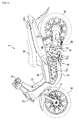
- a scooter type vehicle 1 shown in FIG. 1 is used to explain a preferred embodiment of the invention.
- the "motorcycle” is not limited to a scooter type vehicle.
- the term “motorcycle” indicates a motorcycle defined in a broad sense. More specifically, in the specification, the term “motorcycle” indicates any vehicle that changes direction by banking the vehicle. At least one of the front wheel and the rear wheel may include a plurality of wheels. More specifically, the “motorcycle” may be a vehicle in which at least one of the front wheel and the rear wheel includes two wheels that are arranged adjacent to each other. Examples of the "motorcycle” include, at least, a motorcycle defined in a narrow sense, a scooter type vehicle, a moped type vehicle, and an off-road vehicle.
- the terms front and rear, and left and right as used in the following description indicate the front and rear and the left and right as viewed by a rider seated on a seat 14 of the scooter type vehicle 1.
- the scooter type vehicle 1 includes a body frame 10.
- the body frame 10 includes a head pipe (not shown).
- the head pipe extends downward from the front part of the vehicle to the front side in a slightly inclined direction.
- a steering shaft (not shown) is rotatably inserted in the head pipe.
- the upper end portion of the steering shaft is provided with a handle 12. Meanwhile, the lower end portion of the steering shaft is connected to a front fork 15.
- the lower end portion of the front fork 15 is rotatably attached with a front wheel 16 as a driven wheel.
- a body cover 13 is attached to the body frame 10.
- the body cover 13 covers a part of the body frame 10.
- the body cover 13 includes a leg shield 27.
- the leg shield 27 covers the front of the vehicle.
- the body cover 13 is disposed to the rear of the leg shield 27, and includes foot rests 17 that are provided on the left and right sides of the vehicle. Foot rest surfaces 17a are formed on the foot rests 17. The rider's feet are placed on the foot rest surfaces 17a.
- a center cover 26 that is a part of the body cover 13 is provided between the left and right foot rests 17.
- the center cover 26 protrudes upward from the foot rest surfaces 17a of the foot rests 17, and is formed in a tunnel shape extending in the front-rear direction.
- the seat 14 on which the rider sits is attached to a section of the body cover 13 located to the rear of the center cover 26.
- a side stand 23 is attached to the body frame 10 substantially at the center of the vehicle.
- An engine unit 20 is swingably suspended from the body frame 10. More specifically, the engine unit 20 is a swing unit type engine. An engine bracket 21 is integrally connected to the engine unit 20. The engine unit 20 is swingably attached to a pivot shaft 19 of the body frame 10 via the engine bracket 21. Further, one end of a cushion unit 22 is attached to the engine unit 20. The other end of the cushion unit 22 is attached to the rear of the body frame 10. The swinging movement of the engine unit 20 is suppressed by the cushion unit 22.
- the engine unit 20 includes an output shaft 33 (refer to FIG. 2 ) that outputs power generated in the engine unit 20.
- a rear wheel 18 is attached to the output shaft 33. Accordingly, the rear wheel 18 is driven by the power generated in the engine unit 20. That is, the rear wheel 18 is a driving wheel in the first embodiment.
- a vehicle speed sensor 88 is provided on the output shaft 33. More specifically, the vehicle speed sensor 88 is provided on a fourteenth gear 80 that rotates together with the output shaft 33. Note that the vehicle speed sensor 88 may be provided on a rotation shaft other than the output shaft 33, and may be provided on another member that rotates at a certain rotation speed ratio with respect to the output shaft 33.
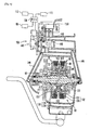
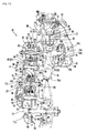
- FIG. 2 is a cross sectional view of the engine unit 20.
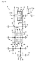
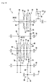
- FIG. 4 is a schematic diagram showing the structure of the engine unit 20.
- the engine unit 20 includes an engine 30 and a transmission 31. Note that, in the first embodiment, an example is described in which the engine 30 is a single cylinder engine. However, in the invention, the engine 30 is not limited to a single cylinder engine.
- the engine 30 may be a multi-cylinder engine, such as a two cylinder engine.
- the engine 30 includes a crank case 32, a cylinder body 37, a cylinder head 40, and a crank shaft 34.
- a crank chamber 35 is formed within and defined by the crank case 32.
- a cylinder 38 that opens into the crank chamber 35 is formed within and defined by the cylinder body 37.
- the cylinder head 40 is attached to the upper end of the cylinder body 37.
- the crank shaft 34 that extends in the vehicle width direction is disposed in the crank chamber 35.
- a connecting rod 36 is attached to the crank shaft 34.
- a piston 39 disposed in the cylinder 38 is attached to the tip end of the connecting rod 36.
- a combustion chamber 41 is defined by the piston 39, the cylinder body 37, and the cylinder head 40.
- a spark plug 42 is attached to the cylinder head 40 such that an ignition section at the tip end of the spark plug 42 is located in the combustion chamber 41.
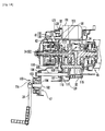
- FIG. 3 is a partial cross sectional view of the engine unit 20, which shows a kick starter 100 and a starter 101. As shown in FIG. 1 and FIG. 3 , the engine unit 20 is provided with the kick starter 100. The rider of the scooter type vehicle 1 operates the kick starter 100 to start the engine 30.
- the kick starter 100 includes a kick pedal 24.
- the kick pedal 24 is provided to the rear of and above the crank shaft 34, on the left side of the crank case 32.
- the kick pedal 24 is attached to a kick shaft 102.
- a compression coil spring 103 is provided between the kick shaft 102 and the crank case 32.
- the compression coil spring 103 applies, to the kick shaft 102 rotated by the rider ' s operation, an urging force in a reverse rotating direction.
- a gear 104 is provided on the kick shaft 102.
- a gear 106 is provided such that it cannot rotate with respect to a shaft 105.
- the gear 104 meshes with the gear 106. Rotation of the kick shaft 102 is transmitted to the crank shaft 34 by the gear 104 etc.
- a ratchet 107 is formed on the shaft 105.
- a ratchet 108 is attached to a section of the shaft 105 where the ratchet 107 is formed.
- the ratchet 108 is guided by the ratchet 107, and moves to the right in the axial direction of the shaft 105.
- the ratchet 108 is guided by the ratchet 107, and moves to the left in the axial direction of the shaft 105.
- An engagement section 109 is formed on the right end face of the ratchet 108.
- an engagement section 110 is formed on the left end face of a gear 111 rotatably provided on the shaft 105.
- the engagement section 109 of the ratchet 108 engages with the engagement section 110 when the ratchet 108 moves to the right.
- rotation of the shaft 105 is transmitted to the gear 111.
- the gear 111 meshes with a gear 116 formed on a balancer shaft 115.
- a gear 129 is provided on the balancer shaft 115.
- the gear 129 rotates together with the balancer shaft 115.
- the gear 129 meshes with a gear 117 formed on the crank shaft 34.
- rotation of the gear 111 is transmitted to the crank shaft 34 via the balancer shaft 115. Accordingly, when the kick pedal 24 is operated, the crank shaft 34 rotates and the engine 30 is started.
- the kick shaft 102 extends toward the center of the vehicle such that it straddles the transmission 31. That is, as shown in FIG. 3 , the kick shaft 102 extends from the left side in the vehicle width direction toward the center of the vehicle, and is disposed such that the kick shaft 102 is aligned with a section of the transmission 31 in the up-down direction.
- the starter 101 is also provided in the engine 30.
- the starter 101 is attached to the crank case 32.
- the rotation of the starter 101 is transmitted to the crank shaft 34 via gears 120, 121, and 122.
- the starter 101 is driven by the rider's operation, the engine 30 is started.
- a generator cover 43 is attached to the right side of the crank case 32.
- a generator housing 44 is defined by the generator cover 43 and the crank case 32.
- the right end of the crank shaft 34 protrudes from the crank chamber 35 and reaches the generator housing 44.
- the generator 45 is attached to the right end of the crank shaft 34.
- the generator 45 includes an inner 45a and an outer 45b.
- the inner 45a is attached such that it cannot rotate with respect to the crank case 32.
- the outer 45b is attached to the right end of the crank shaft 34.
- the outer 45b rotates together with the crank shaft 34. Accordingly, when the crank shaft 34 rotates, the outer 45b rotates relatively to the inner 45a. Thus, power is generated.
- a fan 46 is provided on the outer 45b. The fan 46 rotates together with the crank shaft 34, thereby cooling the engine 30.
- a transmission cover 50 is attached to the left side of the crank case 32.
- the transmission cover 50 and the crank case 32 define a transmission housing 51 located on the left side of the crank case 32.
- the transmission 31 is a four-speed stepped automatic transmission that includes an input shaft 52 and the output shaft 33.
- the transmission 31 is a gear train stepped transmission in which power is transmitted from the input shaft 52 to the output shaft 33 via a plurality of pairs of shift gears.
- crank shaft 34 protrudes from the crank chamber 35, and reaches the transmission housing 51.
- the crank shaft 34 also serves as the input shaft 52 of the transmission 31.
- the transmission 31 has a first rotation shaft 53, a second rotation shaft 54, a third rotation shaft 64, and the output shaft 33.
- the first rotation shaft 53, the second rotation shaft 54, the third rotation shaft 64, and the output shaft 33 are respectively provided in parallel with the input shaft 52.
- the reference numerals C1, C2, C3, C4, and C5 respectively represent the axis of the input shaft 52, the axis of the first rotation shaft 53, the axis of the second rotation shaft 54, the axis of the third rotation shaft 64, and the axis of the output shaft 33.
- the input shaft 52, the first rotation shaft 53, the second rotation shaft 54, the third rotation shaft 64, and the output shaft 33 are arranged in a generally horizontal direction orthogonal to the axial direction of the input shaft 52.
- the axis C1 of the input shaft 52, the axis C2 of the first rotation shaft 53, the axis C3 of the second rotation shaft 54, the axis C4 of the third rotation shaft 64, and the axis C5 of the output shaft 33 are arranged in a generally horizontal line in a side view.
- the distance between the input shaft 52 and the output shaft 33 can be made relatively long.
- the reference numeral 94 denotes an idle gear.
- the reference numeral 95 denotes a one-way gear for the starter.
- the output shaft 33 and the third rotation shaft 64 are separately provided.
- the output shaft 33 and the third rotation shaft 64 may be the same shaft.
- the rear wheel 18 may be attached to the third rotation shaft 64.
- the input shaft 52 is provided with a group of clutches 81 on the upstream side.
- the group of clutches 81 on the upstream side includes a first clutch 55 and a second clutch 59.
- the first clutch 55 is disposed on the right side of the second clutch 59.
- the first clutch 55 and the second clutch 59 are centrifugal clutches. More specifically, in the first embodiment, the first clutch 55 and the second clutch 59 are drum type centrifugal clutches.
- the second clutch 59 may be a clutch other than a centrifugal clutch.
- the second clutch 59 may be a hydraulic clutch.
- the first clutch 55 includes an inner 56 as an input side clutch member, and an outer 57 as an output side clutch member.
- the inner 56 is provided such that it cannot rotate with respect to the input shaft 52. Accordingly, the inner 56 rotates together with the input shaft 52.
- the outer 57 can rotate with respect to the input shaft 52.
- the rotation speed of the input shaft 52 becomes higher than a predetermined rotation speed
- the inner 56 and the outer 57 come into contact due to centrifugal force acting on the inner 56.
- the first clutch 55 is engaged.
- the centrifugal force acting on the inner 56 is reduced.
- the first clutch 55 is disengaged.
- the second clutch 59 includes an inner 60 as an output side clutch member, and an outer 61 as an input side clutch member.
- the inner 60 is provided such that it cannot rotate with respect to an eleventh gear 62 to be described later.
- the rotation is transmitted to the inner 60 via a first pair of shift gears 86, the first rotation shaft 53, and a fourth pair of shift gears 83.
- the inner 60 rotates together with the rotation of the input shaft 52.
- the outer 61 can rotate with respect to the input shaft 52.
- the rotation speed of the input shaft 52 becomes higher than a predetermined rotation speed, the inner 60 and the outer 61 come into contact due to centrifugal force acting on the inner 60.
- the second clutch 59 is engaged.
- the outer 57 and the outer 61 are formed by the same member.
- the invention is not limited to this structure.
- the outer 57 and the outer 61 may be formed by separate members.
- the rotation speed of the input shaft 52 when the first clutch 55 is engaged, and the rotation speed of the input shaft 52 when the second clutch 59 is engaged are different from each other.
- the rotation speed of the inner 56 when the first clutch 55 is engaged, and the rotation speed of the inner 60 when the second clutch 59 is engaged are different from each other.
- the rotation speed of the input shaft 52 when the first clutch 55 is engaged is lower than the rotation speed of the input shaft 52 when the second clutch 59 is engaged.
- the first clutch 55 is engaged when the rotation speed of the input shaft 52 is equal to or higher than a first rotation speed.
- the first clutch 55 is disengaged when the rotation speed of the input shaft 52 is lower than the first rotation speed.
- the second clutch 59 is engaged when the rotation speed of the input shaft 52 is equal to or higher than a second rotation speed that is higher than the first rotation speed. On the other hand, the second clutch 59 is disengaged when the rotation speed of the input shaft 52 is lower than the second rotation speed.
- a first gear 58 is provided on the outer 57 of the first clutch 55 such that it cannot rotate with respect to the outer 57.
- the first gear 58 rotates together with the outer 57 of the first clutch 55.
- a second gear 63 is provided on the first rotation shaft 53.
- the second gear 63 meshes with the first gear 58.
- the first gear 58 and the second gear 63 form the first pair of shift gears 86.
- the first pair of shift gears 86 is a pair of first speed shift gears.
- the second gear 63 is a one-way gear. More specifically, the second gear 63 transmits the rotation of the first gear 58 to the first rotation shaft 53. On the other hand, the second gear 63 does not transmit the rotation of the first rotation shaft 53 to the input shaft 52. That is, the second gear 63 also serves as a one-way rotation transmission mechanism 96.
- the eleventh gear 62 is provided on the inner 60 that is an output side clutch member of the second clutch 59.
- the eleventh gear 62 rotates together with the inner 60.
- a twelfth gear 65 is provided on the first rotation shaft 53.
- the twelfth gear 65 meshes with the eleventh gear 62.
- the twelfth gear 65 and the eleventh gear 62 form the fourth pair of shift gears 83.
- the fourth pair of shift gears 83 has a gear ratio different from that of the first pair of shift gears 86. More specifically, the fourth pair of shift gears 83 has a gear ratio smaller than that of the first pair of shift gears 86.
- the fourth pair of shift gears 83 is a pair of second speed shift gears.
- the first clutch 55 and the second clutch 59 are located. In other words, the first clutch 55 and the second clutch 59 are disposed between the first pair of shift gears 86 and the fourth pair of shift gears 83.
- the twelfth gear 65 also functions as a ninth gear 87.
- the twelfth gear 65 and the ninth gear 87 are common.
- a tenth gear 75 is provided on the second rotation shaft 54 such that the tenth gear 75 cannot rotate with respect to the second rotation shaft 54.
- the tenth gear 75 rotates together with the second rotation shaft 54.
- the ninth gear 87 that also functions as the twelfth gear 65 meshes with the tenth gear 75.
- the ninth gear 87 that also functions as the twelfth gear 65 and the tenth gear 75 form a first pair of transmission gears 84.
- a seventh gear 74 is provided on the second rotation shaft 54 such that it cannot rotate with respect to the second rotation shaft 54.
- the seventh gear 74 rotates together with the second rotation shaft 54.
- an eighth gear 78 is provided on the third rotation shaft 64 such that it cannot rotate with respect to the third rotation shaft 64.
- the third rotation shaft 64 rotates together with the eighth gear 78.
- the seventh gear 74 and the eighth gear 78 mesh with each other.
- the seventh gear 74 and the eighth gear 78 form a second pair of transmission gears 85.
- the eighth gear 78 is a one-way gear. More specifically, the eighth gear 78 transmits the rotation of the second rotation shaft 54 to the third rotation shaft 64. On the other hand, the eighth gear 78 does not transmit the rotation of the third rotation shaft 64 to the second rotation shaft 54. That is, the eighth gear 78 also serves as a one-way rotation transmission mechanism 93.
- the eighth gear 78 it is not essential in the invention for the eighth gear 78 to be a one-way gear.
- a structure may be adopted in which the eighth gear 78 is a normal gear, and the seventh gear 74 is a one-way gear.
- the seventh gear 74 may also serve as a one-way rotation transmission mechanism. More specifically, a structure may be adopted in which the seventh gear 74 transmits the rotation of the second rotation shaft 54 to the eighth gear 78, but it does not transmit the rotation of the eighth gear 78 to the second rotation shaft 54.
- the second rotation shaft 54 is provided with a group of clutches 82 on the downstream side.
- the group of clutches 82 on the downstream side is located to the rear of the group of clutches 81 on the upstream side.
- the group of clutches 82 on the downstream side and the group of clutches 81 on the upstream side are disposed at locations where they at least partially overlap in the axial direction of the input shaft 52.
- the group of clutches 82 on the downstream side and the group of clutches 81 on the upstream side are disposed at locations where they at least partially overlap in the vehicle width direction.
- the group of clutches 82 on the downstream side and the group of clutches 81 on the upstream side are disposed at locations where they substantially overlap in the vehicle width direction.
- the group of clutches 82 on the downstream side includes a third clutch 70 and a fourth clutch 66.
- the fourth clutch 66 is disposed on the right side of the third clutch 70. Therefore, the direction in which the first clutch 55 is located with respect to the second clutch 59 is the same as the direction in which the fourth clutch 66 is located with respect to the third clutch 70.
- the first clutch 55 and the fourth clutch 66 are disposed so that they at least partially overlap in the vehicle width direction.
- the first clutch 55 and the fourth clutch 66 are disposed so that they at least partially overlap in the axial direction of the input shaft 52.
- the second clutch 59 and the third clutch 70 are disposed so that they at least partially overlap in the vehicle width direction.
- the second clutch 59 and the third clutch 70 are disposed so that they at least partially overlap in the axial direction of the input shaft 52.
- the first clutch 55 and the fourth clutch 66 are disposed so that they substantially overlap in the vehicle width direction.
- the second clutch 59 and the third clutch 70 are disposed so that they substantially overlap in the vehicle width direction.
- the third clutch 70 and the fourth clutch 66 are hydraulic clutches. More specifically, in the first embodiment, the third clutch 70 and the fourth clutch 66 are disc type hydraulic clutches. However, the invention is not limited to this structure.
- the fourth clutch 66 and the third clutch 70 may be clutches other than hydraulic clutches.
- the fourth clutch 66 and the third clutch 70 may be centrifugal clutches. However, it is preferable that the fourth clutch 66 and the third clutch 70 are hydraulic clutches.
- the first clutch 55 is a centrifugal clutch
- at least one of the second clutch 59, the third clutch 70 and the fourth clutch 66 may be a hydraulic clutch.
- the second clutch 59, the third clutch 70 and the fourth clutch 66 may be drum type or disc type centrifugal clutches, or may be drum type or disc type hydraulic clutches.
- the second clutch 59 to be a centrifugal clutch and for the third clutch 70 and the fourth clutch 66 to be hydraulic clutches.
- centrifugal clutch refers to a clutch that has an input side clutch member and an output side clutch member, where, when the rotation speed of the input side clutch member is equal to or higher than a predetermined rotation speed, the input side clutch member and the output side clutch member are engaged and joined, and when the rotation speed of the input side clutch member is lower than the predetermined rotation speed, the input side clutch member and the output side clutch member separate and are disengaged.
- the rotation speed of the second rotation shaft 54 when the third clutch 70 is engaged, and the rotation speed of the second rotation shaft 54 when the fourth clutch 66 is engaged are different from each other.
- the rotation speed of the inner 71 when the third clutch 70 is engaged, and the rotation speed of the inner 67 when the fourth clutch 66 is engaged are different from each other. More specifically, the rotation speed of the second rotation shaft 54 when the third clutch 70 is engaged is lower than the rotation speed of the second rotation shaft 54 when the fourth clutch 66 is engaged.
- the third clutch 70 is provided with the inner 71 as an input side clutch member, and an outer 72 as an output side clutch member.
- the inner 71 is provided such that it cannot rotate with respect to the second rotation shaft 54. Accordingly, the inner 71 rotates together with the rotation of the second rotation shaft 54.
- the outer 72 can rotate with respect to the second rotation shaft 54.
- the third clutch 70 is disengaged, when the second rotation shaft 54 rotates, the inner 71 rotates together with the second rotation shaft 54, but the outer 72 does not rotate together with the second rotation shaft 54.
- both the inner 71 and the outer 72 rotate together with the second rotation shaft 54.
- a fifth gear 73 is attached to the outer 72 that is an output side clutch member of the third clutch 70.
- the fifth gear 73 rotates together with the outer 72.
- a sixth gear 77 is provided on the third rotation shaft 64 such that it cannot rotate with respect to the third rotation shaft 64.
- the sixth gear 77 rotates together with the third rotation shaft 64.
- the fifth gear 73 and the sixth gear 77 mesh with each other. Therefore, the rotation of the outer 72 is transmitted to the third rotation shaft 64 via the fifth gear 73 and the sixth gear 77.
- the fifth gear 73 and the sixth gear 77 form a third pair of shift gears 91.
- the third pair of shift gears 91 has a gear ratio that is different from the ratios of the first pair of shift gears 86, the fourth pair of shift gears 83, and a second pair of shift gears 90.
- the third pair of shift gears 91 is located with respect to the third clutch 70 on the same side on which the fourth pair of shift gears 83 is located with respect to the second clutch 59. More specifically, the third pair of shift gears 91 is located on the left side of the third clutch 70. In a similar manner, the fourth pair of shift gears 83 is located on the left side of the second clutch 59.
- the third pair of shift gears 91 and the fourth pair of shift gears 83 are disposed so that they at least partially overlap with each other in the vehicle width direction.
- the third pair of shift gears 91 and the fourth pair of shift gears 83 are disposed so that they at least partially overlap with each other in the axial direction of the input shaft 52. More specifically, the third pair of shift gears 91 and the fourth pair of shift gears 83 are disposed so that they substantially overlap in the vehicle width direction.
- the fourth clutch 66 is provided with the inner 67 as an input side clutch member and an outer 68 as an output side clutch member.
- the inner 67 is provided such that it cannot rotate with respect to the second rotation shaft 54. Accordingly, the inner 67 rotates together with the rotation of the second rotation shaft 54.
- the outer 68 can rotate with respect to the second rotation shaft 54. In a state where the fourth clutch 66 is disengaged, when the second rotation shaft 54 rotates, the inner 67 rotates together with the second rotation shaft 54, but the outer 68 does not rotate together with the second rotation shaft 54. In a state where the fourth clutch 66 is engaged, both the inner 67 and the outer 68 rotate together with the second rotation shaft 54.
- a third gear 69 is attached to the outer 68 that is an output side clutch member of the fourth clutch 66.
- the third gear 69 rotates together with the outer 68.
- a fourth gear 76 is provided on the third rotation shaft 64 such that it cannot rotate with respect to the third rotation shaft 64.
- the fourth gear 76 rotates together with the third rotation shaft 64.
- the third gear 69 and the fourth gear 76 mesh with each other. Therefore, the rotation of the outer 68 is transmitted to the third rotation shaft 64 via the third gear 69 and the fourth gear 76.
- the fourth gear 76 and the third gear 69 form the second pair of shift gears 90.
- the second pair of shift gears 90 has a gear ratio that is different from the ratios of the first pair of shift gears 86 and the fourth pair of shift gears 83.
- the third clutch 70 and the fourth clutch 66 are located. In other words, the third clutch 70 and the fourth clutch 66 are disposed between the third pair of shift gears 91 and the second pair of shift gears 90.
- the second pair of shift gears 90 is located with respect to the fourth clutch 66 on the same side on which the first pair of shift gears 86 is located with respect to the first clutch 55. More specifically, the second pair of shift gears 90 is located on the right side of the fourth clutch 66. In a similar manner, the first pair of shift gears 86 is located on the right side of the first clutch 55.
- the second pair of shift gears 90 and the first pair of shift gears 86 are disposed so that they at least partially overlap with each other in the vehicle width direction.
- the second pair of shift gears 90 and the first pair of shift gears 86 are disposed so that they at least partially overlap with each other in the axial direction of the input shaft 52. More specifically, the second pair of shift gears 90 and the first pair of shift gears 86 are disposed so that they substantially overlap in the vehicle width direction.
- a thirteenth gear 79 is provided on the third rotation shaft 64 such that it cannot rotate with respect to the third rotation shaft 64.
- the thirteenth gear 79 is disposed on the left side of the fourth gear 76 and the sixth gear 77, in the vehicle width direction.
- the thirteenth gear 79 rotates together with the third rotation shaft 64.
- the fourteenth gear 80 is provided on the output shaft 33 such that it cannot rotate with respect to the output shaft 33. In other words, the fourteenth gear 80 rotates together with the output shaft 33.
- the fourteenth gear 80 and the thirteenth gear 79 form a third pair of transmission gears 98.
- the third pair of transmission gears 98 transmits the rotation of the third rotation shaft 64 to the output shaft 33.
- the third clutch 70 is provided with a plate group 136.
- the plate group 136 includes a plurality of friction plates 134 and a plurality of clutch plates 135.
- the plurality of friction plates 134 and the plurality of clutch plates 135 are alternately laminated in the vehicle width direction.
- the friction plates 134 are unrotatable with respect to the outer 72.
- the clutch plates 135 are unrotatable with respect to the inner 71.
- the inner 71 is rotatable with respect to the outer 72.
- a pressure plate 163 is disposed on the side of the inner 71 opposite to the outer 72 in the vehicle width direction.
- the pressure plate 163 is urged rightward in the vehicle width direction by a compression coil spring 92. That is, the pressure plate 163 is urged to a boss portion 162 by the compression coil spring 92.
- a working chamber 137 is defined between the boss portion 162 and the pressure plate 163.
- the working chamber 137 is filled with oil.
- a hydraulic pressure within the working chamber 137 increases, the pressure plate 163 is displaced in a direction away from the boss portion 162. Accordingly, a distance between the pressure plate 163 and the inner 71 becomes short. Accordingly, the plate group 136 mutually becomes in a press-contact state. As a result, the inner 71 and the outer 72 rotate together, and the third clutch 70 becomes in an engagement state.
- a tiny leak hole that communicates with the working chamber 137 is formed in the third clutch 70. Further, a gap between the inner 71 and the outer 72 is not sealed. Thus, the oil in the working chamber 137 can be rapidly discharged when the clutch 70 is disengaged. Therefore, according to the embodiment, the response of the clutch 70 can be improved. In addition, according to the embodiment, the oil scattering from the leak hole or the gap between the inner 71 and the outer 72 can be used to lubricate other sliding sections effectively.
- the fourth clutch 66 is provided with a plate group 132.
- the plate group 132 includes a plurality of friction plates 130 and a plurality of clutch plates 131.
- the plurality of friction plates 130 and the plurality of clutch plates 131 are alternately laminated in the vehicle width direction.
- the friction plates 130 are unrotatable with respect to the outer 68.
- the clutch plates 131 are unrotatable with respect to the inner 67.
- the inner 67 is rotatable with respect to the outer 68 and is displaceable in the vehicle width direction.
- a pressure plate 161 is disposed on the side of the inner 67 opposite to the outer 68 in the vehicle width direction.
- the pressure plate 161 is urged leftward in the vehicle width direction by a compression coil spring 89. That is, the pressure plate 161 is urged to the boss portion 162 by the compression coil spring 89.
- a working chamber 133 is defined between the boss portion 162 and the pressure plate 161.
- the working chamber 133 is filled with oil.
- the pressure plate 161 is displaced in a direction away from the boss portion 162. Accordingly, a distance between the pressure plate 161 and the inner 67 becomes short. Accordingly, the plate group 132 mutually becomes in a pressure-contact state. As a result, the inner 67 and the outer 68 rotate together, and the fourth clutch 66 becomes in an engagement state.
- a tiny leak hole that communicates with the working chamber 133 is formed in the fourth clutch 66. Further, a gap between the inner 67 and the outer 68 is not sealed. Thus, the oil in the working chamber 133 can be rapidly discharged when the clutch 66 is disengaged. Therefore, according to the embodiment, the response of the clutch 66 can be improved. In addition, according to the embodiment, the oil scattering from the leak hole or the gap between the inner 67 and the outer 68 can be used to lubricate other sliding sections effectively.
- an oil pump 140 applies and regulates the pressure in the working chamber 133 of the fourth clutch 66 and the pressure in the working chamber 137 of the third clutch 70.
- an oil reservoir 99 is formed at the bottom of the crank chamber 35.
- a strainer 141 which is also shown in FIG. 8 , is immersed in the oil reservoir 99.
- the strainer 141 is connected to the oil pump 140. When the oil pump 140 is driven, the oil accumulated in the oil reservoir 99 is pumped up via the strainer 141.
- a relief valve 147 is provided in the middle of a first oil path 144.
- the pumped oil is purified by an oil cleaner 142, and is regulated to a predetermined pressure by the relief valve 147. After that, a part of the purified oil is supplied to the crank shaft 34 and to a sliding section in the cylinder head 40. Further, a part of the purified oil is also supplied to the working chamber 133 of the fourth clutch 66 and the working chamber 137 of the third clutch 70. More specifically, a second oil path 145 and a third oil path 146 are connected to the first oil path 144 that extends from the oil cleaner 142. The second oil path 145 extends from a valve 143, and passes on the crank case 32 side.
- the second oil path 145 reaches the working chamber 133. Accordingly, the oil is supplied to the working chamber 133 via the second oil path 145, and the pressure in the working chamber 133 is regulated.
- the third oil path 146 extends from the valve 143 and passes on the transmission cover 50 side. Then, from the left end of the second rotation shaft 54, it extends through the inside of the second rotation shaft 54. Then, the third oil path 146 reaches the working chamber 137. Accordingly, the oil is supplied to the working chamber 137 via the third oil path 146.
- the valve 143 is provided at the connecting section of the first oil path 144, the second oil path 145, and the third oil path 146.
- the valve 143 opens and closes between the first oil path 144 and the third oil path 146, and between the first oil path 144 and the second oil path 145.
- a motor 150 that drives the valve 143 is attached to the valve 143.
- the motor 150 drives the valve 143, whereby the third clutch 70 and the fourth clutch 66 are engaged/disengaged. That is, in this embodiment, the oil pump 140, the valve 143, and the motor 150 form an actuator 103 that applies hydraulic pressure to the third clutch 70 and the fourth clutch 66 that are hydraulic clutches.
- the actuator 103 is controlled by an ECU 138 shown in FIG. 6 , and used to turn the third clutch 70 and the fourth clutch 66 ON/OFF. More specifically, the actuator 103 applies hydraulic pressure to the working chamber 133 and the working chamber 137 as necessary, thus engaging/disengaging the third clutch 70 and the fourth clutch 66.
- a throttle opening degree sensor 112 and the vehicle speed sensor 88 are connected to the ECU 138.
- the ECU 138 serving as a control portion controls the actuator 103 based on at least one of the throttle opening degree detected by the throttle opening degree sensor 112 and the vehicle speed detected by the vehicle speed sensor 88. By controlling the actuator 103 in this way, the ECU 138 controls the timing at which the third clutch 70 and the fourth clutch 66 are engaged.
- the ECU 138 serving as the control portion controls the actuator 103 based on both the throttle opening degree detected by the throttle opening degree sensor 112 and the vehicle speed detected by the vehicle speed sensor 88. More specifically, the ECU 138 controls the actuator 103 based on information that is obtained by applying the throttle opening degree output from the throttle opening degree sensor 112 and the vehicle speed output from the vehicle speed sensor 88 to a V-N diagram read from a memory 113.
- valve 143 is formed in a generally cylindrical shape.
- An internal path 148 for connecting the first oil path 144 and the second oil path 145, and an internal path 149 for connecting the first oil path 144 and the third oil path 146 are formed in the valve 143.
- the internal paths 148 and 149 are designed to select one of the following positions when the valve 143 is rotated by the motor 150: a position where the first oil path 144 and the second oil path 145 are connected, while the first oil path 144 and the third oil path 146 are disconnected; a position where the first oil path 144 and the third oil path 146 are connected, while the first oil path 144 and the second oil path 145 are disconnected; and a position where the first oil path 144 and the third oil path 146 are disconnected, and the first oil path 144 and the second oil path 145 are also disconnected.
- one of the following states is selected: a state where both the fourth clutch 66 and the third clutch 70 are disengaged; a state where the fourth clutch 66 is engaged, while the third clutch 70 is disengaged; and a state where the fourth clutch 66 is disengaged, while the third clutch 70 is engaged.
- the crank shaft 34 i.e., the input shaft 52
- the inner 56 of the first clutch 55 rotates together with the input shaft 52. Therefore, when the rotation speed of the input shaft 52 becomes equal to or higher than a predetermined rotation speed (i.e., the first rotation speed), and a centrifugal force equal to or larger than a predetermined magnitude is applied to the inner 56, the first clutch 55 is engaged as shown in FIG. 9 .
- the first clutch 55 When the first clutch 55 is engaged, the first pair of shift gears 86 rotates together with the outer 57 of the first clutch 55.
- the rotation of the input shaft 52 is transmitted to the first rotation shaft 53.
- the ninth gear 87 rotates together with the first rotation shaft 53. Accordingly, the first pair of transmission gears 84 also rotates along with the rotation of the first rotation shaft 53. Thus, the rotation of the first rotation shaft 53 is transmitted to the second rotation shaft 54 via the first pair of transmission gears 84.
- the seventh gear 74 rotates together with the second rotation shaft 54. Accordingly, the second pair of transmission gears 85 also rotates along with the rotation of the second rotation shaft 54. Thus, the rotation of the second rotation shaft 54 is transmitted to the third rotation shaft 64 via the second pair of transmission gears 85.
- the thirteenth gear 79 rotates together with the third rotation shaft 64. Accordingly, the third pair of transmission gears 98 also rotates along with the rotation of the third rotation shaft 64. Thus, the rotation of the third rotation shaft 64 is transmitted to the output shaft 33 via the third pair of transmission gears 98.
- the twelfth gear 65 common with the ninth gear 87 rotates together with the first rotation shaft 53. Therefore, the eleventh gear 62 meshing with the twelfth gear 65 and the inner 60 of the second clutch 59 also rotate together. Accordingly, as the rotation speed of the input shaft 52 increases, the rotation speed of the inner 60 of the second clutch 59 also increases. When the rotation speed of the input shaft 52 becomes equal to or higher than the second rotation speed that is higher than the first rotation speed, the rotation speed of the inner 60 also increases accordingly, and the second clutch 59 is engaged as shown in FIG. 10 .
- the gear ratio of the fourth pair of shift gears 83 is smaller than the gear ratio of the first pair of shift gears 86.
- the rotation speed of the twelfth gear 65 is higher than the rotation speed of the second gear 63. Accordingly, rotation is transmitted from the input shaft 52 to the first rotation shaft 53 via the fourth pair of shift gears 83.
- the rotation of the first rotation shaft 53 is not transmitted to the input shaft 52 by the one-way rotation transmission mechanism 96.
- the rotation force is transmitted from the first rotation shaft 53 to the output shaft 33, in the same manner as in the first speed, via the first pair of transmission gears 84, the second pair of transmission gears 85, and the third pair of transmission gears 98.
- the rotation of the third rotation shaft 64 is transmitted to the output shaft 33 via the third pair of transmission gears 98, in the same manner as in the first speed and the second speed.
- the valve 143 is driven and the fourth clutch 66 is engaged as shown in FIG. 12 .
- the third clutch 70 is disengaged.
- the second pair of shift gears 90 starts to rotate.
- the gear ratio of the second pair of shift gears 90 is also smaller than the gear ratio of the second pair of transmission gears 85. Therefore, the rotation speed of the fourth gear 76 of the second pair of shift gears 90 becomes higher than the rotation speed of the eighth gear 78 of the second pair of transmission gears 85.
- the rotation of the second rotation shaft 54 is transmitted to the third rotation shaft 64 via the second pair of shift gears 90.
- the rotation of the third rotation shaft 64 is not transmitted to the second rotation shaft 54 by the one-way rotation transmission mechanism 93.
- the rotation of the third rotation shaft 64 is transmitted to the output shaft 33 via the third pair of transmission gears 98, in the same manner as in the first speed to the third speed.
- the crank shaft 34 includes a pair of crank webs 34a and 34b.
- the connecting rod 36 is connected to the pair of crank webs 34a and 34b via a crank pin 34c.
- the rear wheel 18 is disposed in rear of the crank shaft 34 and on the inside of the transmission 31 in the vehicle width direction. As shown in FIG. 13 , the rear wheel 18 is disposed in rear of the crank webs 34a and 34b and the crank pin 34c. The left end of the rear wheel 18 is located on the outside of the left end of the crank pin 34c in the vehicle width direction. That is, at least a part of the rear wheel 18 is located on the outside of the crank pin 34c in the vehicle width direction.
- the engine unit 20 includes the crank case 32, the transmission cover 50, and the generator cover 43.
- the crank case 32, the transmission cover 50, and the generator cover 43 form a casing 11 for accommodating the engine 30 and the transmission 31.
- a part of the transmission cover 50 and the crank case 32 forms a transmission accommodation part 11a.
- the transmission housing 51 is formed by the transmission accommodation part 11a.
- the transmission cover 50 located on the outside of the transmission 31 in the vehicle width direction forms an outer wall 11c of the transmission accommodation part 11a.
- crank case 32 a part corresponding to the inside of the transmission 31 in the vehicle width direction and located on the outside of the rear wheel 18 in the vehicle width direction forms an inner wall 11d of the transmission accommodation part 11a.
- the first, second, and third rotation shafts 53, 54, and 64 are located between the inner wall 11d and the outer wall 11c in the vehicle width direction.
- at least a part of the second gear 63 as the second shift gear is located on the outside of the inner wall 11d in the vehicle width direction.
- a whole part of the second gear 63 is located on the outside of the inner wall 11d in the vehicle width direction.
- the crank shaft 34 is located in front of the inner wall 11d.
- the above-described kick shaft 102 is rotatably supported to the outer wall 11c.
- the balancer shaft 115 and the shaft 105 as the intermediate shaft are provided between the kick shaft 102 and the crank shaft 34.
- the gear 104 as the first kick gear provided in the kick shaft 102 is located on the outside of the first pair of shift gears 86 as the first pair of gears and the fourth pair of shift gears 83 as the second pair of gears in the vehicle width direction.
- the gear 104 meshes with the gear 106 as the second kick gear provided in the shaft 105.
- the gear 106 and the gear 104 form a pair of kick-transmission gears 47.
- the shaft 105 as the intermediate shaft is provided with a gear 111 as a third kick gear.
- the gear 111 is located on the inside of the first gear 58 in the vehicle width direction.
- the gear 111 indirectly meshes with a gear 117 as a sixth kick gear provided in the crank shaft 34.
- the gear 117 is located on the inside of the first gear 58 as the first shift gear in the vehicle width direction. That is, the gear 111 as the third kick gear indirectly meshes with a portion on the inside of the first gear 58 of the crank shaft 34 in the vehicle width direction.
- the balancer shaft 115 as an additional intermediate shaft is provided between the shaft 105 and the crank shaft 34.
- the balancer shaft 115 is provided with the gear 116 as the fourth kick gear.
- the gear 116 rotates together with the balancer shaft 115.
- the gear 116 as the fourth kick gear meshes with the gear 111 as the third kick gear.
- the balancer shaft 115 as the additional intermediate shaft is provided with the gear 129 as a fifth kick gear.
- the gear 129 rotates together with the balancer shaft 115.
- the gear 129 meshes with the gear 117 as a sixth kick gear rotating together with the crank shaft 34.
- the balancer shaft 115 is used as one of the intermediate shaft provided between the kick shaft 102 and the crank shaft 34.
- the intermediate shaft provided between the kick shaft 102 and the crank shaft 34 may be provided in addition to the balancer shaft 115.
- a gear 120 as a starter gear meshes with a portion on the inside of the first gear 58 as the first shift gear of the crank shaft 34 in the vehicle width direction.
- the gear 120 as the starter gear meshes with the gear 121 provided in a shaft 151.
- the gear 121 is rotatably fixed to the shaft 151 unrotatably fixed to the crank case 32.
- the gear 121 meshes with the gear 123.
- the gear 123 is provided on the inside part of the first gear 58 of the crank shaft 34 in the vehicle width direction.
- a power transmission mechanism 29 for transmitting the rotation of the first rotation shaft 53 to the output shaft 33 is formed by the first to third pair of transmission gears 84, 85, and 98, the downstream clutch group 82, and the second and third pair of shift gears 90 and 91.
- the first shift gear the first gear 58
- the second shift gear the second gear 63
- the third shift gear the eleventh gear 62
- the fourth shift gear the twelfth gear 65
- the first pair of gears the first pair of shift gears 86
- the second pair of gears the fourth pair of shift gears 83
- the first kick gear the gear 104
- the second kick gear the gear 106
- the third kick gear the gear 111
- the fourth kick gear the gear 116
- the fifth kick gear the gear 129
- the sixth kick gear the gear 117
- the starter gear the gear 120
- a planetary gear having a complex configuration is not used. Accordingly, the transmission 31 further realizes a simplification of the configuration of the engine unit 20.
- crank shaft 34 since a comparatively large planetary gear is not disposed on the crank shaft 34, it is possible to realize downsizing of the engine unit 20 in an axial direction of the crank shaft 34.
- a decrease in weight corresponds to a general problem to be solved. Therefore, in order to realize a decrease in weight of the engine unit, the length of the kick shaft and the intermediate shaft disposed between the kick shaft and the crank shaft tends to be very short. Specifically, for example, since the power transmission of the kick shaft and the crank shaft is carried out on the outside of the first and second pairs of shift gears in the vehicle width direction, in general, the axial length of the kick shaft and the intermediate shaft is set to be short.
- the first gear 58 and the eleventh gear 62 disposed on the input shaft 52 are rotatable with respect to the crank shaft 34. For this reason, when the power transmission of the kick shaft and the crank shaft is carried out on the outside of the first and second pairs of shift gears in the vehicle width direction, it is necessary to additionally provide a kick starter gear on the outside of the eleventh gear in the vehicle width direction. Accordingly, since the additional gear is required, the size of the engine unit in the vehicle width direction tends to increase.
- the inner 56 of the first clutch 55 rotates together with the crank shaft 34.
- the inner 56 is located between the first gear 58 as the first shift gear and the eleventh gear 62 as the third shift gear in the vehicle width direction.
- the kick starter gear is provided on the inner of the first clutch, it is necessary to make long a distance between the first gear and the eleventh gear. Accordingly, even in this case, the size of the engine unit in the vehicle width direction tends to increase.
- the inner wall 11d is comparatively disposed on the outside in the vehicle width direction in order to avoid the positional interference with the rear wheel 18. For this reason, it is necessary to dispose the first pair of shift gears 86 in the comparatively outside in the vehicle width direction. As a result, the distance between the crank pin 34c and the first gear 58 forming a part of the pair of the first shift gears 86 becomes comparatively longer.
- the gap between the first gear 58 and the crank pin 34c tends to increase particularly in a single cylinder engine or a V twin engine.
- the configuration of this embodiment is particularly effective in the engine unit having the single cylinder engine or the V twin engine.
- the intermediate shaft is not disposed between the kick shaft and the crank shaft.
- it is necessary to make large the diameter of the gear provided in the kick shaft in order to ensure a large deceleration ratio between the kick shaft and the crank shaft, it is necessary to make large the diameter of the gear provided in the kick shaft. Accordingly, a problem arises in that the gear provided in the kick shaft interferes with other members in position, and thus the size of the engine unit tends to increase.
- the shaft 105 and the balancer shaft 115 are provided between the kick shaft 102 and the crank shaft 34.
- the plurality of gears 106, 111, 116, and 129 is provided between the gear 104 provided in the kick shaft 102 and the gear 117 provided in the crank shaft 34. For this reason, it is possible to make large the deceleration ratio between the kick shaft and the crank shaft without making large each diameter of the gears 117, 106, 111, 116, and 129. Accordingly, it is possible to realize a decrease in size of the engine unit 20.
- the balancer shaft 115 is used as the intermediate shaft between the kick shaft 102 and the crank shaft 34. Accordingly, it is possible to more decrease the weight and the size of the engine unit 20 than a case in which the intermediate shaft is provided in addition to the balancer shaft 115.
- the starter 101 as well as the kick start 100. Then, the gear 120 of the starter 101 indirectly meshes with the gear 123 disposed in a dead space located on the inside of the first gear 58 in the vehicle width direction. With such a configuration, in the engine unit 20 having both the kick starter 100 and the starter 101, it is possible to realize a decrease in size in the vehicle width direction.
- the third clutch 70 and the fourth clutch 66 are configured as a hydraulic clutch. For this reason, in the third clutch 70 and the fourth clutch 66, it is possible to comparatively promptly perform the intermittence of the clutch. In other words, in the intermittence of the clutch, the third clutch 70 or the fourth clutch 66 does not continuously slide for a comparatively long time. For this reason, the energy loss in the third clutch 70 and the fourth clutch 66 reduces comparatively. Accordingly, it is possible to improve the fuel efficiency of the scooter type vehicle 1.
- the first clutch 55 and the second clutch 59 are configured as a hydraulic clutch as well as the third clutch 70 and the fourth clutch 66.
- the intermittence is comparatively promptly carried out.
- the first clutch 55 is configured as the hydraulic clutch, the first clutch 55 is suddenly engaged at a start time.
- it is difficult to perform a smooth start Accordingly, it is not possible to obtain both of the smooth start and the improvement of the fuel efficiency.
- the first clutch 55 provided for the first pair of first speed shift gears 86 is the centrifugal clutch.
- the intermittence of the clutch of the centrifugal clutch is slower than that of the hydraulic clutch.
- the smooth start of the vehicle is realized. That is, when the first clutch 55 for the first pair of first speed shift gears 86 is configured as the centrifugal clutch, and at least one of the clutches for the pair of higher-speed shift gears is configured as the hydraulic clutch, it is possible to improve the fuel efficiency and to perform the smooth start.
- the second clutch 59 is configured as the centrifugal clutch.
- the sliding does not continuously occur for a long time. Additionally, the frequency of the first speed and second speed driving is comparatively less. That is, the ratio of the first and second speed driving time in the entire driving time is comparatively small. Accordingly, even when the first clutch 55 or the second clutch 59 is configured as the centrifugal clutch, the fuel efficiency does not decrease.
- the other clutches may be configured as the hydraulic clutch in a state where only the first clutch 55 is configured as the centrifugal clutch.
- the first clutch 55 is configured as the centrifugal clutch, the engagement state of the first clutch 55 is properly changed in accordance with an acceleration of the vehicle, a vehicle speed, and an operation amount of a throttle operator. For this reason, since the first clutch 55 is configured as the centrifugal clutch, it is possible to perform driving in accordance with the intension of the rider.
- the first clutch 55 is comparatively promptly engaged, thereby performing the start at a comparatively larger acceleration.
- the throttle operator is operated to be small in order that the rider performs the smooth start at the comparatively smaller acceleration
- the first clutch 55 is comparatively slowly engaged, thereby performing the smooth start at the comparatively smaller acceleration. Accordingly, it is possible to realize a high driving performance.
- the timing of the intermittence of the centrifugal clutch is determined by the rpm of the engine, but in the hydraulic clutch, the timing of the intermittence is freely controlled by an ECU 138. That is, when two or more hydraulic clutches are used, it is possible to further improve a degree of freedom of the control of the transmission 31. Specifically, on the basis of the rider's operation or the driving state, it is possible to minutely control the intermittence of the clutch. Specifically, on the basis of at least one of the throttle opening degree and the vehicle speed, it is possible to carefully control the intermittence of the clutch.
- the plurality of hydraulic clutches is used like this embodiment, it is desirable that the plurality of hydraulic clutches is disposed on the same rotation axis. Specifically, in case of this embodiment, it is desirable that the fourth clutch 66 and the third clutch 70 as the hydraulic clutches are disposed on the same second rotation shaft 54. With such an operation, it is possible to comparatively simplify an oil supply passage to the hydraulic clutch. Accordingly, it is possible to more simplify the configuration of the transmission 31.
- the rotation shaft attached with the centrifugal clutch and the rotation shaft attached with the hydraulic clutch are separately provided.
- the second clutch 59 and the first clutch 55 as the centrifugal clutches are provided in the input shaft 52
- the fourth clutch 66 and the third clutch 70 as the hydraulic clutches are provided in the second rotation shaft 54.
- the outer 57 of the first clutch 55 and the outer 61 of the second clutch 59 are formed by the same member.
- the invention is not limited to this configuration.
- the outer 57 of the first clutch 55 and the outer 61 of the second clutch 59 may be separately provided.
- the one-way rotation transmission mechanism 93 is provided for the eighth gear 78.
- the invention is not limited to this configuration.
- the one-way rotation transmission mechanism 93 may be disposed for the seventh gear 74.
- the one-way rotation transmission mechanism 96 is disposed for the second gear 63.
- the invention is not limited to this configuration.
- the one-way rotation transmission mechanism 96 may be disposed for the first gear 58.
- the transmission 31 may be a five speed or more.
- it may be supposed that two new rotation shafts are provided between the third rotation shaft 64 and the output shaft 33 and a new clutch and a pair of new shift gears are provided on the two rotation shafts.
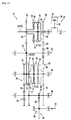
- the transmission 31 may be configured as the three-speed transmission as shown in FIG. 18 .
- the fourth clutch 66 and the second pair of shift gears 90 of the transmission 31 having a configuration shown in FIG. 4 are not provided.
- the transmission 31 may be configured as a two-speed transmission.
- the input shaft 52 and the crank shaft 34 are integrally formed with each other.
- the invention is not limited to this configuration.
- the input shaft 52 and the crank shaft 34 may be configured as different shafts. In this case, it is desirable that the axis of the input shaft 52 and the axis of the crank shaft 34 are substantially disposed on the straight line.
- the engine 30 is configured as the single cylinder engine.
- the engine 30 is not limited to the single cylinder engine.
- the engine 30 may be, for example, the multi-cylinder engine such as a two-cylinder engine.
- the output shaft 33 and the third rotation shaft 64 are separately provided.
- the invention is not limited to this configuration.
- the output shaft 33 and the third rotation shaft 64 may be common to each other.
- the rear wheel 18 may be attached to the third rotation shaft 64.
- the "motorcycle” is not limited to a motorcycle defined in a narrow sense.
- the term “motorcycle” indicates a motorcycle defined in a broad sense. More specifically, in the specification, the term “motorcycle” indicates any vehicle that changes direction by banking the vehicle.
- the term “motorcycle” indicates that at least one of the front wheel and the rear wheel may include a plurality of wheels. More specifically, the “motorcycle” may be a vehicle in which at least one of the front wheel and the rear wheel includes two wheels that are arranged adjacent to each other. Examples of the "motorcycle” include, at least, a motorcycle defined in a narrow sense, a scooter type vehicle, a moped type vehicle, and an off-road vehicle.
- centrifugal clutch refers to a clutch that has an input side clutch member and an output side clutch member, where, when the rotation speed of the input side clutch member is equal to or higher than a predetermined rotation speed, the input side clutch member and the output side clutch member are engaged and joined, and when the rotation speed of the input side clutch member is lower than the predetermined rotation speed, the input side clutch member and the output side clutch member separate and are disengaged.
- the invention is applicable to a stepped automatic transmission and a vehicle such as a motorcycle.
Landscapes
- Engineering & Computer Science (AREA)
- General Engineering & Computer Science (AREA)
- Mechanical Engineering (AREA)
- Chemical & Material Sciences (AREA)
- Combustion & Propulsion (AREA)
- Transportation (AREA)
- Physics & Mathematics (AREA)
- Fluid Mechanics (AREA)
- Structure Of Transmissions (AREA)
Applications Claiming Priority (3)
| Application Number | Priority Date | Filing Date | Title |
|---|---|---|---|
| JP2007214313 | 2007-08-21 | ||
| JP2008204931A JP4331785B2 (ja) | 2007-08-21 | 2008-08-08 | パワーユニット及びそれを備えたモーターサイクル |
| PCT/JP2008/064509 WO2009025213A1 (fr) | 2007-08-21 | 2008-08-13 | Unité motrice et moto équipée de celle-ci |
Publications (2)
| Publication Number | Publication Date |
|---|---|
| EP2151603A1 true EP2151603A1 (fr) | 2010-02-10 |
| EP2151603A4 EP2151603A4 (fr) | 2010-08-11 |
Family
ID=40378119
Family Applications (1)
| Application Number | Title | Priority Date | Filing Date |
|---|---|---|---|
| EP08827752A Withdrawn EP2151603A4 (fr) | 2007-08-21 | 2008-08-13 | Unite motrice et moto equipee de celle-ci |
Country Status (5)
| Country | Link |
|---|---|
| EP (1) | EP2151603A4 (fr) |
| JP (1) | JP4331785B2 (fr) |
| CN (1) | CN101779059A (fr) |
| BR (1) | BRPI0814810A2 (fr) |
| WO (1) | WO2009025213A1 (fr) |
Families Citing this family (5)
| Publication number | Priority date | Publication date | Assignee | Title |
|---|---|---|---|---|
| TWI408878B (zh) * | 2010-07-14 | 2013-09-11 | Kwang Yang Motor Co | Vehicle power generation device |
| JP6101578B2 (ja) * | 2013-06-25 | 2017-03-22 | 本田技研工業株式会社 | 車両の車速検出構造 |
| JP6445500B2 (ja) * | 2016-09-15 | 2018-12-26 | 株式会社エフ・シー・シー | 鞍乗り型車両 |
| CN109538710A (zh) * | 2016-11-29 | 2019-03-29 | 江苏华源节水股份有限公司 | 一种中小型喷灌机滑移换挡变速箱 |
| CN106763550B (zh) * | 2016-12-30 | 2023-09-08 | 中国第一汽车股份有限公司 | 九挡双离合器式自动变速器 |
Family Cites Families (3)
| Publication number | Priority date | Publication date | Assignee | Title |
|---|---|---|---|---|
| JPS56147946A (en) | 1980-04-21 | 1981-11-17 | Yamaha Motor Co Ltd | Speed change gear |
| JPH11280623A (ja) * | 1998-03-31 | 1999-10-15 | Honda Motor Co Ltd | パワーユニットおよび車輪の組立体 |
| JP4522944B2 (ja) * | 2005-11-30 | 2010-08-11 | 本田技研工業株式会社 | ベルト式無段変速機を備えたエンジンのキックスタータ |
-
2008
- 2008-08-08 JP JP2008204931A patent/JP4331785B2/ja not_active Expired - Fee Related
- 2008-08-13 CN CN200880025630A patent/CN101779059A/zh active Pending
- 2008-08-13 BR BRPI0814810-4A2A patent/BRPI0814810A2/pt not_active IP Right Cessation
- 2008-08-13 WO PCT/JP2008/064509 patent/WO2009025213A1/fr not_active Ceased
- 2008-08-13 EP EP08827752A patent/EP2151603A4/fr not_active Withdrawn
Non-Patent Citations (2)
| Title |
|---|
| No further relevant documents disclosed * |
| See also references of WO2009025213A1 * |
Also Published As
| Publication number | Publication date |
|---|---|
| JP4331785B2 (ja) | 2009-09-16 |
| JP2009068702A (ja) | 2009-04-02 |
| EP2151603A4 (fr) | 2010-08-11 |
| WO2009025213A1 (fr) | 2009-02-26 |
| BRPI0814810A2 (pt) | 2015-02-03 |
| CN101779059A (zh) | 2010-07-14 |
Similar Documents
| Publication | Publication Date | Title |
|---|---|---|
| EP2151603A1 (fr) | Unite motrice et moto equipee de celle-ci | |
| EP2309151B1 (fr) | Transmission automatique séquentielle pour véhicule du type chevauchement de selle, unité de commande équipée de celle-ci, et véhicule du type chevauchement de selle équipé de celle-ci | |
| EP2151602A1 (fr) | Transmission automatique étagée et véhicule équipé de celle-ci | |
| EP2151606A1 (fr) | Transmission automatique étagée, unité motrice et véhicule avec celle-ci | |
| EP2151607A1 (fr) | Transmission automatique étagée et véhicule équipé de celle-ci | |
| EP2151605B1 (fr) | Transmission automatique etagee et vehicule equipe de celle-ci | |
| EP2151600B1 (fr) | Dispositif de transmission automatique étagée et motocyclette avec celui-ci | |
| JP4327229B2 (ja) | 有段式自動変速装置、それを備えたパワーユニット、及びそれを備えたモーターサイクル | |
| JP4443365B2 (ja) | 小型車両用伝動装置 | |
| JP5513323B2 (ja) | 車両用パワーユニット | |
| JP4319694B2 (ja) | 鞍乗型車両用の有段式自動変速装置、それを備えたパワーユニット及びそれを備えた鞍乗型車両 |
Legal Events
| Date | Code | Title | Description |
|---|---|---|---|
| PUAI | Public reference made under article 153(3) epc to a published international application that has entered the european phase |
Free format text: ORIGINAL CODE: 0009012 |
|
| 17P | Request for examination filed |
Effective date: 20091207 |
|
| AK | Designated contracting states |
Kind code of ref document: A1 Designated state(s): AT BE BG CH CY CZ DE DK EE ES FI FR GB GR HR HU IE IS IT LI LT LU LV MC MT NL NO PL PT RO SE SI SK TR |
|
| AX | Request for extension of the european patent |
Extension state: AL BA MK RS |
|
| A4 | Supplementary search report drawn up and despatched |
Effective date: 20100713 |
|
| RIC1 | Information provided on ipc code assigned before grant |
Ipc: F16H 57/02 20060101ALI20100707BHEP Ipc: F16H 61/682 20060101ALI20100707BHEP Ipc: F16H 59/44 20060101ALI20100707BHEP Ipc: F16H 59/24 20060101ALI20100707BHEP Ipc: F16H 61/04 20060101ALI20100707BHEP Ipc: F16H 3/083 20060101ALI20100707BHEP Ipc: B62M 11/06 20060101ALI20100707BHEP Ipc: B62J 99/00 20090101ALI20100707BHEP Ipc: F16H 3/093 20060101AFI20091210BHEP |
|
| DAX | Request for extension of the european patent (deleted) | ||
| 17Q | First examination report despatched |
Effective date: 20110118 |
|
| GRAP | Despatch of communication of intention to grant a patent |
Free format text: ORIGINAL CODE: EPIDOSNIGR1 |
|
| RIC1 | Information provided on ipc code assigned before grant |
Ipc: F16H 57/02 20060101ALI20110802BHEP Ipc: F16H 61/682 20060101ALI20110802BHEP Ipc: F16H 59/44 20060101ALI20110802BHEP Ipc: F16H 59/24 20060101ALI20110802BHEP Ipc: F16H 61/04 20060101ALI20110802BHEP Ipc: F16H 3/083 20060101ALI20110802BHEP Ipc: B62M 11/06 20060101ALI20110802BHEP Ipc: B62J 99/00 20090101ALI20110802BHEP Ipc: F16H 3/093 20060101AFI20110802BHEP |
|
| RIN1 | Information on inventor provided before grant (corrected) |
Inventor name: HATA, SHINICHIRO C/O YAMAHA HATSUDOKI KABUSHIKI KA Inventor name: MURAYAMA, TAKUJI C/O YAMAHA HATSUDOKI KABUSHIKI KA Inventor name: OISHI, AKIFUMI C/O YAMAHA HATSUDOKI KABUSHIKI KAIS |
|
| STAA | Information on the status of an ep patent application or granted ep patent |
Free format text: STATUS: THE APPLICATION IS DEEMED TO BE WITHDRAWN |
|
| 18D | Application deemed to be withdrawn |
Effective date: 20120119 |