EP2154471B1 - Messsonde - Google Patents
Messsonde Download PDFInfo
- Publication number
- EP2154471B1 EP2154471B1 EP09015025A EP09015025A EP2154471B1 EP 2154471 B1 EP2154471 B1 EP 2154471B1 EP 09015025 A EP09015025 A EP 09015025A EP 09015025 A EP09015025 A EP 09015025A EP 2154471 B1 EP2154471 B1 EP 2154471B1
- Authority
- EP
- European Patent Office
- Prior art keywords
- probe
- stylus
- workpiece
- bendable
- section
- Prior art date
- Legal status (The legal status is an assumption and is not a legal conclusion. Google has not performed a legal analysis and makes no representation as to the accuracy of the status listed.)
- Expired - Lifetime
Links
Images


Classifications
-
- G—PHYSICS
- G01—MEASURING; TESTING
- G01B—MEASURING LENGTH, THICKNESS OR SIMILAR LINEAR DIMENSIONS; MEASURING ANGLES; MEASURING AREAS; MEASURING IRREGULARITIES OF SURFACES OR CONTOURS
- G01B7/00—Measuring arrangements characterised by the use of electric or magnetic techniques
- G01B7/004—Measuring arrangements characterised by the use of electric or magnetic techniques for measuring coordinates of points
- G01B7/008—Measuring arrangements characterised by the use of electric or magnetic techniques for measuring coordinates of points using coordinate measuring machines
- G01B7/012—Contact-making feeler heads therefor
Definitions
- the present invention relates to a measurement probe for use in determination of dimensions of articles like workpieces on positioning determining apparatus such as machine tools, coordinate measurement machines and other machines using coordinate positioning.
- the probe may include a workpiece contact element such as a stylus which is urged out of a rest state when contact with the workpiece is made. This urging can be detected and a signal indicating the said workpiece contact may be generated to provide an indication of the workpiece position according to the coordinate positioning system used.
- a workpiece contact element such as a stylus which is urged out of a rest state when contact with the workpiece is made. This urging can be detected and a signal indicating the said workpiece contact may be generated to provide an indication of the workpiece position according to the coordinate positioning system used.
- probes as described above are known. Ideally such probes should be very sensitive to force acting on the probe's stylus or other contact element, and yet be reasonably robust to prevent damage to the probe e.g. when the probe is dropped or accidentally driven into the workpiece violently.
- contact measurement probes fall into two categories: those that produce a trigger signal very quickly when workpiece contact is made (so called “touch trigger probes”); and those which have a variable signal indicative of the amount of deflection of the stylus relative to the probe body (so called “analogue probes” or “scanning probes”).
- Analogue probes are used generally in a manner such the stylus moves across the workpiece and the probe generates many data points corresponding to the profile of the workpiece. Analogue probes are necessarily sensitive and consequently are generally not suited to rugged use.
- Touch trigger probes are simpler and better suited to applications such as use on a machine tool, where adverse conditions such as knocks and vibration are encountered.
- Touch trigger probes conventionally have an electrical switch type arrangement which is opened (or closed) on workpiece contact.
- Touch trigger probes are generally mechanical in nature and have moving parts which can become worn or damaged.
- probes which employ strain gauges have been developed.
- One such probe is shown in US Patent No. 5,327,657 .
- Fig 9 of that document shows a strain gauge cell 334 which is strained in use by the stylus shown at the lower part of Fig 9.
- the cell 334 has three legs extending toward the stylus. Whilst this probe is sensitive it is not particularly robust, particularly if the stylus is knocked.
- a similar probe is shown in EP-A-0 068 899 .
- FIG. 1 Another strain gauge probe is shown in International Patent Application No. WO01/96809A1 , Fig 3 of which shows a strain gauge support structure 34 having three legs.
- Fig 3 shows a strain gauge support structure 34 having three legs.
- an additional stylus support 42 is provided. This additional support allows the strain gauge support structure 34 to be reduced in stiffness and thus made more sensitive. Overall, the probe structure is not compact.
- the inventor of the present invention has proposed a sensitive touch trigger probe which is robust which in the embodiments described herein negates the requirement for additional stylus support.
- EP 0897100 describes a probe in which a pair of piezoelectric elements are mounted on opposing sides of a bendable member having a square cross-section, so as to provide respective signals upon bending. A circuit receives these signals and processes them differentially to produce a combined output signal.
- the present invention provides a probe for position determining apparatus, comprising: a probe body, a workpiece-contacting stylus, a strain sensitive structure connecting the body and the stylus, the strain sensitive structure including at least one bendable arm member which has an axis and which is bendable relative to the axis when the stylus contacts a workpiece, a pair of strain sensing elements mounted on opposing sides of said bendable arm member, so as to provide respective signals upon bending thereof, and a circuit which receives said signals and processes them differentially to produce a combined output signal, characterised in that said at least one bendable arm member has a thin rectangular cross-section, and said pair of strain sensing elements are mounted on opposing short edges of the rectangular cross-section.
- a dimensional measurement probe 10 is shown in Fig 1 which is attachable to a machine 5 via a boss 12.
- the machine is typically one which can determine the coordinates of the probe e.g. in x, y and z planes.
- the probe has a stylus 14 including a tip 16 for contact with a workpiece or other artefact 50 to be measured.
- the probe is moved by the machine relative to the artefact 50 and contact of the stylus tip with the artefact 50 is sensed by the mechanism within the probe 10.
- the probe produces a signal which is sent to the machine in order to determine the probe's coordinates. In this way the coordinates of the surface of the artefact can be obtained.
- the probe 10 includes a main body 18, a circuit board 20, a spring cage 22, a compression spring 24, upper member 26 of stylus 14 and a strain sensing element 30.
- a circuit board 20 for clarity the view of the probe is a part-section in the sectional plane shown as 1-1 in Fig 2 . This plane is not completely flat but includes two planes at 120° to each other.
- the contact between this upper member 26 and the sensor element 30 is in the form of a kinematic location having a total of six points of contact.
- the kinematic location is formed from three balls 31 on the sensor, each one nesting between a pair of rollers 27 on the member 26.
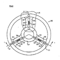
- Fig 2 shows the sensor element 30 in more detail.
- the element 30 is produced as one piece, e.g. of machined metal.
- Each of the three balls 31 affixed to the surface of the element 30 has in use force exerted on them.
- the force exerted on the balls is altered.
- This in turn causes strain to be induced in radial arms 32.
- a semiconductor strain gauge 33 is secured to each of the arms 32.
- Each strain gauge provides a change in output if the strain in the arm is altered.
- Circuit board 20 enables such detection.
- An example of a circuit suitable for use in this invention is described in US Patent No. 5,228,352 .
- Fig 3 shows an arm member 90 for use instead of the arm members 32 of Figs 1-2 . It is shown in cross-section and has a thin rectangular cross-section. Two strain gauges 33 are mounted on opposing short edges of the rectangular cross-section, and are therefore well spaced apart. The electrical outputs of the two strain gauges are taken to the positive and negative inputs of a differential amplifier 92, which combines them differentially. Because of the thin rectangular cross-section, and the differential processing, good sensitivity to bending is achieved in a reasonably robust structure.
- Fig 4 shows a variant of the arm member of Fig 3 .
- a lateral member 94 augments the rectangular cross-section 90, so that the overall cross-section is in the shape of a cross.
- the lateral member 94 increases the stiffness of the member in the region of the neutral bending axis.
- the resulting structure can be thought of as similar to two "T" shaped arm members, back-to-back.
- a kinematic support for stylus 14 is shown which acts as a safety mechanism to prevent undue strain on element 30.
- this feature is not essential or could be replaced or supplemented by another feature which operates in a similar manner.
Landscapes
- Physics & Mathematics (AREA)
- General Physics & Mathematics (AREA)
- Measurement Of Length, Angles, Or The Like Using Electric Or Magnetic Means (AREA)
- A Measuring Device Byusing Mechanical Method (AREA)
- Machine Tool Sensing Apparatuses (AREA)
- Surgical Instruments (AREA)
- Investigating Or Analysing Biological Materials (AREA)
- Cold Cathode And The Manufacture (AREA)
- Magnetic Heads (AREA)
Claims (6)
- Taster (10) für eine Positionsbestimmungsvorrichtung, umfassend:einen Tasterkörper (18),einen Werkstückkontakt-Taststift (14),einen dehnungsempfindlichen Aufbau (70), der den Körper (18) mit dem Taststift (14) verbindet, wobei der dehnungsempfindliche Aufbau (70) zumindest ein biegbares Armelement (90) aufweist, das eine Achse besitzt und das relativ zu der Achse biegbar ist, wenn der Taststift (14) mit einem Werkstück (50) in Kontakt tritt,ein Paar von Dehnungserfassungselementen (33), die an gegenüberliegenden Seiten des biegbaren Armelementes (90) montiert sind, um so beim Biegen desselben jeweilige Signale bereitzustellen, undeine Schaltung (92), die die Signale aufnimmt und diese differentiell verarbeitet, um ein kombiniertes Ausgangssignal zu erzeugen,dadurch gekennzeichnet, dass das zumindest eine biegbare Armelement (90) einen dünnen rechtwinkligen Querschnitt besitzt und das Paar von Dehnungserfassungselementen (33) an gegenüberliegenden kurzen Rändern des rechtwinkligen Querschnitts montiert ist.
- Taster nach Anspruch 1,
wobei ein laterales Element (94) den rechtwinkligen Querschnitt des zumindest einen biegbaren Armelementes (90) erweitert, so dass der Gesamtquerschnitt in der Form eines Kreuzes (90, 94) vorliegt. - Taster nach einem der Ansprüche 1 oder 2,
wobei die Schaltung (92), die die Signale aufnimmt und diese differentiell verarbeitet, um ein kombiniertes Ausgangssignal zu erzeugen, einen Differentialverstärker umfasst. - Taster nach einem der vorhergehenden Ansprüche,
mit einer Mehrzahl biegbarer Armelemente (90), die sich in einer radialen Richtung relativ zu dem Tasterkörper erstrecken. - Taster nach Anspruch 4,
mit drei biegbaren Armelementen (90). - Taster nach einem der Ansprüche 4 oder 5,
wobei sich die Mehrzahl biegbarer Armelemente (90) im Wesentlichen in einer Ebene erstrecken.
Applications Claiming Priority (2)
| Application Number | Priority Date | Filing Date | Title |
|---|---|---|---|
| GBGB0506158.5A GB0506158D0 (en) | 2005-03-24 | 2005-03-24 | Measurement probe |
| EP06726507A EP1866602B1 (de) | 2005-03-24 | 2006-03-24 | Messsonde |
Related Parent Applications (2)
| Application Number | Title | Priority Date | Filing Date |
|---|---|---|---|
| EP06726507.4 Division | 2006-03-24 | ||
| EP06726507A Division EP1866602B1 (de) | 2005-03-24 | 2006-03-24 | Messsonde |
Publications (2)
| Publication Number | Publication Date |
|---|---|
| EP2154471A1 EP2154471A1 (de) | 2010-02-17 |
| EP2154471B1 true EP2154471B1 (de) | 2012-05-02 |
Family
ID=34566496
Family Applications (2)
| Application Number | Title | Priority Date | Filing Date |
|---|---|---|---|
| EP09015025A Expired - Lifetime EP2154471B1 (de) | 2005-03-24 | 2006-03-24 | Messsonde |
| EP06726507A Expired - Lifetime EP1866602B1 (de) | 2005-03-24 | 2006-03-24 | Messsonde |
Family Applications After (1)
| Application Number | Title | Priority Date | Filing Date |
|---|---|---|---|
| EP06726507A Expired - Lifetime EP1866602B1 (de) | 2005-03-24 | 2006-03-24 | Messsonde |
Country Status (8)
| Country | Link |
|---|---|
| US (1) | US7603789B2 (de) |
| EP (2) | EP2154471B1 (de) |
| JP (2) | JP5308811B2 (de) |
| CN (1) | CN101142461B (de) |
| AT (2) | ATE556294T1 (de) |
| DE (1) | DE602006011861D1 (de) |
| GB (1) | GB0506158D0 (de) |
| WO (1) | WO2006100508A1 (de) |
Families Citing this family (24)
| Publication number | Priority date | Publication date | Assignee | Title |
|---|---|---|---|---|
| GB0508388D0 (en) | 2005-04-26 | 2005-06-01 | Renishaw Plc | Surface sensing device with optical sensor |
| GB0509394D0 (en) | 2005-05-10 | 2005-06-15 | Renishaw Plc | Dimensional measurement probe |
| GB0512138D0 (en) | 2005-06-15 | 2005-07-20 | Renishaw Plc | Method of determining measurement probe orientation |
| GB0804467D0 (en) | 2008-03-11 | 2008-04-16 | Renishaw Plc | Touch trigger measurement probe |
| EP2449353B1 (de) | 2009-06-30 | 2019-09-11 | Hexagon Technology Center GmbH | Gelenkarmsystem mit schwingungsdetektion und entsprechendes betriebsverfahren |
| US8374670B2 (en) * | 2010-01-22 | 2013-02-12 | Biosense Webster, Inc. | Catheter having a force sensing distal tip |
| IT1402715B1 (it) * | 2010-10-29 | 2013-09-18 | Marposs Spa | Sonda di tastaggio |
| IT1403845B1 (it) * | 2010-10-29 | 2013-11-08 | Marposs Spa | Sonda di tastaggio e relativo metodo di controllo |
| CN102169159A (zh) * | 2011-01-04 | 2011-08-31 | 豪勉科技股份有限公司 | 具应变规的点测装置 |
| DE102011079738A1 (de) * | 2011-07-25 | 2013-01-31 | Dr. Johannes Heidenhain Gmbh | Tastkopf |
| US9528824B2 (en) * | 2015-03-31 | 2016-12-27 | Mitutoyo Corporation | Tactile probing system |
| JP6611168B2 (ja) * | 2015-04-07 | 2019-11-27 | 株式会社ミツトヨ | プローブ測定力調整装置 |
| US9851818B2 (en) | 2015-10-19 | 2017-12-26 | Microsoft Technology Licensing, Llc | Handheld input apparatus |
| US9886092B2 (en) | 2015-10-19 | 2018-02-06 | Microsoft Technology Licensing, Llc | Haptics for a handheld input apparatus |
| JP6216400B2 (ja) * | 2016-02-26 | 2017-10-18 | 株式会社ミツトヨ | 測定プローブ |
| JP6212148B2 (ja) * | 2016-02-26 | 2017-10-11 | 株式会社ミツトヨ | 測定プローブ |
| US10663274B2 (en) | 2017-01-27 | 2020-05-26 | Faro Technologies, Inc | Articulated arm coordinate measuring machine |
| KR101874828B1 (ko) | 2017-09-26 | 2018-07-05 | 주식회사 광익기술단 | 콘크리트 구조물의 공용내하력 측정장치 및 측정방법 |
| EP3460384A1 (de) | 2017-09-26 | 2019-03-27 | Renishaw PLC | Messsonde |
| KR102338467B1 (ko) * | 2020-08-05 | 2021-12-10 | 고택성 | 측정 프로브 |
| EP4148372A1 (de) | 2021-09-09 | 2023-03-15 | Renishaw PLC | Messsonde |
| JP7763680B2 (ja) * | 2022-02-17 | 2025-11-04 | 株式会社東京精密 | タッチプローブ、及び、接触検知方法 |
| US12287194B2 (en) | 2022-11-29 | 2025-04-29 | Mitutoyo Corporation | Motion mechanism for measuring probe |
| US12488448B2 (en) | 2023-07-20 | 2025-12-02 | Mitutoyo Corporation | Machine vision system with objective lens and collision protection |
Family Cites Families (29)
| Publication number | Priority date | Publication date | Assignee | Title |
|---|---|---|---|---|
| JPS4934375Y1 (de) * | 1973-06-16 | 1974-09-18 | ||
| US4136458A (en) * | 1976-10-01 | 1979-01-30 | The Bendix Corporation | Bi-axial probe |
| JPS5733301A (en) * | 1980-08-08 | 1982-02-23 | Mitsutoyo Mfg Co Ltd | Copying probe for coordinate measuring machine |
| US4462162A (en) | 1981-06-30 | 1984-07-31 | Rolls-Royce Limited | Probe for measuring workpieces |
| JPS6020102A (ja) * | 1983-07-14 | 1985-02-01 | Kawaguchiko Seimitsu Kk | 歪ゲ−ジ式測長器 |
| US4553001A (en) * | 1983-12-05 | 1985-11-12 | Gte Valeron Corporation | Touch probe having nonconductive contact carriers |
| JPS60140110A (ja) * | 1983-12-28 | 1985-07-25 | Mitsubishi Electric Corp | 物体表面の法線方向の測定方法及び装置 |
| JPS62239001A (ja) * | 1986-04-11 | 1987-10-19 | Amada Co Ltd | タツチプロ−ブ |
| DE3920716C1 (de) * | 1989-06-24 | 1990-11-29 | Wild Leitz Gmbh, 6330 Wetzlar, De | |
| US5209131A (en) * | 1989-11-03 | 1993-05-11 | Rank Taylor Hobson | Metrology |
| JPH0431710A (ja) * | 1990-05-28 | 1992-02-03 | Toshiba Corp | 三次元測定プローブ |
| JPH07117363B2 (ja) * | 1990-11-24 | 1995-12-18 | レニショウ パブリック リミテッド カンパニー | 接触プローブ |
| EP0521703B1 (de) * | 1991-07-03 | 1995-11-02 | Renishaw Metrology Limited | Signalverarbeitungsschaltung für Triggersonde |
| US5327657A (en) | 1991-07-11 | 1994-07-12 | Renishaw Metrology Ltd. | Touch probe |
| DE4123081C2 (de) * | 1991-07-12 | 2001-05-17 | Zeiss Carl | Tastkopf vom schaltenden Typ |
| DE69323289T3 (de) * | 1992-12-24 | 2003-04-24 | Renishaw Plc, Wotton-Under-Edge | Tastsonde und Signalverarbeitungsschaltung dafür |
| JP3323081B2 (ja) * | 1995-09-25 | 2002-09-09 | 株式会社ミツトヨ | タッチ信号プローブ |
| JPH09251026A (ja) * | 1996-03-15 | 1997-09-22 | Toshiba Corp | 走査プローブ顕微鏡 |
| US6215225B1 (en) | 1997-02-17 | 2001-04-10 | Mitutoyo Corporation | Non-directional touch signal probe |
| JP3285320B2 (ja) * | 1997-02-17 | 2002-05-27 | 株式会社ミツトヨ | タッチ信号プローブ |
| JPH10239006A (ja) * | 1997-02-25 | 1998-09-11 | Mitsutoyo Corp | タッチ信号プローブ |
| JP3352055B2 (ja) * | 1999-06-16 | 2002-12-03 | 株式会社ミツトヨ | タッチ信号プローブの着座機構 |
| JP3784273B2 (ja) * | 2000-05-01 | 2006-06-07 | 株式会社ミツトヨ | ワーク形状測定センサおよびワーク形状測定装置 |
| WO2001096809A1 (en) | 2000-06-16 | 2001-12-20 | Renishaw Plc | Force sensing probe |
| DE10108774A1 (de) * | 2001-02-23 | 2002-09-05 | Zeiss Carl | Koordinatenmessgerät zum Antasten eines Werkstücks, Tastkopf für ein Koordinatenmessgerät und Verfahren zum Betrieb eines Koordinatenmessgerätes |
| JP3763124B2 (ja) * | 2001-05-31 | 2006-04-05 | 株式会社ミツトヨ | タッチ信号プローブの信号処理装置および信号処理方法 |
| GB0228368D0 (en) * | 2002-12-05 | 2003-01-08 | Renishaw Plc | Probe for high speed scanning |
| DE102004011730A1 (de) * | 2004-03-05 | 2005-09-22 | Carl Zeiss Industrielle Messtechnik Gmbh | Tastkopf für ein Koordinatenmessgerät |
| DE602004025215D1 (de) * | 2004-06-22 | 2010-03-11 | Tesa Sa | Tastsonde |
-
2005
- 2005-03-24 GB GBGB0506158.5A patent/GB0506158D0/en not_active Ceased
-
2006
- 2006-03-24 DE DE602006011861T patent/DE602006011861D1/de not_active Expired - Lifetime
- 2006-03-24 US US11/885,545 patent/US7603789B2/en active Active
- 2006-03-24 AT AT09015025T patent/ATE556294T1/de active
- 2006-03-24 JP JP2008502486A patent/JP5308811B2/ja not_active Expired - Lifetime
- 2006-03-24 EP EP09015025A patent/EP2154471B1/de not_active Expired - Lifetime
- 2006-03-24 AT AT06726507T patent/ATE456021T1/de not_active IP Right Cessation
- 2006-03-24 EP EP06726507A patent/EP1866602B1/de not_active Expired - Lifetime
- 2006-03-24 CN CN2006800083864A patent/CN101142461B/zh not_active Expired - Lifetime
- 2006-03-24 WO PCT/GB2006/001095 patent/WO2006100508A1/en not_active Ceased
-
2012
- 2012-09-10 JP JP2012198868A patent/JP5611297B2/ja not_active Expired - Fee Related
Also Published As
| Publication number | Publication date |
|---|---|
| JP5611297B2 (ja) | 2014-10-22 |
| GB0506158D0 (en) | 2005-05-04 |
| CN101142461B (zh) | 2010-07-28 |
| JP2008537107A (ja) | 2008-09-11 |
| ATE456021T1 (de) | 2010-02-15 |
| CN101142461A (zh) | 2008-03-12 |
| WO2006100508A1 (en) | 2006-09-28 |
| EP1866602A1 (de) | 2007-12-19 |
| JP2013040949A (ja) | 2013-02-28 |
| EP1866602B1 (de) | 2010-01-20 |
| ATE556294T1 (de) | 2012-05-15 |
| EP2154471A1 (de) | 2010-02-17 |
| US7603789B2 (en) | 2009-10-20 |
| DE602006011861D1 (de) | 2010-03-11 |
| JP5308811B2 (ja) | 2013-10-09 |
| US20080163507A1 (en) | 2008-07-10 |
Similar Documents
| Publication | Publication Date | Title |
|---|---|---|
| US7603789B2 (en) | Measurement probe | |
| US8140287B2 (en) | Dimensional measurement probe | |
| US5505005A (en) | Touch probe | |
| US10228229B2 (en) | Touch trigger probe | |
| CN110125986A (zh) | 力检测装置及机器人 | |
| CN107883882B (zh) | 用于光学测量系统的测量装置 | |
| EP4148372A1 (de) | Messsonde | |
| CN118111367A (zh) | 用于测量探头的运动机构 | |
| JP5357541B2 (ja) | 方向変化検出手段を有する接触プローブ | |
| US7516672B2 (en) | Probe including pressure sensitive sensors | |
| US7464484B2 (en) | Probe head | |
| CN118786010A (zh) | 用于夹持器的传感器式指状件 | |
| JP2018048857A (ja) | 検出装置 | |
| KR100961479B1 (ko) | 힘센서를 이용한 3차원 좌표측정기 프로브 | |
| RU2215635C2 (ru) | Приспособление для калибровки режущего инструмента | |
| GB1568054A (en) | Contactsensing probe |
Legal Events
| Date | Code | Title | Description |
|---|---|---|---|
| PUAI | Public reference made under article 153(3) epc to a published international application that has entered the european phase |
Free format text: ORIGINAL CODE: 0009012 |
|
| AC | Divisional application: reference to earlier application |
Ref document number: 1866602 Country of ref document: EP Kind code of ref document: P |
|
| AK | Designated contracting states |
Kind code of ref document: A1 Designated state(s): AT BE BG CH CY CZ DE DK EE ES FI FR GB GR HU IE IS IT LI LT LU LV MC NL PL PT RO SE SI SK TR |
|
| 17P | Request for examination filed |
Effective date: 20100813 |
|
| 17Q | First examination report despatched |
Effective date: 20100908 |
|
| GRAP | Despatch of communication of intention to grant a patent |
Free format text: ORIGINAL CODE: EPIDOSNIGR1 |
|
| RIC1 | Information provided on ipc code assigned before grant |
Ipc: G01B 7/012 20060101AFI20111006BHEP |
|
| GRAS | Grant fee paid |
Free format text: ORIGINAL CODE: EPIDOSNIGR3 |
|
| GRAA | (expected) grant |
Free format text: ORIGINAL CODE: 0009210 |
|
| AC | Divisional application: reference to earlier application |
Ref document number: 1866602 Country of ref document: EP Kind code of ref document: P |
|
| AK | Designated contracting states |
Kind code of ref document: B1 Designated state(s): AT BE BG CH CY CZ DE DK EE ES FI FR GB GR HU IE IS IT LI LT LU LV MC NL PL PT RO SE SI SK TR |
|
| REG | Reference to a national code |
Ref country code: GB Ref legal event code: FG4D |
|
| REG | Reference to a national code |
Ref country code: AT Ref legal event code: REF Ref document number: 556294 Country of ref document: AT Kind code of ref document: T Effective date: 20120515 Ref country code: CH Ref legal event code: NV Representative=s name: KIRKER & CIE S.A. Ref country code: CH Ref legal event code: EP |
|
| REG | Reference to a national code |
Ref country code: IE Ref legal event code: FG4D |
|
| REG | Reference to a national code |
Ref country code: DE Ref legal event code: R096 Ref document number: 602006029337 Country of ref document: DE Effective date: 20120628 |
|
| REG | Reference to a national code |
Ref country code: NL Ref legal event code: VDEP Effective date: 20120502 |
|
| REG | Reference to a national code |
Ref country code: LT Ref legal event code: MG4D Effective date: 20120502 |
|
| PG25 | Lapsed in a contracting state [announced via postgrant information from national office to epo] |
Ref country code: SE Free format text: LAPSE BECAUSE OF FAILURE TO SUBMIT A TRANSLATION OF THE DESCRIPTION OR TO PAY THE FEE WITHIN THE PRESCRIBED TIME-LIMIT Effective date: 20120502 Ref country code: IS Free format text: LAPSE BECAUSE OF FAILURE TO SUBMIT A TRANSLATION OF THE DESCRIPTION OR TO PAY THE FEE WITHIN THE PRESCRIBED TIME-LIMIT Effective date: 20120902 Ref country code: PL Free format text: LAPSE BECAUSE OF FAILURE TO SUBMIT A TRANSLATION OF THE DESCRIPTION OR TO PAY THE FEE WITHIN THE PRESCRIBED TIME-LIMIT Effective date: 20120502 Ref country code: FI Free format text: LAPSE BECAUSE OF FAILURE TO SUBMIT A TRANSLATION OF THE DESCRIPTION OR TO PAY THE FEE WITHIN THE PRESCRIBED TIME-LIMIT Effective date: 20120502 Ref country code: LT Free format text: LAPSE BECAUSE OF FAILURE TO SUBMIT A TRANSLATION OF THE DESCRIPTION OR TO PAY THE FEE WITHIN THE PRESCRIBED TIME-LIMIT Effective date: 20120502 Ref country code: CY Free format text: LAPSE BECAUSE OF FAILURE TO SUBMIT A TRANSLATION OF THE DESCRIPTION OR TO PAY THE FEE WITHIN THE PRESCRIBED TIME-LIMIT Effective date: 20120502 |
|
| REG | Reference to a national code |
Ref country code: AT Ref legal event code: MK05 Ref document number: 556294 Country of ref document: AT Kind code of ref document: T Effective date: 20120502 |
|
| PG25 | Lapsed in a contracting state [announced via postgrant information from national office to epo] |
Ref country code: PT Free format text: LAPSE BECAUSE OF FAILURE TO SUBMIT A TRANSLATION OF THE DESCRIPTION OR TO PAY THE FEE WITHIN THE PRESCRIBED TIME-LIMIT Effective date: 20120903 Ref country code: SI Free format text: LAPSE BECAUSE OF FAILURE TO SUBMIT A TRANSLATION OF THE DESCRIPTION OR TO PAY THE FEE WITHIN THE PRESCRIBED TIME-LIMIT Effective date: 20120502 Ref country code: GR Free format text: LAPSE BECAUSE OF FAILURE TO SUBMIT A TRANSLATION OF THE DESCRIPTION OR TO PAY THE FEE WITHIN THE PRESCRIBED TIME-LIMIT Effective date: 20120803 Ref country code: LV Free format text: LAPSE BECAUSE OF FAILURE TO SUBMIT A TRANSLATION OF THE DESCRIPTION OR TO PAY THE FEE WITHIN THE PRESCRIBED TIME-LIMIT Effective date: 20120502 |
|
| PG25 | Lapsed in a contracting state [announced via postgrant information from national office to epo] |
Ref country code: BE Free format text: LAPSE BECAUSE OF FAILURE TO SUBMIT A TRANSLATION OF THE DESCRIPTION OR TO PAY THE FEE WITHIN THE PRESCRIBED TIME-LIMIT Effective date: 20120502 |
|
| PG25 | Lapsed in a contracting state [announced via postgrant information from national office to epo] |
Ref country code: CZ Free format text: LAPSE BECAUSE OF FAILURE TO SUBMIT A TRANSLATION OF THE DESCRIPTION OR TO PAY THE FEE WITHIN THE PRESCRIBED TIME-LIMIT Effective date: 20120502 Ref country code: SK Free format text: LAPSE BECAUSE OF FAILURE TO SUBMIT A TRANSLATION OF THE DESCRIPTION OR TO PAY THE FEE WITHIN THE PRESCRIBED TIME-LIMIT Effective date: 20120502 Ref country code: NL Free format text: LAPSE BECAUSE OF FAILURE TO SUBMIT A TRANSLATION OF THE DESCRIPTION OR TO PAY THE FEE WITHIN THE PRESCRIBED TIME-LIMIT Effective date: 20120502 Ref country code: DK Free format text: LAPSE BECAUSE OF FAILURE TO SUBMIT A TRANSLATION OF THE DESCRIPTION OR TO PAY THE FEE WITHIN THE PRESCRIBED TIME-LIMIT Effective date: 20120502 Ref country code: RO Free format text: LAPSE BECAUSE OF FAILURE TO SUBMIT A TRANSLATION OF THE DESCRIPTION OR TO PAY THE FEE WITHIN THE PRESCRIBED TIME-LIMIT Effective date: 20120502 Ref country code: AT Free format text: LAPSE BECAUSE OF FAILURE TO SUBMIT A TRANSLATION OF THE DESCRIPTION OR TO PAY THE FEE WITHIN THE PRESCRIBED TIME-LIMIT Effective date: 20120502 Ref country code: EE Free format text: LAPSE BECAUSE OF FAILURE TO SUBMIT A TRANSLATION OF THE DESCRIPTION OR TO PAY THE FEE WITHIN THE PRESCRIBED TIME-LIMIT Effective date: 20120502 |
|
| PLBE | No opposition filed within time limit |
Free format text: ORIGINAL CODE: 0009261 |
|
| STAA | Information on the status of an ep patent application or granted ep patent |
Free format text: STATUS: NO OPPOSITION FILED WITHIN TIME LIMIT |
|
| 26N | No opposition filed |
Effective date: 20130205 |
|
| PG25 | Lapsed in a contracting state [announced via postgrant information from national office to epo] |
Ref country code: ES Free format text: LAPSE BECAUSE OF FAILURE TO SUBMIT A TRANSLATION OF THE DESCRIPTION OR TO PAY THE FEE WITHIN THE PRESCRIBED TIME-LIMIT Effective date: 20120813 |
|
| REG | Reference to a national code |
Ref country code: DE Ref legal event code: R097 Ref document number: 602006029337 Country of ref document: DE Effective date: 20130205 |
|
| PG25 | Lapsed in a contracting state [announced via postgrant information from national office to epo] |
Ref country code: BG Free format text: LAPSE BECAUSE OF FAILURE TO SUBMIT A TRANSLATION OF THE DESCRIPTION OR TO PAY THE FEE WITHIN THE PRESCRIBED TIME-LIMIT Effective date: 20120802 |
|
| PG25 | Lapsed in a contracting state [announced via postgrant information from national office to epo] |
Ref country code: MC Free format text: LAPSE BECAUSE OF NON-PAYMENT OF DUE FEES Effective date: 20130331 |
|
| GBPC | Gb: european patent ceased through non-payment of renewal fee |
Effective date: 20130324 |
|
| REG | Reference to a national code |
Ref country code: FR Ref legal event code: ST Effective date: 20131129 |
|
| REG | Reference to a national code |
Ref country code: IE Ref legal event code: MM4A |
|
| PG25 | Lapsed in a contracting state [announced via postgrant information from national office to epo] |
Ref country code: IE Free format text: LAPSE BECAUSE OF NON-PAYMENT OF DUE FEES Effective date: 20130324 Ref country code: FR Free format text: LAPSE BECAUSE OF NON-PAYMENT OF DUE FEES Effective date: 20130402 Ref country code: GB Free format text: LAPSE BECAUSE OF NON-PAYMENT OF DUE FEES Effective date: 20130324 |
|
| PG25 | Lapsed in a contracting state [announced via postgrant information from national office to epo] |
Ref country code: TR Free format text: LAPSE BECAUSE OF FAILURE TO SUBMIT A TRANSLATION OF THE DESCRIPTION OR TO PAY THE FEE WITHIN THE PRESCRIBED TIME-LIMIT Effective date: 20120502 |
|
| PG25 | Lapsed in a contracting state [announced via postgrant information from national office to epo] |
Ref country code: HU Free format text: LAPSE BECAUSE OF FAILURE TO SUBMIT A TRANSLATION OF THE DESCRIPTION OR TO PAY THE FEE WITHIN THE PRESCRIBED TIME-LIMIT; INVALID AB INITIO Effective date: 20060324 Ref country code: LU Free format text: LAPSE BECAUSE OF NON-PAYMENT OF DUE FEES Effective date: 20130324 |
|
| P01 | Opt-out of the competence of the unified patent court (upc) registered |
Effective date: 20230602 |
|
| PGFP | Annual fee paid to national office [announced via postgrant information from national office to epo] |
Ref country code: DE Payment date: 20250327 Year of fee payment: 20 |
|
| PGFP | Annual fee paid to national office [announced via postgrant information from national office to epo] |
Ref country code: IT Payment date: 20250321 Year of fee payment: 20 |
|
| PGFP | Annual fee paid to national office [announced via postgrant information from national office to epo] |
Ref country code: CH Payment date: 20250401 Year of fee payment: 20 |
|
| REG | Reference to a national code |
Ref country code: CH Ref legal event code: H14 Free format text: ST27 STATUS EVENT CODE: U-0-0-H10-H14 (AS PROVIDED BY THE NATIONAL OFFICE) Effective date: 20260324 Ref country code: DE Ref legal event code: R071 Ref document number: 602006029337 Country of ref document: DE |