EP2154496A1 - Capteur et procédé de mesure - Google Patents
Capteur et procédé de mesure Download PDFInfo
- Publication number
- EP2154496A1 EP2154496A1 EP08106008A EP08106008A EP2154496A1 EP 2154496 A1 EP2154496 A1 EP 2154496A1 EP 08106008 A EP08106008 A EP 08106008A EP 08106008 A EP08106008 A EP 08106008A EP 2154496 A1 EP2154496 A1 EP 2154496A1
- Authority
- EP
- European Patent Office
- Prior art keywords
- probe
- conductor
- conductors
- return
- sensor
- Prior art date
- Legal status (The legal status is an assumption and is not a legal conclusion. Google has not performed a legal analysis and makes no representation as to the accuracy of the status listed.)
- Granted
Links
- 239000004020 conductor Substances 0.000 claims abstract description 333
- 239000000523 sample Substances 0.000 claims abstract description 201
- 238000000034 method Methods 0.000 claims abstract description 26
- 239000004809 Teflon Substances 0.000 claims abstract description 15
- 229920006362 Teflon® Polymers 0.000 claims abstract description 15
- 239000000463 material Substances 0.000 claims description 34
- 239000002184 metal Substances 0.000 claims description 14
- 229910052751 metal Inorganic materials 0.000 claims description 14
- 125000006850 spacer group Chemical group 0.000 claims description 14
- 230000008878 coupling Effects 0.000 claims description 8
- 238000010168 coupling process Methods 0.000 claims description 8
- 238000005859 coupling reaction Methods 0.000 claims description 8
- 238000000576 coating method Methods 0.000 claims description 7
- 239000011248 coating agent Substances 0.000 claims description 6
- 239000011810 insulating material Substances 0.000 claims description 5
- 230000003670 easy-to-clean Effects 0.000 claims description 4
- 230000001939 inductive effect Effects 0.000 claims description 4
- 229910000831 Steel Inorganic materials 0.000 claims description 3
- 150000001875 compounds Chemical class 0.000 claims description 3
- 239000010959 steel Substances 0.000 claims description 3
- RYGMFSIKBFXOCR-UHFFFAOYSA-N Copper Chemical compound [Cu] RYGMFSIKBFXOCR-UHFFFAOYSA-N 0.000 claims description 2
- 230000000844 anti-bacterial effect Effects 0.000 claims description 2
- 229910052802 copper Inorganic materials 0.000 claims description 2
- 239000010949 copper Substances 0.000 claims description 2
- 239000005871 repellent Substances 0.000 claims description 2
- 229920001343 polytetrafluoroethylene Polymers 0.000 abstract 1
- 239000004810 polytetrafluoroethylene Substances 0.000 abstract 1
- 238000005259 measurement Methods 0.000 description 48
- 230000011514 reflex Effects 0.000 description 30
- 230000008901 benefit Effects 0.000 description 16
- 238000011156 evaluation Methods 0.000 description 15
- 230000005540 biological transmission Effects 0.000 description 14
- 238000013461 design Methods 0.000 description 14
- 239000007788 liquid Substances 0.000 description 14
- 239000004033 plastic Substances 0.000 description 13
- 229920003023 plastic Polymers 0.000 description 13
- 238000004519 manufacturing process Methods 0.000 description 10
- 239000000969 carrier Substances 0.000 description 9
- 238000004140 cleaning Methods 0.000 description 8
- 230000007704 transition Effects 0.000 description 8
- 238000005516 engineering process Methods 0.000 description 6
- 239000012535 impurity Substances 0.000 description 6
- 230000000694 effects Effects 0.000 description 5
- 230000001965 increasing effect Effects 0.000 description 5
- 230000001681 protective effect Effects 0.000 description 5
- 238000013459 approach Methods 0.000 description 4
- 238000010586 diagram Methods 0.000 description 4
- 238000009434 installation Methods 0.000 description 4
- 230000002123 temporal effect Effects 0.000 description 4
- 238000010276 construction Methods 0.000 description 3
- 230000003111 delayed effect Effects 0.000 description 3
- 230000001976 improved effect Effects 0.000 description 3
- 230000005855 radiation Effects 0.000 description 3
- 238000005070 sampling Methods 0.000 description 3
- 238000000926 separation method Methods 0.000 description 3
- 229920000491 Polyphenylsulfone Polymers 0.000 description 2
- 239000004743 Polypropylene Substances 0.000 description 2
- 239000003990 capacitor Substances 0.000 description 2
- 239000000919 ceramic Substances 0.000 description 2
- 230000008859 change Effects 0.000 description 2
- 239000002131 composite material Substances 0.000 description 2
- 238000013016 damping Methods 0.000 description 2
- 230000007547 defect Effects 0.000 description 2
- 230000001419 dependent effect Effects 0.000 description 2
- 239000012530 fluid Substances 0.000 description 2
- 238000002955 isolation Methods 0.000 description 2
- 238000000691 measurement method Methods 0.000 description 2
- 239000003921 oil Substances 0.000 description 2
- 238000005457 optimization Methods 0.000 description 2
- 239000004417 polycarbonate Substances 0.000 description 2
- 229920000515 polycarbonate Polymers 0.000 description 2
- 229920000139 polyethylene terephthalate Polymers 0.000 description 2
- 239000005020 polyethylene terephthalate Substances 0.000 description 2
- -1 polypropylene Polymers 0.000 description 2
- 230000008569 process Effects 0.000 description 2
- 239000007787 solid Substances 0.000 description 2
- 239000000243 solution Substances 0.000 description 2
- 239000007921 spray Substances 0.000 description 2
- XLYOFNOQVPJJNP-UHFFFAOYSA-N water Substances O XLYOFNOQVPJJNP-UHFFFAOYSA-N 0.000 description 2
- YCKRFDGAMUMZLT-UHFFFAOYSA-N Fluorine atom Chemical compound [F] YCKRFDGAMUMZLT-UHFFFAOYSA-N 0.000 description 1
- 239000004425 Makrolon Substances 0.000 description 1
- 239000007977 PBT buffer Substances 0.000 description 1
- 239000004696 Poly ether ether ketone Substances 0.000 description 1
- 239000000853 adhesive Substances 0.000 description 1
- 238000004026 adhesive bonding Methods 0.000 description 1
- 230000001070 adhesive effect Effects 0.000 description 1
- JUPQTSLXMOCDHR-UHFFFAOYSA-N benzene-1,4-diol;bis(4-fluorophenyl)methanone Chemical compound OC1=CC=C(O)C=C1.C1=CC(F)=CC=C1C(=O)C1=CC=C(F)C=C1 JUPQTSLXMOCDHR-UHFFFAOYSA-N 0.000 description 1
- 239000013590 bulk material Substances 0.000 description 1
- 239000003086 colorant Substances 0.000 description 1
- 230000006835 compression Effects 0.000 description 1
- 238000007906 compression Methods 0.000 description 1
- 239000000470 constituent Substances 0.000 description 1
- 239000012611 container material Substances 0.000 description 1
- 238000011109 contamination Methods 0.000 description 1
- 238000012937 correction Methods 0.000 description 1
- 230000001934 delay Effects 0.000 description 1
- 238000011161 development Methods 0.000 description 1
- 230000010339 dilation Effects 0.000 description 1
- 230000009977 dual effect Effects 0.000 description 1
- 230000005684 electric field Effects 0.000 description 1
- 230000005284 excitation Effects 0.000 description 1
- 229910052731 fluorine Inorganic materials 0.000 description 1
- 239000011737 fluorine Substances 0.000 description 1
- 239000011888 foil Substances 0.000 description 1
- 230000004927 fusion Effects 0.000 description 1
- 239000000499 gel Substances 0.000 description 1
- 239000008187 granular material Substances 0.000 description 1
- 230000005484 gravity Effects 0.000 description 1
- 238000007654 immersion Methods 0.000 description 1
- 230000001771 impaired effect Effects 0.000 description 1
- 239000010410 layer Substances 0.000 description 1
- 230000004807 localization Effects 0.000 description 1
- 230000005923 long-lasting effect Effects 0.000 description 1
- 238000012067 mathematical method Methods 0.000 description 1
- 230000004048 modification Effects 0.000 description 1
- 238000012986 modification Methods 0.000 description 1
- 238000001208 nuclear magnetic resonance pulse sequence Methods 0.000 description 1
- 230000003071 parasitic effect Effects 0.000 description 1
- 229920001643 poly(ether ketone) Polymers 0.000 description 1
- 229920002530 polyetherether ketone Polymers 0.000 description 1
- 229920001155 polypropylene Polymers 0.000 description 1
- 229920001296 polysiloxane Polymers 0.000 description 1
- 230000008092 positive effect Effects 0.000 description 1
- 238000012545 processing Methods 0.000 description 1
- 230000001902 propagating effect Effects 0.000 description 1
- 239000011241 protective layer Substances 0.000 description 1
- 230000009467 reduction Effects 0.000 description 1
- 238000002310 reflectometry Methods 0.000 description 1
- 230000004044 response Effects 0.000 description 1
- 238000009420 retrofitting Methods 0.000 description 1
- 230000002441 reversible effect Effects 0.000 description 1
- 238000004088 simulation Methods 0.000 description 1
- 239000000126 substance Substances 0.000 description 1
- 230000009466 transformation Effects 0.000 description 1
- 238000003466 welding Methods 0.000 description 1
Images





Classifications
-
- G—PHYSICS
- G01—MEASURING; TESTING
- G01F—MEASURING VOLUME, VOLUME FLOW, MASS FLOW OR LIQUID LEVEL; METERING BY VOLUME
- G01F23/00—Indicating or measuring liquid level or level of fluent solid material, e.g. indicating in terms of volume or indicating by means of an alarm
- G01F23/22—Indicating or measuring liquid level or level of fluent solid material, e.g. indicating in terms of volume or indicating by means of an alarm by measuring physical variables, other than linear dimensions, pressure or weight, dependent on the level to be measured, e.g. by difference of heat transfer of steam or water
- G01F23/28—Indicating or measuring liquid level or level of fluent solid material, e.g. indicating in terms of volume or indicating by means of an alarm by measuring physical variables, other than linear dimensions, pressure or weight, dependent on the level to be measured, e.g. by difference of heat transfer of steam or water by measuring the variations of parameters of electromagnetic or acoustic waves applied directly to the liquid or fluent solid material
- G01F23/284—Electromagnetic waves
Definitions
- the invention relates to a sensor and a measuring method according to the TDR principle for measuring the distance to an interface according to the preambles of claim 1 and 11.
- the TDR measurement principle (time domain reflectometry) is based on the determination of propagation times of an electromagnetic pulse to determine the distance of a discontinuity of the line resistance, such as a cable break or a product interface. It is therefore similar to radar, the difference being that the electromagnetic waves are not emitted to the outside, but are guided along a conductor.
- One of the oldest applications of the TDR principle is the localization of breaks in overseas pipelines.
- the measuring principle itself is simple. A very short electrical transmit pulse is fed into the line and goes through to its end. If the impulse hits an impurity, which is equivalent to a change in the local characteristic impedance, part of the transmission energy is reflected back to the line input. From the transit time between the transmission of the transmitted pulse and the reception of the reflection, the position of the defect can be calculated in a location-specific manner.
- the line here corresponds to a measuring probe, which is typically installed approximately perpendicularly from above in the tank to be monitored and reaches close to the tank bottom.
- open probes In such level sensors, a distinction is made between open probes and closed probes.
- the former consist of a simple conductor and use the environment as the opposite pole of the probe coupling. Specifically, therefore, the metal wall of the tank forms the return conductor.
- the field of application of such sensors is therefore on Container of conductive material limited.
- the open probe acts as a transmitting antenna whose transmission pulse is emitted and passes through the media present in the container. Since the locations and geometries may differ from tank to tank, the reflection paths are not general and clearly predictable.
- the transmission signal experiences a strong attenuation by the media. Especially in the upper region of the container, the wave propagation depends to a considerable extent on the geometry of the container and thus impairs the measurement accuracy of the sensor. At the same time, the transmission signal experiences a stronger attenuation by the medium and this also provides the sensor inaccurate measurement results. All this increases the effort in the evaluation considerably and usually requires an individual calibration of the entire system.
- a terminating resistor is provided, which should be tuned to the characteristic impedance in order to absorb the energy.
- the value of the terminating resistor is already in production of the sensor.
- the influence of the terminating resistor can only be reduced in most applications, but not fundamentally suppressed.
- the artifact pulse is exploited to determine the relative dielectric constant ⁇ r of the medium in the container during operation on the basis of the propagation delay within the medium with respect to the running speed in air. All conventional elaborate measures for avoiding the artifact pulse remove this method from its basis, namely the artifact pulse, so that this method just can not work for a TDR sensor without deadband.
- the solution according to the invention is based on the basic idea of making the probe more robust against interference signals. Therefore, at least two conductors are used, which provide a better, for example, redundant signal path in common-mode control or which cause less EMV in push-pull control as well as less susceptible to external signals, since the wave runs in two paths with different signs and broadcasts to the outside largely compensate. This simplifies in particular the use of a probe not encapsulated by an outer conductor and increases the measuring accuracy.
- the invention will be described with reference to embodiments with two conductors, but the principles can be generalized analogously to multi-conductor systems with n conductors.
- the signal is often a pulse, even in practice a very sharp pulse in time. It can be parabolic, Gaussian or otherwise shaped. However, the invention also encompasses other conceivable signal forms, such as a step function with evaluation of the step response, pulse sequences or other functional progressions. It is likewise preferred to record the signal shape or, more particularly, the pulse shape by means of sub-sampling and then to evaluate the temporal position of extrema, for example by threshold operations or other methods of functional discussion known in principle. However, it is considered equivalent in the context of this description to use other mathematical methods to determine the transit time, such as correlations or convolutions with a reference, and others.
- the signal is preferably a microwave signal. This is the common and well-controlled frequency range of TDR technology.
- the return line leads preferably, but not necessarily, all the way back to the measuring head. The return line can, if it is led back to the measuring head, connected there. In this way, the continuous signal can be measured or its energy can be derived. If the return line is not completely routed to the measuring head or is not there or not terminated with a suitable resistor, then an artifact signal is produced, which, however, is very clearly separated from the measuring signal in time, namely at least twice the running distance on the return conductor and therefore the measurement accuracy is no longer impaired.
- termination is provided to suppress artifact pulses at ends of the probe, the termination having a short circuit, an open circuit, an inductive resistor, a capacitive resistor and / or a real resistor.
- the pulse can be both suppress as well as influence in its temporal position, so that depending on the design of the probe, application and measurement a suitable conclusion can be selected.
- the termination is particularly preferably dimensioned and designed in such a way that artifact pulses are suppressed both in common-mode and push-pull control, in particular by a triangular arrangement or a star arrangement of the terminating elements.
- a conventionally sized termination is best suited for common mode drive.
- the advantage of push-pull control can only come to fruition with a properly adapted conclusion.
- the probe is suitable for both types of driving, so that artifacts are equally suppressed by both push-pull and common-mode driving or noise.
- a return conductor is provided for each conductor, which is connected to the associated conductor at a second probe end opposite the first probe end, so that the signal can run back on the return conductors.
- the connector may be formed as a spacer to keep the various conductors electrically isolated and spaced as evenly spaced. Especially with short probes, the spacing can already be ensured by this together with a corresponding geometry on the measuring head, at least an additional support point is given.
- the termination In the interior of the conductor, the termination is encapsulated and does not come into contact with the medium, and its finite geometric extent is integrated within the inner conductor and thus does not affect the measuring range for very low levels.
- the terminating resistor and the line segment to the terminator as a rudiment of a return conductor, into which the wave runs a bit to deposit their energy. If the terminating resistor is arranged very close to the second end of the probe, this return conductor remains very short. The farther the terminating resistor in various embodiments Probe is moved up, the more the arrangement approaches a completely up to the measuring head extending return conductor.
- the probe becomes more compact.
- the central arrangement is preferred for symmetrical line characteristics. Deviations from this in the context of manufacturing tolerances, but also targeted deviations do not hurt as long as the leadership is ensured by the reference conductor.
- To space the reference conductor without a carrier has the advantage of simpler manufacturing and material savings, but then the spacing must be ensured by mechanical intrinsic stability, bias and / or additional spacers. With carriers, which are preferably provided over the entire length of the probe, the spacing and thus avoiding short circuits is easier to ensure because of the increased mechanical stability.
- the Carriers preferably have insensitive and the measurement as little as possible influencing materials such as Teflon.
- Reference conductors, conductors and return conductors are preferably formed as flexible conductors of a rope probe, in particular by the reference conductor as a steel braid and conductors and return conductors are designed as metal strands, wherein an insulating material electrically insulated from the conductors and / or outwardly to a total of a multi-core cable to form. Also in this embodiment, the probe turns out to be very simple and homogeneous, it ultimately forms only a special multi-core cable. Rope probes are particularly preferred for large containers, for example of orders of magnitude of 10 meters to be measured levels against stiff probes.
- the probe is advantageously hygienically formed, in particular coated or coated with a shrink tube and / or has rounded edges, wherein the material of the probe, the coating and / or the shrink tube is dirt-repellent and / or antibacterial.
- Hygienic materials may again be the above-mentioned materials Teflon, PBT or ceramics, but also other plastics and especially microstructured coatings.
- Non-metallic constituents are all types of fluorinated plastics and PEEK (polyether ketone), PP (polypropylene), PET (polyethylene terephthalate), PPSU (polyphenylsulfone ) or PC (polycarbonate, Makrolon) and with a slightly higher dielectric constant ⁇ r , but a variety of possible properties such as thermal, chemical and mechanical stability diverse ceramics.
- PEEK polyether ketone
- PP polypropylene
- PET polyethylene terephthalate
- PPSU polyphenylsulfone
- PC polycarbonate, Makrolon
- controller is preferably designed to carry out one of the evaluation methods according to the invention.
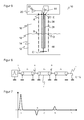
- FIG. 1 schematically illustrates a closed-loop TDR sensor 10 of the prior art mounted as a fill level sensor in a tank or container 12 with a medium or liquid 14.
- like reference numerals designate the same or mutatis mutandis corresponding elements, for example, the reference numeral 10 is also used below for sensors according to the invention, which also the basic structure of the sensor according to Figures 1 and 2 demonstrate.
- the liquid 14 forms an interface 18 with respect to the air 16.
- the sensor 10 is designed to determine the distance of the interface 18 and to derive from its known mounting position the level and if necessary based on the geometry of the container 12 and the amount of liquid 14 , Although the design of the sensor 10 as a level sensor is a very important field of application, the sensor 10 are used in principle in other areas where an interface is to be located. In particular, other boundary surfaces 18 are to be considered, for example between different liquids or to and between bulk material or granules.
- the sensor 10 has a sensor head 20 with a controller 22, which is preferably accommodated on a common board. Alternatively, several circuit boards or flexprint carriers connected via plugs are conceivable. To the controller 22, a coaxial probe 24 is connected, which has an outer conductor 26 and an inner conductor 28.
- the provided in the sensor head 20 controller 22 and its board is in FIG. 2 shown in a block diagram.
- the actual controller is a microprocessor 36, which may also be an FPGA, ASIC or a similar digital logic device.
- a time base circuit (not shown here) for controlling a microwave transmitter 38 and a microwave receiver 40 is provided.
- the transmitting and receiving unit 38, 40 is controlled by the time base circuit with two slightly different frequencies in order to achieve a time-extended recording of the receiving pulse profiles by the method of subsampling a plurality of receiving pulses. This time dilation is required because devices that could digitize the extremely short pulses with sufficient triggers either do not exist or are much too costly. Basically, of course, a direct sampling without timebase circuit is conceivable.
- a pulse is transmitted to the inner conductor 28 via the microwave transmitter 38, and the transit time of the reflex pulse generated at the interface 18 and received in the microwave receiver 40 is measured by the distance of the interface 18 and thus the level in FIG to determine the container 12.
- the conductors here the outer conductor 26, slots or other suitable openings to allow a liquid or measuring medium exchange, as far as this exchange is desired.
- this exchange it is often spoken only of air-filled, so this is usually meant this exchange with the environment.
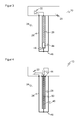
- FIG. 3 shows a first embodiment of a sensor according to the invention 10.
- the control elements in the sensor head 20 are shown here only in a rudimentary manner as the controller 22 in the form of a pulse generator.
- the remaining elements of the controller 22 are analogous to the description FIG. 2 to choose.
- a terminating resistor is arranged in the inner conductor 28 of the coaxial probe 24 in the inner conductor 28 of the coaxial probe 24.
- the terminating impedance is tuned to the characteristic impedance.
- a respective matching to the medium 14 terminating impedance can be selected, or you can choose as a compromise terminating impedance, which does not fit exactly, but is reasonably suitable for a wide range of media.
- the artifact pulse at the end of the probe 24 is then not prevented, but at least largely suppressed.
- One side of the resistor 44 is in direct contact with the inner conductor 28.
- the other side is connected to the outer conductor 26, for example, via a metallic wire 46 or other conductive connection.
- the wire 46 may consist of the same material as the outer conductor 26 of the probe 24.
- the passage of the wire 46 to the resistor 44 in the region of the inner conductor is insulated and forms an at least infinitesimal piece of a return conductor for the shaft.
- the end of the outer conductor 26 is provided with an electrically conductive bottom plate 48 and forms the second connection point for the terminating resistor 44. In this arrangement, only a minimal number of different materials in contact with the medium 14. At the same time are very low levels down to Top of the end plate 48 measurable. Due to their small thickness, a level measurement is thus possible up to the immediate vicinity of the bottom of the container 12.
- the outer conductor 26 and the bottom plate 48 are additionally provided with slots or openings through which the medium 14 can flow in and out.
- the inner coaxial line is filled with a material 50, for example with Teflon or a other material, preferably with a low relative dielectric constant. Consequently, liquid can not rise in it and no openings are provided in the inner conductor 26 for the liquid exchange.
- the impedance of the inner coaxial line and the resistor 44 are preferably matched to one another, in particular approximately equal to one another.
- FIG. 4 also describe that the terminating resistor 44 mounted in the inner conductor 28 in FIG. 3 is replaced by a semi-rigid coaxial cable to place the termination at a more convenient location inside the device.
- a semi-rigid coaxial cable with a characteristic impedance of, for example, 50 ohms are widespread and therefore relatively inexpensive to obtain.
- the characteristic impedance of the inner coaxial line always remains constant regardless of the level due to the permanently installed dielectric.
- the probe 24 always optimally and predictably completed with their characteristic impedance and an artifact pulse disturbing the measurement can be avoided.
- the following pulses are available for the evaluation: the first reflex pulse from position B during the transition from air to medium 14, the second reflected pulse from reversed sign from position D at transition medium 14 to air and the continuous pulse from position E. disturbing artifact pulse at position C, however, there are according to the invention with a correspondingly optimized configuration of the probe 24 is not, or it is at least largely suppressed in the case of remaining mismatches in the lower region of the probe 24.
- the transit time from the transmitter 38 at position A to the terminating resistor 44 at position E can also be used. Because of the delay in the range between B and D through the medium 14 run time is delayed by a value which is proportional to the level depending on the relative dielectric constant of the medium 14. With medium 14 within the probe 24, the throughput time is therefore always greater than when empty probe 24 or empty container 12 and approaches with increasing empty container 12 to the passage time at empty probe 24 at.
- the cycle time with empty probe 24 can serve as a reference or reference size. This value is determined mechanically and either known in advance or readily determinable by a calibration measurement when the container 12 is empty or without container 12.
- a first measured value for the fill level is provided by the known evaluation of the transit time of the first reflex pulse.
- the second reflex pulse is as above to FIG. 8 described one of artifacts undisturbed advanced evaluation possible.
- the fill level can also be taken from the transit time difference between the first reflex pulse and the second reflex pulse.
- the cycle time also provides a measured value for the fill level. In all these methods, the transmission pulse can make the reference.
- the pulse shape can therefore be used in addition to the pulse position for the measurement. This is a bit more complex and usually requires knowledge of the output pulse shapes. This in turn can be determined quite easily with the help of the through signal.
- the transit time measurement in addition to the extremum of the pulse, can refer to any other characteristic which can be mathematically extracted.
- FIGS. 5 to 8 described extensions, methods and advantages can be realized with other forms of the probe 24.
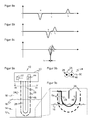
- FIG. 9a an embodiment with a U-shaped coaxial line.
- the inner conductor 28 is U-shaped in the return conductor 46, while both are surrounded by the likewise U-shaped outer conductor 26.
- FIG. 9b shows the probe 24 again in cross section. In this case, the repeatedly addressed openings 50 can be seen for exchange with the medium 14.
- FIG. 10a shows a further embodiment of the invention with a square configuration
- FIG. 10b represents the associated square conductor in cross section.
- This form of the probe 24 also has manufacturing advantages. The corners can be compensated for high-frequency technology, so as not to generate impulse reflexes. In the lower connection region of the probe 24 according to FIG. 10 already results due to the physical length of the horizontal sections improved separation of the pulse reflexes. It is possible to increase this effect even further by introducing one or more spacers with a relatively high dielectric constant, at least in partial regions of this connection region, in order to further delay the second pulse reflex and thereby separate it. The additional transit time difference can be taken into account by calibration or teaching in the measurements.
- the open design allows a simple and effective cleaning of the probe 24.
- spacers so-called spacers must be provided at regular intervals to ensure the spacing.
- spacers are problematic because the gaps and corners can not be cleaned to the required extent.
- the small parts could be lost and contaminate the medium 14. Therefore, in alternative embodiments, the probe 24, of which in FIG. 14b two variants are shown in cross-section, inner conductor 28 and return conductor 46 via a guided along the probe 24 support plastic 58 connected to the reference conductor 26 throughout. A rounded profile of these carrier plastics 58 simplifies the cleaning of the probe 24.
- the resulting round cross-sectional shape of the probe 24 is particularly advantageous.
- this can be coated with a shrink tube made of Teflon or a similar material. This eliminates any remaining impurities and unevenness in production engineering, resulting in a uniform and easy-to-clean surface, with which the probe 24 can be ideally used in the food industry.
- FIG. 16a the embodiment according to FIG. 15 again shown simplified and a further embodiment according to FIG. 16b compared.
- the air-filled recess grooves 60 according to FIG. 16a could lead to bulges or even fractures of the carrier 60 and thus prevent the use of the sensor 10 in some applications for larger external pressures, so pressure differences between the measurement environment and the resulting by the recess grooves 60 air chambers in the probe 24.
- the recess grooves 60 are filled, for example, with a plastic low relative dielectric constant.
- Inner conductor 28 and return conductor 46 can be applied directly to the plastic for easy production, for example as a Flexprint on Teflon.
- This arrangement is somewhat less sensitive because the plastic brings the characteristic impedance closer to the characteristic impedance in the surrounding medium 14 and therefore the jump at the interface 18 is slightly lower.
- the thickness of the intermediate wall 68 of the reference conductor between the recess grooves 60 of the reference conductor 26 can be varied.
- the conductors are connected via a central common (star) point, namely from the first conductor 28a with a characteristic impedance Z_1S, from the second conductor 28b with a characteristic impedance Z_2S and from the reference conductor 26 with a characteristic impedance Z_S0.
- an arbitrary deviating complex impedance can be selected independently for each of the specified characteristic impedances in order to achieve advantageous behavior in the currently selected evaluation method to reach.
- Z ⁇ 12 could, however, at the same time be designed as a pure inductance in order to achieve a propagation delay for the measurement signal and thus virtual extension of the probe 24 beyond its end.
- FIG. 20 an embodiment is shown, in addition, a DC decoupling to the reference conductor 26 is provided out.
- This can be analogously not only as shown with the triangle arrangement according to FIG. 18 , but also with the star arrangement according to FIG. 19 realize.
- the additional capacitor C causes a high-pass behavior.
- This galvanic isolation prevents the flow of a DC current through the individual conductors 28a, 28b to the reference conductor 26.
- the probe 24 can be galvanically separated from the transmitter or the reference conductor 26. This requirement often results from the selected device protection class.
- the power loss in the driver circuits can be minimized.
- a corresponding electrical isolation can also be made on the feed side at a suitable location.
- serial isolating capacitors are just as conceivable as the use of a transformer (Balun).
- each of the individual termination elements can consequently be realized as a purely real, purely imaginary or any complex termination impedance with corresponding behavior over the frequency.
- the termination impedance may consist of both single and a plurality of lumped devices such as resistors or distributed devices such as printed area resistors, printed transform or delay lines, and the like.
- Other examples include short circuit, open circuit, capacitive element, inductive element or real resistance.
- such elements have the required property targeted, so to a greater extent than the intrinsic and unavoidable conduction properties, but already a line extension can satisfy to increase such intrinsic properties.
- the input and / or output impedances of active circuits connected to the line system may take on the role of termination 46 and be designed to meet the desired design requirements.
- a defined reference surface or a reference conductor 26 offers some advantages. On the one hand, it can be used as a shield between the respectively executed as a double line conductor 28 and return conductor 46 to suppress unwanted couplings between the cable pairs. Furthermore, the common-mode and push-pull impedances of the lines are significantly less affected by external structures, thus the function of the probe 24 so much more independent of the geometry or the material of the container 12 or the installation of the sensor 10. As just explained, are in the optimization of such Arrangements, the common mode and push-pull impedances quite independently dimensioned.
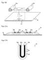
- FIG. 21 shows a further embodiment of the probe 24 as a flat probe for mounting on a wall of the container 12, wherein FIG. 21a a sectional view and FIG. 21b is a plan view looking towards the wall of the container 12.
- the reference conductor 26 is formed flat and has recesses 60 for the conductors 28a, 28b and return conductors 46a, 46b. These recesses 60 may be air or teflon filled and have shapes other than those illustrated, which encapsulate the conductors 28a, 28b and return conductors 46a, 46b differently.
- the probe 24 may be provided with a protective layer in advance or subsequently, whether by a foil, a coating or the coating with a protective material, which covers the probe 24 to the wall of the container 12 out. This prevents the adhesion of dirt, and the cleaning of the probe 24 takes place virtually indiscriminately to a container 12 without probe 24.
- a protective material are the materials mentioned several times such as Teflon, but also protective colors, protective pastes or gels including silicone.
- the protective material should be sufficiently hard, temperature resistant and resistant to media to provide a reliable, easy to use To create a cleansing and long-lasting probe 24 with a surface that is as homogeneous as possible and free of burrs and edges.
- the flat arrangement is particularly useful in hygienic applications in which the probe 24 should be easily cleanable by a spray.
- the problem is that results in a freely mounted probe 24 through the spray shadow on the probe back a worse cleaning effect.
- a surface mounted on the wall probe 24 avoids such Abschattungsprobleme.
- this probe 24 obstructs significantly less when filling or cleaning the container 12 and is therefore in turn protected against damage.
- the metallic or non-metallic container 12 integrally with the probe 24 from the outset.
- the reference conductor 26 is made of a highly electrically conductive, simultaneously flexible and media-resistant material, similar to soft pads for the direct connection of cables to a circuit board.
- FIG. 22 shows cross-sectional views of various embodiments of a differentially designed probe.
- Conceivable are round, square or elongated signal lines. Numerous other variants of the resulting Lecher line over a reference surface are similar to those in FIG. 11 shown possible for coaxial embodiments. Due to the cross-sectional representation, the lower connection regions between respective individual inner conductors 28a, 28b and associated individual return conductors 46a, 46b are not recognizable. These connection areas can be configured similarly to the above Figures 9 and 10 described so that, for example, creates a double round or square U-shape.
- the reference conductor 26 formed as a reference surface contributes significantly to the functionality of the probe 24 and acts as a screen which decouples the incoming from the returning signal path.
- Completely open designs like in the Figures 22a-22d are suitable for media 14 with a particularly low relative dielectric constant ⁇ r .
- mechanical stability requirements of the structure may necessitate positioning the individual conductors 28, 46 relative to the reference surface 26.
- Similar to the embodiment according to FIG. 14b can be used for continuous plastic carrier with the lowest possible dielectric constant ⁇ r , for example Teflon. It is advantageous to provide in each case a groove 70 between the plastic carriers of the individual conductors in order to use as little material as possible and thus to impair the field as little as possible with respect to vacuum. It is also conceivable to dispense with these grooves 70 or to train them differently.
- FIG. 23 shows a further embodiment of the invention, in which the probe 24 is designed to be flexible. This is particularly advantageous for large containers 12 and longer probes 24, approximately up to the range of 10 meters in length and more. Then rigid probes 24 are unwieldy and rope probes are preferred.
- FIG. 23a shows in each case two inner conductors 28a, 28b designed as round conductors and return conductors 46a, 46b, which are surrounded by an insulating jacket 72.
- the centered reference conductor 26 has an elongated cross-section and is surrounded by an insulating material 74 to space inner conductor 28 and return conductor 46.
- At the lower end of the probe 24 in each case one core of the inner conductor 28a, 28b is electrically connected to the associated core of the return conductor 46a, 46b.
- the probe 24 as a whole is enveloped by a suitable shrink tube 76.
- the insulating material 74 is further extended and simultaneously acts as a jacket 72. This results in a completely overmolded multi-wire line, which can optionally be surrounded by an additional heat-shrinkable tube 76.
Landscapes
- Physics & Mathematics (AREA)
- Electromagnetism (AREA)
- Thermal Sciences (AREA)
- Fluid Mechanics (AREA)
- General Physics & Mathematics (AREA)
- Measurement Of Levels Of Liquids Or Fluent Solid Materials (AREA)
Priority Applications (1)
| Application Number | Priority Date | Filing Date | Title |
|---|---|---|---|
| EP20080106008 EP2154496B1 (fr) | 2008-08-15 | 2008-12-17 | Capteur et procédé de mesure |
Applications Claiming Priority (2)
| Application Number | Priority Date | Filing Date | Title |
|---|---|---|---|
| EP20080105050 EP2154495B1 (fr) | 2008-08-15 | 2008-08-15 | Capteur TDR et procédé de mesure |
| EP20080106008 EP2154496B1 (fr) | 2008-08-15 | 2008-12-17 | Capteur et procédé de mesure |
Publications (2)
| Publication Number | Publication Date |
|---|---|
| EP2154496A1 true EP2154496A1 (fr) | 2010-02-17 |
| EP2154496B1 EP2154496B1 (fr) | 2014-09-17 |
Family
ID=39952347
Family Applications (2)
| Application Number | Title | Priority Date | Filing Date |
|---|---|---|---|
| EP20080105050 Not-in-force EP2154495B1 (fr) | 2008-08-15 | 2008-08-15 | Capteur TDR et procédé de mesure |
| EP20080106008 Not-in-force EP2154496B1 (fr) | 2008-08-15 | 2008-12-17 | Capteur et procédé de mesure |
Family Applications Before (1)
| Application Number | Title | Priority Date | Filing Date |
|---|---|---|---|
| EP20080105050 Not-in-force EP2154495B1 (fr) | 2008-08-15 | 2008-08-15 | Capteur TDR et procédé de mesure |
Country Status (1)
| Country | Link |
|---|---|
| EP (2) | EP2154495B1 (fr) |
Cited By (8)
| Publication number | Priority date | Publication date | Assignee | Title |
|---|---|---|---|---|
| DE102013101872A1 (de) * | 2013-02-26 | 2014-08-28 | boden & grundwasser GmbH Dr. Rainer Klein | Messverfahren |
| DE102013207604A1 (de) * | 2013-04-25 | 2014-11-13 | Krohne S.A. | Füllstandmessgerät |
| DE102014107393A1 (de) | 2014-05-26 | 2015-11-26 | Krohne S. A. S. | Abschlusselement für Füllstandmessgerät und Füllstandmessgerät |
| DE102016103430A1 (de) * | 2016-02-26 | 2017-08-31 | Finetek Co., Ltd. | Zeitbereichs-Reflektometrie-Wellenleiter |
| WO2019110103A1 (fr) * | 2017-12-07 | 2019-06-13 | Vega Grieshaber Kg | Détecteur de niveau et procédé pour le faire fonctionner |
| CN110446922A (zh) * | 2017-04-10 | 2019-11-12 | 普乐福尼克迪特布什有限责任公司 | 差分探头、探测装置和制造方法 |
| CN114217645A (zh) * | 2022-02-22 | 2022-03-22 | 深圳海润游艇码头工程有限公司 | 一种游艇码头智能水箱监测系统和方法 |
| WO2024256073A1 (fr) * | 2023-06-12 | 2024-12-19 | Vega Grieshaber Kg | Dispositif radar de niveau de remplissage et réservoir de gaz liquide |
Families Citing this family (10)
| Publication number | Priority date | Publication date | Assignee | Title |
|---|---|---|---|---|
| DE102012101725A1 (de) | 2012-03-01 | 2013-09-05 | Sick Ag | Verfahren zur Füllstandsmessung |
| GB201214579D0 (en) | 2012-08-15 | 2012-09-26 | Airbus Operations Ltd | Flanged cap for forming sealed cavity around fastener |
| EP2711673B1 (fr) * | 2012-09-25 | 2017-03-15 | VEGA Grieshaber KG | Sonde coaxiale avec résistance terminale et capeur de niveau de fluide à réflectométrie de domaine temporel |
| US9360361B2 (en) | 2012-09-27 | 2016-06-07 | Magnetrol International, Inc. | System and method for emulsion measurement and profiling |
| GB201220658D0 (en) | 2012-11-16 | 2013-01-02 | Airbus Operations Ltd | Time domain reflectometry fuel gauge |
| DE102016213324B3 (de) * | 2016-07-21 | 2017-08-31 | Ifm Electronic Gmbh | Füllstandsmessgerät nach dem Zeitbereichsreflektometrie-Prinzip sowie Verfahren zum Betreiben eines solchen Füllstandsmessgeräts |
| US10184820B2 (en) * | 2016-09-30 | 2019-01-22 | Rosemount Tank Radar Ab | Guided wave radar level gauge system for interface measurement |
| DE102019102812A1 (de) * | 2019-02-05 | 2020-08-06 | Sick Ag | Sensor zum Bestimmen einer Prozessgröße |
| DE102023124270A1 (de) * | 2023-09-08 | 2025-03-13 | Rheinmetall Air Defence Ag | Verfahren und gussformanordnung mit einer sensorvorrichtung zur detektion der präsenz von einer metallschmelze |
| EP4741778A1 (fr) * | 2024-11-11 | 2026-05-13 | Sick Ag | Dispositif de mesure de niveau |
Citations (11)
| Publication number | Priority date | Publication date | Assignee | Title |
|---|---|---|---|---|
| US4135397A (en) * | 1977-06-03 | 1979-01-23 | Krake Guss L | Level measuring system |
| WO1998024013A2 (fr) * | 1996-10-07 | 1998-06-04 | Berwind Corporation | Detecteur du niveau de l'interface de matieres |
| EP1069649A1 (fr) * | 1999-07-15 | 2001-01-17 | Endress + Hauser Gmbh + Co. | Guide d'ondes d'un détecteur de contenu opérant à micro-ondes |
| DE19958584C1 (de) | 1999-11-08 | 2001-02-01 | Krohne Sa | Füllstandmessgerät |
| EP1186869A2 (fr) * | 2000-09-06 | 2002-03-13 | VEGA Grieshaber KG | Dispositif de mesure du niveau d' un fluide |
| DE10044888A1 (de) | 2000-09-12 | 2002-04-04 | Grieshaber Vega Kg | Vorrichtung und Verfahren zur Ermittlung der Positionen der Grenzflächen unterschiedlicher Medien |
| DE10101714A1 (de) | 2000-11-13 | 2002-05-23 | Krohne Sa | Füllstandsmeßgerät |
| WO2002063249A2 (fr) * | 2001-02-08 | 2002-08-15 | Venture Measurement Company | Procede et systeme de detection du niveau de la matiere |
| EP0799407B1 (fr) | 1994-12-19 | 2003-05-21 | The Regents Of The University Of California | Capteur electronique polyvalent pour determiner le niveau d'un materiau |
| US20040046571A1 (en) * | 2002-09-09 | 2004-03-11 | Champion James Robert | Characterizing substances with multistatic probes |
| US20070090992A1 (en) | 2005-10-21 | 2007-04-26 | Olov Edvardsson | Radar level gauge system and transmission line probe for use in such a system |
Family Cites Families (4)
| Publication number | Priority date | Publication date | Assignee | Title |
|---|---|---|---|---|
| US5656774A (en) | 1996-06-04 | 1997-08-12 | Teleflex Incorporated | Apparatus and method for sensing fluid level |
| GB0004306D0 (en) | 2000-02-23 | 2000-04-12 | Cambridge Consultants | Time domain reflectometry |
| DE10045235A1 (de) | 2000-09-13 | 2002-03-28 | Endress Hauser Gmbh Co | Füllstandsmeßgerät |
| DE102004035757B3 (de) | 2004-07-23 | 2006-05-04 | imko Intelligente Micromodule Köhler GmbH | Anordnung zur Bestimmung der Höhe eines Flüssigkeitsstandes |
-
2008
- 2008-08-15 EP EP20080105050 patent/EP2154495B1/fr not_active Not-in-force
- 2008-12-17 EP EP20080106008 patent/EP2154496B1/fr not_active Not-in-force
Patent Citations (12)
| Publication number | Priority date | Publication date | Assignee | Title |
|---|---|---|---|---|
| US4135397A (en) * | 1977-06-03 | 1979-01-23 | Krake Guss L | Level measuring system |
| EP0799407B1 (fr) | 1994-12-19 | 2003-05-21 | The Regents Of The University Of California | Capteur electronique polyvalent pour determiner le niveau d'un materiau |
| WO1998024013A2 (fr) * | 1996-10-07 | 1998-06-04 | Berwind Corporation | Detecteur du niveau de l'interface de matieres |
| EP1069649A1 (fr) * | 1999-07-15 | 2001-01-17 | Endress + Hauser Gmbh + Co. | Guide d'ondes d'un détecteur de contenu opérant à micro-ondes |
| DE19958584C1 (de) | 1999-11-08 | 2001-02-01 | Krohne Sa | Füllstandmessgerät |
| EP1186869A2 (fr) * | 2000-09-06 | 2002-03-13 | VEGA Grieshaber KG | Dispositif de mesure du niveau d' un fluide |
| DE10043838A1 (de) | 2000-09-06 | 2002-04-04 | Grieshaber Vega Kg | Füllstandsmeßvorrichtung |
| DE10044888A1 (de) | 2000-09-12 | 2002-04-04 | Grieshaber Vega Kg | Vorrichtung und Verfahren zur Ermittlung der Positionen der Grenzflächen unterschiedlicher Medien |
| DE10101714A1 (de) | 2000-11-13 | 2002-05-23 | Krohne Sa | Füllstandsmeßgerät |
| WO2002063249A2 (fr) * | 2001-02-08 | 2002-08-15 | Venture Measurement Company | Procede et systeme de detection du niveau de la matiere |
| US20040046571A1 (en) * | 2002-09-09 | 2004-03-11 | Champion James Robert | Characterizing substances with multistatic probes |
| US20070090992A1 (en) | 2005-10-21 | 2007-04-26 | Olov Edvardsson | Radar level gauge system and transmission line probe for use in such a system |
Cited By (15)
| Publication number | Priority date | Publication date | Assignee | Title |
|---|---|---|---|---|
| DE102013101872A1 (de) * | 2013-02-26 | 2014-08-28 | boden & grundwasser GmbH Dr. Rainer Klein | Messverfahren |
| DE102013207604A1 (de) * | 2013-04-25 | 2014-11-13 | Krohne S.A. | Füllstandmessgerät |
| DE102013207604B4 (de) | 2013-04-25 | 2023-04-06 | Krohne S.A. | Füllstandmessgerät |
| DE102014107393B4 (de) | 2014-05-26 | 2020-04-23 | Krohne S. A. S. | Abschlusselement für Füllstandmessgerät und Füllstandmessgerät |
| DE102014107393A1 (de) | 2014-05-26 | 2015-11-26 | Krohne S. A. S. | Abschlusselement für Füllstandmessgerät und Füllstandmessgerät |
| EP2950059A1 (fr) | 2014-05-26 | 2015-12-02 | Krohne S.A.S. | Élément de fermeture pour appareil de mesure du niveau de remplissage et appareil de mesure du niveau de remplissage |
| US9698456B2 (en) | 2014-05-26 | 2017-07-04 | Krohne S.A.S. | Termination element for fill level measuring device and fill level measuring device |
| DE102016103430B4 (de) | 2016-02-26 | 2021-08-19 | Finetek Co., Ltd. | Zeitbereichs-Reflektometrie-Wellenleiterstruktur |
| DE102016103430A1 (de) * | 2016-02-26 | 2017-08-31 | Finetek Co., Ltd. | Zeitbereichs-Reflektometrie-Wellenleiter |
| CN110446922A (zh) * | 2017-04-10 | 2019-11-12 | 普乐福尼克迪特布什有限责任公司 | 差分探头、探测装置和制造方法 |
| CN110446922B (zh) * | 2017-04-10 | 2024-04-02 | 普乐福尼克迪特布什有限责任公司 | 差分探头、探测装置和制造方法 |
| WO2019110103A1 (fr) * | 2017-12-07 | 2019-06-13 | Vega Grieshaber Kg | Détecteur de niveau et procédé pour le faire fonctionner |
| CN114217645A (zh) * | 2022-02-22 | 2022-03-22 | 深圳海润游艇码头工程有限公司 | 一种游艇码头智能水箱监测系统和方法 |
| CN114217645B (zh) * | 2022-02-22 | 2022-05-06 | 深圳海润游艇码头工程有限公司 | 一种游艇码头智能水箱监测系统和方法 |
| WO2024256073A1 (fr) * | 2023-06-12 | 2024-12-19 | Vega Grieshaber Kg | Dispositif radar de niveau de remplissage et réservoir de gaz liquide |
Also Published As
| Publication number | Publication date |
|---|---|
| EP2154496B1 (fr) | 2014-09-17 |
| EP2154495A1 (fr) | 2010-02-17 |
| EP2154495B1 (fr) | 2013-05-22 |
Similar Documents
| Publication | Publication Date | Title |
|---|---|---|
| EP2154496B1 (fr) | Capteur et procédé de mesure | |
| EP2010871B1 (fr) | Procédé pour déterminer et surveiller le niveau de remplissage d'un fluide dans un récipient | |
| EP2652462B1 (fr) | Dispositif de mesure, dispositif de commande et appareil de mesure pour la mesure d'un niveau | |
| DE102010038732B4 (de) | Vorrichtung und Verfahren zur Sicherung der Befestigung eines koaxial um eine Messsonde angeordneten Rohres einer Messsondeneinheit eines Füllstandsmessgerätes an einem Prozessanschlusselement | |
| DE102010063167A1 (de) | Mit Mikrowellen arbeitendes Messgerät | |
| DE202008018156U1 (de) | Sensor nach dem TDR-Prinzip mit einer koaxialen Sonde | |
| EP2365302B1 (fr) | Mesure de la distance par rapport à, au moins, une première surface limite | |
| EP1972905B1 (fr) | Dispositif de mesure du niveau de remplissage | |
| EP2340420B1 (fr) | Appareil de mesure du niveau de remplissage | |
| EP2260274A1 (fr) | Capteur de niveau et élément de détection pour un capteur de niveau | |
| AT517604B1 (de) | Messfühler | |
| WO2007028775A1 (fr) | Dispositif pour determiner et surveiller le niveau d'un fluide dans un contenant | |
| EP2652465B1 (fr) | Détermination de propriétés de fluide lors de la mesure d'un niveau de remplissage | |
| DE19510484C2 (de) | Füllstandsmesser | |
| DE102020134061A1 (de) | Hochfrequenz-basiertes Feldgerät | |
| EP1069649B1 (fr) | Guide d'ondes d'un détecteur de contenu opérant à micro-ondes | |
| EP3447456A1 (fr) | Appareil de mesure de niveau de remplissage tdr et procédé de fonctionnement d'un appareil de mesure de niveau de remplissage tdr | |
| EP1774616B1 (fr) | Dispositif de transmission de signaux haute frequence à large bande | |
| EP3473988B1 (fr) | Dispositif de mesure d'un niveau de remplissage doté de guides d'ondes d'émission et de réception tubulaires et flexibles | |
| EP1274973A2 (fr) | Dispositif de determination du niveau de remplissage d'un recipient avec un agent de remplissage | |
| WO2025218985A1 (fr) | Dispositif de mesure de niveau de remplissage | |
| DE202013101738U1 (de) | Füllstandssensor zur Bestimmung eines Füllstands nach dem TDR-Prinzip | |
| EP1186869A2 (fr) | Dispositif de mesure du niveau d' un fluide | |
| EP3159662B1 (fr) | Sonde à corde, détecteur de niveau et procédé de fabrication d'une sonde à corde | |
| WO2012079643A1 (fr) | Dispositif pour la mesure d'une émulsion comportant un tube vertical |
Legal Events
| Date | Code | Title | Description |
|---|---|---|---|
| PUAI | Public reference made under article 153(3) epc to a published international application that has entered the european phase |
Free format text: ORIGINAL CODE: 0009012 |
|
| AK | Designated contracting states |
Kind code of ref document: A1 Designated state(s): AT BE BG CH CY CZ DE DK EE ES FI FR GB GR HR HU IE IS IT LI LT LU LV MC MT NL NO PL PT RO SE SI SK TR |
|
| AX | Request for extension of the european patent |
Extension state: AL BA MK RS |
|
| 17P | Request for examination filed |
Effective date: 20100628 |
|
| AKX | Designation fees paid |
Designated state(s): AT BE BG CH CY CZ DE DK EE ES FI FR GB GR HR HU IE IS IT LI LT LU LV MC MT NL NO PL PT RO SE SI SK TR |
|
| 17Q | First examination report despatched |
Effective date: 20130207 |
|
| GRAP | Despatch of communication of intention to grant a patent |
Free format text: ORIGINAL CODE: EPIDOSNIGR1 |
|
| INTG | Intention to grant announced |
Effective date: 20140611 |
|
| GRAS | Grant fee paid |
Free format text: ORIGINAL CODE: EPIDOSNIGR3 |
|
| GRAA | (expected) grant |
Free format text: ORIGINAL CODE: 0009210 |
|
| AK | Designated contracting states |
Kind code of ref document: B1 Designated state(s): AT BE BG CH CY CZ DE DK EE ES FI FR GB GR HR HU IE IS IT LI LT LU LV MC MT NL NO PL PT RO SE SI SK TR |
|
| REG | Reference to a national code |
Ref country code: GB Ref legal event code: FG4D Free format text: NOT ENGLISH |
|
| REG | Reference to a national code |
Ref country code: CH Ref legal event code: EP |
|
| REG | Reference to a national code |
Ref country code: IE Ref legal event code: FG4D Free format text: LANGUAGE OF EP DOCUMENT: GERMAN |
|
| REG | Reference to a national code |
Ref country code: AT Ref legal event code: REF Ref document number: 687903 Country of ref document: AT Kind code of ref document: T Effective date: 20141015 |
|
| REG | Reference to a national code |
Ref country code: DE Ref legal event code: R096 Ref document number: 502008012218 Country of ref document: DE Effective date: 20141030 |
|
| PG25 | Lapsed in a contracting state [announced via postgrant information from national office to epo] |
Ref country code: NO Free format text: LAPSE BECAUSE OF FAILURE TO SUBMIT A TRANSLATION OF THE DESCRIPTION OR TO PAY THE FEE WITHIN THE PRESCRIBED TIME-LIMIT Effective date: 20141217 Ref country code: SE Free format text: LAPSE BECAUSE OF FAILURE TO SUBMIT A TRANSLATION OF THE DESCRIPTION OR TO PAY THE FEE WITHIN THE PRESCRIBED TIME-LIMIT Effective date: 20140917 Ref country code: FI Free format text: LAPSE BECAUSE OF FAILURE TO SUBMIT A TRANSLATION OF THE DESCRIPTION OR TO PAY THE FEE WITHIN THE PRESCRIBED TIME-LIMIT Effective date: 20140917 Ref country code: LT Free format text: LAPSE BECAUSE OF FAILURE TO SUBMIT A TRANSLATION OF THE DESCRIPTION OR TO PAY THE FEE WITHIN THE PRESCRIBED TIME-LIMIT Effective date: 20140917 Ref country code: GR Free format text: LAPSE BECAUSE OF FAILURE TO SUBMIT A TRANSLATION OF THE DESCRIPTION OR TO PAY THE FEE WITHIN THE PRESCRIBED TIME-LIMIT Effective date: 20141218 |
|
| REG | Reference to a national code |
Ref country code: NL Ref legal event code: VDEP Effective date: 20140917 |
|
| REG | Reference to a national code |
Ref country code: LT Ref legal event code: MG4D |
|
| PG25 | Lapsed in a contracting state [announced via postgrant information from national office to epo] |
Ref country code: CY Free format text: LAPSE BECAUSE OF FAILURE TO SUBMIT A TRANSLATION OF THE DESCRIPTION OR TO PAY THE FEE WITHIN THE PRESCRIBED TIME-LIMIT Effective date: 20140917 Ref country code: LV Free format text: LAPSE BECAUSE OF FAILURE TO SUBMIT A TRANSLATION OF THE DESCRIPTION OR TO PAY THE FEE WITHIN THE PRESCRIBED TIME-LIMIT Effective date: 20140917 Ref country code: HR Free format text: LAPSE BECAUSE OF FAILURE TO SUBMIT A TRANSLATION OF THE DESCRIPTION OR TO PAY THE FEE WITHIN THE PRESCRIBED TIME-LIMIT Effective date: 20140917 |
|
| PG25 | Lapsed in a contracting state [announced via postgrant information from national office to epo] |
Ref country code: NL Free format text: LAPSE BECAUSE OF FAILURE TO SUBMIT A TRANSLATION OF THE DESCRIPTION OR TO PAY THE FEE WITHIN THE PRESCRIBED TIME-LIMIT Effective date: 20140917 |
|
| PG25 | Lapsed in a contracting state [announced via postgrant information from national office to epo] |
Ref country code: EE Free format text: LAPSE BECAUSE OF FAILURE TO SUBMIT A TRANSLATION OF THE DESCRIPTION OR TO PAY THE FEE WITHIN THE PRESCRIBED TIME-LIMIT Effective date: 20140917 Ref country code: RO Free format text: LAPSE BECAUSE OF FAILURE TO SUBMIT A TRANSLATION OF THE DESCRIPTION OR TO PAY THE FEE WITHIN THE PRESCRIBED TIME-LIMIT Effective date: 20140917 Ref country code: IS Free format text: LAPSE BECAUSE OF FAILURE TO SUBMIT A TRANSLATION OF THE DESCRIPTION OR TO PAY THE FEE WITHIN THE PRESCRIBED TIME-LIMIT Effective date: 20150117 Ref country code: CZ Free format text: LAPSE BECAUSE OF FAILURE TO SUBMIT A TRANSLATION OF THE DESCRIPTION OR TO PAY THE FEE WITHIN THE PRESCRIBED TIME-LIMIT Effective date: 20140917 Ref country code: SK Free format text: LAPSE BECAUSE OF FAILURE TO SUBMIT A TRANSLATION OF THE DESCRIPTION OR TO PAY THE FEE WITHIN THE PRESCRIBED TIME-LIMIT Effective date: 20140917 Ref country code: PT Free format text: LAPSE BECAUSE OF FAILURE TO SUBMIT A TRANSLATION OF THE DESCRIPTION OR TO PAY THE FEE WITHIN THE PRESCRIBED TIME-LIMIT Effective date: 20150119 Ref country code: ES Free format text: LAPSE BECAUSE OF FAILURE TO SUBMIT A TRANSLATION OF THE DESCRIPTION OR TO PAY THE FEE WITHIN THE PRESCRIBED TIME-LIMIT Effective date: 20140917 |
|
| PG25 | Lapsed in a contracting state [announced via postgrant information from national office to epo] |
Ref country code: PL Free format text: LAPSE BECAUSE OF FAILURE TO SUBMIT A TRANSLATION OF THE DESCRIPTION OR TO PAY THE FEE WITHIN THE PRESCRIBED TIME-LIMIT Effective date: 20140917 |
|
| REG | Reference to a national code |
Ref country code: DE Ref legal event code: R097 Ref document number: 502008012218 Country of ref document: DE |
|
| PG25 | Lapsed in a contracting state [announced via postgrant information from national office to epo] |
Ref country code: BE Free format text: LAPSE BECAUSE OF NON-PAYMENT OF DUE FEES Effective date: 20141231 |
|
| PLBE | No opposition filed within time limit |
Free format text: ORIGINAL CODE: 0009261 |
|
| STAA | Information on the status of an ep patent application or granted ep patent |
Free format text: STATUS: NO OPPOSITION FILED WITHIN TIME LIMIT |
|
| PG25 | Lapsed in a contracting state [announced via postgrant information from national office to epo] |
Ref country code: DK Free format text: LAPSE BECAUSE OF FAILURE TO SUBMIT A TRANSLATION OF THE DESCRIPTION OR TO PAY THE FEE WITHIN THE PRESCRIBED TIME-LIMIT Effective date: 20140917 Ref country code: LU Free format text: LAPSE BECAUSE OF FAILURE TO SUBMIT A TRANSLATION OF THE DESCRIPTION OR TO PAY THE FEE WITHIN THE PRESCRIBED TIME-LIMIT Effective date: 20141217 |
|
| 26N | No opposition filed |
Effective date: 20150618 |
|
| PG25 | Lapsed in a contracting state [announced via postgrant information from national office to epo] |
Ref country code: IT Free format text: LAPSE BECAUSE OF FAILURE TO SUBMIT A TRANSLATION OF THE DESCRIPTION OR TO PAY THE FEE WITHIN THE PRESCRIBED TIME-LIMIT Effective date: 20140917 |
|
| REG | Reference to a national code |
Ref country code: IE Ref legal event code: MM4A |
|
| PG25 | Lapsed in a contracting state [announced via postgrant information from national office to epo] |
Ref country code: IE Free format text: LAPSE BECAUSE OF NON-PAYMENT OF DUE FEES Effective date: 20141217 |
|
| PG25 | Lapsed in a contracting state [announced via postgrant information from national office to epo] |
Ref country code: SI Free format text: LAPSE BECAUSE OF FAILURE TO SUBMIT A TRANSLATION OF THE DESCRIPTION OR TO PAY THE FEE WITHIN THE PRESCRIBED TIME-LIMIT Effective date: 20140917 |
|
| REG | Reference to a national code |
Ref country code: FR Ref legal event code: PLFP Year of fee payment: 8 |
|
| REG | Reference to a national code |
Ref country code: AT Ref legal event code: MM01 Ref document number: 687903 Country of ref document: AT Kind code of ref document: T Effective date: 20141217 |
|
| PG25 | Lapsed in a contracting state [announced via postgrant information from national office to epo] |
Ref country code: MC Free format text: LAPSE BECAUSE OF FAILURE TO SUBMIT A TRANSLATION OF THE DESCRIPTION OR TO PAY THE FEE WITHIN THE PRESCRIBED TIME-LIMIT Effective date: 20140917 Ref country code: AT Free format text: LAPSE BECAUSE OF NON-PAYMENT OF DUE FEES Effective date: 20141217 Ref country code: BG Free format text: LAPSE BECAUSE OF FAILURE TO SUBMIT A TRANSLATION OF THE DESCRIPTION OR TO PAY THE FEE WITHIN THE PRESCRIBED TIME-LIMIT Effective date: 20140917 |
|
| PG25 | Lapsed in a contracting state [announced via postgrant information from national office to epo] |
Ref country code: TR Free format text: LAPSE BECAUSE OF FAILURE TO SUBMIT A TRANSLATION OF THE DESCRIPTION OR TO PAY THE FEE WITHIN THE PRESCRIBED TIME-LIMIT Effective date: 20140917 Ref country code: MT Free format text: LAPSE BECAUSE OF FAILURE TO SUBMIT A TRANSLATION OF THE DESCRIPTION OR TO PAY THE FEE WITHIN THE PRESCRIBED TIME-LIMIT Effective date: 20140917 Ref country code: HU Free format text: LAPSE BECAUSE OF FAILURE TO SUBMIT A TRANSLATION OF THE DESCRIPTION OR TO PAY THE FEE WITHIN THE PRESCRIBED TIME-LIMIT; INVALID AB INITIO Effective date: 20081217 |
|
| REG | Reference to a national code |
Ref country code: FR Ref legal event code: PLFP Year of fee payment: 9 |
|
| REG | Reference to a national code |
Ref country code: FR Ref legal event code: PLFP Year of fee payment: 10 |
|
| PGFP | Annual fee paid to national office [announced via postgrant information from national office to epo] |
Ref country code: CH Payment date: 20171221 Year of fee payment: 10 |
|
| PGFP | Annual fee paid to national office [announced via postgrant information from national office to epo] |
Ref country code: FR Payment date: 20181218 Year of fee payment: 11 Ref country code: GB Payment date: 20181219 Year of fee payment: 11 |
|
| REG | Reference to a national code |
Ref country code: CH Ref legal event code: PL |
|
| PG25 | Lapsed in a contracting state [announced via postgrant information from national office to epo] |
Ref country code: CH Free format text: LAPSE BECAUSE OF NON-PAYMENT OF DUE FEES Effective date: 20181231 Ref country code: LI Free format text: LAPSE BECAUSE OF NON-PAYMENT OF DUE FEES Effective date: 20181231 |
|
| PGFP | Annual fee paid to national office [announced via postgrant information from national office to epo] |
Ref country code: DE Payment date: 20191217 Year of fee payment: 12 |
|
| GBPC | Gb: european patent ceased through non-payment of renewal fee |
Effective date: 20191217 |
|
| PG25 | Lapsed in a contracting state [announced via postgrant information from national office to epo] |
Ref country code: GB Free format text: LAPSE BECAUSE OF NON-PAYMENT OF DUE FEES Effective date: 20191217 Ref country code: FR Free format text: LAPSE BECAUSE OF NON-PAYMENT OF DUE FEES Effective date: 20191231 |
|
| REG | Reference to a national code |
Ref country code: DE Ref legal event code: R119 Ref document number: 502008012218 Country of ref document: DE |
|
| PG25 | Lapsed in a contracting state [announced via postgrant information from national office to epo] |
Ref country code: DE Free format text: LAPSE BECAUSE OF NON-PAYMENT OF DUE FEES Effective date: 20210701 |