EP2155382B1 - Procédé de production d'un catalyseur sous enveloppe, catalyseur sous enveloppe et son utilisation - Google Patents
Procédé de production d'un catalyseur sous enveloppe, catalyseur sous enveloppe et son utilisation Download PDFInfo
- Publication number
- EP2155382B1 EP2155382B1 EP08758899.2A EP08758899A EP2155382B1 EP 2155382 B1 EP2155382 B1 EP 2155382B1 EP 08758899 A EP08758899 A EP 08758899A EP 2155382 B1 EP2155382 B1 EP 2155382B1
- Authority
- EP
- European Patent Office
- Prior art keywords
- catalyst
- shell
- catalyst support
- catalytically active
- active species
- Prior art date
- Legal status (The legal status is an assumption and is not a legal conclusion. Google has not performed a legal analysis and makes no representation as to the accuracy of the status listed.)
- Active
Links
Images


Classifications
-
- B—PERFORMING OPERATIONS; TRANSPORTING
- B01—PHYSICAL OR CHEMICAL PROCESSES OR APPARATUS IN GENERAL
- B01J—CHEMICAL OR PHYSICAL PROCESSES, e.g. CATALYSIS OR COLLOID CHEMISTRY; THEIR RELEVANT APPARATUS
- B01J23/00—Catalysts comprising metals or metal oxides or hydroxides, not provided for in group B01J21/00
- B01J23/38—Catalysts comprising metals or metal oxides or hydroxides, not provided for in group B01J21/00 of noble metals
- B01J23/54—Catalysts comprising metals or metal oxides or hydroxides, not provided for in group B01J21/00 of noble metals combined with metals, oxides or hydroxides provided for in groups B01J23/02 - B01J23/36
- B01J23/66—Silver or gold
-
- B—PERFORMING OPERATIONS; TRANSPORTING
- B01—PHYSICAL OR CHEMICAL PROCESSES OR APPARATUS IN GENERAL
- B01J—CHEMICAL OR PHYSICAL PROCESSES, e.g. CATALYSIS OR COLLOID CHEMISTRY; THEIR RELEVANT APPARATUS
- B01J2/00—Processes or devices for granulating materials, e.g. fertilisers in general; Rendering particulate materials free flowing in general, e.g. making them hydrophobic
- B01J2/16—Processes or devices for granulating materials, e.g. fertilisers in general; Rendering particulate materials free flowing in general, e.g. making them hydrophobic by suspending the powder material in a gas, e.g. in fluidised beds or as a falling curtain
-
- B—PERFORMING OPERATIONS; TRANSPORTING
- B01—PHYSICAL OR CHEMICAL PROCESSES OR APPARATUS IN GENERAL
- B01J—CHEMICAL OR PHYSICAL PROCESSES, e.g. CATALYSIS OR COLLOID CHEMISTRY; THEIR RELEVANT APPARATUS
- B01J23/00—Catalysts comprising metals or metal oxides or hydroxides, not provided for in group B01J21/00
- B01J23/70—Catalysts comprising metals or metal oxides or hydroxides, not provided for in group B01J21/00 of the iron group metals or copper
-
- B—PERFORMING OPERATIONS; TRANSPORTING
- B01—PHYSICAL OR CHEMICAL PROCESSES OR APPARATUS IN GENERAL
- B01J—CHEMICAL OR PHYSICAL PROCESSES, e.g. CATALYSIS OR COLLOID CHEMISTRY; THEIR RELEVANT APPARATUS
- B01J35/00—Catalysts, in general, characterised by their form or physical properties
- B01J35/30—Catalysts, in general, characterised by their form or physical properties characterised by their physical properties
- B01J35/396—Distribution of the active metal ingredient
- B01J35/397—Egg shell like
-
- B—PERFORMING OPERATIONS; TRANSPORTING
- B01—PHYSICAL OR CHEMICAL PROCESSES OR APPARATUS IN GENERAL
- B01J—CHEMICAL OR PHYSICAL PROCESSES, e.g. CATALYSIS OR COLLOID CHEMISTRY; THEIR RELEVANT APPARATUS
- B01J37/00—Processes, in general, for preparing catalysts; Processes, in general, for activation of catalysts
- B01J37/02—Impregnation, coating or precipitation
- B01J37/0215—Coating
- B01J37/0221—Coating of particles
-
- C—CHEMISTRY; METALLURGY
- C07—ORGANIC CHEMISTRY
- C07C—ACYCLIC OR CARBOCYCLIC COMPOUNDS
- C07C67/00—Preparation of carboxylic acid esters
- C07C67/04—Preparation of carboxylic acid esters by reacting carboxylic acids or symmetrical anhydrides onto unsaturated carbon-to-carbon bonds
- C07C67/05—Preparation of carboxylic acid esters by reacting carboxylic acids or symmetrical anhydrides onto unsaturated carbon-to-carbon bonds with oxidation
- C07C67/055—Preparation of carboxylic acid esters by reacting carboxylic acids or symmetrical anhydrides onto unsaturated carbon-to-carbon bonds with oxidation in the presence of platinum group metals or their compounds
Definitions
- the present invention relates to a process for producing a coated catalyst comprising a porous catalyst support molding having an outer shell in which at least one catalytically active species is contained.
- Shell catalysts and processes for their preparation are known in the art.
- the catalytically active species - often including the promoters - are contained only in a more or less wide outer region (shell) of a catalyst support molding, ie they do not completely penetrate the catalyst support molding (cf., for example EP 565 952 A1 .
- EP 634 209 A1 and EP 634 208 A1 With coated catalysts, a more selective reaction is possible in many cases than with catalysts in which the carrier is loaded ("impregnated") into the carrier core with the catalytically active species.
- Vinyl acetate monomer for example, is currently produced predominantly by coated catalysts in high selectivity.
- the majority of the currently used coated catalysts for the preparation of VAM are coated catalysts with a Pd / Au shell on a porous amorphous formed as a ball aluminosilicate on the basis of natural phyllosilicates, which are impregnated with potassium acetate as a promoter.
- the active metals Pd and Au are presumed not in the form of metal particles of the respective pure metal, but rather in the form of Pd / Au alloy particles of possibly different composition, although the presence of unalloyed particles can not be excluded.
- VAM shell catalysts are usually prepared by a so-called chemical route in which the catalyst support is reacted with solutions of corresponding metal compounds, for example, by immersing the support in the solutions or by incipient wetness method (pore filling method) in which the support has a pore volume corresponding thereto Solution volume is loaded, is soaked.
- chemical route in which the catalyst support is reacted with solutions of corresponding metal compounds, for example, by immersing the support in the solutions or by incipient wetness method (pore filling method) in which the support has a pore volume corresponding thereto Solution volume is loaded, is soaked.
- the WO 99/62632 A1 describes a catalyst for the production of vinyl acetate by reaction of ethylene, oxygen and acetic acid, comprising a porous support having deposited on the porous surfaces catalytically effective amounts of metallic palladium and gold.
- This catalyst was prepared by impregnating a porous support whose porous surfaces contain a catalytically effective amount of prereduced metallic palladium with a solution of potassium aurate, followed by reducing the potassium auricate to a catalytically effective amount of metallic gold.
- the Pd / Au shell of a VAM shell catalyst is produced, for example, by first impregnating the catalyst support molding in a first step with a Na 2 PdCl 4 solution and then in a second step the Pd component with NaOH solution on the catalyst support is fixed in the form of a Pd hydroxide compound. In a subsequent separate third step, the catalyst support is then impregnated with a NaAuCl 4 solution and then the Au component is likewise fixed by means of NaOH. For example, it is also possible first to impregnate the carrier with caustic and then to apply the precursor compounds to the carrier pretreated in this way.
- the Pd / Au shell produced usually has a thickness of about 100 to 500 ⁇ m, with the smaller the thickness of its shell, the higher the product selectivity of a shell catalyst is, in general.
- the catalyst support loaded with the noble metals is then loaded with potassium acetate, the loading with potassium acetate not only taking place in the outer shell loaded with precious metals, but rather completely impregnated with the promoter by the promoter.
- the active metals Pd and Au are applied starting from chloride compounds in the region of a shell of the support on the same by means of impregnation.
- this technique has reached its limits in terms of minimum shell thicknesses and maximum Au loading.
- the thinnest achievable shell thickness according to VAM catalysts produced is at best about 100 microns and it is not foreseeable that even thinner shells can be obtained by impregnation.
- the impregnated catalysts have inconsistent shell thicknesses and, over relatively large portions of their shell thickness, a very non-uniform concentration of catalytically active species, which can adversely affect product selectivity as well as catalyst activity.
- coated catalysts can be produced by means of the process according to the invention which have a largely uniform concentration of catalytically active species and a largely uniform shell thickness over large areas of their shell thickness.
- catalysts with very thin shells for example less than 100 ⁇ m, can be produced by means of the process according to the invention.
- shell catalysts produced by the process according to the invention are characterized in comparison to by catalysts produced by methods known in the art by increased activity.
- the catalyst support molding may be subjected to the method according to the invention frequently.
- the process of the invention may be carried out with mixed solutions containing the desired, distinct, catalytically active species or precursors thereof.
- the catalyst supports can be sprayed simultaneously with mutually different solutions of different catalytically active species or precursors thereof.
- Shelled catalysts can be prepared by means of the process according to the invention whose catalytically active species concentration is catalytically active over a range of 90% of the shell thickness, with the outer shell and inner shell boundary being each separated by 5% of the shell thickness Species varies from +/- 3 to a maximum of +/- 20%.
- the method according to the invention has the advantage that batches can be produced by means of this method with a large number of coated catalysts whose ratio of the standard deviation of their shell thickness to the mean value of the shell thickness is less than or equal to 20%. Such values are not achieved by the methods known in the art for the preparation of coated catalysts.
- the drying of the moldings sprayed with the solution takes place in the context of the method according to the invention preferably continuously by means of the process gas.
- a separate final drying step is carried out.
- the drying rate and thus the penetration depth (thickness of the shell) can be set individually
- the second case can be dried by any known to those skilled in drying method.
- Devices for carrying out the method according to the invention are, for example, in the documents WO 2006/027009 A1 . DE 102 48 116 B3 . EP 0 370 167 A1 . EP 0 436 787 B1 . DE 199 04 147 A1 . DE 20 2005 003 791 U1 whose contents are incorporated by referencing in the present invention.
- this describes the WO 2006/027009 A1 a device for treating particulate material, comprising a process chamber for receiving and treating the material having a bottom, which is composed of a plurality of superimposed, overlapping annular guide plates, between which annular slots are formed, via the process air with a essentially horizontal, radially outward movement component can be inserted.
- Subject of the WO 02/100527 A1 is a device for treating particulate material, comprising a process chamber for receiving and treating the material, wherein a bottom of the process chamber is constructed of overlapping guide plates, between which slots are formed over the Process air is introduced with a substantially horizontal component of movement in the process chamber, wherein the slots are arranged such that two mutually directed flows arise, which meet along a break-up zone and are deflected in a vertically upward flow.
- Fluid bed apparatuses which are particularly preferred for carrying out the process according to the invention are sold by Innojet Technologies under the names Innojet® Ventilus or Innojet® AirCoater. These devices comprise a cylindrical container with a fixed and immovably installed container bottom, in the middle of which a spray nozzle is mounted.
- the floor consists of circular lamellae, which are gradually mounted one above the other.
- the process air flows between the individual slats horizontally eccentrically with a circumferential flow component outward in the direction of the container wall into the container.
- so-called air sliding layers form, on which the catalyst carrier shaped bodies are initially transported outwards in the direction of the container wall.
- a vertically aligned process air flow is installed, which deflects the catalyst carriers upwards.
- the catalyst carriers move back on a tangential path toward the center of the floor, passing the nozzle's spray. After the mist has passed, the described movement process starts again.
- the process air guidance described here provides the basis for a largely homogeneous toroidal fluidized bed-like circulation movement of the catalyst support.
- a fluidized bed is produced in which the molded bodies rotate in an elliptical or toroidal manner.
- the transition of the particles of a bed to a state in which the particles are completely free to move referred to as a relaxation point (fluidized point) and the corresponding fluid velocity as loosening speed.
- the fluid velocity is up to 4 times the loosening speed, preferably up to three times the loosening speed and more preferably up to 2 times the loosening speed.
- the fluid velocity is up to 1.4 times the logarithm of the relaxation rate, preferably up to 1.3 times the logarithm of the loosening rate, and more preferably up to 1.2 times the decimal logarithm of the relaxation rate.
- catalyst support shaped body The terms “catalyst support shaped body”, “catalyst support”, “shaped body” and “support” are used synonymously in the context of the present invention.
- the catalyst support shaped bodies run in the fluidized bed elliptically or toroidally, preferably toroidally.
- elliptical circulation the catalyst support moldings in the fluidized bed move in a vertical plane on an elliptical path of varying major and minor axis sizes.
- toroidal recirculation the catalyst support moldings in the fluidized bed move in a vertical plane on an elliptical orbit of varying major and minor axis size and in a horizontal plane on a circular orbit of varying radius of radius.
- the process of the invention further comprises a step of converting the precursor into the corresponding catalytically active species.
- the conversion of the precursor can be carried out with the aid of any method known to those skilled in the art as suitable for the process according to the invention.
- the device comprises a process chamber with a bottom and a side wall wherein the process gas is introduced through the bottom of the process chamber, which is preferably constructed of a plurality of superimposed, overlapping annular guide plates, between which annular slots are formed, with a horizontal, radially outward movement component in the process chamber.
- circumferential flow component In order to impose the circumferential flow component on the process gas introduced into the process chamber, it can be provided according to a preferred embodiment of the method according to the invention that appropriately shaped and aligned process gas guide elements are arranged between the annular guide plates. Alternatively or additionally, it can be provided that the circumferential flow component is imposed on the process gas introduced into the process chamber by introducing additional process gas with an obliquely upward movement component into the process chamber through the bottom of the process chamber, preferably in the region of the side wall of the process chamber ,
- the spraying of the circulating in the fluidized bed catalyst support molded body is carried out with the solution by means of an annular gap nozzle which sprays a spray cloud, wherein the plane of symmetry of the spray plume is preferably parallel to the plane of the device floor. Due to the 360 ° circumference of the spray cloud, the centrally moving down moldings can be sprayed particularly evenly with the solution.
- the annular gap nozzle ie its mouth, is preferably completely embedded in the fluidized bed.
- the annular gap nozzle is arranged centrally in the bottom and the mouth of the annular gap nozzle is completely embedded in the fluidized bed. This ensures that the free path of the droplets of the spray cloud is relatively short until it encounters a molded body and relatively little time remains corresponding to the drops to coalesce into larger drops, which could counteract the formation of a largely uniform shell thickness.
- a gas support pad may be effected on the underside of the spray cloud.
- the bottom-side pad keeps the bottom surface largely free of sprayed solution, that is, almost all the sprayed solution is introduced into the fluidized bed of the moldings, so that hardly spray losses occur, which is particularly important in terms of expensive precious metals / compounds or enzymes for cost reasons ,
- the catalyst support is spherical. This ensures a uniform rotation of the support about its axis and, consequently, a uniform impregnation of the catalyst support with the solution of the catalytically active species.
- the carrier may be formed from all materials or material mixtures.
- the catalyst support comprises a silica, an alumina, an aluminosilicate, a zirconia, a titania, a niobium oxide or a natural layered silicate, preferably a calcined acid-treated bentonite.
- natural phyllosilicate for which the term “phyllosilicate” is used in the literature, is understood to mean untreated or treated silicate mineral originating from natural sources in which SiO 4 tetrahedra, which form the structural unit of all silicates, are present in Layers of the general formula [Si 2 O 5 ] 2- are cross-linked with each other. These tetrahedral layers alternate with so-called octahedral layers, in which a cation, especially Al and Mg, is octahedrally surrounded by OH or O. For example, a distinction is made between two-layer phyllosilicates and three-layer phyllosilicates.
- Phyllosilicates preferred in the context of the present invention are clay minerals, in particular kaolinite, beidellite, hectorite, saponite, nontronite, mica, vermiculite and smectites, with smectites and in particular montmorillonite being particularly preferred.
- sheet silicates can be found, for example, in " Textbook of inorganic chemistry ", Hollemann Wiberg, de Gruyter, 102nd edition, 2007 (ISBN 978-3-11-017770-1 ) or in " Römpp Lexikon Chemie “, 10th edition, Georg Thieme Verlag under the term “phyllosilicate”.
- Typical treatments to which a natural layered silicate is subjected prior to use as a carrier include, for example, treatment with acids and / or calcining.
- One in the context of the present Invention particularly preferred natural phyllosilicate is a bentonite.
- Bentonites are not natural layer silicates in the actual sense, but rather a mixture of predominantly clay minerals, in which phyllosilicates are contained. In the present case, therefore, in the case where the natural sheet silicate is a bentonite, it is to be understood that the natural sheet silicate is present in the catalyst support in the form or as part of a bentonite.
- a catalyst support based on natural sheet silicates, in particular on the basis of an acid-treated calcined bentonite can be produced, for example, by forming a mixture containing an acid-treated (uncalcined) bentonite as sheet silicate and water while compacting it into a shaped body by means of devices known to the person skilled in the art , such as extruders or tablet presses, molded and then the uncured molded body is calcined to form a stable molded body.
- the size of the specific surface of the catalyst support depends in particular on the quality of the (raw) bentonite used, the acid treatment process of the bentonite used, i. for example, the nature and relative to the bentonite amount and the concentration of the inorganic acid used, the acid treatment time and temperature, the compression pressure and the calcination time and temperature and the calcination atmosphere.
- Acid-treated bentonites can be obtained by treating bentonites with strong acids, such as sulfuric acid, phosphoric acid or hydrochloric acid.
- strong acids such as sulfuric acid, phosphoric acid or hydrochloric acid.
- bentonite which also applies in the context of the present invention is given in Rompp, Lexicon Chemistry, 10th ed., Georg Thieme Verlag , stated.
- Bentonites which are particularly preferred in the context of the present invention are natural aluminum-containing sheet silicates which contain montmorillonite (as smectite) as the main mineral. After the acid treatment, the bentonite is usually washed with water, dried and ground to a powder.
- the catalyst support has a surface area of 160 m 2 / g or less, preferably one of less than 140 m 2 / g, preferably less than 135 m 2 / g, more preferably one of less than 120 m 2 / g, more preferably one of less than 100 m 2 / g, even more preferably one of less than 80 m 2 / g and particularly preferably one of less than 65 m 2 / g.
- the term "surface area" of the catalyst support is understood to mean the BET surface area of the support, which is determined by adsorption of nitrogen in accordance with DIN 66132.
- the catalyst support has a surface area of 160 to 40 m 2 / g, preferably one of between 140 and 50 m 2 / g, preferably one of between 135 and 50 m 2 / g , more preferably one of between 120 and 50 m 2 / g, more preferably between 100 and 50 m 2 / g and most preferably between 100 and 60 m 2 / g.
- the catalyst supports When circulating the carrier in the context of the method according to the invention, the catalyst supports are mechanically stressed, which can lead to a certain abrasion and a certain damage of catalyst supports, in particular in the region of the resulting shell.
- the catalyst support has a hardness greater than or equal to 20 N, preferably greater than or equal to 30 N, more preferably greater than or equal to 40 N, and most preferably greater than one / equal to 50 N.
- the hardness is determined using a tablet hardness tester 8M Fa.
- Schleuniger Pharmatron AG on 99 pieces of moldings as an average determined after drying at 130 ° C for 2 h, the device settings are as follows: Hardness: N Distance to the molded body: 5.00 mm Time Delay: 0.80 s Feed type: 6 D Speed: 0.60 mm / s
- the hardness of the catalyst support can be influenced, for example, by varying certain parameters of the process for its preparation, for example by selecting the support material, the calcination time and / or the calcination temperature of an uncured molded article formed from a corresponding support mixture, or by certain additives such as methylcellulose or magnesium stearate.
- air is preferably used as process gas in the process according to the invention.
- an inert gas is used as the process gas, for example nitrogen, methane, short-chain saturated hydrocarbons, one of the noble gases, preferably helium, neon or Argon, or a halogenated hydrocarbon or a mixture of two or more of the aforementioned.
- the process gas especially in the case of expensive gases such. Helium, argon, etc., are recycled in a closed circuit in the device.
- the catalyst support is heated before and / or during the application of the solution, for example by means of a heated process gas.
- the degree of heating of the catalyst supports can be used to determine the drying rate of the applied solution of the catalytically active species.
- the rate of desiccation is relatively slow, so that, with appropriate quantitative coverage, larger shell thicknesses may result due to the high diffusion of the active species or precursor thereof due to the presence of solvent.
- the rate of desiccation is relatively high, so that solution coming in contact with the catalyst support dries almost instantaneously, so solution applied to the catalyst support can not penetrate deeply into it.
- the process gas is heated, preferably to a temperature of greater than or equal to 40 ° C., preferably to a temperature of greater than or equal to 60 ° C., more preferably to a temperature of greater than or equal to 70 ° C. and most preferably to a temperature of 60 to 100 ° C.
- the process gas is enriched before introduction into the device with the solvent of the solution, preferably in a range of 10 to 50%.
- the saturation vapor pressure at process temperature
- the solvent added to the process gas and solvent can be separated from the drying of the shaped bodies by means of suitable cooler units, condensers and separators from the process gas and recycled by means of a pump into the solvent enricher.
- the solution of the catalytically active species is the solution of a biocatalyst, preferably the solution of an enzyme.
- enzyme solutions can be processed quickly and easily into shell catalysts by means of the method according to the invention.
- Solutions of metal compounds of any metals can also be used in the process according to the invention. However, it is preferred if the solution is a solution of a metal compound of a metal selected from the group consisting of the transition metals, in particular the noble metals.
- the metal compounds are selected from the halides, in particular chlorides, oxides, nitrates, nitrites, formates, propionates, oxalates, acetates, hydroxides, bicarbonates, amine complexes or organic complexes, for example Triphenylphosphine complexes or acetylacetonate complexes, the said metals.
- the solution is a solution of a Pd precursor compound.
- the solution of the catalytically active species or a precursor thereof is a solution of an Ag compound.
- the solution is a solution of a Pt precursor compound.
- the solution of the catalytically active species or a precursor thereof is a solution of an Au compound.
- a nickel, cobalt or copper-containing shell catalyst according to a further preferred embodiment of the method according to the invention, when the solution of the catalytically active species or a precursor thereof is a solution of a nickel, cobalt or copper compound.
- any Pd or Au compound which can be used to achieve a high degree of dispersion of the metals can be used as Pd and Au precursor compounds.
- degree of dispersion is understood to mean the ratio of the number of all surface metal atoms of all metal / alloy particles of a supported metal catalyst to the total number of all metal atoms of the metal / alloy particles. In general, it is preferred if the degree of dispersion corresponds to a relatively high numerical value, since in this case as many metal atoms as possible for a catalytic reaction are freely accessible. That is, with a relatively high degree of dispersion of a supported metal catalyst, a certain catalytic activity thereof can be achieved with a relatively small amount of metal used.
- Pd precursor compounds are water-soluble Pd salts.
- the Pd precursor compound is selected from the group consisting of Pd (NH 3 ) 4 (OH) 2 , Pd (NH 3 ) 4 (OAc) 2 , Pd (NH 3 ) 4 (HCO 3 ) 2 , Pd (NH 3 ) 4 (HPO 4 ), Pd (NH 3 ) 4 Cl 2 , Pd (NO 3 ) 2 , K 2 Pd (OAc) 2 (OH) 2 , Na 2 Pd (OAc) 2 ( OH) 2 , Pd (NH 3 ) 2 (NO 2 ) 2 , Pd (NH 3 ) 4 (NO 3 ) 2 , K 2 Pd (NO 2 ) 4 , Na 2 Pd (NO 2 ) 4 , Pd (OAc) 2 , PdCl 2 , H 2 PdCl 4 , (NH 4 ) 2 PdCl 4 , K 2 Pd
- Pd (OAc) 2 it is also possible to use other carboxylates of palladium, preferably the salts of the aliphatic monocarboxylic acids having 3 to 5 carbon atoms, for example the propionate or the butyrate salt.
- the corresponding Pd compounds can also be used with ethylenediamine or ethanolamine as ligand.
- Pd nitrite precursor compounds may also be preferred.
- Preferred Pd nitrite precursor compounds are, for example, those obtained by dissolving Pd (OAc) 2 in a NaNO 2 solution.
- the Au precursor compound is selected from the group consisting of KAuO 2 , NaAuO 2 , NMe 4 AuO 2 , KAuCl 4 , (NH 4 ) AuCl 4 , HAuCl 4 , KAu (NO 2 ) 4 , NaAu (NO 2 ) 4 , AuCl 3 , NaAuCl 4 , KAu (OAc) 3 (OH), NaAu (OAc) 3 (OH), HAu (NO 3 ) 4, and Au (OAc) 3 . It is possibly recommended, the Au (OAc) 3 or the KAuO 2 by precipitation of the oxide / hydroxide from a solution of gold acid, washing and isolation of the precipitate and recording of the same in acetic acid or KOH fresh each set.
- Pt precursor compounds are water-soluble Pt salts.
- the Pt precursor compound is selected from the group consisting of Pt (NH 3 ) 4 (OH) 2 , K 2 PtCl 4 , K 2 PtCl 6 , Na 2 PtCl 6 , Pt (NH 3 ) 4 Cl 2 , Pt (NH 3 ) 4 (HCO 3 ) 2 , Pt (NH 3 ) 4 (HPO 4 ), Pt (NO 3 ) 2 , K 2 Pt (OAc) 2 (OH) 2 , Pt (NH 3 ) 2 (NO 2 ) 2 , PtCl 4 , H 2 Pt (OH) 6 , Na 2 Pt (OH) 6 , K 2 Pt (OH) 6 , K 2 Pt (NO 2 ) 4 , Na 2 Pt (NO 2 ) 4 , Pt (OAc) 2 , PtCl 2 and Na 2 PtCl 4 .
- Pt nitrite precursor compounds may also be preferred.
- Preferred Pt nitrite precursor compounds are, for example, those obtained by dissolving Pt (OAc) 2 in a NaNO 2 solution.
- the Ag precursor compound is selected from the group consisting of Ag (NH 3 ) 2 (OH), Ag (NO 3 ), Ag citrate, Ag tartrate, ammonium Ag oxalate, K 2 Ag (OAc) (OH) 2 , Ag (NH 3 ) 2 (NO 2 ), Ag (NO 2 ), Ag-lactate, Agtrifluoroacetate, Ag-oxalate, Ag 2 CO 3 , K 2 Ag (NO 2 ) 3 , Na 2 Ag (NO 2 ) 3 , Ag (OAc), ammoniacal AgCl solution or ammoniacal Ag 2 CO 3 solution or ammoniacal AgO solution.
- the Ag precursor compound is selected from the group consisting of Ag (NH 3 ) 2 (OH), Ag (NO 3 ), Ag citrate, Ag tartrate, ammonium Ag oxalate, K 2 Ag (OAc) (OH) 2 , Ag (NH 3 ) 2 (NO 2 ), Ag (NO 2 ), Ag-lactate, Agtrifluoroacetate, Ag-oxa
- carboxylates of silver can be used, preferably the salts of the aliphatic monocarboxylic acids having from 3 to 5 carbon atoms, for example the propionate or the butyrate salt.
- the corresponding ethylenediamines or other diamines of Ag can also be used.
- Ag nitrite precursor compounds may also be preferred.
- Preferred Ag nitrite precursor compounds are, for example, those obtained by dissolving Ag (OAc) in a NaNO 2 solution.
- Suitable solvents for metallic, catalytically active species or their precursors are all solvents in which the selected metal compound is soluble and which after application to the catalyst support can easily be removed from it by drying.
- Preferred solvent examples of metal acetates as precursor compounds are, in particular, unsubstituted carboxylic acids, in particular acetic acid, or ketones, such as acetone, and, for the metal chlorides, especially water or dilute hydrochloric acid.
- solvents may alternatively or additionally be used in addition to the solvents mentioned.
- other solvents are preferably those solvents which are inert.
- preferred solvents which are suitable as an additive to acetic acid mention may be made of ketones, for example acetone or acetylacetone, furthermore ethers, for example tetrahydrofuran or dioxane, acetonitrile, dimethylformamide and solvents based on hydrocarbons such as benzene.
- Preferred solvents or additives which are suitable as an additive to water are ketones, for example acetone, or alcohols, for example ethanol or isopropanol or methoxyethanol, alkalis, such as aqueous KOH or NaOH, or organic acids, such as acetic acid, formic acid, citric acid, tartaric acid , Malic acid, glyoxylic acid, glycolic acid, oxalic acid, pyruvic acid or lactic acid.
- ketones for example acetone
- alcohols for example ethanol or isopropanol or methoxyethanol
- alkalis such as aqueous KOH or NaOH
- organic acids such as acetic acid, formic acid, citric acid, tartaric acid , Malic acid, glyoxylic acid, glycolic acid, oxalic acid, pyruvic acid or lactic acid.
- the solvent used in the process is recovered, preferably by means of suitable cooler units, condensers and separators.
- the catalyst support molding is subjected to a fixing step for fixing the catalytically active species or the precursor to the catalyst support.
- the fixing step may include, for example, with respect to precious metals, the treatment of the carrier with caustic, e.g. by spraying base onto the support in the device (fluidized-bed apparatus) or by calcination of the support for converting the metal components of the corresponding metal compounds into a hydroxide compound or into an oxide.
- the support can be subsequently calcined to convert the metal component of the metal compound into the corresponding oxide form.
- the support can be calcined to convert the metal components into the corresponding oxides.
- the calcination is preferably carried out at temperatures of less than 1000 ° C.
- the metal components are reduced before the use of the catalyst, the reduction in situ, i. in the process reactor, or ex situ, i. in a special reduction reactor.
- the reduction in situ is preferably carried out with ethylene (5% by volume) in nitrogen at a temperature of about 150 ° C. over a period of, for example, 5 hours.
- the ex situ reduction can be carried out, for example, with 5% by volume of hydrogen in nitrogen, for example by means of forming gas, at temperatures in the range of preferably 150-500 ° C. over a period of 5 hours.
- Gaseous or volatilizable reducing agents such as CO, NH 3 , formaldehyde, methanol and hydrocarbons may also be employed, which gaseous reducing agents may also be diluted with inert gas such as carbon dioxide, nitrogen or argon.
- inert gas such as carbon dioxide, nitrogen or argon.
- a reducing agent diluted with inert gas is used.
- the reduction of the transition metals or noble metals can also be carried out in the liquid phase, preferably by means of the reducing agents hydrazine, K formate, Na formate, formic acid, H 2 O 2 , hypophosphorous acid or Na hypophosphite.
- the amount of reducing agent is preferably selected so that at least the equivalent necessary for complete reduction of the metal components is passed over the catalyst during the treatment period. Preferably, however, an excess of reducing agent is passed over the catalyst to ensure rapid and complete reduction.
- a rotary kiln, fluidized bed or fluidized bed reactor is preferably used to ensure a uniform reduction of the catalyst.
- the present invention further relates to a shell catalyst comprising a porous catalyst support molding having an outer shell in which at least one catalytically active species is contained, wherein the concentration of the catalytically active species over a range of 90% of the shell thickness across, the range outer and inner shell boundary each spaced by 5% of the shell thickness deviates from the average concentration of catalytically active species of this range by a maximum of +/- 20%, preferably by a maximum of +/- 15% and preferably by a maximum of +/- 10%.
- Such coated catalysts are obtainable by means of the method according to the invention.
- the catalytically active species and / or the promoter is a metal
- its distribution in the support can be determined by preparing a section of the catalyst, for example by halving the support.
- the spatial distribution of the active metal or of the promoter metal can then be determined using WDX spectroscopy (Wavelength-dispersive X-ray diffraction), also known as EDX spectroscopy (Energy Dispersive X-ray).
- WDX spectroscopy Widelength-dispersive X-ray diffraction
- EDX spectroscopy Energy Dispersive X-ray
- a measuring head is guided over the sample, which is sensitive to the active metal, preferably palladium, or the promoter metal, preferably gold, so that their distribution in the surface can be determined.
- the largely uniform distribution of the catalytically active species within the shell ensures a largely uniform activity of the catalyst according to the invention across the thickness of the shell, since the concentration of active species varies only relatively little over the shell thickness. That is, the profile of the concentration of active species across the shell thickness approximately describes a rectangular function.
- the catalyst according to the invention has the feature that, viewed across the thickness of the shell of the catalyst, the maximum concentration of catalytically active species is in the region of the outer shell boundary and the concentration decreases in the direction of the inner shell boundary.
- the concentration of catalytically active species may be preferred for the concentration of catalytically active species to decrease continuously in the direction of the inner shell boundary over a range of at least 25% of the shell thickness, preferably over a range of at least 40% of the shell thickness and preferably over a range of 30 to 80 % of the shell thickness.
- the concentration of catalytically active species in the direction of the inner shell boundary falls approximately continuously to a concentration of 50 to 90% of the maximum concentration, preferably on a concentration of 70 to 90% of the maximum concentration.
- An article not according to the invention further relates to a coated catalyst comprising a porous catalyst support molding and at least one catalytically active species contained in an outer shell of the catalyst support molding, wherein the shell catalyst is an element of a batch of a plurality of shell catalysts, wherein the ratio the standard deviation of the shell thickness of the shell catalysts of the charge at the mean of the shell thicknesses of the coated catalysts of the charge is less than or equal to 20%, preferably less than or equal to 15%, preferably less than / equal to 12% and more preferably less than or equal to 10% or 3 to 18%, preferably 3 to 15%.
- the catalytically active species is a biocatalyst, preferably an enzyme.
- the coated catalyst of the invention may alternatively contain a metal or any combination of metals which are useful as catalytically active metals or as a promoter metal.
- the metal may be present, for example, in metallic form, in ionic form or, for example, in complexed form. It is preferred, when the metal is selected from the group of transition metals, preferably from the group of noble metals.
- Preferred catalysts according to the invention comprise two different metals in metallic form in the shell, the two metals being combinations of one of the following pairs: Pd and Ag; Pd and Au; Pd and Pt.
- Catalysts with a Pd / Au shell are particularly suitable for the production of VAM, those with a Pd / Pt shell are particularly suitable as an oxidation and hydrogenation catalyst and those with a Pd / Ag shell are particularly suitable for the selective hydrogenation of alkynes and Serve in olefin streams, so for example for the production of purified ethylene by selective hydrogenation of acetylene contained in the crude product.
- the catalyst contain Pd and Au as the catalytically active species and the proportion of the catalyst in Pd is 0.6 to 2.0 mass%, preferably 0.7 to 1.8 mass%, and preferably 0.8 to 1.5 mass% based on the mass of with precious metal loaded catalyst support.
- the Au / Pd atomic ratio of the catalyst is between 0 and 1.2, preferably between 0.1 and 1, preferably between 0.3 and 0.9, and more preferably between 0.4 and 0.8.
- a Pd / Au coated catalyst this preferably contains as promoter at least one alkali metal compound, preferably a potassium, a sodium, a cesium or a rubidium compound, preferably a potassium compound.
- Suitable and particularly preferred potassium compounds include potassium acetate KOAc, potassium carbonate K 2 CO 3 , potassium hydrogen carbonate KHCO 3 and potassium hydroxide KOH and all potassium compounds which convert to K-acetate KOAc under the particular reaction conditions of VAM synthesis.
- the potassium compound can be applied both before and after the reduction of the metal components to the metals Pd and Au on the catalyst support.
- the catalyst comprises an alkali metal acetate, preferably potassium acetate. It is particularly preferred for ensuring a sufficient promoter activity when the content of the catalyst of alkali metal acetate is 0.1 to 0.7 mol / l, preferably 0.3 to 0.5 mol / l.
- the alkali metal / Pd atomic ratio is between 1 and 12, preferably between 2 and 10 and more preferably between 4 and 9. In this case, the smaller the surface area of the catalyst support, the lower the alkali metal / Pd atomic ratio is.
- the surface of the catalyst support therefore has a surface area of less than or equal to 160 m 2 / g, preferably less than 140 m 2 / g, more preferably less than 135 m 2 / g, more preferably one of less than 120 m 2 / g, more preferably one of less than 100 m 2 / g, even more preferably one of less than 80 m 2 / g and particularly preferably one of less than 65 m 2 / g.
- the catalyst support has a surface area of 160 to 40 m 2 / g, preferably one of between 140 and 50 m 2 / g, preferably one of between 135 and 50 m 2 / g, more preferably from 120 to 50 m 2 / g, more preferably from 100 to 50 m 2 / g and most preferably from 100 to 60 m 2 / g.
- the catalyst support has an average pore diameter of 8 to 50 nm, preferably one of 10 to 35 nm and preferably one of 11 to 30 nm.
- the acidity of the catalyst support can advantageously influence the activity of the catalyst according to the invention.
- the catalyst support has an acidity of between 1 and 150 ⁇ val / g, preferably one of between 5 and 130 ⁇ val / g and particularly preferably one of between 10 and 100 ⁇ val / g.
- the acidity of the catalyst support is determined as follows: 1 g of the finely ground catalyst support is mixed with 100 ml of water (with a pH blank value) and extracted with stirring for 15 minutes.
- the titration curve (ml 0.01 NaOH versus pH) is then plotted and the point of intersection of the titration curve at pH 7 is determined.
- the molar equivalents are calculated in 10 -6 equiv / g carrier, which results from the NaOH consumption for the point of intersection at pH 7.
- the Pd / Au catalyst is formed as a sphere.
- the catalyst carrier is a sphere having a diameter of preferably greater than 1.5 mm, more preferably one Diameter greater than 3 mm and most preferably formed with a diameter of 4 mm to 9 mm.
- the catalyst support is doped with at least one oxide of a metal selected from the group consisting of Zr, Hf, Ti, Nb, Ta, W, Mg, Re, Y and Fe, preferably with ZrO 2 , HfO 2 or Fe 2 O 3 . It may be preferred if the proportion of the catalyst support of doping oxide is between 0 and 20% by mass, preferably 1.0 to 10% by mass and preferably 3 to 8% by mass, based on the mass of the catalyst support.
- the catalyst according to the invention contains this as a catalytically active species Pd and Ag and to ensure sufficient activity of the catalyst, preferably in the hydrogenation of acetylene, the proportion of catalyst to Pd is 0.01 to 1.0 mass. %, preferably 0.02 to 0.8 mass% and preferably 0.03 to 0.7 mass%, based on the mass of the noble metal-loaded catalyst support.
- the Ag / Pd atomic ratio of the catalyst is between 0 and 10, preferably between 1 and 5, it being preferred that the thickness of the noble metal shell is less than 60 microns ,
- the catalyst support is designed as a sphere with a diameter of greater than 1.5 mm, preferably with a diameter of greater than 3 mm and preferably with a diameter of 2 to 5 mm, or as a cylindrical tablet with dimensions of up to 7x7 mm.
- the catalyst support has a surface area of 1 to 50 m 2 / g, preferably of between 3 and 20 m 2 / g.
- the catalyst support may have a surface area of less than or equal to 10 m 2 / g, preferably less than 5 m 2 / g and preferably less than 2 m 2 / g.
- a preferred oxidation or hydrogenation catalyst according to the invention contains Pd and Pt as catalytically active species, the proportion of the catalyst in Pd being sufficient to ensure adequate activity being 0.05 to 5% by mass, preferably 0.1 to 2.5% by mass. % and preferably 0.15 to 0.8 mass%, based on the mass of the catalyst support loaded with noble metal.
- the Pd / Pt atomic ratio of the catalyst is between 10 and 1, preferably between 8 and 5 and preferably between 7 and 4.
- the catalyst support is designed as a cylinder, preferably with a diameter of 0.75 to 3 mm and with a length of 0.3 to 7 mm.
- the catalyst support has a surface area of 50 to 400 m 2 / g, preferably one of between 100 and 300 m 2 / g.
- the catalyst may also be preferred for the catalyst to contain metallic Co, Ni and / or Cu in the shell as the catalytically active species.
- the catalyst support is a support based on a silicon oxide, an aluminum oxide, an aluminosilicate, a zirconium oxide, a titanium oxide, a niobium oxide or a natural layered silicate, preferably a calcined acid-treated bentonite.
- the catalyst support of the catalyst according to the invention undergoes a certain mechanical stress in the catalyst preparation.
- the catalyst according to the invention can be mechanically stressed during the filling of a reactor, which can lead to an undesirable development of dust and damage to the catalyst support, in particular its located in an outer region, catalytically active shell.
- the catalyst support has a hardness greater than or equal to 20 N, preferably greater than or equal to 30 N, more preferably greater than or equal to 40 N, and most preferably one of greater than or equal to 50 N.
- the pressure hardness is determined as described above.
- the catalyst according to the invention may preferably comprise as catalyst support a catalyst support based on a natural phyllosilicate, in particular a calcined acid-treated bentonite.
- a catalyst support based on a natural phyllosilicate in particular a calcined acid-treated bentonite.
- the term "on the basis” means in the context of the present invention that the catalyst comprises the corresponding material.
- the proportion of the catalyst support to the bentonite is greater than or equal to 50% by mass, preferably greater than or equal to 60% by mass, preferably greater than or equal to 70% by mass, more preferably greater than or equal to 80% by mass %, more preferably greater than or equal to 90% by weight, and most preferably greater than or equal to 95% by weight, based on the mass of the catalyst support.
- the catalyst support has an integral pore volume to BJH greater than 0.30 ml / g, preferably greater than 0.35 ml / g and preferably greater than 0.40 ml / g. G.
- the catalyst support of the Pd / Au catalyst has an integral pore volume to BJH of between 0.3 and 1.2 ml / g, preferably one of between 0.4 and 1.1 ml / g and preferred one from 0.5 to 1.0 ml / g.
- the integral pore volume of the catalyst support is determined by the method of BJH by means of nitrogen adsorption.
- the surface of the catalyst support and its integral pore volume are determined by the BET method or by the BJH method.
- the BET surface area is determined by the BET method according to DIN 66131; a publication of the BET method can also be found in J. Am. Chem. Soc. 60, 309 (1938 ).
- the sample can be used, for example, with a fully automatic nitrogen porosimeter from the company Mikroromeritics, type ASAP 2010, by means of which an adsorption and Desorptionsisotherme is included.
- the pore volume is determined from the measurement data using the BJH method ( EP Barret, LG Joiner, PP Haienda, J. Am. Chem. Soc. (73/1951, 373 )). This procedure also takes into account effects of capillary condensation. Pore volumes of certain pore size ranges are determined by summing up incremental pore volumes, which are obtained from the evaluation of the adsorption isotherm according to BJH.
- the integral pore volume according to the BJH method refers to pores with a diameter of 1.7 to 300 nm.
- the water absorbency of the catalyst support is 40 to 75%, preferably 50 to 70% calculated as weight increase by water absorption.
- the catalyst according to the invention it may be preferred if at least 80% of the integral pore volume of the Catalyst support of mesopores and macropores are formed, preferably at least 85% and preferably at least 90%.
- This counteracts a reduced activity of the catalyst according to the invention caused by diffusion limitation, in particular in shells with relatively large thicknesses.
- the terms micropores, mesopores and macropores are understood to mean pores having a diameter of less than 2 nm, a diameter of 2 to 50 nm and a diameter of greater than 50 nm.
- the catalyst support of the catalyst according to the invention is formed as a shaped body.
- the catalyst support can basically take the form of any geometric body on which a corresponding shell can be applied.
- the catalyst support it is preferred if the catalyst support as a ball, cylinder (also with rounded faces), perforated cylinder (also with rounded faces), trilobus, "capped tablet”, tetralobus, ring, donut, star, cartwheel, "inverse” cartwheel, or as a strand, preferably as Rippstrang or star train is formed.
- the diameter or the length and thickness of the catalyst support of the catalyst according to the invention is preferably 1 to 9 mm, depending on the geometry of the reactor tube in which the catalyst is to be used.
- the shell of the catalyst has a thickness of less than 300 .mu.m, preferably one of less than 200 .mu.m, preferably one of less than 150 .mu.m, more preferably one of less than 100 microns, and more preferably one of less than 80 microns.
- the thickness of the shell can often be optically measured in the case of supported metal catalysts by means of a microscope. The area in which the metals are deposited appears black, while the metal-free areas appear white. The boundary between metal-containing and - free areas is usually very sharp and visually clearly visible.
- the thickness of the shell corresponds to the thickness of a shell, measured from the outer surface of the catalyst support, in which 95% contained on the support deposited catalytically active species.
- the shell can be formed with a relatively large thickness which brings about a high activity of the catalyst without causing a significant reduction in the product selectivity of the catalyst according to the invention.
- catalyst supports having a relatively small surface area are to be used.
- the shell of the catalyst therefore has a thickness of between 200 and 2000 ⁇ m, preferably one of between 250 and 1800 ⁇ m, preferably one of between 300 and 1500 ⁇ m and more preferably one of between 400 and 1200 microns.
- the present invention further relates to the use of a device which is adapted to produce by means of a process gas, a fluidized bed of catalyst support moldings in which the catalyst support moldings elliptical or Circumferentially toroidal, preferably toroidal, for carrying out the method according to the invention or in the preparation of the coated catalyst according to the invention. It has been found that can be produced by means of such devices shell catalysts, which have the aforementioned advantageous properties.
- the device comprises a process chamber with a bottom and a side wall, wherein the bottom of a plurality of superposed, overlapping, annular guide plates is constructed, between which annular slots are formed over the process gas with a horizontal, radially outward movement component is insertable.
- outlet openings for support gas are provided between the mouth of the annular gap nozzle and the underlying bottom in order to bring about a support cushion on the underside of the spray cloud.
- the bottom-side air cushion keeps the bottom surface free of sprayed solution, that is, the entire sprayed solution is introduced into the fluidized bed of the moldings, so that no spray losses occur, which is particularly important in terms of expensive precious metal compounds or enzymes for cost reasons.
- the supporting gas is provided by the annular gap nozzle itself and / or by process gas in the device.
- the annular gap nozzle has a conical head and the mouth extends along a circular conical cutting surface. This ensures that are fed through the cone, the vertically moving from top to bottom moldings evenly and selectively to the spray cloud, which is sprayed from the circular spray gap in the lower end of the cone.
- a frusto-conical wall is provided in the region between the mouth and the bottom underneath, which preferably has passage openings for supporting gas.
- annular slot for the passage of process gas is formed between the underside of the frusto-conical wall.
- the position of the mouth of the nozzle is adjustable in height.
- guide elements are arranged between the annular guide plates, which impose a circumferential flow component on the passing process gas.
- spherical formed from an acid-treated calcined bentonite as a natural sheet silicate catalyst support molding from SÜD-Chemie AG (Munich, Germany) with the trade name "KA-0" and the characteristics listed in Table 1: Table 1: Geometric shape Bullet diameter 5 mm moisture content 2.5 mass% Compressive strength 52 N bulk weight 528 gl -1 Wassersaug Congress 69.5% specif.
- a 0.05 molar NaOH solution was sprayed onto the fluidized bed of the shaped bodies at a temperature of 80 ° C. over a period of 30 min.
- the NaOH precipitates predominantly within the shell and fixes the Pd and Au metal components without exposing the support to excessively high NaOH concentrations.
- the supports were washed extensively with water in the fluidized bed apparatus to free the support as much as possible from the alkali metal and chloride introduced into the support via the noble metal compounds and NaOH.
- the moldings were dried by moving in hot process air (100 ° C) in the fluidized bed apparatus.
- the resulting coated catalyst contained about 1.2 mass% Pd and had an Au / Pd atomic ratio of about 0.5, a shell thickness of about 160 microns and a hardness of 38 N.
- the noble metal concentration of the Pd / Au coated catalyst thus produced deviated over a range of 90% of the shell thickness, with the outer and inner shell boundary areas each spaced 5% of the shell thickness from the mean noble metal concentration of this region by a maximum of +/- 10 % off.
- the determination of the noble metal distribution was carried out on a scanning electron microscope LEO 430VP, equipped with an energy-dispersive spectrometer from Bruker AXS. To measure the noble metal concentration over the shell thickness, a catalyst ball was cut through, glued onto an aluminum sample holder and then vapor-deposited with carbon. The detector used was a nitrogen-free silicon drift chamber detector (XFlash® 410) with an energy resolution of 125 eV for the manganese K alpha line.
- the shell thickness was measured.
- the ratio of the standard deviation of the shell thickness of the shell catalysts of the charge to the mean of the shell thicknesses of the shell catalysts of the charge was less than 10%.
- Coated catalysts were prepared analogously to Example 1 with the exception that instead of the Pd / Au solution a solution containing 25 mmol of CuCl 2 was used and that was not fixed and not washed.
- the resulting coated catalyst contained about 0.7% by weight of Cu and had a shell thickness of about 136 ⁇ m.
- the metal concentration of the shell catalyst thus prepared deviated from the average metal concentration of this region by a maximum of +/- 20% over a range of 90% of the shell thickness, with the area to the outer and inner shell boundary each being separated by 5% of the shell thickness (measurement as in Example 1).
- the shell thickness was measured.
- the ratio of the standard deviation of the shell thickness of the shell catalysts of the charge to the mean of the shell thicknesses of the shell catalysts of the charge was less than 10%.
- Coated catalysts were prepared analogously to Example 1 with the exception that instead of the Pd / Au solution, a solution containing 26 mmol Na 2 PdCl 4 was used and was neither fixed nor washed.
- the resulting coated catalyst contained about 1.0% by weight of Pd and had a shell thickness of about 93 ⁇ m.
- the metal concentration of the shell catalyst thus prepared deviated from the average metal concentration of this region by a maximum of +/- 20% over a range of 90% of the shell thickness, with the area to the outer and inner shell boundary each being separated by 5% of the shell thickness (measurement as in Example 1).
- the shell thickness was measured.
- the ratio of the standard deviation of the shell thickness of the shell catalysts of the charge to the mean of the shell thicknesses of the shell catalysts of the charge was less than 10%.
- Coated catalysts were prepared analogously to Example 1 with the exception that instead of the Pd / Au solution a solution containing 26 mmol of Pd (NH 3 ) 4 (OH) 2 was used and was neither fixed nor washed.
- the resulting coated catalyst contained about 1.0% by weight of Pd and had a shell thickness of about 71 ⁇ m.
- the metal concentration of the shell catalyst thus prepared widened over a range of 90% of the shell thickness, with the area to the outer and inner shell boundary each being spaced by 5% of the shell thickness, from the mean metal concentration of this range by a maximum of +/- 20% (measurement as in Example 1).
- the shell thickness was measured.
- the ratio of the standard deviation of the shell thickness of the shell catalysts of the charge to the mean of the shell thicknesses of the shell catalysts of the charge was less than 10%.
- catalyst carrier moldings of the company Süd-Chemie AG (Munich, Germany) with the trade name "KA-160" with the characteristics given in Table 2 are in accordance with the pore filling method (incipient wetness method), in which a carrier with impregnated with a solution volume corresponding to its pore volume, impregnated with 39.1 ml of an aqueous solution containing 1.568 g of Na 2 PdCl 4 and 0.367 g of HAuCl 4 . After impregnation, 89.17 g of a 0.35 molar NaOH solution are added to the catalyst support moldings and allowed to stand overnight at room temperature for 22 hours.
- the catalyst is dried in the fluidized bed at 90 ° C for 50 min.
- the dried spheres are mixed with a mixture of 27.29 g 2 molar KOAc solution and 18.55 g Loaded H 2 O and allowed to stand for one hour at room temperature. Finally, the drying takes place for 40 min at 90 ° C in the fluidized bed.
- the theoretical metal loading is 0.8 wt% Pd and 0.3 wt% Au;
- the experimentally determined values by elemental analysis by ICP (Inductively Coupled Plasma) were 0.78 wt% Pd and 0.26 wt% Au.
- the shell thickness was 280 ⁇ m.
- Table 2 Geometric shape Bullet diameter 5 mm moisture content ⁇ 2.0 mass% Compressive strength > 60 N bulk weight 554 gl -1 Wassersaugcoagul 62% specif.
- spherical, formed from an acid-treated calcined bentonite as a natural sheet silicate catalyst support molding company SÜD-Chemie AG (Munich, Germany) with the trade name "KA-160" and the characteristics listed in Table 2 were in a fluidized bed of the Innojet Technologies (Lörrach, Germany) was filled with the trade name Innojet® Aircoater and, by means of compressed air at a temperature of 90 ° C. (6 bar), placed in a fluidized bed state in which the shaped bodies toroidally circulated.
- the catalyst is dried in the fluidized bed at 90 ° C for 50 min.
- the dried spheres are loaded with a mixture of 27.29 g 2 molar KOAc solution and 18.55 g H 2 O and allowed to stand at room temperature for one hour.
- the theoretical metal loading is 0.8 wt% Pd and 0.3 wt% Au;
- the shell thickness was 205 ⁇ m.
- the space-time yield is given as g VAM / l catalyst / h.
- the oxygen conversion is calculated according to (mole O 2 in-mole O 2 out) / mole O 2 in.
- the catalyst prepared by the process according to Example 5 according to the invention shows a selectivity S (C 2 H 4 ) of 92.3% and a space-time yield (determined by gas chromatography) of 654 g VAM / l catalyst / h at an oxygen conversion of 38 , 7%.
- the catalyst according to Comparative Example 1 showed a selectivity S (C 2 H 4 ) of 91.0% and a space-time yield (determined by gas chromatography) of 576 g VAM / 1 catalyst / h at an oxygen conversion of 36.1%.
- the catalyst according to Example 5 prepared by the process according to the invention shows both a higher selectivity and activity in the VAM synthesis compared to a catalyst prepared by a prior art process according to Comparative Example 1.
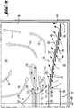
- Fig. 1A a total occupied by the reference numeral 10 apparatus for performing the method according to the invention.
- the apparatus 10 includes a container 20 having an upstanding cylindrical side wall 18 enclosing a process chamber 15.
- the process chamber 15 has a bottom 16, below which an inflow chamber 30 is located.
- the bottom 16 is composed of a total of seven annular superposed ring plates as baffles.
- the seven ring plates are superimposed so that an outermost ring plate 25 forms a lowermost ring plate on which then the other six inner ring plates, each lying underneath, partially overlapping, are placed.
- annular gap nozzle 50 is inserted in the central opening from below.
- the annular gap nozzle 50 has an orifice 55 which has a total of three orifice gaps 52, 53 and 54. All three orifice gaps 52, 53 and 54 are aligned so that they approximately parallel to the bottom 16, so spray approximately horizontally with a 360 ° Um chargedswinkel.
- spray air is pressed out as a spray gas, through the middle gap 53, the solution to be sprayed.
- the annular gap nozzle 50 has a rod-shaped body 56 which extends downwards and contains the corresponding channels and supply lines, which are known per se and therefore not shown in the drawing.
- the annular gap nozzle 50 may, for example, be formed with a so-called rotary annular gap, in which walls of the channel through which the solution is sprayed rotate relative to one another in order to avoid clogging of the nozzle, so that over the 360 ° circumferential angle uniformly Gap 53 can be sprayed out.
- the annular gap nozzle 50 has a conical head 57 above the mouth gap 52.
- a frusto-conical wall 58 is present, which has numerous openings 59. Like from the Fig. 1B can be seen, the bottom of the frusto-conical wall 58 rests on the innermost ring plate 29 such that between the bottom of the frusto-conical wall 58 and the underlying, with this partially overlapping ring plate 29, a slot 60 is formed to pass through the process air 40 therethrough can.
- the outer ring 25 is spaced from the wall 18 so that process air 40 can enter the process chamber 15 in the direction of the arrow indicated by the reference numeral 61 with a predominantly vertical component and thereby the process air 40 entering the process chamber 15 through the slots 28 gives relatively strong upward component.
- the process air 40 and the catalyst carrier moldings to be treated then separate from one another, with the process air 40 being discharged through outlets, while the mold bodies move radially downward in the direction of the conical head 57 of the annular gap nozzle 50 radially inwardly in the direction of the arrows 75.
- the moldings are deflected, passed to the top of the spray cloud 70 and treated there with the sprayed medium.
- the sprayed moldings then move in the direction of the Wall 18 and thereby away from each other, since after leaving the spray cloud 70 at the annular mouth gap 53, the moldings a circumferentially larger space is available.
- the shaped bodies to be treated meet with liquid particles and are moved away from one another in the direction of movement of the wall 18, thereby being treated very evenly and harmoniously with the process air 40 and thereby dried.
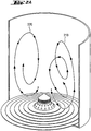
- FIG. 2A two possible trajectories of two elliptically encircling catalyst support shaped bodies are shown by means of the curve courses occupied by the reference numerals 210 and 220.
- the elliptical trajectory 210 has relatively large changes in major and minor axis size as compared to an ideal elliptical trajectory.
- the elliptical trajectory 220 in contrast, has relatively small changes in the size of the major and minor axes, and describes nearly an ideal elliptical trajectory without any circumferential (horizontal) motive component, as shown in FIG FIG. 2B can be seen.
- FIG. 3A a possible trajectory of a toroidally encircling catalyst carrier molded body is shown by means of the curve indicated by the reference numeral 310.
- the toroidal trajectory 310 describes a section of the surface of a nearly uniform torus whose vertical section is elliptical and whose horizontal section is annular.
- the FIG. 3B shows the movement path 310 in plan view.
Landscapes
- Chemical & Material Sciences (AREA)
- Organic Chemistry (AREA)
- Chemical Kinetics & Catalysis (AREA)
- Engineering & Computer Science (AREA)
- Materials Engineering (AREA)
- Catalysts (AREA)
- Organic Low-Molecular-Weight Compounds And Preparation Thereof (AREA)
- Low-Molecular Organic Synthesis Reactions Using Catalysts (AREA)
Claims (21)
- Procédé de fabrication d'un catalyseur à enveloppe, qui comprend un corps moulé support de catalyseur poreux muni d'une enveloppe extérieure, dans laquelle au moins une espèce catalytiquement active est contenue, le procédé étant réalisé en utilisant un dispositif (10) qui est conçu pour former un lit fluidisé de corps moulés supports de catalyseur au moyen d'un gaz de procédé (40), dans lequel les corps moulés supports de catalyseur sont mis en circulation sous une forme elliptique ou toroïdale, de préférence toroïdale, comprenant les étapes suivantes :a) le chargement du dispositif (10) avec des corps moulés supports de catalyseur poreux et la formation d'un lit fluidisé de corps moulés supports de catalyseur au moyen d'un gaz de procédé (40), les corps moulés supports de catalyseur étant mis en circulation sous forme elliptique ou toroïdale, de préférence toroïdale, dans le lit fluidisé ;b) la pulvérisation des corps moulés supports de catalyseur avec une solution contenant une espèce catalytiquement active ou un précurseur de celle-ci, les corps moulés supports de catalyseur étant mis en circulation sous forme elliptique ou toroïdale dans le lit fluidisé ;c) le séchage des corps moulés supports de catalyseur pulvérisés avec la solution.
- Procédé selon la revendication 1, caractérisé en ce que le procédé comprend en outre une étape de transformation du précurseur en une espèce catalytiquement active.
- Procédé selon l'une quelconque des revendications 1 ou 2, caractérisé en ce qu'un composant d'écoulement circonférentiel est appliqué à un gaz de procédé (40) introduit dans une chambre de procédé (15) du dispositif (10), par introduction d'un gaz de procédé supplémentaire (61) dans la chambre de procédé (15) au travers d'un fond (16) de la chambre de procédé (15) avec un composant de mouvement orienté en biais vers le haut, de préférence dans la zone d'une paroi latérale (18) de la chambre de procédé (15).
- Procédé selon l'une quelconque des revendications précédentes, caractérisé en ce que la pulvérisation des corps moulés supports de catalyseur en circulation sous forme elliptique ou toroïdal dans le lit fluidisé avec la solution est réalisée au moyen d'une buse à fente annulaire (50), qui pulvérise un nuage de pulvérisation (70), qui est parallèle au plan du fond (16) du dispositif (10) .
- Procédé selon l'une quelconque des revendications précédentes, caractérisé en ce que le gaz de procédé (40) est chauffé, de préférence à une température supérieure ou égale à 40 °C.
- Procédé selon l'une quelconque des revendications précédentes, caractérisé en ce que le gaz de procédé (40) est enrichi avec le solvant de la solution avant l'introduction dans la chambre de procédé (15), de préférence dans une plage allant de 10 à 50 % de la pression de vapeur de saturation.
- Procédé selon l'une quelconque des revendications précédentes, caractérisé en ce que la solution contient en tant qu'espèce catalytiquement active un biocatalyseur, de préférence une enzyme, ou contient en tant qu'espèce catalytiquement active ou en tant que précurseur de celle-ci un composé métallique d'un métal, choisi dans le groupe constitué par les métaux de transition, notamment les métaux nobles et Co, Ni et/ou Cu.
- Procédé selon la revendication 7, caractérisé en ce que la solution contient en tant qu'espèce catalytiquement active ou en tant que précurseur de celle-ci un composé de Pd et/ou un composé d'Au et/ou un composé d'Ag et/ou un composé de Pt.
- Procédé selon l'une quelconque des revendications précédentes, caractérisé en ce que le corps moulé support de catalyseur est soumis à une étape de fixation après la pulvérisation avec la solution.
- Catalyseur à enveloppe, pouvant être obtenu par un procédé selon l'une quelconque des revendications 1 à 9 ; comprenant un corps moulé support de catalyseur poreux muni d'une enveloppe extérieure, dans laquelle au moins une espèce catalytiquement active est contenue, caractérisé en ce que la concentration de l'espèce catalytiquement active diffère sur une zone de 90 % de l'épaisseur de l'enveloppe, la zone étant espacée à chaque fois de 5 % de l'épaisseur de l'enveloppe de la limite extérieure et de la limite intérieure de l'enveloppe, d'au plus ± 20 % de la concentration moyenne en espèce catalytiquement active de cette zone ; et
en ce que, sur l'épaisseur de l'enveloppe du catalyseur, la concentration maximale en espèce catalytiquement active se situe dans la zone de la limite extérieure de l'enveloppe et la concentration diminue dans la direction de la limite intérieure de l'enveloppe. - Catalyseur selon la revendication 10, caractérisé en ce que l'espèce catalytiquement active est un biocatalyseur, de préférence une enzyme, ou en ce que l'espèce catalytiquement active est un métal sous forme métallique, choisi dans le groupe constitué par les métaux de transition, de préférence dans le groupe constitué par les métaux nobles et Co, Ni et/ou Cu.
- Catalyseur selon l'une quelconque des revendications 10 à 11, caractérisé en ce que le catalyseur contient en tant qu'espèce catalytiquement active un, deux ou davantage de métaux différents les uns des autres dans l'enveloppe, notamment les métaux d'une des combinaisons suivantes : Pd et Ag ; Pd et Au ; Pd et Pt.
- Catalyseur selon l'une quelconque des revendications 10 à 12, caractérisé en ce que le catalyseur contient en tant qu'espèce catalytiquement active Pd et Au, et la proportion du catalyseur en Pd est de 0,6 à 2,0 % en masse, par rapport à la masse du support de catalyseur chargé avec un métal noble, et le rapport atomique Au/Pd du catalyseur est compris entre 0 et 1,2.
- Catalyseur selon l'une quelconque des revendications 10 à 13, caractérisé en ce que le catalyseur comprend un acétate de métal alcalin, de préférence l'acétate de potassium.
- Catalyseur selon l'une quelconque des revendications 10 à 14, caractérisé en ce que le support de catalyseur présente une surface inférieure ou égale à 160 m2/g.
- Catalyseur selon l'une quelconque des revendications 10 à 15, caractérisé en ce que le support de catalyseur présente une acidité comprise entre 1 et 150 pval/g.
- Catalyseur selon l'une quelconque des revendications 10 à 16, caractérisé en ce que le support de catalyseur est dopé avec au moins un oxyde d'un métal, choisi dans le groupe constitué par Zr, Hf, Ti, Nb, Ta, W, Mg, Re, Y et Fe, de préférence avec ZrO2, HfO2 ou Fe2O3.
- Catalyseur selon l'une quelconque des revendications 10 à 17, caractérisé en ce que le catalyseur contient en tant qu'espèce catalytiquement active Pd et Ag, et la proportion du catalyseur en Pd est de 0,01 à 1,0 % en masse, par rapport à la masse du support de catalyseur chargé avec un métal noble, le rapport atomique Ag/Pd du catalyseur étant compris entre 0 et 10, et l'épaisseur de l'enveloppe de métal noble étant de préférence inférieure à 60 µm.
- Catalyseur selon l'une quelconque des revendications 10 à 18, caractérisé en ce que le catalyseur contient en tant qu'espèce catalytiquement active Pd et Pt, et la proportion du catalyseur en Pd est de 0,05 à 5 % en masse, par rapport à la masse du support de catalyseur chargé avec un métal noble, le rapport atomique Pd/Pt du catalyseur étant compris entre 10 et 1.
- Catalyseur selon l'une quelconque des revendications 10 à 19, caractérisé en ce que l'enveloppe du catalyseur présente une épaisseur inférieure à 300 pm, ou en ce que l'enveloppe du catalyseur présente une épaisseur comprise entre 200 et 2 000 µm.
- Utilisation d'un dispositif (10) qui est conçu pour former un lit fluidisé de corps moulés supports de catalyseur au moyen d'un gaz de procédé (40), dans lequel les corps moulés supports de catalyseur sont mis en circulation sous forme elliptique ou toroïdale, de préférence toroïdale, pour la réalisation d'un procédé selon l'une quelconque des revendications 1 à 9 précédentes, ou lors de la fabrication d'un catalyseur à enveloppe selon l'une quelconque des revendications 10 à 20.
Applications Claiming Priority (2)
| Application Number | Priority Date | Filing Date | Title |
|---|---|---|---|
| DE102007025442.5A DE102007025442B4 (de) | 2007-05-31 | 2007-05-31 | Verwendung einer Vorrichtung zur Herstellung eines Schalenkatalysators und Schalenkatalysator |
| PCT/EP2008/004328 WO2008145388A1 (fr) | 2007-05-31 | 2008-05-30 | Procédé de production d'un catalyseur sous enveloppe et catalyseur sous enveloppe |
Publications (2)
| Publication Number | Publication Date |
|---|---|
| EP2155382A1 EP2155382A1 (fr) | 2010-02-24 |
| EP2155382B1 true EP2155382B1 (fr) | 2019-04-24 |
Family
ID=39683876
Family Applications (1)
| Application Number | Title | Priority Date | Filing Date |
|---|---|---|---|
| EP08758899.2A Active EP2155382B1 (fr) | 2007-05-31 | 2008-05-30 | Procédé de production d'un catalyseur sous enveloppe, catalyseur sous enveloppe et son utilisation |
Country Status (9)
| Country | Link |
|---|---|
| US (1) | US8927452B2 (fr) |
| EP (1) | EP2155382B1 (fr) |
| JP (2) | JP5539860B2 (fr) |
| KR (1) | KR20100047198A (fr) |
| CN (1) | CN101730587B (fr) |
| DE (1) | DE102007025442B4 (fr) |
| DK (1) | DK2155382T3 (fr) |
| MX (1) | MX2009013031A (fr) |
| WO (1) | WO2008145388A1 (fr) |
Families Citing this family (29)
| Publication number | Priority date | Publication date | Assignee | Title |
|---|---|---|---|---|
| DE102007025357A1 (de) * | 2007-05-31 | 2009-01-08 | Süd-Chemie AG | Verfahren zum Auftragen einer Washcoatsuspension auf eine Trägerstruktur |
| DE102007025442B4 (de) * | 2007-05-31 | 2023-03-02 | Clariant International Ltd. | Verwendung einer Vorrichtung zur Herstellung eines Schalenkatalysators und Schalenkatalysator |
| DE102007025223A1 (de) | 2007-05-31 | 2008-12-04 | Süd-Chemie AG | Zirkoniumoxid-dotierter VAM-Schalenkatalysator, Verfahren zu dessen Herstellung sowie dessen Verwendung |
| DE102008058971A1 (de) * | 2008-11-25 | 2010-07-15 | Süd-Chemie AG | Schalenkatalysator, Verfahren zu seiner Herstellung sowie Verwendung |
| DE102009051462B4 (de) * | 2009-10-30 | 2015-02-05 | Clariant International Ag | Verfahren zur Herstellung eines Kompositmaterials, Kompositmaterial und dessen Verwendung |
| DE102010026462A1 (de) * | 2010-07-08 | 2012-01-12 | Süd-Chemie AG | Verfahren zur Herstellung eines Schalenkatalysators und Schalenkatalysator |
| DE102011101459A1 (de) * | 2011-05-13 | 2012-11-15 | Süd-Chemie AG | Verfahren zur Herstellung eines metallhaltigen Schalenkatalysators ohne Zwischenkalzinierung |
| CN102861574B (zh) * | 2011-07-07 | 2015-07-01 | 中国石油化工股份有限公司 | 一种壳层催化剂及其制备方法 |
| US20130102819A1 (en) | 2011-10-19 | 2013-04-25 | Normen Szesni | Catalyst composition for selective hydrogenation with improved characteristics |
| DE102012003236A1 (de) * | 2012-02-20 | 2013-08-22 | Clariant Produkte (Deutschland) Gmbh | Vorvergoldung von Pd-Au-gecoateten Schalenkatalysatoren |
| DE102012003232A1 (de) * | 2012-02-20 | 2013-08-22 | Clariant Produkte (Deutschland) Gmbh | Nachvergoldung von Pd-Au-gecoateten Schalenkatalysatoren |
| FR2991197B1 (fr) * | 2012-05-31 | 2014-08-22 | IFP Energies Nouvelles | Catalyseur comprenant du palladium et de l'argent et son application en hydrogenation selective |
| DE102012008714A1 (de) * | 2012-05-03 | 2013-11-07 | Clariant Produkte (Deutschland) Gmbh | Vorimprägnierung von Schalenkatalysatoren mit einem Acetat |
| DE102012008715A1 (de) * | 2012-05-03 | 2013-11-07 | Clariant Produkte (Deutschland) Gmbh | Herstellung von Schalenkatalysatoren in einer Beschichtungsvorrichtung |
| FR2993795B1 (fr) * | 2012-07-25 | 2016-01-08 | IFP Energies Nouvelles | Procede de preparation de catalyseurs a base de particules metalliques de dispersion controlee |
| CN105612642B (zh) * | 2014-03-28 | 2019-03-05 | 恩亿凯嘉股份有限公司 | 电极用催化剂的制造方法 |
| CN105594047B (zh) * | 2014-03-28 | 2017-05-31 | 恩亿凯嘉股份有限公司 | 电极用催化剂的制造方法、电极用催化剂、气体扩散电极形成用组合物、气体扩散电极、膜/电极接合体(mea)以及燃料电池组 |
| RU2722157C1 (ru) * | 2015-07-22 | 2020-05-27 | Басф Корпорейшн | Катализаторы с высокой геометрической площадью поверхности для получения винилацетатного мономера |
| FR3051685B1 (fr) * | 2016-05-30 | 2018-06-08 | IFP Energies Nouvelles | Procede de preparation d'un catalyseur d'hydrogenation selective . |
| FR3059253B1 (fr) * | 2016-11-29 | 2020-01-17 | IFP Energies Nouvelles | Catalyseur d'hydrogenation selective d'une coupe d'hydrocarbures c3. |
| KR102250387B1 (ko) * | 2018-06-21 | 2021-05-10 | 주식회사 엘지화학 | 분리막 활성층의 제조 전 분리막 활성층을 구성하는 아민 화합물을 정량하는 방법, 분리막 활성층 중의 폴리아마이드 또는 미반응 아민 화합물을 정량하는 방법, 및 분리막 활성층의 제조 조건의 설정 기준 또는 제조 조건을 설정하는 방법 |
| JP2021528231A (ja) * | 2018-06-28 | 2021-10-21 | ダウ グローバル テクノロジーズ エルエルシー | 不均一触媒 |
| CN109331850B (zh) * | 2018-10-08 | 2021-07-23 | 万华化学集团股份有限公司 | 一种核壳型催化剂载体及一种涂层催化剂 |
| JP7548504B2 (ja) * | 2018-10-25 | 2024-09-10 | 学校法人早稲田大学 | 触媒付着体の製造方法及び製造装置、並びに、繊維状炭素ナノ構造体の製造方法及び製造装置 |
| KR102842971B1 (ko) * | 2019-07-25 | 2025-08-06 | 현대자동차주식회사 | 연료전지용 촉매 복합체, 이의 제조방법, 촉매 복합체를 포함하는 전해질막 및 이의 제조방법 |
| EP4201523A1 (fr) | 2021-12-21 | 2023-06-28 | Clariant International Ltd | Catalyseur sous enveloppe destiné à la production d'esters carboniques d'alcényle à distribution améliorée de pd |
| EP4201519A1 (fr) | 2021-12-21 | 2023-06-28 | Clariant International Ltd | Catalyseur sous enveloppe destiné à la production d'esters carboniques d'alcényle à distribution améliorée de pd et d'au |
| CN115624970B (zh) * | 2022-08-18 | 2024-05-07 | 扬州博克莱生物医药科技有限公司 | 一种用于微固定床连续液相加氢还原硝基化合物的催化剂及其制备方法和应用 |
| KR102933086B1 (ko) | 2024-04-19 | 2026-03-03 | 한국에너지기술연구원 | 에그쉘 구조 촉매의 제조방법 |
Family Cites Families (145)
| Publication number | Priority date | Publication date | Assignee | Title |
|---|---|---|---|---|
| GB585571A (en) | 1942-08-11 | 1947-02-12 | Standard Oil Dev Co | Improvements in or relating to the catalytic treatment of hydrocarbons |
| US2656323A (en) * | 1949-04-12 | 1953-10-20 | Universal Oil Prod Co | Manufacture of phosphoric acidgroup iv metal oxide containing catalyst |
| BE631220A (fr) * | 1962-04-20 | |||
| BE635482A (fr) * | 1962-07-27 | |||
| DE1286021B (de) | 1967-04-18 | 1969-01-02 | Knapsack Ag | Verfahren zur Herstellung von Estern von Carbonsaeuren mit ungesaettigten Alkoholen |
| FR1579327A (fr) * | 1967-09-07 | 1969-08-22 | ||
| GB1229749A (fr) | 1968-04-04 | 1971-04-28 | ||
| GB1283737A (en) | 1968-09-04 | 1972-08-02 | Nat Distillers Chem Corp | Method of catalyst preparation |
| US3617489A (en) * | 1969-06-25 | 1971-11-02 | Chevron Res | Hydrocracking catalyst comprising a layered clay-type crystalline aluminosilicate component, a group viii component and gold, process using said catalyst |
| GB1258371A (fr) | 1970-01-14 | 1971-12-30 | ||
| US3962135A (en) * | 1973-12-26 | 1976-06-08 | Filtrol Corporation | Shaped catalyst support |
| DE2703801C3 (de) * | 1977-01-29 | 1979-08-02 | W.C. Heraeus Gmbh, 6450 Hanau | Gegen glasige Schmelzen beständige Legierungen |
| DE2848978A1 (de) * | 1978-11-11 | 1980-05-22 | Bayer Ag | Traegerkatalysatoren, ihre herstellung und verwendung |
| DE2945913A1 (de) | 1979-11-14 | 1981-06-04 | Hoechst Ag, 6000 Frankfurt | Verfahren zur abtrennung von wasser aus gemischen mit vinylacetat und essigsaeure |
| FR2482953A1 (fr) | 1980-05-22 | 1981-11-27 | Inst Francais Du Petrole | Procede d'hydrogenation selective d'une di-olefine dans un melange d'hydrocarbures renfermant au moins 4 atomes de carbone et contenant une olefine -a |
| US4404124A (en) | 1981-05-06 | 1983-09-13 | Phillips Petroleum Company | Selective hydrogenation catalyst |
| DE3125062C2 (de) * | 1981-06-26 | 1984-11-22 | Degussa Ag, 6000 Frankfurt | Verfahren zur Herstellung von abriebfesten Schalenkatalysatoren und Verwendung eines so erhaltenen Katalysators |
| DE3532226A1 (de) | 1985-08-13 | 1987-03-19 | Sued Chemie Ag | Katalysator zur verringerung des stickoxidgehalts von verbrennungsabgasen |
| US4844790A (en) * | 1986-06-30 | 1989-07-04 | Union Oil Company Of California | Hydrocarbon conversion processes using delaminated clay catalysts |
| JPS6388040A (ja) | 1986-09-30 | 1988-04-19 | Nippon Engeruharudo Kk | 車輌用排気ガス浄化用触媒及びその製造方法 |
| US4977126A (en) * | 1987-05-07 | 1990-12-11 | Exxon Research And Engineering Company | Process for the preparation of surface impregnated dispersed cobalt metal catalysts |
| DE3830850A1 (de) * | 1988-09-10 | 1990-03-22 | Gutec Gmbh | Verfahren zur entfernung des nitrit- und/oder nitratgehaltes in wasser |
| US5213771A (en) * | 1988-10-31 | 1993-05-25 | Olin Corporation | Gas injector for hypochlorous acid reactor |
| DE3839723C1 (fr) | 1988-11-24 | 1989-07-20 | Herbert 7853 Steinen De Huettlin | |
| US5015453A (en) * | 1989-04-28 | 1991-05-14 | W. R. Grace & Co.-Conn. | Crystalline group IVA metal-containing molecular sieve compositions |
| DE3934614A1 (de) * | 1989-10-17 | 1991-04-18 | Hoechst Ag | Verfahren zur isolierung von vinylacetat |
| DE3938723A1 (de) * | 1989-11-23 | 1991-05-29 | Basf Ag | Katalysator zur herstellung von hochmolekularen homo- oder copolymerisaten des ethens sowie dessen herstellung |
| DE4000572C1 (fr) | 1990-01-10 | 1991-02-21 | Herbert 7853 Steinen De Huettlin | |
| DE4006935A1 (de) * | 1990-03-06 | 1991-09-12 | Wacker Chemie Gmbh | Fliessbettapparatur zum mischen, trocknen und beschichten von pulvrigem, koernigem und geformtem schuettgut |
| US5175136A (en) | 1990-05-31 | 1992-12-29 | Monsanto Company | Monolithic catalysts for conversion of sulfur dioxide to sulfur trioxide |
| DE4039026A1 (de) * | 1990-12-07 | 1992-06-11 | Bayer Ag | Verfahren zur herstellung von anilin |
| US5179056A (en) * | 1991-05-06 | 1993-01-12 | Union Carbide Chemicals & Plastics Technology Corporation | Production of alkenyl alkanoate catalysts |
| DE4120492A1 (de) * | 1991-06-21 | 1992-12-24 | Hoechst Ag | Verfahren zur herstellung von vinylacetat |
| TW330160B (en) * | 1992-04-08 | 1998-04-21 | Hoechst Ag | Supported catalyst, process for its preparation and its use for the preparation of vinyl acetate |
| US5248644A (en) * | 1992-04-13 | 1993-09-28 | Exxon Research And Engineering Company | Zirconia-pillared clays and micas |
| DE4217971C1 (de) * | 1992-05-30 | 1993-10-21 | Boehringer Ingelheim Vetmed | Verfahren und Wirbelbettapparatur zum Granulieren und/oder Umhüllen |
| US5369069A (en) * | 1992-10-20 | 1994-11-29 | Agency Of Industrial Science & Technology | Method for production of pillared clay having cation-exchange capacity |
| NO179131C (no) * | 1993-06-14 | 1996-08-14 | Statoil As | Katalysator, fremgangsmåte for dens fremstilling og fremgangsmåte for dehydrogenering av lette paraffiner |
| DE4323980C1 (de) | 1993-07-16 | 1995-03-30 | Hoechst Ag | Palladium und Kalium sowie Cadmium, Barium oder Gold enthaltender Schalenkatalysator, Verfahren zu dessen Herstellung sowie dessen Verwendung zur Herstellung von Vinylacetat |
| DE4323978C1 (de) | 1993-07-16 | 1995-02-16 | Hoechst Ag | Palladium und Kalium sowie Cadmium, Barium oder Gold enthaltender Schalenkatalysator, Verfahren zu dessen Herstellung sowie dessen Verwendung zur Herstellung von Vinylacetat |
| DE4323981C1 (de) * | 1993-07-16 | 1995-03-09 | Hoechst Ag | Palladium und Kalium sowie Cadmium, Barium oder Gold enthaltender Schalenkatalysator, Verfahren zu dessen Herstellung sowie dessen Verwendung zur Herstellung von Vinylacetat |
| CA2135021A1 (fr) * | 1993-11-19 | 1995-05-20 | David J. Gulliver | Procede pour la preparation de catalyseurs pour la production d'acetate de vinyle |
| US5466652A (en) * | 1994-02-22 | 1995-11-14 | The Standard Oil Co. | Process for the preparation of vinyl acetate catalyst |
| US6395676B2 (en) * | 1994-02-22 | 2002-05-28 | The Standard Oil Company | Process for the preparation of fluid bed vinyl acetate catalyst |
| DE4405876A1 (de) | 1994-02-23 | 1995-10-05 | Sued Chemie Ag | Katalysator- bzw. Katalysatorträger-Formkörper |
| JP3511067B2 (ja) * | 1994-04-29 | 2004-03-29 | 株式会社リコー | 小粒径粒子のコーティング方法 |
| JPH07303827A (ja) * | 1994-05-12 | 1995-11-21 | Ricoh Co Ltd | 流動層造粒装置 |
| US5665667A (en) * | 1994-06-02 | 1997-09-09 | The Standard Oil Company | Process for the preparation of vinyl acetate catalyst |
| EP0686615B2 (fr) * | 1994-06-09 | 2007-06-27 | Institut Francais Du Petrole | Procédé d'hydrogénation catalytique et catalyseur utilisable dans ce procédé |
| DE4443705A1 (de) | 1994-12-08 | 1996-06-13 | Studiengesellschaft Kohle Mbh | Verfahren zur Herstellung von tensidstabilisierten Mono- und Bimetallkolloiden der Gruppe VIII und Ib des Periodensystems als isolierbare und in hoher Konzentration wasserlösliche Precursor für Katalysatoren |
| US5753583A (en) * | 1995-01-09 | 1998-05-19 | Basf Aktiengesellschaft | Supported palladium catalyst |
| DE19501891C1 (de) * | 1995-01-23 | 1996-09-26 | Degussa | Verfahren zur Herstellung eines Trägerkatalysators und seine Verwendung für die Produktion von Vinylacetat |
| FR2742679B1 (fr) * | 1995-12-22 | 1998-01-16 | Inst Francais Du Petrole | Catalyseur d'hydrogenation selective et procede utilisant ce catalyseur |
| US5668074A (en) * | 1995-07-12 | 1997-09-16 | Phillips Petroleum Company | Preparation of catalysts for alkane/cycloalkane isomerization |
| DE19534493A1 (de) * | 1995-09-18 | 1997-03-20 | Basf Ag | Verfahren zur Herstellung feinteiliger Schalenkatalysatoren und ihre Verwendung bei der Synthese von Aziridinen |
| DE19538799A1 (de) | 1995-10-18 | 1997-04-24 | Sued Chemie Ag | Wabenförmiger Katalysatorträger |
| US6022823A (en) | 1995-11-07 | 2000-02-08 | Millennium Petrochemicals, Inc. | Process for the production of supported palladium-gold catalysts |
| US5650371A (en) * | 1995-12-26 | 1997-07-22 | Exxon Research And Engineering Company | Heterogeneous catalysts via impregnation process |
| DE19601861A1 (de) | 1996-01-19 | 1997-07-24 | Sued Chemie Ag | Kieselsäurehaltiger Katalysatorträger mit erhöhter Porosität |
| JP4067120B2 (ja) * | 1996-02-21 | 2008-03-26 | エイエスイーシー・マニュファクチュアリング | 排気転化触媒のための高度に分散した実質的に均一な混合した金属―酸化物複合担体 |
| US6207610B1 (en) * | 1996-05-17 | 2001-03-27 | Degussa-Huls Ag | Compacts based on pyrogenically produced silicon dioxide |
| SA97180048B1 (ar) | 1996-05-24 | 2005-12-21 | هوكست سيلانس كوربوريشن | محفز بلاديوم - ذهب palladium gold ثنائي المعدن متغاير الخواص heterogeneous bimetallic vinyl acetate لإنتاج أسيتات فينيل |
| EP0917532B1 (fr) * | 1996-07-01 | 2002-02-13 | The Dow Chemical Company | Procede pour oxyder directement les olefines en oxydes d'olefines |
| US5935889A (en) * | 1996-10-04 | 1999-08-10 | Abb Lummus Global Inc. | Catalyst and method of preparation |
| GB9622911D0 (en) | 1996-11-04 | 1997-01-08 | Bp Chem Int Ltd | Process |
| DE19645549A1 (de) | 1996-11-05 | 1998-05-07 | Bayer Ag | Verfahren zur Herstellung von 2-Methyl-2,4-diaminopentan |
| TW377306B (en) * | 1996-12-16 | 1999-12-21 | Asahi Chemical Ind | Noble metal support |
| US6075101A (en) | 1997-02-19 | 2000-06-13 | Union Carbide Chemicals & Plastics Technology Corporation | Control of solution catalyst droplet size with a perpendicular spray nozzle |
| US5888472A (en) * | 1997-04-08 | 1999-03-30 | Uop Llc | Zirconium silicate molecular sieves and process using the same |
| DE19721601A1 (de) * | 1997-05-23 | 1998-11-26 | Hoechst Ag | Polybetain-stabilisierte, Palladium-haltige Nanopartikel, ein Verfahren zu ihrer Herstellung sowie daraus hergestellte Katalysatoren zur Gewinnung von Vinylacetat |
| DE19723591A1 (de) * | 1997-06-05 | 1998-12-10 | Hoechst Ag | Katalysator, Verfahren zu seiner Herstellung und seine Verwendung zur Herstellung von Vinylacetat |
| JPH11561A (ja) * | 1997-06-13 | 1999-01-06 | Tonen Corp | 重質油の接触分解用添加触媒 |
| DE19734975A1 (de) | 1997-08-13 | 1999-03-11 | Hoechst Ag | Schalenkatalysator, Verfahren zu dessen Herstellung sowie Verwendung, insbesondere zur Gasphasenoxidation von Ethylen und Essigsäure zu Vinylacetat |
| DE19734974A1 (de) | 1997-08-13 | 1999-02-25 | Hoechst Ag | Verfahren zur Herstellung von porös geträgerten Metall-Nanopartikel-haltigen Katalysatoren, insbesondere für die Gasphasenoxidation von Ethylen und Essigsäure zu Vinylacetat |
| FR2767722B1 (fr) | 1997-08-29 | 1999-12-31 | Inst Francais Du Petrole | Nouveau catalyseur utilisable dans les reactions de transformation de composes organiques |
| DE19743100A1 (de) * | 1997-09-30 | 1999-04-01 | Degussa | Verfahren zur Herstellung eines Schalenkatalysators |
| US5883035A (en) | 1997-11-05 | 1999-03-16 | Engelhard Corporation | Mesoporous silicoaluminate products and production thereof by controlled acid extraction of aluminum from calcium bentonite clay |
| DE19750238A1 (de) * | 1997-11-13 | 1999-05-27 | Degussa | Preßlinge auf Basis von pyrogen hergestelltem Siliciumdioxid |
| JP2003535016A (ja) | 1998-02-05 | 2003-11-25 | エンゲルハード・コーポレーシヨン | 酢酸ビニル単量体用pd−au触媒の老化抑制 |
| GB9807498D0 (en) | 1998-04-08 | 1998-06-10 | Ici Plc | Production of unsaturated acids therfore and catalysts therfor |
| US6017847A (en) | 1998-06-02 | 2000-01-25 | Celanese International Corporation | Vinyl acetate catalyst prepared with potassium aurate and comprising metallic palladium and gold on a carrier precoated with copper |
| ID26891A (id) | 1998-06-02 | 2001-02-15 | Celanese Internasional Corp | Katalis vinil asetat yang terdiri dari palladium logam dan emas yang dibuat dengan potasium aurat |
| US6015769A (en) * | 1998-06-02 | 2000-01-18 | Celanese International Corporation | Vinyl acetate catalyst comprising metallic palladium, gold and copper supported on a carrier and prepared with potassium aurate |
| DE19824532A1 (de) * | 1998-06-03 | 1999-12-09 | Basf Ag | Verfahren zur Herstellung von Schalenkatalysatoren für die katalytische Gasphasenoxidation von aromatischen Kohlenwasserstoffen und so erhältliche Katalysatoren |
| DE19827844A1 (de) | 1998-06-23 | 1999-12-30 | Aventis Res & Tech Gmbh & Co | Verfahren zur Herstellung von Schalenkatalysatoren durch CVD-Beschichtung |
| DE19828491A1 (de) * | 1998-06-26 | 1999-12-30 | Degussa | Formkörper auf Basis von Siliciumdioxid |
| DE19834569A1 (de) | 1998-07-31 | 2000-02-03 | Celanese Chem Europe Gmbh | Verfahren zur Herstellung von Trägerkatalysatoren sowie deren Verwendung für die Herstellung von Vinylacetatmonomer |
| DE19840373A1 (de) * | 1998-09-04 | 2000-03-09 | Basf Ag | Katalysator und Verfahren zur Selektivhydrierung ungesättigter Verbindungen in Kohlenwasserstoffströmen |
| DE19843693A1 (de) | 1998-09-24 | 2000-03-30 | Degussa | Trägerkatalysator für die Produktion von Vinylacetatmonomer |
| US6358882B1 (en) * | 1998-12-08 | 2002-03-19 | The Standard Oil Company | Fluid bed vinyl acetate catalyst |
| DE19904147C2 (de) * | 1999-02-03 | 2001-05-10 | Herbert Huettlin | Vorrichtung zum Behandeln von partikelförmigem Gut |
| DE19914066A1 (de) | 1999-03-27 | 2000-10-05 | Celanese Chem Europe Gmbh | Katalysatoren für die Gasphasenoxidation von Ethylen und Essigsäure zu Vinylacetat, Verfahren zu ihrer Herstellung und ihre Verwendung |
| US6143921A (en) * | 1999-05-14 | 2000-11-07 | Saudi Basic Industries Corporation | Method for producing vinyl acetate monomer from ethane or ethylene oxidation |
| JP2000354770A (ja) * | 1999-06-14 | 2000-12-26 | Nikki Chemcal Co Ltd | 活性成分の担持方法 |
| JP2001255358A (ja) * | 2000-03-10 | 2001-09-21 | Sumitomo Electric Ind Ltd | 磁気センサ |
| DE10015250A1 (de) | 2000-03-28 | 2001-10-04 | Basf Ag | Schalenkatalysator für die Gasphasenhydrierung |
| US6420308B1 (en) * | 2000-07-07 | 2002-07-16 | Saudi Basic Industries Corp | Highly selective shell impregnated catalyst of improved space time yield for production of vinyl acetate |
| US6534438B1 (en) * | 2000-07-26 | 2003-03-18 | Bp Chemicals Limited | Catalyst composition |
| DE10064084B4 (de) | 2000-12-21 | 2005-09-29 | Wacker-Chemie Gmbh | Verfahren zur Herstellung von Vinylacetat |
| US6797669B2 (en) * | 2000-12-29 | 2004-09-28 | China Petroleum & Chemical Corporation | Catalyst for selective hydrogenation, its preparation process and application |
| JP3652618B2 (ja) * | 2001-03-29 | 2005-05-25 | 株式会社日本触媒 | 排水の処理方法 |
| JP2002292266A (ja) * | 2001-03-30 | 2002-10-08 | Okawara Mfg Co Ltd | 被処理物の流動を促進させた流動層造粒乾燥装置 |
| US6734131B2 (en) * | 2001-04-30 | 2004-05-11 | W. R. Grace & Co.-Conn. | Heterogeneous chromium catalysts and processes of polymerization of olefins using same |
| CA2446970C (fr) * | 2001-05-10 | 2012-09-25 | Akzo Nobel Nv | Procede continu et appareil de conversion efficiente de particules solides inorganiques |
| FR2825296B1 (fr) * | 2001-05-30 | 2003-09-12 | Toulouse Inst Nat Polytech | Procede de fabrication de nanoparticules metalliques supportees en lit fluidise |
| DE10129166C1 (de) * | 2001-06-12 | 2003-01-16 | Herbert Huettlin | Vorrichtung zum Behandeln von partikelförmigem Gut |
| CN1281720C (zh) * | 2001-10-15 | 2006-10-25 | 催化蒸馏技术公司 | 加氢催化剂和加氢方法 |
| DE10163180A1 (de) * | 2001-12-21 | 2003-07-10 | Degussa | Trägerkatalysator |
| JP4421201B2 (ja) * | 2002-03-27 | 2010-02-24 | シエル・インターナシヨナル・リサーチ・マートスハツペイ・ベー・ヴエー | 触媒を調製する方法、触媒、および触媒の使用 |
| US6822008B2 (en) * | 2002-09-06 | 2004-11-23 | Conocophillips Company | Fischer-Tropsch catalysts using multiple precursors |
| DE10248116B3 (de) | 2002-10-07 | 2004-04-15 | Hüttlin, Herbert, Dr.h.c. | Vorrichtung zum Behandeln von partikelförmigem Gut mit einer Höhenverstellvorrichtung |
| JP3951127B2 (ja) | 2003-02-28 | 2007-08-01 | 国立大学法人静岡大学 | ジメチルエーテル水蒸気改質触媒およびその製造方法 |
| US7569508B2 (en) * | 2004-11-17 | 2009-08-04 | Headwaters Technology Innovation, Llc | Reforming nanocatalysts and method of making and using such catalysts |
| CN1859973B (zh) * | 2003-09-26 | 2010-06-16 | 巴斯福股份公司 | 通过在流化床装置中涂覆载体材料生产气相氧化催化剂的方法 |
| DE10344845A1 (de) * | 2003-09-26 | 2005-04-14 | Basf Ag | Vorrichtung zum Mischen, Trocknen und Beschichten von pulvrigem, körnigem oder geformtem Schüttgut in einem Fließbett und Verfahren zur Herstellung von Trägerkatalysatoren unter Verwendung einer solchen Vorrichtung |
| BRPI0416406A (pt) | 2003-12-19 | 2007-01-09 | Celanese Int Corp | método para produzir um catalisador ou pré-catalisador adequado para auxiliar na produção de alcanoatos de alquenila, composição para catalisar a produção de um alcanoato de alquenila e método de produção de alcanoatos de alquenila |
| TW201236755A (en) * | 2003-12-19 | 2012-09-16 | Celanese Int Corp | Halide free precursors for catalysts |
| AU2004305515C1 (en) | 2003-12-19 | 2009-06-25 | Celanese International Corporation | Zirconia containing support material for catalysts |
| JP4452097B2 (ja) | 2004-03-03 | 2010-04-21 | 出光興産株式会社 | 酸化セリウム成形体の製造方法 |
| US7235507B2 (en) * | 2004-08-14 | 2007-06-26 | Sud-Chemie Inc. | Catalyst for purifying diesel engine exhaust emissions |
| JP4347162B2 (ja) * | 2004-08-24 | 2009-10-21 | 東京瓦斯株式会社 | 炭化水素の水蒸気改質触媒及びその製造方法 |
| DE502004006231D1 (de) | 2004-09-10 | 2008-03-27 | Huettlin Herbert | Vorrichtung zum behandeln von partikelförmigem gut |
| DE202005003791U1 (de) | 2005-02-28 | 2006-07-06 | Hüttlin, Herbert, Dr. h.c. | Apparatur zur Behandlung von partikelförmigem Gut |
| US7713910B2 (en) | 2004-10-29 | 2010-05-11 | Umicore Ag & Co Kg | Method for manufacture of noble metal alloy catalysts and catalysts prepared therewith |
| US7468455B2 (en) | 2004-11-03 | 2008-12-23 | Velocys, Inc. | Process and apparatus for improved methods for making vinyl acetate monomer (VAM) |
| ZA200704864B (en) * | 2004-12-20 | 2008-08-27 | Celanese Int Corp | Modified support materials for catalysts |
| CN101146614A (zh) | 2005-01-20 | 2008-03-19 | 苏德-化学公司 | 加氢催化剂 |
| FR2882531B1 (fr) * | 2005-02-25 | 2007-04-27 | Inst Francais Du Petrole | Procede de preparation de catalyseurs multimetalliques utilisables dans des reactions de transformation des hydrocarbures |
| JP4717474B2 (ja) * | 2005-03-03 | 2011-07-06 | コスモ石油株式会社 | 炭化水素からの水素製造用触媒、該触媒の製造法、及び該触媒を用いた水素製造法 |
| JP5011646B2 (ja) * | 2005-03-17 | 2012-08-29 | 東ソー株式会社 | 硫酸化酸化鉄を含む新規な構造体、およびその製造方法。 |
| US7638459B2 (en) * | 2005-05-25 | 2009-12-29 | Uop Llc | Layered composition and processes for preparing and using the composition |
| DE102005029200A1 (de) | 2005-06-22 | 2006-12-28 | Basf Ag | Katalysator und Verfahren zur Hydrierung von hydrierbare Gruppen enthaltenden organischen Verbindungen |
| US20070148068A1 (en) | 2005-12-23 | 2007-06-28 | Burgers Kenneth L | Reclaiming amines in carbon dioxide recovery |
| WO2007092367A2 (fr) | 2006-02-03 | 2007-08-16 | Saint-Gobain Ceramics & Plastics, Inc. | Articles comprenant de la zircone tétragonale et leurs procédés de fabrication |
| EP1967249A1 (fr) | 2007-03-05 | 2008-09-10 | RWE Power Aktiengesellschaft | Procédé basé sur la distillation diphasique destiné à l'utilisation de chaleur à basse température pour la régénération de solvants CO2 lors de la séparation du CO2 contenu dans des fumèes à l'aide d'un lavage de CO2 |
| DE102007025443A1 (de) | 2007-05-31 | 2008-12-04 | Süd-Chemie AG | Pd/Au-Schalenkatalysator enthaltend HfO2, Verfahren zu dessen Herstellung sowie dessen Verwendung |
| DE102007025442B4 (de) * | 2007-05-31 | 2023-03-02 | Clariant International Ltd. | Verwendung einer Vorrichtung zur Herstellung eines Schalenkatalysators und Schalenkatalysator |
| DE102007025223A1 (de) | 2007-05-31 | 2008-12-04 | Süd-Chemie AG | Zirkoniumoxid-dotierter VAM-Schalenkatalysator, Verfahren zu dessen Herstellung sowie dessen Verwendung |
| DE102007025444A1 (de) * | 2007-05-31 | 2008-12-11 | Süd-Chemie AG | VAM-Schalenkatalysator, Verfahren zu dessen Herstellung sowie dessen Verwendung |
| EP2200736B1 (fr) * | 2007-10-08 | 2016-11-30 | Basf Se | Procédé de préparation de corps façonnés dotés de propriétés catalytiques comme éléments de réacteur |
| US20110117289A1 (en) * | 2007-12-28 | 2011-05-19 | Ulvac, Inc. | Deposition Apparatus and Deposition Method |
| US20100140181A1 (en) * | 2008-12-05 | 2010-06-10 | Gilles Tastayre | Regeneration of used cleaning solution |
| US20110017289A1 (en) | 2009-07-24 | 2011-01-27 | Electronics And Telecommunications Research Institute | Cigs solar cell and method of fabricating the same |
| KR101081294B1 (ko) | 2009-10-07 | 2011-11-08 | 엘지이노텍 주식회사 | 태양전지 및 이의 제조방법 |
| KR101091215B1 (ko) | 2009-10-30 | 2011-12-07 | 엘지이노텍 주식회사 | 태양전지 및 이의 제조방법 |
-
2007
- 2007-05-31 DE DE102007025442.5A patent/DE102007025442B4/de active Active
-
2008
- 2008-05-30 US US12/601,777 patent/US8927452B2/en active Active
- 2008-05-30 EP EP08758899.2A patent/EP2155382B1/fr active Active
- 2008-05-30 MX MX2009013031A patent/MX2009013031A/es unknown
- 2008-05-30 DK DK08758899.2T patent/DK2155382T3/da active
- 2008-05-30 WO PCT/EP2008/004328 patent/WO2008145388A1/fr not_active Ceased
- 2008-05-30 JP JP2010509740A patent/JP5539860B2/ja not_active Expired - Fee Related
- 2008-05-30 CN CN2008800180346A patent/CN101730587B/zh active Active
- 2008-05-30 KR KR1020097027577A patent/KR20100047198A/ko not_active Withdrawn
-
2013
- 2013-09-30 JP JP2013205853A patent/JP5695152B2/ja not_active Expired - Fee Related
Non-Patent Citations (1)
| Title |
|---|
| None * |
Also Published As
| Publication number | Publication date |
|---|---|
| CN101730587A (zh) | 2010-06-09 |
| JP5695152B2 (ja) | 2015-04-01 |
| EP2155382A1 (fr) | 2010-02-24 |
| MX2009013031A (es) | 2010-05-21 |
| KR20100047198A (ko) | 2010-05-07 |
| DK2155382T3 (da) | 2019-07-15 |
| US8927452B2 (en) | 2015-01-06 |
| JP5539860B2 (ja) | 2014-07-02 |
| JP2014065036A (ja) | 2014-04-17 |
| DE102007025442B4 (de) | 2023-03-02 |
| WO2008145388A1 (fr) | 2008-12-04 |
| JP2010527777A (ja) | 2010-08-19 |
| CN101730587B (zh) | 2013-08-21 |
| DE102007025442A1 (de) | 2008-12-11 |
| US20100197488A1 (en) | 2010-08-05 |
Similar Documents
| Publication | Publication Date | Title |
|---|---|---|
| EP2155382B1 (fr) | Procédé de production d'un catalyseur sous enveloppe, catalyseur sous enveloppe et son utilisation | |
| DE102007025356A1 (de) | Verfahren zur Herstellung eines Schalenkatalysators und Schalenkatalysator | |
| EP2158035B1 (fr) | Support de catalyseur dopé à l'oxyde de zirconium, procédé de production dudit support de catalyseur et catalyseur contenant un support de catalyseur dopé à l'oxyde de zirconium | |
| EP1278600B1 (fr) | Catalyseurs a coque, leur procede de production et leur utilisation | |
| EP2155380A2 (fr) | Catalyseur sous enveloppe servant à la production de vam, procédé de production et d'utilisation dudit catalyseur | |
| DE102010026462A1 (de) | Verfahren zur Herstellung eines Schalenkatalysators und Schalenkatalysator | |
| DE102007025362A1 (de) | Dotierter Pd/Au-Schalenkatalysator, Verfahren zu dessen Herstellung sowie dessen Verwendung | |
| WO2008145392A2 (fr) | CATALYSEUR SOUS ENVELOPPE Pd/Au À TENEUR EN HfO2, PROCÉDÉ DE PRODUCTION ET D'UTILISATION DUDIT CATALYSEUR | |
| BE1019001A5 (de) | Schalenkatalysator, verfahren zu seiner herstellung sowie verwendung. | |
| DE102012008714A1 (de) | Vorimprägnierung von Schalenkatalysatoren mit einem Acetat | |
| DE102011101459A1 (de) | Verfahren zur Herstellung eines metallhaltigen Schalenkatalysators ohne Zwischenkalzinierung | |
| WO2010060649A2 (fr) | Catalyseur à enveloppe, procédé de production dudit catalyseur et son utilisation | |
| EP2817094B1 (fr) | Prédorure de catalyseurs enrobés revêtus de pd-au | |
| WO2008151731A1 (fr) | Procédé de production d'un catalyseur sous enveloppe à l'aide d'un mélange basique ou acide | |
| DE102012003232A1 (de) | Nachvergoldung von Pd-Au-gecoateten Schalenkatalysatoren | |
| WO2008145386A2 (fr) | Procédé de production d'un catalyseur sous enveloppe | |
| EP4201519A1 (fr) | Catalyseur sous enveloppe destiné à la production d'esters carboniques d'alcényle à distribution améliorée de pd et d'au | |
| EP4201523A1 (fr) | Catalyseur sous enveloppe destiné à la production d'esters carboniques d'alcényle à distribution améliorée de pd | |
| DE102011018532A1 (de) | Basische Katalysatorträgerkörper mit niedriger Oberfläche |
Legal Events
| Date | Code | Title | Description |
|---|---|---|---|
| PUAI | Public reference made under article 153(3) epc to a published international application that has entered the european phase |
Free format text: ORIGINAL CODE: 0009012 |
|
| 17P | Request for examination filed |
Effective date: 20091223 |
|
| AK | Designated contracting states |
Kind code of ref document: A1 Designated state(s): AT BE BG CH CY CZ DE DK EE ES FI FR GB GR HR HU IE IS IT LI LT LU LV MC MT NL NO PL PT RO SE SI SK TR |
|
| AX | Request for extension of the european patent |
Extension state: AL BA MK RS |
|
| DAX | Request for extension of the european patent (deleted) | ||
| 17Q | First examination report despatched |
Effective date: 20100813 |
|
| RAP1 | Party data changed (applicant data changed or rights of an application transferred) |
Owner name: SUED-CHEMIE IP GMBH & CO. KG |
|
| STAA | Information on the status of an ep patent application or granted ep patent |
Free format text: STATUS: EXAMINATION IS IN PROGRESS |
|
| RAP1 | Party data changed (applicant data changed or rights of an application transferred) |
Owner name: SUED-CHEMIE IP GMBH & CO. KG |
|
| GRAP | Despatch of communication of intention to grant a patent |
Free format text: ORIGINAL CODE: EPIDOSNIGR1 |
|
| STAA | Information on the status of an ep patent application or granted ep patent |
Free format text: STATUS: GRANT OF PATENT IS INTENDED |
|
| INTG | Intention to grant announced |
Effective date: 20181129 |
|
| GRAS | Grant fee paid |
Free format text: ORIGINAL CODE: EPIDOSNIGR3 |
|
| GRAA | (expected) grant |
Free format text: ORIGINAL CODE: 0009210 |
|
| STAA | Information on the status of an ep patent application or granted ep patent |
Free format text: STATUS: THE PATENT HAS BEEN GRANTED |
|
| AK | Designated contracting states |
Kind code of ref document: B1 Designated state(s): AT BE BG CH CY CZ DE DK EE ES FI FR GB GR HR HU IE IS IT LI LT LU LV MC MT NL NO PL PT RO SE SI SK TR |
|
| REG | Reference to a national code |
Ref country code: GB Ref legal event code: FG4D Free format text: NOT ENGLISH |
|
| REG | Reference to a national code |
Ref country code: CH Ref legal event code: EP |
|
| REG | Reference to a national code |
Ref country code: AT Ref legal event code: REF Ref document number: 1123478 Country of ref document: AT Kind code of ref document: T Effective date: 20190515 Ref country code: IE Ref legal event code: FG4D Free format text: LANGUAGE OF EP DOCUMENT: GERMAN |
|
| REG | Reference to a national code |
Ref country code: DE Ref legal event code: R096 Ref document number: 502008016723 Country of ref document: DE |
|
| REG | Reference to a national code |
Ref country code: DK Ref legal event code: T3 Effective date: 20190711 |
|
| REG | Reference to a national code |
Ref country code: NL Ref legal event code: FP |
|
| REG | Reference to a national code |
Ref country code: LT Ref legal event code: MG4D |
|
| PG25 | Lapsed in a contracting state [announced via postgrant information from national office to epo] |
Ref country code: LT Free format text: LAPSE BECAUSE OF FAILURE TO SUBMIT A TRANSLATION OF THE DESCRIPTION OR TO PAY THE FEE WITHIN THE PRESCRIBED TIME-LIMIT Effective date: 20190424 Ref country code: FI Free format text: LAPSE BECAUSE OF FAILURE TO SUBMIT A TRANSLATION OF THE DESCRIPTION OR TO PAY THE FEE WITHIN THE PRESCRIBED TIME-LIMIT Effective date: 20190424 Ref country code: NO Free format text: LAPSE BECAUSE OF FAILURE TO SUBMIT A TRANSLATION OF THE DESCRIPTION OR TO PAY THE FEE WITHIN THE PRESCRIBED TIME-LIMIT Effective date: 20190724 Ref country code: SE Free format text: LAPSE BECAUSE OF FAILURE TO SUBMIT A TRANSLATION OF THE DESCRIPTION OR TO PAY THE FEE WITHIN THE PRESCRIBED TIME-LIMIT Effective date: 20190424 Ref country code: HR Free format text: LAPSE BECAUSE OF FAILURE TO SUBMIT A TRANSLATION OF THE DESCRIPTION OR TO PAY THE FEE WITHIN THE PRESCRIBED TIME-LIMIT Effective date: 20190424 Ref country code: ES Free format text: LAPSE BECAUSE OF FAILURE TO SUBMIT A TRANSLATION OF THE DESCRIPTION OR TO PAY THE FEE WITHIN THE PRESCRIBED TIME-LIMIT Effective date: 20190424 Ref country code: PT Free format text: LAPSE BECAUSE OF FAILURE TO SUBMIT A TRANSLATION OF THE DESCRIPTION OR TO PAY THE FEE WITHIN THE PRESCRIBED TIME-LIMIT Effective date: 20190824 |
|
| PG25 | Lapsed in a contracting state [announced via postgrant information from national office to epo] |
Ref country code: GR Free format text: LAPSE BECAUSE OF FAILURE TO SUBMIT A TRANSLATION OF THE DESCRIPTION OR TO PAY THE FEE WITHIN THE PRESCRIBED TIME-LIMIT Effective date: 20190725 Ref country code: BG Free format text: LAPSE BECAUSE OF FAILURE TO SUBMIT A TRANSLATION OF THE DESCRIPTION OR TO PAY THE FEE WITHIN THE PRESCRIBED TIME-LIMIT Effective date: 20190724 Ref country code: LV Free format text: LAPSE BECAUSE OF FAILURE TO SUBMIT A TRANSLATION OF THE DESCRIPTION OR TO PAY THE FEE WITHIN THE PRESCRIBED TIME-LIMIT Effective date: 20190424 Ref country code: PL Free format text: LAPSE BECAUSE OF FAILURE TO SUBMIT A TRANSLATION OF THE DESCRIPTION OR TO PAY THE FEE WITHIN THE PRESCRIBED TIME-LIMIT Effective date: 20190424 |
|
| REG | Reference to a national code |
Ref country code: CH Ref legal event code: PL |
|
| PG25 | Lapsed in a contracting state [announced via postgrant information from national office to epo] |
Ref country code: IS Free format text: LAPSE BECAUSE OF FAILURE TO SUBMIT A TRANSLATION OF THE DESCRIPTION OR TO PAY THE FEE WITHIN THE PRESCRIBED TIME-LIMIT Effective date: 20190824 |
|
| REG | Reference to a national code |
Ref country code: DE Ref legal event code: R097 Ref document number: 502008016723 Country of ref document: DE |
|
| PG25 | Lapsed in a contracting state [announced via postgrant information from national office to epo] |
Ref country code: CH Free format text: LAPSE BECAUSE OF NON-PAYMENT OF DUE FEES Effective date: 20190531 Ref country code: SK Free format text: LAPSE BECAUSE OF FAILURE TO SUBMIT A TRANSLATION OF THE DESCRIPTION OR TO PAY THE FEE WITHIN THE PRESCRIBED TIME-LIMIT Effective date: 20190424 Ref country code: MC Free format text: LAPSE BECAUSE OF FAILURE TO SUBMIT A TRANSLATION OF THE DESCRIPTION OR TO PAY THE FEE WITHIN THE PRESCRIBED TIME-LIMIT Effective date: 20190424 Ref country code: CZ Free format text: LAPSE BECAUSE OF FAILURE TO SUBMIT A TRANSLATION OF THE DESCRIPTION OR TO PAY THE FEE WITHIN THE PRESCRIBED TIME-LIMIT Effective date: 20190424 Ref country code: LI Free format text: LAPSE BECAUSE OF NON-PAYMENT OF DUE FEES Effective date: 20190531 Ref country code: EE Free format text: LAPSE BECAUSE OF FAILURE TO SUBMIT A TRANSLATION OF THE DESCRIPTION OR TO PAY THE FEE WITHIN THE PRESCRIBED TIME-LIMIT Effective date: 20190424 Ref country code: RO Free format text: LAPSE BECAUSE OF FAILURE TO SUBMIT A TRANSLATION OF THE DESCRIPTION OR TO PAY THE FEE WITHIN THE PRESCRIBED TIME-LIMIT Effective date: 20190424 |
|
| REG | Reference to a national code |
Ref country code: BE Ref legal event code: MM Effective date: 20190531 |
|
| PG25 | Lapsed in a contracting state [announced via postgrant information from national office to epo] |
Ref country code: LU Free format text: LAPSE BECAUSE OF NON-PAYMENT OF DUE FEES Effective date: 20190530 |
|
| PLBE | No opposition filed within time limit |
Free format text: ORIGINAL CODE: 0009261 |
|
| STAA | Information on the status of an ep patent application or granted ep patent |
Free format text: STATUS: NO OPPOSITION FILED WITHIN TIME LIMIT |
|
| PG25 | Lapsed in a contracting state [announced via postgrant information from national office to epo] |
Ref country code: TR Free format text: LAPSE BECAUSE OF FAILURE TO SUBMIT A TRANSLATION OF THE DESCRIPTION OR TO PAY THE FEE WITHIN THE PRESCRIBED TIME-LIMIT Effective date: 20190424 |
|
| 26N | No opposition filed |
Effective date: 20200127 |
|
| PG25 | Lapsed in a contracting state [announced via postgrant information from national office to epo] |
Ref country code: IE Free format text: LAPSE BECAUSE OF NON-PAYMENT OF DUE FEES Effective date: 20190530 |
|
| PG25 | Lapsed in a contracting state [announced via postgrant information from national office to epo] |
Ref country code: BE Free format text: LAPSE BECAUSE OF NON-PAYMENT OF DUE FEES Effective date: 20190531 Ref country code: SI Free format text: LAPSE BECAUSE OF FAILURE TO SUBMIT A TRANSLATION OF THE DESCRIPTION OR TO PAY THE FEE WITHIN THE PRESCRIBED TIME-LIMIT Effective date: 20190424 |
|
| REG | Reference to a national code |
Ref country code: AT Ref legal event code: MM01 Ref document number: 1123478 Country of ref document: AT Kind code of ref document: T Effective date: 20190530 |
|
| PG25 | Lapsed in a contracting state [announced via postgrant information from national office to epo] |
Ref country code: AT Free format text: LAPSE BECAUSE OF NON-PAYMENT OF DUE FEES Effective date: 20190530 |
|
| REG | Reference to a national code |
Ref country code: DE Ref legal event code: R081 Ref document number: 502008016723 Country of ref document: DE Owner name: CLARIANT INTERNATIONAL LTD., CH Free format text: FORMER OWNER: SUED-CHEMIE IP GMBH & CO. KG, 81925 MUENCHEN, DE |
|
| PG25 | Lapsed in a contracting state [announced via postgrant information from national office to epo] |
Ref country code: CY Free format text: LAPSE BECAUSE OF FAILURE TO SUBMIT A TRANSLATION OF THE DESCRIPTION OR TO PAY THE FEE WITHIN THE PRESCRIBED TIME-LIMIT Effective date: 20190424 |
|
| REG | Reference to a national code |
Ref country code: NL Ref legal event code: PD Owner name: CLARIANT INTERNATIONAL LTD; CH Free format text: DETAILS ASSIGNMENT: CHANGE OF OWNER(S), ASSIGNMENT; FORMER OWNER NAME: SUED-CHEMIE IP GMBH & CO. KG Effective date: 20210628 |
|
| PG25 | Lapsed in a contracting state [announced via postgrant information from national office to epo] |
Ref country code: MT Free format text: LAPSE BECAUSE OF FAILURE TO SUBMIT A TRANSLATION OF THE DESCRIPTION OR TO PAY THE FEE WITHIN THE PRESCRIBED TIME-LIMIT Effective date: 20190424 Ref country code: HU Free format text: LAPSE BECAUSE OF FAILURE TO SUBMIT A TRANSLATION OF THE DESCRIPTION OR TO PAY THE FEE WITHIN THE PRESCRIBED TIME-LIMIT; INVALID AB INITIO Effective date: 20080530 |
|
| REG | Reference to a national code |
Ref country code: GB Ref legal event code: 732E Free format text: REGISTERED BETWEEN 20220421 AND 20220427 |
|
| PGFP | Annual fee paid to national office [announced via postgrant information from national office to epo] |
Ref country code: NL Payment date: 20220526 Year of fee payment: 15 |
|
| PGFP | Annual fee paid to national office [announced via postgrant information from national office to epo] |
Ref country code: IT Payment date: 20220519 Year of fee payment: 15 Ref country code: GB Payment date: 20220524 Year of fee payment: 15 Ref country code: FR Payment date: 20220526 Year of fee payment: 15 Ref country code: DK Payment date: 20220524 Year of fee payment: 15 |
|
| P01 | Opt-out of the competence of the unified patent court (upc) registered |
Effective date: 20230510 |
|
| REG | Reference to a national code |
Ref country code: DK Ref legal event code: EBP Effective date: 20230531 |
|
| REG | Reference to a national code |
Ref country code: NL Ref legal event code: MM Effective date: 20230601 |
|
| GBPC | Gb: european patent ceased through non-payment of renewal fee |
Effective date: 20230530 |
|
| PG25 | Lapsed in a contracting state [announced via postgrant information from national office to epo] |
Ref country code: NL Free format text: LAPSE BECAUSE OF NON-PAYMENT OF DUE FEES Effective date: 20230601 |
|
| PG25 | Lapsed in a contracting state [announced via postgrant information from national office to epo] |
Ref country code: IT Free format text: LAPSE BECAUSE OF NON-PAYMENT OF DUE FEES Effective date: 20230530 Ref country code: DK Free format text: LAPSE BECAUSE OF NON-PAYMENT OF DUE FEES Effective date: 20230531 Ref country code: GB Free format text: LAPSE BECAUSE OF NON-PAYMENT OF DUE FEES Effective date: 20230530 |
|
| PG25 | Lapsed in a contracting state [announced via postgrant information from national office to epo] |
Ref country code: FR Free format text: LAPSE BECAUSE OF NON-PAYMENT OF DUE FEES Effective date: 20230531 |
|
| PGFP | Annual fee paid to national office [announced via postgrant information from national office to epo] |
Ref country code: DE Payment date: 20250528 Year of fee payment: 18 |