EP2158085B1 - Compartiment à encre de mécanisme d'encrage de presse rotative et procédé pour produire un compartiment à encre de ce type - Google Patents
Compartiment à encre de mécanisme d'encrage de presse rotative et procédé pour produire un compartiment à encre de ce type Download PDFInfo
- Publication number
- EP2158085B1 EP2158085B1 EP08774063A EP08774063A EP2158085B1 EP 2158085 B1 EP2158085 B1 EP 2158085B1 EP 08774063 A EP08774063 A EP 08774063A EP 08774063 A EP08774063 A EP 08774063A EP 2158085 B1 EP2158085 B1 EP 2158085B1
- Authority
- EP
- European Patent Office
- Prior art keywords
- ink
- chamber
- channel
- doctor
- recess
- Prior art date
- Legal status (The legal status is an assumption and is not a legal conclusion. Google has not performed a legal analysis and makes no representation as to the accuracy of the status listed.)
- Not-in-force
Links
- 238000007639 printing Methods 0.000 title claims abstract description 21
- 238000004519 manufacturing process Methods 0.000 title claims description 9
- 238000000034 method Methods 0.000 title claims 5
- 238000007789 sealing Methods 0.000 claims abstract description 27
- 238000012546 transfer Methods 0.000 claims abstract description 20
- 230000008878 coupling Effects 0.000 claims description 6
- 238000010168 coupling process Methods 0.000 claims description 6
- 238000005859 coupling reaction Methods 0.000 claims description 6
- 239000004033 plastic Substances 0.000 claims description 6
- 238000001746 injection moulding Methods 0.000 claims description 3
- 239000004743 Polypropylene Substances 0.000 claims 1
- -1 polypropylene Polymers 0.000 claims 1
- 229920001155 polypropylene Polymers 0.000 claims 1
- 238000004140 cleaning Methods 0.000 description 10
- 239000003973 paint Substances 0.000 description 10
- 230000008901 benefit Effects 0.000 description 4
- 230000003670 easy-to-clean Effects 0.000 description 2
- 238000013459 approach Methods 0.000 description 1
- 230000008859 change Effects 0.000 description 1
- 238000004891 communication Methods 0.000 description 1
- 238000013461 design Methods 0.000 description 1
- 238000007599 discharging Methods 0.000 description 1
- 238000006073 displacement reaction Methods 0.000 description 1
- 230000000694 effects Effects 0.000 description 1
- 230000003628 erosive effect Effects 0.000 description 1
- 238000011086 high cleaning Methods 0.000 description 1
- 238000002347 injection Methods 0.000 description 1
- 239000007924 injection Substances 0.000 description 1
- 239000007788 liquid Substances 0.000 description 1
- 239000000463 material Substances 0.000 description 1
- 238000000465 moulding Methods 0.000 description 1
- 238000005192 partition Methods 0.000 description 1
- 230000009467 reduction Effects 0.000 description 1
- 239000007787 solid Substances 0.000 description 1
- 239000000243 solution Substances 0.000 description 1
- 238000003860 storage Methods 0.000 description 1
- 239000012815 thermoplastic material Substances 0.000 description 1
Images


Classifications
-
- B—PERFORMING OPERATIONS; TRANSPORTING
- B41—PRINTING; LINING MACHINES; TYPEWRITERS; STAMPS
- B41F—PRINTING MACHINES OR PRESSES
- B41F31/00—Inking arrangements or devices
- B41F31/02—Ducts, containers, supply or metering devices
- B41F31/027—Ink rail devices for inking ink rollers
Definitions
- the invention relates to a color chamber for an inking unit of a rotary printing press according to the preamble of claim 1.
- the invention further relates to a method for producing a color chamber for an inking unit of a rotary printing press according to the preamble of claim 9.
- At least two doctor blades are provided which can be fixed to the doctor chamber body.
- a sealing body is arranged at each of the end sides of the doctoring chamber body. Doctor blades and sealing surfaces of the sealing bodies can be placed on the inking roller, so that the ink sealing roller, the doctor blade, the doctor chamber body and the Sealing body seal the groove-like recess to the outside, so that an interior is created, which is completed.
- the doctoring chamber body is provided with a paint feed, which is often arranged in the middle. Furthermore, color runs are generally also provided in order to be able to maintain a color cycle. These color sequences, on the printing ink, which is inevitably enriched in the printing operation with air, can be discharged, are arranged in the end regions of the interior or the groove-like recess.
- the object of the present invention is therefore to reduce the cleaning or the replacement cost.
- this object is solved by the features of the characterizing part of claim 1. Accordingly, it is provided that at the end pieces and intermediate walls are arranged, which are the trough-like Recess in a main chamber and at least one secondary chamber separates. In each secondary chamber can be provided a color sequence. The operation of these partitions per se has already been described in the aforementioned patents.
- sealing bodies are also arranged on or in the end pieces.
- end pieces can be prepared, which include unconsumed seal body.
- the end pieces are of angular design and the color transfer roller side facing away from the Rakelschianus is connected to the doctor blade chamber body.
- This connection can be made with screws, preferably thumbscrews. Since the inking works well in the radial direction of the ink transfer rollers well, but in the axial direction of the ink transfer rollers because of the rack walls, storage facilities or Propellers are relatively poorly accessible, the arrangement of the attachment to the underside of the Rakelhunt utilizats, which shows in the radial direction of the ink transfer roller, of particular advantage. For the removal of the end pieces of the chambered doctor blade body, a lateral space of a few centimeters is sufficient.
- the end pieces are essentially made of plastic. In this way can be produced in a simple and very cost-effective manner moldings that form the tails. Depending on the softness of the material used, the end pieces then already have certain sealing properties, so that the points of contact, edges and surfaces with the doctor chamber body and with other elements need not additionally be provided with seals. This contributes to a further cost reduction.
- end pieces are produced by an injection molding process.
- very many end pieces in the form of molded parts can be produced economically, so that, for example, an end piece which is no longer sufficiently cleanable can be disposed of without incurring high costs for replacement or costly cleaning.
- the provided for discharging the ink hoses or lines are detachably connected with a coupling system to the end pieces and when the connector of this coupling system is arranged on the tail.
- the end piece and plug of the aforementioned coupling system in one piece. This is particularly advantageous when the tail is made as an injection molded part.
- At least one color flow is introduced into each end piece and the end pieces are detachably fastened to the end regions of the doctor chamber body.
- end pieces are made of plastic, wherein a plastic injection molding is preferred.
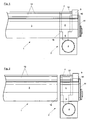
- Fig. 1 shows a side view of a paint chamber doctor blade 1 according to the invention, in which an end piece 2 is fixed to the chamber doctor blade body 3.
- the tail can be screwed by means not shown screws which run in the axial direction of the chambered doctor blade body 3, to this.
- FIG. 2 shows the same view as the FIG. 1 , However, the tail has now been removed from the chambered doctor blade body 3.
- the end piece 2 comprises an outlet opening 4, which via a cavity 23 (see Fig. 3 ) is connected to the trench-like recess 5, so that printing ink, which passes into this recess 5 can be removed via the outlet opening 4.
- the outlet opening 4 is concentrically surrounded by a dashed circle, which is intended to indicate that the outlet opening is provided with an internal thread. This can be screwed into the outlet opening a connector, which can be connected to a hose or pipe for the discharge of ink.
- the hose can be coupled to the connector, for example via a coupling.
- the recess 5 is connected to the interior 6 of the tail.
- This secondary space 6 is essentially limited by at least one wall 7, which, when the end piece 2 is screwed to the chambered doctor blade body 3, the auxiliary space 6 of the end piece 2 of the trough-like main space 8 of the chambered doctor blade body 3 (see FIG. 3 ) delimits.
- this wall 7 is shown in dashed lines. The effect of such walls is in the aforementioned patent DE 195 16 223 C2 the Applicant described in detail why more detailed explanations will be omitted here at this point.
- the wall 7 may be suitably removably attached to the end piece 2.
- this is Screw connections conceivable.
- the sealing body 9 is held in the circumferential direction of the ink transfer rollers, not shown, between two webs 10 of the end piece 2. In order to prevent an axial displacement of the seal body 9, this is the end face of the tail 2 held by a holding plate 11 which may be bolted to the end piece 2. However, preference is given to a pivotable retaining plate 11, whose execution and function in the patent EP 0 896 877 B1 the applicant is under protection. While the holding plate 11 according to the cited patent is pivotally mounted on the chambered doctor blade body 3, this holding plate 11 according to the present invention is also arranged on the end piece 2 which can be removed from the chambered doctoring body 3.
- a counter-holding wall 12 is provided, to which the sealing body can be applied.
- This counter-holding wall 12 like the wall 7, can be removably arranged on the end piece 2.
- the counter-holding wall 12 is formed integrally with the end piece 12.
- the doctor blades are placed on the support surfaces 13 of the chambered doctor blade body 3 and fixed there in a suitable manner.
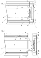
- the connecting seam 18 between end piece 2 and chamber doctor blade body 3 crosses this bearing surface (as in the Figures 1 and 2 is shown) and thus leads to leaks, it is according to the FIGS. 3 and 4 provided to form the bearing surfaces 13 extended relative to the chambered doctor blade body by means of extension sections 14, so that they extend to the sealing body 9.
- the webs 10 may have corresponding recesses 15. Between recess 15 and extension portion 14 of the support surface 13 sealing means can be provided.
- the doctor blades are fixed by means not described in more detail on the support surfaces 13.
- These fastening means comprise clamping rails, with which the doctor blades are pressed onto the support surfaces 13 and waves, which are inserted into the longitudinal recesses 16.
- the clamping rails may also include longitudinal webs which can grip the recesses 16. Regardless of how the fastening means are designed, it is provided that the depressions 16 continue as depressions 17 in the end piece. In general, it is advantageous if the cross-sectional contour of chamber doctor blade body 3 and end piece 2 is substantially congruent.
- FIG. 6 shown view of said embodiment in the region of the trench-like recess 5 is provided with a recess 24 which may be rectangular in shape.
- a seal 20 may be provided, which may be inserted into a groove around the trench-like depression 5 around the end piece 2 and the chambered doctor blade body 3 sufficiently seals against the end piece 2.
- This seal 20 is in the FIG. 6 shown in dashed lines and can continue below the seal body 9. In the FIG. 5 the seal 20 is shown as a dashed line.
- the end piece 2 may be provided with an extension piece 21 in a Farbschrakel 1 according to the invention, so that the end piece 2 is formed in the side view as an angle.
- This expression of the tail is not on the embodiment in the FIGS. 5 and 6 limited.
- This end piece makes it possible to attach the end piece to the underside of the chambered doctor blade body 3 with suitable fastening means, for example one or more of the screw 22 shown.
- This type of attachment of the tail is advantageous in many printing machines, since in the longitudinal direction of the ink chamber doctor blade is often not sufficient mounting space.
- FIG. 7 shows the embodiment according to FIG. 6 Clearly recognizable now is the appearance of the end of the ink chamber blade 1. Above all, now the recess 24 can be seen, which is introduced so that when deferred end piece 2, the trench-like depression 5 is exposed. As has already been explained with reference to the exemplary embodiments of the invention already described above, the trench-like depression 5 is in communication with the outlet opening 4, so that ink can flow out through the trench-like depression 5, the connection and the outlet opening.
- Farbschzigrakel 1 is pushed (see also FIG. 5 ).
- through holes 26 are arranged through which screws 22 can reach through to secure the end piece 2 to the paint chamber doctor blade.
- On the right side of the projection 21 is an elevation 25, in which the recess 5 and also the groove, in which the seal 20 is inserted, are introduced.
- the seal 20 is shown as a line which is partly solid and partly interrupted.
- the part shown as a broken line is covered by the seal 9.
- the part shown as a solid line is covered with deferred end piece 2 by the edges of the trough-like main chamber of the chambered doctor blade body and therefore in the illustration of FIG. 7 not covered and thus visible.
- FIG. 1 Each of the figures shows one end of a paint chamber doctor blade 1. It is understood that both ends of a ink chamber doctor blade 1 can be provided with the end pieces 2 described.
Landscapes
- Inking, Control Or Cleaning Of Printing Machines (AREA)
- Ink Jet (AREA)
- Application Of Or Painting With Fluid Materials (AREA)
- Crushing And Grinding (AREA)
Claims (12)
- Compartiment à encre (1) pour un mécanisme d'encrage d'une presse rotative, qui comporte au moins les éléments suivants:- un rouleau de transfert d'encre qui, à l'état de fonctionnement, tourne autour d'un axe,- un corps de chambre de racle oblong (3), s'étendant dans la direction de cet axe, qui comporte un évidement en forme de rainure,- deux lames de racle pouvant être fixées au corps de chambre de racle et pouvant être appliquées au rouleau de transfert d'encre,- deux corps d'étanchéité (9) qui sont disposés dans les zones d'extrémité du corps de chambre de racle et qui peuvent être appliqués, par leurs faces d'étanchéité, au rouleau de transfert d'encre,- une amenée d'encre par laquelle l'encre d'impression peut être acheminée à l'évidement en forme de rainure,- deux écoulements d'encre, par lesquels l'encre d'impression peut être évacuée de l'évidement en forme de rainure, où à chaque fois un écoulement d'encre est disposé dans une zone d'extrémité de l'évidement en forme de rainure,où- deux pièces d'extrémité (2) sont prévues, dans lesquelles se prolonge l'évidement en forme de rainure,- les écoulements d'encre sont disposés dans les pièces d'extrémité et- les pièces d'extrémité peuvent être fixées amoviblement aux zones d'extrémité du corps de chambre de racle,caractérisé
en ce qu'il est disposé à ou dans chaque pièce d'extrémité au moins une paroi intermédiaire (7) qui sépare l'évidement en forme de rainure en une chambre principale (8) et une chambre secondaire (6). - Compartiment à encre selon la revendication 1, caractérisé en ce que les corps d'étanchéité sont disposés aux ou dans les pièces d'extrémité.
- Compartiment à encre selon l'une des revendications précédentes, caractérisé en ce que les pièces d'extrémité sont réalisées en une forme angulaire, et est reliée au côté éloigné du rouleau de transfert d'encre du corps de chambre de racle à celui-ci.
- Compartiment à encre selon l'une des revendications précédentes, caractérisé en ce que les pièces d'extrémité sont réalisées essentiellement en matériau synthétique, de préférence en polypropylène.
- Compartiment à encre selon l'une des revendications précédentes, caractérisé en ce que les pièces d'extrémité peuvent être fabriquées au moyen d'un procédé de moulage par injection.
- Compartiment à encre selon l'une des revendications précédentes, caractérisé en ce qu'au moins une des pièces d'extrémité est pourvue d'au moins un connecteur d'un système de couplage de tuyaux.
- Compartiment à encre selon la revendication précédente, caractérisé en ce que la pièce d'extrémité et le connecteur sont réalisés en une pièce.
- Procédé de fabrication d'une racle de compartiment à encre pour un mécanisme d'encrage d'une presse rotative, qui comprend au moins les caractéristiques suivantes:- mise à disposition d'un corps de compartiment à encre oblong (1) qui comporte un évidement en forme de rainure,- mise à disposition de deux lames de racle pouvant être fixées au corps de compartiment à encre et pouvant être appliquées à un rouleau de transfert d'encre,- agencement de deux corps d'étanchéité (9) dans les zones d'extrémité du corps de compartiment à encre, qui peuvent être appliqués avec leurs faces d'étanchéité au rouleau de transfert d'encre,- réalisation d'une amenée d'encre par laquelle l'encre est amenée à l'évidement en forme de rainure,- réalisation de deux écoulements d'encre par lesquels l'encre est évacuée de l'évidement en forme de rainure, où à chaque fois un écoulement d'encre est disposé dans une zone d'extrémité de l'évidement en forme de rainure,où
au moins à chaque fois un écoulement d'encre est ménagé dans respectivement une pièce d'extrémité, où les pièces d'extrémité sont fixées amoviblement aux zones d'extrémité du corps de compartiment à encre,
caractérisé en ce qu'il est disposé à ou dans chaque pièce d'extrémité au moins une paroi intermédiaire (7) qui sépare l'évidement en forme de rainure en une chambre principale (8) et une chambre secondaire (6). - Procédé selon la revendication précédente, caractérisé en ce que les pièces d'extrémité sont fabriquées en matériau synthétique.
- Procédé selon l'une des deux revendications précédentes, caractérisé en ce que les pièces d'extrémité sont moulées par injection.
- Procédé selon la revendication précédente, caractérisé en ce que les pièces d'extrémité sont munies de connecteurs d'un système de couplage de tuyaux.
- Procédé selon la revendication précédente, caractérisé en ce qu'une pièce d'extrémité et le connecteur sont réalisés en une pièce.
Applications Claiming Priority (2)
| Application Number | Priority Date | Filing Date | Title |
|---|---|---|---|
| DE102007027385A DE102007027385B4 (de) | 2007-06-11 | 2007-06-11 | Farbkammer für ein Farbwerk einer Rotationsdruckmaschine und Verfahren zur Herstellung einer solchen Farbkammer |
| PCT/EP2008/057262 WO2008152049A1 (fr) | 2007-06-11 | 2008-06-11 | Compartiment à encre de mécanisme d'encrage de presse rotative et procédé pour produire un compartiment à encre de ce type |
Publications (2)
| Publication Number | Publication Date |
|---|---|
| EP2158085A1 EP2158085A1 (fr) | 2010-03-03 |
| EP2158085B1 true EP2158085B1 (fr) | 2010-08-18 |
Family
ID=39743101
Family Applications (1)
| Application Number | Title | Priority Date | Filing Date |
|---|---|---|---|
| EP08774063A Not-in-force EP2158085B1 (fr) | 2007-06-11 | 2008-06-11 | Compartiment à encre de mécanisme d'encrage de presse rotative et procédé pour produire un compartiment à encre de ce type |
Country Status (5)
| Country | Link |
|---|---|
| EP (1) | EP2158085B1 (fr) |
| AT (1) | ATE477929T1 (fr) |
| DE (2) | DE102007027385B4 (fr) |
| ES (1) | ES2350813T3 (fr) |
| WO (1) | WO2008152049A1 (fr) |
Families Citing this family (2)
| Publication number | Priority date | Publication date | Assignee | Title |
|---|---|---|---|---|
| DE202009013643U1 (de) | 2009-10-26 | 2011-03-17 | Zeljko, Kitic | Dichtelement |
| DE102018129093A1 (de) * | 2018-11-19 | 2020-05-20 | Windmöller & Hölscher Kg | Drainbox für eine Rakelkammer |
Family Cites Families (10)
| Publication number | Priority date | Publication date | Assignee | Title |
|---|---|---|---|---|
| US4821672A (en) * | 1987-06-22 | 1989-04-18 | Nick Bruno | Doctor blade assembly with rotary end seals and interchangeable heads |
| US5085144A (en) * | 1990-05-03 | 1992-02-04 | Motter Printing Press Co. | Ink fountain apparatus |
| SE470283B (sv) * | 1992-05-22 | 1994-01-10 | Aake Boeoese | Kammarrakelanordning för tryckverk och tryckverk |
| US5410961A (en) * | 1992-12-30 | 1995-05-02 | Fit Group, Inc. | Fountain assembly |
| DE4401365A1 (de) * | 1994-01-18 | 1995-07-20 | Roland Man Druckmasch | Vorrichtung zur Einfärbung einer Rasterwalze |
| DE19516223C2 (de) | 1995-05-03 | 1997-03-20 | Windmoeller & Hoelscher | Rakelvorrichtung für ein Spülfarbwerk einer Rotationsdruckmaschine |
| DE19734910A1 (de) | 1997-08-12 | 1999-02-18 | Windmoeller & Hoelscher | Rakelvorrichtung für ein Spülfarbwerk einer Rotationsdruckmaschine |
| DE10150488B4 (de) | 2001-10-16 | 2005-08-04 | Windmöller & Hölscher Kg | Stirnseitige Abdichtung der Rakelkammer |
| JP2005088586A (ja) * | 2003-09-12 | 2005-04-07 | Metronic Ag | インキ壺 |
| SE527080C2 (sv) * | 2004-05-05 | 2005-12-20 | Akeboose Internat Ab | Anordning och förfarande för kammarrakel |
-
2007
- 2007-06-11 DE DE102007027385A patent/DE102007027385B4/de not_active Expired - Fee Related
-
2008
- 2008-06-11 AT AT08774063T patent/ATE477929T1/de active
- 2008-06-11 EP EP08774063A patent/EP2158085B1/fr not_active Not-in-force
- 2008-06-11 DE DE502008001177T patent/DE502008001177D1/de active Active
- 2008-06-11 ES ES08774063T patent/ES2350813T3/es active Active
- 2008-06-11 WO PCT/EP2008/057262 patent/WO2008152049A1/fr not_active Ceased
Also Published As
| Publication number | Publication date |
|---|---|
| DE502008001177D1 (de) | 2010-09-30 |
| ATE477929T1 (de) | 2010-09-15 |
| WO2008152049A1 (fr) | 2008-12-18 |
| EP2158085A1 (fr) | 2010-03-03 |
| DE102007027385B4 (de) | 2011-06-16 |
| DE102007027385A1 (de) | 2009-02-12 |
| ES2350813T3 (es) | 2011-01-27 |
Similar Documents
| Publication | Publication Date | Title |
|---|---|---|
| DE4138807C1 (en) | Colour chamber doctor - is for colour-transfer, screened circular cylindrical body such as screen roller or engraved cylinder | |
| EP0270816B1 (fr) | Tête d'extrusion | |
| EP1302315B1 (fr) | Joint d'étanchéité d'une chambre de racle | |
| DE9215854U1 (de) | Einrichtung zum Beschichten laufender Materialbahnen, insbesondere Farbkammerrakel für einen farbübertragenden, gerasterten kreiszylindrischen Körper, wie eine Rasterwalze oder einen gravierten Zylinder | |
| DE102019105227B4 (de) | Schaber mit Wasserschmierung | |
| DE3427022C2 (fr) | ||
| EP0765749B1 (fr) | Dispositif de raclage pour l'encrier à circulation d'encre d'une presse à imprimer rotative | |
| EP1103377B1 (fr) | Dispositif d'étanchéification d'une alimentation en encre dans des machines d'impression | |
| EP2234786B1 (fr) | Unité d'injection à piston pour machine de moulage par injection | |
| AT413270B (de) | Haltevorrichtung für eine extrusionsdüse | |
| DE102007027385B4 (de) | Farbkammer für ein Farbwerk einer Rotationsdruckmaschine und Verfahren zur Herstellung einer solchen Farbkammer | |
| DE4012618C2 (fr) | ||
| CH695262A5 (de) | Kammerrakel. | |
| WO2008152022A1 (fr) | Racle de compartiment à encre dans un mécanisme d'encrage de presse rotative et procédé pour produire une racle de compartiment à encre | |
| EP1090756B1 (fr) | Chambre à râcles | |
| EP2158084B1 (fr) | Racle de compartiment à encre dans un mécanisme d'encrage de presse rotative | |
| EP1815983B1 (fr) | Presse | |
| EP3758939A1 (fr) | Sécheur | |
| DE102016108256A1 (de) | Nachrüstungsset, Lauffähigkeitskomponente und Verfahren zum Modifizieren eines Saugkastens | |
| EP1859938A2 (fr) | Dispositif destiné au nettoyage d'un cylindre d'une presse | |
| DE2916133A1 (de) | Kunststoffspritzgussmaschine | |
| EP2995452A1 (fr) | Machine d'impression à tampon rotatif | |
| EP2049337B1 (fr) | Dispositif de nettoyage de surfaces de cylindres d'impression | |
| EP3124245A1 (fr) | Dispositif de vidange de la conduite d'acheminement et d'evacuation d'un cylindre d'encrage d'une imprimante | |
| DE102008042741B4 (de) | Reinigungsvorrichtung für einen Zylinder oder eine Walze einer Druckmaschine |
Legal Events
| Date | Code | Title | Description |
|---|---|---|---|
| PUAI | Public reference made under article 153(3) epc to a published international application that has entered the european phase |
Free format text: ORIGINAL CODE: 0009012 |
|
| 17P | Request for examination filed |
Effective date: 20100111 |
|
| AK | Designated contracting states |
Kind code of ref document: A1 Designated state(s): AT BE BG CH CY CZ DE DK EE ES FI FR GB GR HR HU IE IS IT LI LT LU LV MC MT NL NO PL PT RO SE SI SK TR |
|
| AX | Request for extension of the european patent |
Extension state: AL BA MK RS |
|
| GRAP | Despatch of communication of intention to grant a patent |
Free format text: ORIGINAL CODE: EPIDOSNIGR1 |
|
| GRAS | Grant fee paid |
Free format text: ORIGINAL CODE: EPIDOSNIGR3 |
|
| GRAA | (expected) grant |
Free format text: ORIGINAL CODE: 0009210 |
|
| AK | Designated contracting states |
Kind code of ref document: B1 Designated state(s): AT BE BG CH CY CZ DE DK EE ES FI FR GB GR HR HU IE IS IT LI LT LU LV MC MT NL NO PL PT RO SE SI SK TR |
|
| REG | Reference to a national code |
Ref country code: GB Ref legal event code: FG4D Free format text: NOT ENGLISH |
|
| REG | Reference to a national code |
Ref country code: CH Ref legal event code: NV Representative=s name: BOVARD AG PATENTANWAELTE Ref country code: CH Ref legal event code: EP |
|
| REG | Reference to a national code |
Ref country code: IE Ref legal event code: FG4D Free format text: LANGUAGE OF EP DOCUMENT: GERMAN |
|
| REF | Corresponds to: |
Ref document number: 502008001177 Country of ref document: DE Date of ref document: 20100930 Kind code of ref document: P |
|
| REG | Reference to a national code |
Ref country code: NL Ref legal event code: VDEP Effective date: 20100818 |
|
| LTIE | Lt: invalidation of european patent or patent extension |
Effective date: 20100818 |
|
| REG | Reference to a national code |
Ref country code: ES Ref legal event code: FG2A Effective date: 20110117 |
|
| PG25 | Lapsed in a contracting state [announced via postgrant information from national office to epo] |
Ref country code: NO Free format text: LAPSE BECAUSE OF FAILURE TO SUBMIT A TRANSLATION OF THE DESCRIPTION OR TO PAY THE FEE WITHIN THE PRESCRIBED TIME-LIMIT Effective date: 20101118 Ref country code: FI Free format text: LAPSE BECAUSE OF FAILURE TO SUBMIT A TRANSLATION OF THE DESCRIPTION OR TO PAY THE FEE WITHIN THE PRESCRIBED TIME-LIMIT Effective date: 20100818 Ref country code: LT Free format text: LAPSE BECAUSE OF FAILURE TO SUBMIT A TRANSLATION OF THE DESCRIPTION OR TO PAY THE FEE WITHIN THE PRESCRIBED TIME-LIMIT Effective date: 20100818 |
|
| PG25 | Lapsed in a contracting state [announced via postgrant information from national office to epo] |
Ref country code: PL Free format text: LAPSE BECAUSE OF FAILURE TO SUBMIT A TRANSLATION OF THE DESCRIPTION OR TO PAY THE FEE WITHIN THE PRESCRIBED TIME-LIMIT Effective date: 20100818 Ref country code: HR Free format text: LAPSE BECAUSE OF FAILURE TO SUBMIT A TRANSLATION OF THE DESCRIPTION OR TO PAY THE FEE WITHIN THE PRESCRIBED TIME-LIMIT Effective date: 20100818 Ref country code: SI Free format text: LAPSE BECAUSE OF FAILURE TO SUBMIT A TRANSLATION OF THE DESCRIPTION OR TO PAY THE FEE WITHIN THE PRESCRIBED TIME-LIMIT Effective date: 20100818 Ref country code: IS Free format text: LAPSE BECAUSE OF FAILURE TO SUBMIT A TRANSLATION OF THE DESCRIPTION OR TO PAY THE FEE WITHIN THE PRESCRIBED TIME-LIMIT Effective date: 20101218 Ref country code: BG Free format text: LAPSE BECAUSE OF FAILURE TO SUBMIT A TRANSLATION OF THE DESCRIPTION OR TO PAY THE FEE WITHIN THE PRESCRIBED TIME-LIMIT Effective date: 20101118 Ref country code: CY Free format text: LAPSE BECAUSE OF FAILURE TO SUBMIT A TRANSLATION OF THE DESCRIPTION OR TO PAY THE FEE WITHIN THE PRESCRIBED TIME-LIMIT Effective date: 20100818 |
|
| REG | Reference to a national code |
Ref country code: IE Ref legal event code: FD4D |
|
| PG25 | Lapsed in a contracting state [announced via postgrant information from national office to epo] |
Ref country code: GR Free format text: LAPSE BECAUSE OF FAILURE TO SUBMIT A TRANSLATION OF THE DESCRIPTION OR TO PAY THE FEE WITHIN THE PRESCRIBED TIME-LIMIT Effective date: 20101119 Ref country code: LV Free format text: LAPSE BECAUSE OF FAILURE TO SUBMIT A TRANSLATION OF THE DESCRIPTION OR TO PAY THE FEE WITHIN THE PRESCRIBED TIME-LIMIT Effective date: 20100818 Ref country code: NL Free format text: LAPSE BECAUSE OF FAILURE TO SUBMIT A TRANSLATION OF THE DESCRIPTION OR TO PAY THE FEE WITHIN THE PRESCRIBED TIME-LIMIT Effective date: 20100818 Ref country code: SE Free format text: LAPSE BECAUSE OF FAILURE TO SUBMIT A TRANSLATION OF THE DESCRIPTION OR TO PAY THE FEE WITHIN THE PRESCRIBED TIME-LIMIT Effective date: 20100818 |
|
| REG | Reference to a national code |
Ref country code: CH Ref legal event code: PFA Owner name: WINDMOELLER & HOELSCHER KG Free format text: WINDMOELLER & HOELSCHER KG#MUENSTERSTRASSE 50#49525 LENGERICH (DE) -TRANSFER TO- WINDMOELLER & HOELSCHER KG#MUENSTERSTRASSE 50#49525 LENGERICH (DE) |
|
| PG25 | Lapsed in a contracting state [announced via postgrant information from national office to epo] |
Ref country code: IE Free format text: LAPSE BECAUSE OF FAILURE TO SUBMIT A TRANSLATION OF THE DESCRIPTION OR TO PAY THE FEE WITHIN THE PRESCRIBED TIME-LIMIT Effective date: 20100818 Ref country code: DK Free format text: LAPSE BECAUSE OF FAILURE TO SUBMIT A TRANSLATION OF THE DESCRIPTION OR TO PAY THE FEE WITHIN THE PRESCRIBED TIME-LIMIT Effective date: 20100818 |
|
| PG25 | Lapsed in a contracting state [announced via postgrant information from national office to epo] |
Ref country code: SK Free format text: LAPSE BECAUSE OF FAILURE TO SUBMIT A TRANSLATION OF THE DESCRIPTION OR TO PAY THE FEE WITHIN THE PRESCRIBED TIME-LIMIT Effective date: 20100818 Ref country code: CZ Free format text: LAPSE BECAUSE OF FAILURE TO SUBMIT A TRANSLATION OF THE DESCRIPTION OR TO PAY THE FEE WITHIN THE PRESCRIBED TIME-LIMIT Effective date: 20100818 Ref country code: RO Free format text: LAPSE BECAUSE OF FAILURE TO SUBMIT A TRANSLATION OF THE DESCRIPTION OR TO PAY THE FEE WITHIN THE PRESCRIBED TIME-LIMIT Effective date: 20100818 Ref country code: EE Free format text: LAPSE BECAUSE OF FAILURE TO SUBMIT A TRANSLATION OF THE DESCRIPTION OR TO PAY THE FEE WITHIN THE PRESCRIBED TIME-LIMIT Effective date: 20100818 |
|
| PLBE | No opposition filed within time limit |
Free format text: ORIGINAL CODE: 0009261 |
|
| STAA | Information on the status of an ep patent application or granted ep patent |
Free format text: STATUS: NO OPPOSITION FILED WITHIN TIME LIMIT |
|
| 26N | No opposition filed |
Effective date: 20110519 |
|
| REG | Reference to a national code |
Ref country code: DE Ref legal event code: R097 Ref document number: 502008001177 Country of ref document: DE Effective date: 20110519 |
|
| PG25 | Lapsed in a contracting state [announced via postgrant information from national office to epo] |
Ref country code: MT Free format text: LAPSE BECAUSE OF FAILURE TO SUBMIT A TRANSLATION OF THE DESCRIPTION OR TO PAY THE FEE WITHIN THE PRESCRIBED TIME-LIMIT Effective date: 20100818 |
|
| BERE | Be: lapsed |
Owner name: WINDMOLLER & HOLSCHER K.G. Effective date: 20110630 |
|
| REG | Reference to a national code |
Ref country code: FR Ref legal event code: ST Effective date: 20120229 |
|
| PG25 | Lapsed in a contracting state [announced via postgrant information from national office to epo] |
Ref country code: BE Free format text: LAPSE BECAUSE OF NON-PAYMENT OF DUE FEES Effective date: 20110630 |
|
| PG25 | Lapsed in a contracting state [announced via postgrant information from national office to epo] |
Ref country code: FR Free format text: LAPSE BECAUSE OF NON-PAYMENT OF DUE FEES Effective date: 20110630 |
|
| GBPC | Gb: european patent ceased through non-payment of renewal fee |
Effective date: 20120611 |
|
| PG25 | Lapsed in a contracting state [announced via postgrant information from national office to epo] |
Ref country code: MC Free format text: LAPSE BECAUSE OF NON-PAYMENT OF DUE FEES Effective date: 20110630 Ref country code: GB Free format text: LAPSE BECAUSE OF NON-PAYMENT OF DUE FEES Effective date: 20120611 |
|
| PG25 | Lapsed in a contracting state [announced via postgrant information from national office to epo] |
Ref country code: LU Free format text: LAPSE BECAUSE OF NON-PAYMENT OF DUE FEES Effective date: 20110611 |
|
| PG25 | Lapsed in a contracting state [announced via postgrant information from national office to epo] |
Ref country code: PT Free format text: LAPSE BECAUSE OF NON-PAYMENT OF DUE FEES Effective date: 20100818 |
|
| PG25 | Lapsed in a contracting state [announced via postgrant information from national office to epo] |
Ref country code: TR Free format text: LAPSE BECAUSE OF FAILURE TO SUBMIT A TRANSLATION OF THE DESCRIPTION OR TO PAY THE FEE WITHIN THE PRESCRIBED TIME-LIMIT Effective date: 20100818 |
|
| PG25 | Lapsed in a contracting state [announced via postgrant information from national office to epo] |
Ref country code: HU Free format text: LAPSE BECAUSE OF FAILURE TO SUBMIT A TRANSLATION OF THE DESCRIPTION OR TO PAY THE FEE WITHIN THE PRESCRIBED TIME-LIMIT Effective date: 20100818 |
|
| REG | Reference to a national code |
Ref country code: AT Ref legal event code: MM01 Ref document number: 477929 Country of ref document: AT Kind code of ref document: T Effective date: 20130611 |
|
| PG25 | Lapsed in a contracting state [announced via postgrant information from national office to epo] |
Ref country code: AT Free format text: LAPSE BECAUSE OF NON-PAYMENT OF DUE FEES Effective date: 20130611 |
|
| PGFP | Annual fee paid to national office [announced via postgrant information from national office to epo] |
Ref country code: IT Payment date: 20190624 Year of fee payment: 12 |
|
| PGFP | Annual fee paid to national office [announced via postgrant information from national office to epo] |
Ref country code: ES Payment date: 20190725 Year of fee payment: 12 Ref country code: DE Payment date: 20190630 Year of fee payment: 12 |
|
| PGFP | Annual fee paid to national office [announced via postgrant information from national office to epo] |
Ref country code: CH Payment date: 20200626 Year of fee payment: 13 |
|
| REG | Reference to a national code |
Ref country code: DE Ref legal event code: R119 Ref document number: 502008001177 Country of ref document: DE |
|
| PG25 | Lapsed in a contracting state [announced via postgrant information from national office to epo] |
Ref country code: DE Free format text: LAPSE BECAUSE OF NON-PAYMENT OF DUE FEES Effective date: 20210101 |
|
| PG25 | Lapsed in a contracting state [announced via postgrant information from national office to epo] |
Ref country code: IT Free format text: LAPSE BECAUSE OF NON-PAYMENT OF DUE FEES Effective date: 20200611 |
|
| REG | Reference to a national code |
Ref country code: ES Ref legal event code: FD2A Effective date: 20211103 |
|
| PG25 | Lapsed in a contracting state [announced via postgrant information from national office to epo] |
Ref country code: ES Free format text: LAPSE BECAUSE OF NON-PAYMENT OF DUE FEES Effective date: 20200612 |
|
| REG | Reference to a national code |
Ref country code: CH Ref legal event code: PL |
|
| PG25 | Lapsed in a contracting state [announced via postgrant information from national office to epo] |
Ref country code: LI Free format text: LAPSE BECAUSE OF NON-PAYMENT OF DUE FEES Effective date: 20210630 Ref country code: CH Free format text: LAPSE BECAUSE OF NON-PAYMENT OF DUE FEES Effective date: 20210630 |