EP2158665B1 - Apparatus and method for winding and inserting coils in cores of dynamoelectric machines - Google Patents
Apparatus and method for winding and inserting coils in cores of dynamoelectric machines Download PDFInfo
- Publication number
- EP2158665B1 EP2158665B1 EP08762921.8A EP08762921A EP2158665B1 EP 2158665 B1 EP2158665 B1 EP 2158665B1 EP 08762921 A EP08762921 A EP 08762921A EP 2158665 B1 EP2158665 B1 EP 2158665B1
- Authority
- EP
- European Patent Office
- Prior art keywords
- translating
- winding
- winding form
- expulsion
- coils
- Prior art date
- Legal status (The legal status is an assumption and is not a legal conclusion. Google has not performed a legal analysis and makes no representation as to the accuracy of the status listed.)
- Active
Links
Images



Classifications
-
- H—ELECTRICITY
- H02—GENERATION; CONVERSION OR DISTRIBUTION OF ELECTRIC POWER
- H02K—DYNAMO-ELECTRIC MACHINES
- H02K15/00—Processes or apparatus specially adapted for manufacturing, assembling, maintaining or repairing of dynamo-electric machines
- H02K15/04—Processes or apparatus specially adapted for manufacturing, assembling, maintaining or repairing of dynamo-electric machines of windings prior to their mounting into the machines
-
- H—ELECTRICITY
- H02—GENERATION; CONVERSION OR DISTRIBUTION OF ELECTRIC POWER
- H02K—DYNAMO-ELECTRIC MACHINES
- H02K15/00—Processes or apparatus specially adapted for manufacturing, assembling, maintaining or repairing of dynamo-electric machines
- H02K15/06—Embedding prefabricated windings in the machines
- H02K15/062—Windings in slots; Salient pole windings
- H02K15/065—Windings consisting of complete sections, e.g. coils or waves
-
- H—ELECTRICITY
- H02—GENERATION; CONVERSION OR DISTRIBUTION OF ELECTRIC POWER
- H02K—DYNAMO-ELECTRIC MACHINES
- H02K15/00—Processes or apparatus specially adapted for manufacturing, assembling, maintaining or repairing of dynamo-electric machines
- H02K15/04—Processes or apparatus specially adapted for manufacturing, assembling, maintaining or repairing of dynamo-electric machines of windings prior to their mounting into the machines
- H02K15/043—Processes or apparatus specially adapted for manufacturing, assembling, maintaining or repairing of dynamo-electric machines of windings prior to their mounting into the machines winding flat conductive wires or sheets
- H02K15/0431—Concentrated windings
Definitions
- Formation of a lead extending from the coils occurs by moving a wire dispenser and a wire gripping unit from which extra wire is extracted to form the lead. More particularly, during the movements of the unit, tension is applied on the extra wire to pull it from the dispenser. At the same time, the expulsion member is maintained on the insertion tool at the level of the coil from which the extra wire departs, thereby impeding that wire can be pulled away from the coil.
- Rotation member 35 is assembled on bearings 36 and 37, which are seated in a cylindrical frame portion 38, and results centered on axis A.
- Portion 38 can be a stationary portion belonging to the frame 40 of the apparatus.
- Frame 40 can be supported on the floor of the facility where the apparatus of the invention is installed.
- Rotation member 35 is rotated around axis A by means of belt 39.
- Belt 39 is driven by a motor (not shown), which can be supported by frame 40.
- Bars 33 and 34 are also respectively assembled in bushes 43 and 44 (shown externally and not in section) carried by general support member 15.
- Bushes 43 and 44 allow bars 33 and 34 to translate parallel to axis A and backwards and forwards with respect to general support member 15.
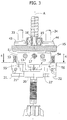
- the engagement of bars 33 and 34 with bushes 43 and 44 imparts the rotation of member 35 to general support member 15, which in turn rotates form members 10' and 10" around axis A for winding and other operations that draw a wire or plural wires from a wire dispenser 61 (shown in figure 5 ).
- the start end S of a wire or of plural wires to be drawn can be connected to clamp 45 positioned between form members 10' and 10" (see Fig. 2 ).
- expulsion member 20 can be translated backwards and forwards parallel to axis A by means of bars 33 and 34.
- Bars 33 and 34 can be translated backwards and forwards parallel to axis A by means of collar 32.
- Collar 32 can be translated backwards and forwards parallel to axis A, together with sleeve 31, which can be translated backwards and forwards parallel to axis A by rotating tube 18 with motor 30.
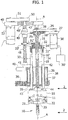
- General frame member 27 can be translated backwards and forwards parallel to axis A (see Fig. 1 ) for translating form members 10' and 10" backwards and forwards parallel to axis A.
- the translation of general frame member 27 backwards and forwards parallel to axis A occurs on upstanding guide bars like 47 fixed to frame 40.
- the translation movement of general frame member 27 can be obtained by rotation of screw 48, which engages threaded sleeve 49. Threaded sleeve 49 is fixed to general frame member 27.
- Threaded screw 48 is mounted on bearings like 49' seated in frame 40 and has attached a pulley wheel 50.
- Belt 51 can turn pulley wheel 50, which in turn is rotated with motor 52 flanged to frame 40. In this way, rotation of motor 52 translates frame member 27 backwards and forwards parallel to axis A, which in turn translates form members 10' and 10" backwards and forwards parallel to axis A due to the translation of tube 18.
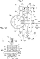
- bars 33 and 34 When requiring to adjust the position of expulsion member 20 to suit the adjustment of form members 10' and 10", bars 33 and 34 can be moved in direction A1 (see Figs. 2 , 3 , 4 and 4a ) to bring the top portions of pins 53 and 54 in abutment with the underside of member 15. Further movement of bars 33 and 34 in direction A1, after abutment of the top portions of pins 53 and 54 causes actuating pins 53 and 54 to release the lock mechanisms that are present inside members 24 and 25 to maintain shafts 23 and 24 temporary locked.
- Fig. 4a shows the lock mechanism actuated by pin 53.
- actuating pin 53 is screwed onto to pin 70, which can slide on bushes 71 present inside members 24.
- the lower end 70' of pin has a conical shape for engaging plate members 72 and 73, which are hinged in seat 74 by means of pins 75 and 76, respectively.
- Shaft 23 passes through apertures of plate members 72 and 73 and through aperture 77 of pin 70, as shown in Fig. 4a .
- Bars 33 and 34 for translating expulsion member 20 along the insertion tool are not limited in the extension of their movement by the position of form members 10' and 10", nor by the position of member 15 for supporting form members 10' and 10".
- the bars are able to pass through support member 15 without being obstructed by support member 15.
- the wire dispenser and gripping unit 60 which holds and delivers a wire or plural wires through dispenser 61 can move in synchronism with expulsion member 20 when transferring the coils to the transfer position 62 shown. This will guarantee that the wire extension CL going to dispenser 60 is maintained of a constant length and that portions of wires of coil C are not pulled out.
- wire extension CL needs to be clamped by clamp 45 present between the winding form members. This is achieved by forming a further length of the wire extension CL in order to make it reach the clamp through movement of gripping unit 60 which needs to become aligned with the clamp. The movements of gripping unit 60 to achieve the alignment create the further length of wire extension CL by pulling extra wire from dispenser 61.
- insertion tool 62 can also be indexed around its centre axis 66 or rotated around axis A to allow unit 60 to place the wire in the clamp, therefore an even further length of wire extension CL can be formed.
- expulsion member 20 remains at the transfer position 62 of the last coil C from which wire CL departs. In this way the underside of expulsion member 20 facing the coil acts as an engagement surface that impedes that extra wire is drawn from coil C.
- FIG. 6 which shows the winding form after a half turn rotation around axis A for the winding operation and with an initial lead CL1 extending from the clamp of the winding form.
- the initial lead CL1 is undesirably deformed towards area 80, where wire or plural wires will be drawn on the winding form.
- the deformed portion of the lead CL1 can interfere with wire that is successively dispensed on surface 12"' to form the coils.
- a portion 81' of cross bar 81 which is fixed to expulsion member 20 (see figure 4 ) can be brought into alignment (see the position of portion S1' in Fig. 6 ) with the deformed portion of the lead CL1 by movement of the expulsion member through a selected number of rotations of motor 30.
- further movement of the cross bar in direction A2 can deform initial lead CL1 to the position CL1'; in this manner away from area SO so as to avoid the interference with the wire or plural wires that need to be wound on surface 12"'.
- the apparatus of the invention makes it possible to transfer coils from the winding form to the insertion tool without risk of losing the correct stratification condition of the wires produced on the winding form. This is achieved for the reason that it is possible to insert each coil without requiring to push it with another coil, due to there not being undesirable limits to the path of the expulsion member, also for the reason that the wire connection between a wound coil and a coil to be wound later can be formed without removing wire from the wound coil, and also for the reason that means are provided for realigning end portions of wire which are not correctly aligned.
Landscapes
- Engineering & Computer Science (AREA)
- Manufacturing & Machinery (AREA)
- Power Engineering (AREA)
- Manufacture Of Motors, Generators (AREA)
- Manufacturing Cores, Coils, And Magnets (AREA)
- Replacement Of Web Rolls (AREA)
- Basic Packing Technique (AREA)
Priority Applications (1)
| Application Number | Priority Date | Filing Date | Title |
|---|---|---|---|
| SI200831875T SI2158665T1 (sl) | 2007-06-18 | 2008-06-16 | Naprava in postopki za navijanje in vstavljanje tuljav v jedra dinamoelektričnih strojev |
Applications Claiming Priority (2)
| Application Number | Priority Date | Filing Date | Title |
|---|---|---|---|
| IT000436A ITTO20070436A1 (it) | 2007-06-18 | 2007-06-18 | "apparecchio e procedimento per avvolgere ed inserire bobine in nuclei di macchine dinamoelettriche" |
| PCT/IB2008/001600 WO2008155635A2 (en) | 2007-06-18 | 2008-06-16 | Apparatus and method for winding and inserting coils in cores of dynamoelectric machines |
Publications (2)
| Publication Number | Publication Date |
|---|---|
| EP2158665A2 EP2158665A2 (en) | 2010-03-03 |
| EP2158665B1 true EP2158665B1 (en) | 2017-08-30 |
Family
ID=40129073
Family Applications (1)
| Application Number | Title | Priority Date | Filing Date |
|---|---|---|---|
| EP08762921.8A Active EP2158665B1 (en) | 2007-06-18 | 2008-06-16 | Apparatus and method for winding and inserting coils in cores of dynamoelectric machines |
Country Status (8)
| Country | Link |
|---|---|
| EP (1) | EP2158665B1 (da) |
| KR (1) | KR101342264B1 (da) |
| CN (1) | CN101755378B (da) |
| DK (1) | DK2158665T3 (da) |
| ES (1) | ES2649312T3 (da) |
| IT (1) | ITTO20070436A1 (da) |
| SI (1) | SI2158665T1 (da) |
| WO (1) | WO2008155635A2 (da) |
Families Citing this family (2)
| Publication number | Priority date | Publication date | Assignee | Title |
|---|---|---|---|---|
| JP5821606B2 (ja) * | 2011-12-19 | 2015-11-24 | アイシン精機株式会社 | 回転電機のステータの製造方法 |
| EP3958448B1 (en) * | 2019-04-16 | 2024-05-08 | Rainbow Robotics | Stator coil winding device |
Citations (2)
| Publication number | Priority date | Publication date | Assignee | Title |
|---|---|---|---|---|
| GB2135603A (en) * | 1982-09-30 | 1984-09-05 | Industra Products | Device for forming electrical coils and transferring the coils for subsequent insertion into a slotted magnetic core |
| US5232026A (en) * | 1991-07-19 | 1993-08-03 | Statomat Spezialmaschinen Gmbh | Method and apparatus for the winding of electric machine coils comprising parallel wires |
Family Cites Families (6)
| Publication number | Priority date | Publication date | Assignee | Title |
|---|---|---|---|---|
| CH374112A (de) * | 1959-06-18 | 1963-12-31 | Mez Mohelnice Np | Halbautomatische Wickelvorrichtung für die Träufelwicklung von Statorspulen von Asynchronmotoren |
| JPS61254049A (ja) * | 1985-05-03 | 1986-11-11 | Nippon Denso Co Ltd | コイルの巻線装置 |
| JPH077897A (ja) * | 1993-06-21 | 1995-01-10 | Sony Corp | コイル形成用巻治具と巻線装置並びに巻線方法 |
| IT1295594B1 (it) * | 1997-06-23 | 1999-05-13 | Atop Spa | Apparecchiatura e metodo per l'azionamento ed il bilanciamento inerziale a corsa variabile di un albero avvolgifilo per una macchina |
| JPH11289723A (ja) * | 1998-04-03 | 1999-10-19 | Hitachi Ltd | 回転電機の固定子の製造装置及び製造方法 |
| JP2005102402A (ja) * | 2003-09-24 | 2005-04-14 | Aisin Aw Co Ltd | ステータ製造装置 |
-
2007
- 2007-06-18 IT IT000436A patent/ITTO20070436A1/it unknown
-
2008
- 2008-06-16 KR KR1020097026809A patent/KR101342264B1/ko active Active
- 2008-06-16 DK DK08762921.8T patent/DK2158665T3/da active
- 2008-06-16 CN CN2008800209927A patent/CN101755378B/zh active Active
- 2008-06-16 EP EP08762921.8A patent/EP2158665B1/en active Active
- 2008-06-16 WO PCT/IB2008/001600 patent/WO2008155635A2/en not_active Ceased
- 2008-06-16 ES ES08762921.8T patent/ES2649312T3/es active Active
- 2008-06-16 SI SI200831875T patent/SI2158665T1/sl unknown
Patent Citations (2)
| Publication number | Priority date | Publication date | Assignee | Title |
|---|---|---|---|---|
| GB2135603A (en) * | 1982-09-30 | 1984-09-05 | Industra Products | Device for forming electrical coils and transferring the coils for subsequent insertion into a slotted magnetic core |
| US5232026A (en) * | 1991-07-19 | 1993-08-03 | Statomat Spezialmaschinen Gmbh | Method and apparatus for the winding of electric machine coils comprising parallel wires |
Also Published As
| Publication number | Publication date |
|---|---|
| ITTO20070436A1 (it) | 2008-12-19 |
| KR101342264B1 (ko) | 2014-01-10 |
| SI2158665T1 (sl) | 2017-11-30 |
| WO2008155635A2 (en) | 2008-12-24 |
| EP2158665A2 (en) | 2010-03-03 |
| ES2649312T3 (es) | 2018-01-11 |
| KR20100017901A (ko) | 2010-02-16 |
| CN101755378A (zh) | 2010-06-23 |
| CN101755378B (zh) | 2012-12-05 |
| DK2158665T3 (da) | 2017-11-13 |
| WO2008155635A3 (en) | 2009-02-19 |
Similar Documents
| Publication | Publication Date | Title |
|---|---|---|
| US10554106B2 (en) | Apparatus for winding and terminating dynamo electric machine cores | |
| KR101392465B1 (ko) | 다이나모 전기 기기의 코어의 코일 지지체 및 싱글 폴을 권취하는 장치 및 방법 | |
| US8726493B2 (en) | Clamping system of special conductors for a stator or rotor bar winding for an electric machine | |
| EP2260567B1 (en) | Apparatus and method for winding and terminating cores of dynamoelectric machines | |
| CN101401283B (zh) | 用于缠绕电动/发电机芯部的线圈的设备和方法 | |
| DK2583373T3 (da) | Anordning og fremgangsmåde til vikling af spolebærere og enkeltpoler af kerner til dynamoelektriske maskiner | |
| US8893374B2 (en) | Method for terminating leads of plural wires in dynamo electric machine core | |
| EP2158665B1 (en) | Apparatus and method for winding and inserting coils in cores of dynamoelectric machines | |
| EP2889990B1 (en) | Device for inserting, winding and layering a wire on one or more stator or rotor cores | |
| EP0490173B1 (en) | Stator winding machine | |
| US20210036588A1 (en) | Method and device for producing rotors and stators including the production of connection wires | |
| EP2144352B1 (en) | Apparatus and methods for inserting coils and cover wedges in the slots of dynamoelectric machine cores | |
| US7370401B2 (en) | Apparatus and methods for wire coil lead placement | |
| CN101536291B (zh) | 用于终止电动发电机芯部中多根金属线的引线的方法和设备 | |
| CN119866591A (zh) | 用于安装具有波形绕组的定子的方法 |
Legal Events
| Date | Code | Title | Description |
|---|---|---|---|
| PUAI | Public reference made under article 153(3) epc to a published international application that has entered the european phase |
Free format text: ORIGINAL CODE: 0009012 |
|
| 17P | Request for examination filed |
Effective date: 20091127 |
|
| AK | Designated contracting states |
Kind code of ref document: A2 Designated state(s): AT BE BG CH CY CZ DE DK EE ES FI FR GB GR HR HU IE IS IT LI LT LU LV MC MT NL NO PL PT RO SE SI SK TR |
|
| AX | Request for extension of the european patent |
Extension state: AL BA MK RS |
|
| DAX | Request for extension of the european patent (deleted) | ||
| 17Q | First examination report despatched |
Effective date: 20130130 |
|
| STAA | Information on the status of an ep patent application or granted ep patent |
Free format text: STATUS: EXAMINATION IS IN PROGRESS |
|
| REG | Reference to a national code |
Ref country code: DE Ref legal event code: R079 Ref document number: 602008051903 Country of ref document: DE Free format text: PREVIOUS MAIN CLASS: H02K0015040000 Ipc: H02K0015060000 |
|
| GRAP | Despatch of communication of intention to grant a patent |
Free format text: ORIGINAL CODE: EPIDOSNIGR1 |
|
| STAA | Information on the status of an ep patent application or granted ep patent |
Free format text: STATUS: GRANT OF PATENT IS INTENDED |
|
| RIC1 | Information provided on ipc code assigned before grant |
Ipc: H02K 15/06 20060101AFI20170323BHEP Ipc: H02K 15/04 20060101ALI20170323BHEP |
|
| INTG | Intention to grant announced |
Effective date: 20170425 |
|
| GRAS | Grant fee paid |
Free format text: ORIGINAL CODE: EPIDOSNIGR3 |
|
| GRAA | (expected) grant |
Free format text: ORIGINAL CODE: 0009210 |
|
| STAA | Information on the status of an ep patent application or granted ep patent |
Free format text: STATUS: THE PATENT HAS BEEN GRANTED |
|
| AK | Designated contracting states |
Kind code of ref document: B1 Designated state(s): AT BE BG CH CY CZ DE DK EE ES FI FR GB GR HR HU IE IS IT LI LT LU LV MC MT NL NO PL PT RO SE SI SK TR |
|
| REG | Reference to a national code |
Ref country code: GB Ref legal event code: FG4D |
|
| REG | Reference to a national code |
Ref country code: CH Ref legal event code: EP |
|
| REG | Reference to a national code |
Ref country code: AT Ref legal event code: REF Ref document number: 924516 Country of ref document: AT Kind code of ref document: T Effective date: 20170915 |
|
| REG | Reference to a national code |
Ref country code: IE Ref legal event code: FG4D |
|
| REG | Reference to a national code |
Ref country code: DE Ref legal event code: R096 Ref document number: 602008051903 Country of ref document: DE |
|
| REG | Reference to a national code |
Ref country code: CH Ref legal event code: NV Representative=s name: HEPP WENGER RYFFEL AG, CH |
|
| REG | Reference to a national code |
Ref country code: DK Ref legal event code: T3 Effective date: 20171107 |
|
| REG | Reference to a national code |
Ref country code: NL Ref legal event code: MP Effective date: 20170830 |
|
| REG | Reference to a national code |
Ref country code: LT Ref legal event code: MG4D |
|
| REG | Reference to a national code |
Ref country code: ES Ref legal event code: FG2A Ref document number: 2649312 Country of ref document: ES Kind code of ref document: T3 Effective date: 20180111 |
|
| REG | Reference to a national code |
Ref country code: AT Ref legal event code: MK05 Ref document number: 924516 Country of ref document: AT Kind code of ref document: T Effective date: 20170830 |
|
| PG25 | Lapsed in a contracting state [announced via postgrant information from national office to epo] |
Ref country code: SE Free format text: LAPSE BECAUSE OF FAILURE TO SUBMIT A TRANSLATION OF THE DESCRIPTION OR TO PAY THE FEE WITHIN THE PRESCRIBED TIME-LIMIT Effective date: 20170830 Ref country code: AT Free format text: LAPSE BECAUSE OF FAILURE TO SUBMIT A TRANSLATION OF THE DESCRIPTION OR TO PAY THE FEE WITHIN THE PRESCRIBED TIME-LIMIT Effective date: 20170830 Ref country code: LT Free format text: LAPSE BECAUSE OF FAILURE TO SUBMIT A TRANSLATION OF THE DESCRIPTION OR TO PAY THE FEE WITHIN THE PRESCRIBED TIME-LIMIT Effective date: 20170830 Ref country code: FI Free format text: LAPSE BECAUSE OF FAILURE TO SUBMIT A TRANSLATION OF THE DESCRIPTION OR TO PAY THE FEE WITHIN THE PRESCRIBED TIME-LIMIT Effective date: 20170830 Ref country code: NO Free format text: LAPSE BECAUSE OF FAILURE TO SUBMIT A TRANSLATION OF THE DESCRIPTION OR TO PAY THE FEE WITHIN THE PRESCRIBED TIME-LIMIT Effective date: 20171130 Ref country code: HR Free format text: LAPSE BECAUSE OF FAILURE TO SUBMIT A TRANSLATION OF THE DESCRIPTION OR TO PAY THE FEE WITHIN THE PRESCRIBED TIME-LIMIT Effective date: 20170830 |
|
| PG25 | Lapsed in a contracting state [announced via postgrant information from national office to epo] |
Ref country code: GR Free format text: LAPSE BECAUSE OF FAILURE TO SUBMIT A TRANSLATION OF THE DESCRIPTION OR TO PAY THE FEE WITHIN THE PRESCRIBED TIME-LIMIT Effective date: 20171201 Ref country code: LV Free format text: LAPSE BECAUSE OF FAILURE TO SUBMIT A TRANSLATION OF THE DESCRIPTION OR TO PAY THE FEE WITHIN THE PRESCRIBED TIME-LIMIT Effective date: 20170830 Ref country code: IS Free format text: LAPSE BECAUSE OF FAILURE TO SUBMIT A TRANSLATION OF THE DESCRIPTION OR TO PAY THE FEE WITHIN THE PRESCRIBED TIME-LIMIT Effective date: 20171230 Ref country code: BG Free format text: LAPSE BECAUSE OF FAILURE TO SUBMIT A TRANSLATION OF THE DESCRIPTION OR TO PAY THE FEE WITHIN THE PRESCRIBED TIME-LIMIT Effective date: 20171130 |
|
| PG25 | Lapsed in a contracting state [announced via postgrant information from national office to epo] |
Ref country code: NL Free format text: LAPSE BECAUSE OF FAILURE TO SUBMIT A TRANSLATION OF THE DESCRIPTION OR TO PAY THE FEE WITHIN THE PRESCRIBED TIME-LIMIT Effective date: 20170830 |
|
| PG25 | Lapsed in a contracting state [announced via postgrant information from national office to epo] |
Ref country code: PL Free format text: LAPSE BECAUSE OF FAILURE TO SUBMIT A TRANSLATION OF THE DESCRIPTION OR TO PAY THE FEE WITHIN THE PRESCRIBED TIME-LIMIT Effective date: 20170830 Ref country code: RO Free format text: LAPSE BECAUSE OF FAILURE TO SUBMIT A TRANSLATION OF THE DESCRIPTION OR TO PAY THE FEE WITHIN THE PRESCRIBED TIME-LIMIT Effective date: 20170830 Ref country code: CZ Free format text: LAPSE BECAUSE OF FAILURE TO SUBMIT A TRANSLATION OF THE DESCRIPTION OR TO PAY THE FEE WITHIN THE PRESCRIBED TIME-LIMIT Effective date: 20170830 |
|
| PG25 | Lapsed in a contracting state [announced via postgrant information from national office to epo] |
Ref country code: EE Free format text: LAPSE BECAUSE OF FAILURE TO SUBMIT A TRANSLATION OF THE DESCRIPTION OR TO PAY THE FEE WITHIN THE PRESCRIBED TIME-LIMIT Effective date: 20170830 |
|
| REG | Reference to a national code |
Ref country code: DE Ref legal event code: R097 Ref document number: 602008051903 Country of ref document: DE |
|
| REG | Reference to a national code |
Ref country code: FR Ref legal event code: PLFP Year of fee payment: 11 |
|
| PLBE | No opposition filed within time limit |
Free format text: ORIGINAL CODE: 0009261 |
|
| STAA | Information on the status of an ep patent application or granted ep patent |
Free format text: STATUS: NO OPPOSITION FILED WITHIN TIME LIMIT |
|
| 26N | No opposition filed |
Effective date: 20180531 |
|
| GBPC | Gb: european patent ceased through non-payment of renewal fee |
Effective date: 20180616 |
|
| REG | Reference to a national code |
Ref country code: BE Ref legal event code: MM Effective date: 20180630 |
|
| REG | Reference to a national code |
Ref country code: IE Ref legal event code: MM4A |
|
| PG25 | Lapsed in a contracting state [announced via postgrant information from national office to epo] |
Ref country code: MC Free format text: LAPSE BECAUSE OF FAILURE TO SUBMIT A TRANSLATION OF THE DESCRIPTION OR TO PAY THE FEE WITHIN THE PRESCRIBED TIME-LIMIT Effective date: 20170830 Ref country code: LU Free format text: LAPSE BECAUSE OF NON-PAYMENT OF DUE FEES Effective date: 20180616 |
|
| PG25 | Lapsed in a contracting state [announced via postgrant information from national office to epo] |
Ref country code: IE Free format text: LAPSE BECAUSE OF NON-PAYMENT OF DUE FEES Effective date: 20180616 Ref country code: GB Free format text: LAPSE BECAUSE OF NON-PAYMENT OF DUE FEES Effective date: 20180616 |
|
| PG25 | Lapsed in a contracting state [announced via postgrant information from national office to epo] |
Ref country code: BE Free format text: LAPSE BECAUSE OF NON-PAYMENT OF DUE FEES Effective date: 20180630 |
|
| PG25 | Lapsed in a contracting state [announced via postgrant information from national office to epo] |
Ref country code: MT Free format text: LAPSE BECAUSE OF NON-PAYMENT OF DUE FEES Effective date: 20180616 |
|
| PG25 | Lapsed in a contracting state [announced via postgrant information from national office to epo] |
Ref country code: HU Free format text: LAPSE BECAUSE OF FAILURE TO SUBMIT A TRANSLATION OF THE DESCRIPTION OR TO PAY THE FEE WITHIN THE PRESCRIBED TIME-LIMIT; INVALID AB INITIO Effective date: 20080616 Ref country code: PT Free format text: LAPSE BECAUSE OF FAILURE TO SUBMIT A TRANSLATION OF THE DESCRIPTION OR TO PAY THE FEE WITHIN THE PRESCRIBED TIME-LIMIT Effective date: 20170830 |
|
| PG25 | Lapsed in a contracting state [announced via postgrant information from national office to epo] |
Ref country code: CY Free format text: LAPSE BECAUSE OF FAILURE TO SUBMIT A TRANSLATION OF THE DESCRIPTION OR TO PAY THE FEE WITHIN THE PRESCRIBED TIME-LIMIT Effective date: 20170830 |
|
| PGFP | Annual fee paid to national office [announced via postgrant information from national office to epo] |
Ref country code: IT Payment date: 20200615 Year of fee payment: 13 |
|
| PG25 | Lapsed in a contracting state [announced via postgrant information from national office to epo] |
Ref country code: IT Free format text: LAPSE BECAUSE OF NON-PAYMENT OF DUE FEES Effective date: 20210616 |
|
| P01 | Opt-out of the competence of the unified patent court (upc) registered |
Effective date: 20230508 |
|
| PGFP | Annual fee paid to national office [announced via postgrant information from national office to epo] |
Ref country code: DE Payment date: 20250617 Year of fee payment: 18 |
|
| PGFP | Annual fee paid to national office [announced via postgrant information from national office to epo] |
Ref country code: DK Payment date: 20250623 Year of fee payment: 18 |
|
| PGFP | Annual fee paid to national office [announced via postgrant information from national office to epo] |
Ref country code: FR Payment date: 20250618 Year of fee payment: 18 |
|
| PGFP | Annual fee paid to national office [announced via postgrant information from national office to epo] |
Ref country code: TR Payment date: 20250604 Year of fee payment: 18 Ref country code: SK Payment date: 20250512 Year of fee payment: 18 |
|
| PGFP | Annual fee paid to national office [announced via postgrant information from national office to epo] |
Ref country code: SI Payment date: 20250512 Year of fee payment: 18 |
|
| PGFP | Annual fee paid to national office [announced via postgrant information from national office to epo] |
Ref country code: ES Payment date: 20250723 Year of fee payment: 18 |
|
| PGFP | Annual fee paid to national office [announced via postgrant information from national office to epo] |
Ref country code: CH Payment date: 20250701 Year of fee payment: 18 |