EP2159123A1 - Mechanische Anlage zum Transport einer Person auf einem Fahrrad oder Ähnlichem - Google Patents
Mechanische Anlage zum Transport einer Person auf einem Fahrrad oder Ähnlichem Download PDFInfo
- Publication number
- EP2159123A1 EP2159123A1 EP09354034A EP09354034A EP2159123A1 EP 2159123 A1 EP2159123 A1 EP 2159123A1 EP 09354034 A EP09354034 A EP 09354034A EP 09354034 A EP09354034 A EP 09354034A EP 2159123 A1 EP2159123 A1 EP 2159123A1
- Authority
- EP
- European Patent Office
- Prior art keywords
- pedal
- zone
- carriage
- pusher device
- movement
- Prior art date
- Legal status (The legal status is an assumption and is not a legal conclusion. Google has not performed a legal analysis and makes no representation as to the accuracy of the status listed.)
- Granted
Links
- 238000009434 installation Methods 0.000 title claims abstract description 31
- 230000007246 mechanism Effects 0.000 claims abstract description 43
- 230000000903 blocking effect Effects 0.000 claims abstract description 10
- 238000011144 upstream manufacturing Methods 0.000 claims description 8
- 238000005096 rolling process Methods 0.000 claims description 4
- 230000000694 effects Effects 0.000 description 10
- 238000006073 displacement reaction Methods 0.000 description 9
- 230000005484 gravity Effects 0.000 description 3
- 230000014759 maintenance of location Effects 0.000 description 3
- 230000007704 transition Effects 0.000 description 3
- 230000005489 elastic deformation Effects 0.000 description 2
- 241000287107 Passer Species 0.000 description 1
- 230000009471 action Effects 0.000 description 1
- 230000008859 change Effects 0.000 description 1
- 230000006835 compression Effects 0.000 description 1
- 238000007906 compression Methods 0.000 description 1
- 238000002955 isolation Methods 0.000 description 1
- 210000003127 knee Anatomy 0.000 description 1
- 238000004519 manufacturing process Methods 0.000 description 1
- 230000000135 prohibitive effect Effects 0.000 description 1
Images


Classifications
-
- B—PERFORMING OPERATIONS; TRANSPORTING
- B61—RAILWAYS
- B61B—RAILWAY SYSTEMS; EQUIPMENT THEREFOR NOT OTHERWISE PROVIDED FOR
- B61B11/00—Ski lift, sleigh lift or like trackless systems with guided towing cables only
- B61B11/004—Means connecting load and cable
- B61B11/006—Means connecting load and cable the load being a cycle
Definitions
- the invention relates to a mechanical installation for transporting a person on a bicycle or the like, comprising a wire drive means arranged in a closed loop housed in the ground and driven in a scrolling movement between two zones respectively of departure and arrival, at least one pusher device being coupled to it to propel a foot of the person during the movement of the pusher device from the starting area to the arrival area.
- Each pushing device of an installation of this kind is intended to ensure the movement of a person in a light and individual transport vehicle such as a bicycle or the like, such as a scooter.
- the object of the invention is to provide an installation of the type mentioned above, which has improved security.
- An installation according to the invention makes it possible to guarantee that, in the event of loss of the position of equilibrium by the pushed person, the entire pusher device comes to disappear immediately and automatically under the ground thanks to the passage of the pedal towards its retracted position.
- the means allowing the locking mechanism to automatically occupy its inactive state in the absence of pressure force applied to the pedal during the movement of the carriage of the departure zone to the arrival zone are constituted by elastic return means able to move the locking element relative to the retaining element, which may occupy either a natural configuration in which the elements are not in position. contact, an elastically deformed configuration with respect to its natural configuration and in which the elements are in contact.
- the invention relates to a mechanical installation for transporting a person placed on a light and individual transport vehicle such as a bicycle or the like, such as a scooter.
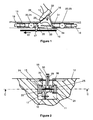
- the installation comprises a wire drive means 10, for example a cable or a chain, arranged in a closed loop housed in a gap 11 arranged in the ground 12.
- the gap 11 connects a departure zone and an arrival zone between which the installation carries out the transport of the persons.
- the wired drive means 10 is driven in a scrolling movement between the two zones, so that one of its strands goes from the departure zone to the arrival zone (see arrow 13).
- a motorization mechanism in the arrival zone and a tensioning mechanism in the starting zone or conversely a motorization mechanism in the starting zone and a tensioning mechanism in the starting zone. the arrival area. It is also conceivable to develop in the arrival zone a mechanism dedicated to both the motorization and the tensioning, the starting zone then being equipped with a fixed return mechanism.
- At least one pusher device is coupled to the wire drive 10 for propelling a foot 14 of the person during movement of the pusher device from the starting area to the area of arrival according to the arrow 13.
- each pusher device comprises a carriage 15, a thrust pedal 16, and a locking mechanism described below.
- the carriage 15 is equipped with a latching lug 17 to the wired drive means 10 and rolling means associated with guide means arranged in the ground 12 between the departure zone and the arrival zone.
- the trench-shaped gap 11 formed in the ground between the departure and arrival zones has forms adapted to receive the carriage 15.
- the rolling means comprise a pair of horizontal rollers 18, 19 arranged at the ends of the carriage in its displacement direction, and two pairs of vertical rollers 20 to 23.
- the pair of vertical rollers 20, 21 is positioned near the horizontal roller 18 towards the front of the carriage 15, while a pair of vertical rollers 22, 23 is positioned at the horizontal roller 19 towards the rear of the carriage 15.
- the horizontal rollers 18, 19 and vertical 20 to 23 roll in two lateral rails 24, 25 bordering the gap 11.
- Each lateral rail 24, 25 has a U-shaped section. open towards the side rail 24, 25 opposite. Potentially, the rails 24, 25 may have a curvature allowing the pusher device to move in a path having curves symbolized by the mark R on the figure 3 .
- the thrust pedal 16 has an active face 26 on which the foot 14 comes to bear during the propulsion operation starting simultaneously with the moving operation of the pusher device from the starting zone to the arrival zone.
- the thrust pedal 16 has a triangular shape in a vertical longitudinal plane and the active face 26 is constituted by the upper edge of this triangle.
- the foot 14 exerts a pressing force F ( figure 4 ) during the propulsion of the foot 14.
- the thrust pedal 16 is pivotally mounted on the carriage 15 to selectively occupy, during the movement of the carriage 15 from the starting zone to the arrival zone, a position protruding from the ground ( figure 1 and 4 ), a retracted position in the ground 12 inside the gap 11 ( figure 6 ).
- a light 27 is arranged through the carriage 15.
- the thrust pedal 16 In the protruding position of the ground, the thrust pedal 16 is positioned on one side of the light 27, generally on above the carriage 15. In the retracted position, the thrust pedal 16 is positioned on the other side of the light 27, generally below the carriage 15.
- the pivotal mounting of the thrust pedal 16 on the carriage 15 is realized using a hinge 28 provided in the front part of the thrust pedal 16, adapted to pivot the pedal 16 in a vertical longitudinal plane centered laterally on the carriage 15.
- a pawl 29 is pivotally mounted on the thrust pedal 16 according to a hinge 30 located in the upper part of the pedal, that is to say behind and above the hinge 28.
- the ratchet 29 is placed in a central housing of the pedal 16 defined by two lateral flanks of the pedal 16.
- the pawl has substantially a circular arc shape and the hinge 30 is arranged substantially in the middle of the arc. It has a convex upper edge facing upwards and a concave lower edge turned towards the bottom of the gap 11 through the light 27.
- a locking element 31 At the rear end of the pawl 29 is provided a locking element 31 arranged projecting longitudinally relative to the arched body of the pawl 29.
- the convex upper edge particularly in the portion of the pawl 29 in front of the hinge 30, has the possibility of projecting towards the top of the active face 26 of the pedal 13, by pivoting about the hinge 30, through a slot 32 arranged in the active face 26 and opening on the central housing of the pedal 16.
- a straight stroke return spring 33 is attached at one end to the pedal 16 at a point of attachment slightly rearward of the hinge 28, and at its opposite end to the pawl portion 29 located behind the hinge 30. .
- the length of the return spring 33 is chosen so that in its natural configuration, it keeps the pawl 29 in an angular position relative to the thrust pedal 16, such that the front portion of the convex upper edge of the pawl 29 is protruding from the active face 26 of the pedal 16.
- a pressing force F is applied to the active face 26, this force F has the effect of eliminating this projecting position relative to the active face 26, causing the pivoting of the pawl 29 relative to the pedal 16 around the hinge 30 and the passage of the return spring 33 to a deformed configuration (in this case by elongation) elastically with respect to its natural configuration.
- the return spring 33 constitutes means allowing the locking mechanism to automatically assume its inactive state in the absence of pressure force applied to the pedal 16 during the movement of the trolley from the departure area to the arrival area.
- the design of the pusher device could be modified within the scope of the invention, providing in particular that the pawl is articulated on the carriage and that the retaining element is integral with the thrust pedal.
- the return spring would be fixed at one end to the carriage and at its opposite end to the pawl.
- the mechanical transport installation comprises means for automatically placing the thrust pedal 16 in the protruding position of the ground when the pusher device passes to a first predetermined location situated in the starting zone or directly upstream thereof. the direction of movement of the pusher device.
- Such means are for example constituted by a ramp secured to the pedal 16 and intended to cooperate automatically with a fixed lift ramp arranged at said first location in the gap 11 at the time of passage of the pusher device at said first location.
- Such lifting means ensure that the thrust pedal 16 is already in position protruding from the ground when the pressing force F is likely to be applied in the starting area, then passing the locking mechanism to its active state.
- Such lifting means can indifferently be globally integrated on board the pusher device, for example by means of a motor controlling the pivoting of the pedal and controlled according to the position of the pusher device along the installation.
- a motor controlling the pivoting of the pedal and controlled according to the position of the pusher device along the installation.
- the passage of the thrust pedal 16 to the projecting position of the ground is controlled by the application of the pressing force F itself.
- the particularity of the pawl 29 to project from the active face 26 in the natural configuration of the return spring 33 constitutes means for putting the locking mechanism in its active state in the starting zone.
- these means being actuated by the application of a pressing force F on the pedal 16 to the passage of the pusher device in the starting zone.
- the application of a pressing force F controls the transition to the active state of the locking mechanism. It is clear that it may however be envisaged to provide means for putting the locking mechanism in its active state directly upstream of the departure zone in the direction of movement of the pusher device.
- the means for putting the locking mechanism in its active state would be automatically actuated by the passage of the pusher device to a second predetermined location located in the starting zone or upstream thereof in the direction of movement of the pusher device said second location being disposed downstream of the first location.
- the transition to the active state of the locking mechanism would be automatically performed before any subsequent application of a pressing force F in the starting area.
- the figure 5 illustrates that when the pressing force F ceases, the return spring 33 returns to its natural configuration, controlling the pivoting of the pawl 29 and the displacement of the movable blocking element 31 to a location where the movable blocking element 31 is no longer able to come into mechanical contact with the retaining element 34 when the pedal 16 tends to return to the retracted position, which is the case under the effect of gravity.
- the return spring 33 ensures the passage of the locking mechanism to its inactive state, eliminating any possibility of mechanical contact between the elements 31 and 34, and allowing the pedal to come to occupy its retracted position by pivoting under the effect of its proper weight ( figure 6 ).
- the return spring 33 thus constitutes elastic return means able to move the locking element 31 relative to the retaining element 34, and likely to occupy either a natural configuration in which the elements 31, 34 are not in contact, that is to say an elastically deformed configuration with respect to its natural configuration and in which the elements are in contact.
- Other modes of elastic deformation could be envisaged, such as torsion or compression.
- the transition from the natural configuration to the deformed configuration of the return spring 33 is controlled by the means for putting the locking mechanism in its active state, ie the application of a pressing force F, while the passage of the Deformed configuration with the natural configuration results, in the event of absence of pressure force F on the pedal, of the elasticity of the return spring 33.
- shutters 35, 36 can be arranged in the upper part of the gap 11 at the surface of the ground 12, with the aid of a mechanism for moving them laterally relative to the other, between a remote position providing access to the interior of the gap 11, and a close position in which their distal edges are placed at a spacing just enough to allow the longitudinal displacement of the thrust pedal 16.
- the mechanism may include means for returning the shutters 35, 36 to the close position, interposed either between the two shutters, or between each of the shutters and a vertical lateral flank dug in the ground.
- the pawl 29 is removed, but the fixed retention element 34 is always present at the rear of the pusher pedal 16.
- This is mounted on the carriage 15 in a connection mechanical providing, independently of one another, a free pivoting of horizontal lateral axis and a free translation of substantially longitudinal direction, of the pedal 16 relative to the carriage 15.
- the pedal can incorporate a oblong opening 37 inside which an axis 38 integral with the carriage 15 is mounted. The oblong opening 37 is arranged at the location of the articulation 28 of the first mode of production.
- the rectilinear return spring 33 is fixed at one end to a point of the pedal 16 in front of the oblong opening 37, and at its end opposite a point of the carriage 15 situated in front of the thrust pedal 16.
- the locking element 39 considered to be an integral part of the locking mechanism according to the invention, is for its part constituted by the lower rear end of the thrust pedal.
- the locking element belonging to the locking mechanism according to the invention can therefore be integral with a pawl independent of the pedal 16 or the carriage 15 as was the case in the first embodiment, but can also be integral with the pedal 16 itself, which is the case for this second embodiment.
- the locking mechanism it could be envisaged to make the locking element integral with the carriage 15. In this case, care should be taken to provide the retaining element integral with the thrust pedal 16.
- the length of the return spring 33 is chosen so that in its natural configuration, it keeps the pedal 16 in a longitudinal position with respect to the carriage 15 such that the locking element 39 and the retaining element 34 can not not come into mechanical contact with each other regardless of the angular position of the thrust pedal 16 relative to the carriage 15 about the axis 38.
- a pressing force F is applied to the active face 26, this effort F has the effect of causing a longitudinal recoil of the pedal 16, rearwardly, by sliding of the axis 38 in the oblong opening.
- This recoil of the pedal 16 involves the passage of the return spring 33 to a deformed configuration (in this case by elongation) elastically with respect to its natural configuration and the locking element 39 undergoes a displacement such that the elements 39 and 34 automatically come into contact with each other when the pedal 16 tends to move towards the retracted position, forcing it to stay in position protruding from the ground.
- the natural return of the return spring 33 to its natural configuration when the pressing force F stops causes the reverse movement of the pedal 16, releasing the locking element 39 relative to the retaining element 34 by eliminating any possibility of contact between the elements 34, 39 regardless of the angular position of the pedal 16 with respect to the carriage 15.
- the figure 8 illustrates that when the presser force F ceases, the return spring 33 returns to its natural configuration, controlling the longitudinal return of the pedal 16 forwards and the displacement of the locking element 39 to a location such that the locking element 39 is no longer able to come into mechanical contact with the retaining element 34 when the pedal 16 tends to return to the retracted position, which is the case under the effect of gravity.
- the return spring 33 ensures the passage of the locking mechanism to its inactive state, eliminating any possibility mechanical contact between the elements 39 and 34, and allowing the pedal to come to occupy its retracted position by pivoting under the effect of its own weight ( figure 9 ).
- the thrust pedal may comprise a frame pivotally mounted on the carriage in a first direction and a bearing flap pivotally mounted on the upper part of the frame in a second direction. perpendicular to the first.
- Such an assembly is intended to allow the support flap to occupy a position substantially perpendicular to the frame in which it can ensure the propulsion of a foot of the person during movement of the pusher device from the starting area to the arrival zone, a position substantially parallel to the chassis to allow the pedal to come to occupy its retracted position.
- the locking mechanism may comprise a pawl 40 forming the locking element, pivotally movable relative to the carriage between an upper position ( figure 10 ) after lifting by means of a suitable mechanism provided for in the departure zone, and a lower position ( figure 11 ) after natural lowering under the effect of gravity.
- the pawl 40 is arranged so that in the upper position, it blocks the pivoting of the pedal in the projecting position of the ground by mechanical contact with a fixed retaining element 41 integral with the pedal, temporarily forming a rigid mechanical connection eliminating the set of degrees of freedom between the pedal and the trolley.
- the pawl 40 is lowered, eliminating the mechanical contact between the pawl 40 and the retaining element 41 to allow the pedal to return to the retracted position.
- a locking mechanism designed such that the mechanical contact between the locking element and the element hold does not stop in the idle state.
- This is for example the case of a locking mechanism formed by the knee 42 of the Figures 12 and 13 .
- the figure 12 corresponds to an extended position of the toggle 42, unlike the figure 13 on which she occupies a bent position.
- the passage from the extended position to the bent position has the effect of breaking the rigid mechanical connection that conventionally provides the toggle 42 in the extended position.
- the passage from the bent position to the extended position is obtained by actuating a roller 43 from above, in opposition to the direction of deflection of the toggle joint 42. In the bent position, the locking and retaining elements remain in position.
Landscapes
- Engineering & Computer Science (AREA)
- Transportation (AREA)
- Mechanical Engineering (AREA)
- Mechanical Control Devices (AREA)
Applications Claiming Priority (1)
| Application Number | Priority Date | Filing Date | Title |
|---|---|---|---|
| FR0804695A FR2935331B1 (fr) | 2008-08-26 | 2008-08-26 | Installation mecanique pour le transport d'une personne sur une bicyclette ou analogue |
Publications (2)
| Publication Number | Publication Date |
|---|---|
| EP2159123A1 true EP2159123A1 (de) | 2010-03-03 |
| EP2159123B1 EP2159123B1 (de) | 2012-06-27 |
Family
ID=40459262
Family Applications (1)
| Application Number | Title | Priority Date | Filing Date |
|---|---|---|---|
| EP20090354034 Not-in-force EP2159123B1 (de) | 2008-08-26 | 2009-08-11 | Mechanische Anlage zum Transport einer Person auf einem Fahrrad oder Ähnlichem |
Country Status (3)
| Country | Link |
|---|---|
| EP (1) | EP2159123B1 (de) |
| ES (1) | ES2390745T3 (de) |
| FR (1) | FR2935331B1 (de) |
Families Citing this family (1)
| Publication number | Priority date | Publication date | Assignee | Title |
|---|---|---|---|---|
| CN108058695A (zh) * | 2017-12-19 | 2018-05-22 | 罗学中 | 一种共享单车的移车装置 |
Citations (2)
| Publication number | Priority date | Publication date | Assignee | Title |
|---|---|---|---|---|
| CA775898A (en) * | 1968-01-16 | Garbers Ernst | Arrangement for automating the release operation in a railroad marshalling yard | |
| US5566621A (en) | 1992-05-05 | 1996-10-22 | Wanvik; Jarle | Conveyor arrangement for rolling transport devices |
-
2008
- 2008-08-26 FR FR0804695A patent/FR2935331B1/fr not_active Expired - Fee Related
-
2009
- 2009-08-11 EP EP20090354034 patent/EP2159123B1/de not_active Not-in-force
- 2009-08-11 ES ES09354034T patent/ES2390745T3/es active Active
Patent Citations (2)
| Publication number | Priority date | Publication date | Assignee | Title |
|---|---|---|---|---|
| CA775898A (en) * | 1968-01-16 | Garbers Ernst | Arrangement for automating the release operation in a railroad marshalling yard | |
| US5566621A (en) | 1992-05-05 | 1996-10-22 | Wanvik; Jarle | Conveyor arrangement for rolling transport devices |
Also Published As
| Publication number | Publication date |
|---|---|
| FR2935331B1 (fr) | 2010-09-17 |
| ES2390745T3 (es) | 2012-11-16 |
| EP2159123B1 (de) | 2012-06-27 |
| FR2935331A1 (fr) | 2010-03-05 |
Similar Documents
| Publication | Publication Date | Title |
|---|---|---|
| CA2783595C (fr) | Element de separation pour cabine de plateforme comprenant un mecanisme a bielle de deplacement d'un ouvrant | |
| BE1014506A3 (fr) | Dispositif a volet avec element de reintroduction. | |
| FR2759408A1 (fr) | Dispositif de guidage pour un panneau coulissant et louvoyant d'obturation d'une baie | |
| FR2842467A1 (fr) | Systeme de plage arriere pour vehicule decouvrable a toit rigide repliable | |
| FR2495068A1 (fr) | Toit ouvrant pour vehicule | |
| CA2783523C (fr) | Element de separation pour cabine de plateforme comprenant un mecanisme a bielles de deplacement d'un ouvrant | |
| FR3101314A1 (fr) | Ensemble de marchepied pour véhicule de transport, véhicule ainsi équipé et procédé de mise en œuvre de ce véhicule | |
| EP0055166B1 (de) | Mechanische Triebketten- oder Riemenspanneinrichtung | |
| EP2159123B1 (de) | Mechanische Anlage zum Transport einer Person auf einem Fahrrad oder Ähnlichem | |
| EP2014864B1 (de) | Rollladen mit einer Anschlagvorrichtung zur Begrenzung der Aufrollung des Rollladenpanzers in den Rollladenkasten | |
| EP2694306B2 (de) | Glasdach mit verschiebbarer und schwenkbarer mobiler platte | |
| FR2881998A1 (fr) | Porte coulissante stable | |
| CH652936A5 (fr) | Fixation de securite pour ski. | |
| EP2072720A1 (de) | Abdichtvorrichtung einer Öffnung mit Hilfe eines beweglichen Paneels mit Verriegelungsrampe, und entsprechendes Kraftfahrzeug | |
| EP1420980B1 (de) | Verfahren zur steuerung der seitengeländer eines fahrzeugaufzugs und vorrichtung dafür | |
| FR2938586A1 (fr) | Structure de porte coulissante pour vehicule, et vehicule equipe d'une telle structure | |
| FR2764253A1 (fr) | Dispositif de marchepied mobile pour un vehicule automobile | |
| EP0034965B1 (de) | Antriebsvorrichtung für eine Schiebewand | |
| EP1927718B1 (de) | Vorrichtung zur Öffnungsbegrenzung einer Abdeckung und Verschluss- oder Sonnenschutzeinrichtung mit einer solchen Vorrichtung | |
| EP2042372A1 (de) | Ladeflächenvorrichtung mit Kipp- und Gleitmechanismus für Pannenhilfefahrzeug | |
| EP1442969B1 (de) | Raupenfahrzeug mit variablem Radstand | |
| EP2299039B1 (de) | Verriegelungs-/Entriegelungsvorrichtung eines Garagentors oder Ähnlichem | |
| FR2880842A1 (fr) | Porte laterale coulissante de vehicule automobile pourvue d'un marchepied embarque sur des moyens de support mobiles. | |
| FR2508092A1 (fr) | Dispositif formant baie comprenant un element de glace dit " basculant ", et vehicules, batiments equipes avec ce dispositif | |
| FR2859957A1 (fr) | Systeme de plage arriere pour vehicule decouvrable a toit rigide repliable |
Legal Events
| Date | Code | Title | Description |
|---|---|---|---|
| PUAI | Public reference made under article 153(3) epc to a published international application that has entered the european phase |
Free format text: ORIGINAL CODE: 0009012 |
|
| AK | Designated contracting states |
Kind code of ref document: A1 Designated state(s): AT BE BG CH CY CZ DE DK EE ES FI FR GB GR HR HU IE IS IT LI LT LU LV MC MK MT NL NO PL PT RO SE SI SK SM TR |
|
| AX | Request for extension of the european patent |
Extension state: AL BA RS |
|
| 17P | Request for examination filed |
Effective date: 20100826 |
|
| 17Q | First examination report despatched |
Effective date: 20100930 |
|
| GRAP | Despatch of communication of intention to grant a patent |
Free format text: ORIGINAL CODE: EPIDOSNIGR1 |
|
| GRAS | Grant fee paid |
Free format text: ORIGINAL CODE: EPIDOSNIGR3 |
|
| GRAA | (expected) grant |
Free format text: ORIGINAL CODE: 0009210 |
|
| AK | Designated contracting states |
Kind code of ref document: B1 Designated state(s): AT BE BG CH CY CZ DE DK EE ES FI FR GB GR HR HU IE IS IT LI LT LU LV MC MK MT NL NO PL PT RO SE SI SK SM TR |
|
| REG | Reference to a national code |
Ref country code: GB Ref legal event code: FG4D Free format text: NOT ENGLISH |
|
| REG | Reference to a national code |
Ref country code: CH Ref legal event code: EP |
|
| REG | Reference to a national code |
Ref country code: AT Ref legal event code: REF Ref document number: 564013 Country of ref document: AT Kind code of ref document: T Effective date: 20120715 |
|
| REG | Reference to a national code |
Ref country code: IE Ref legal event code: FG4D Free format text: LANGUAGE OF EP DOCUMENT: FRENCH |
|
| REG | Reference to a national code |
Ref country code: DE Ref legal event code: R096 Ref document number: 602009007877 Country of ref document: DE Effective date: 20120823 |
|
| PG25 | Lapsed in a contracting state [announced via postgrant information from national office to epo] |
Ref country code: SE Free format text: LAPSE BECAUSE OF FAILURE TO SUBMIT A TRANSLATION OF THE DESCRIPTION OR TO PAY THE FEE WITHIN THE PRESCRIBED TIME-LIMIT Effective date: 20120627 Ref country code: NO Free format text: LAPSE BECAUSE OF FAILURE TO SUBMIT A TRANSLATION OF THE DESCRIPTION OR TO PAY THE FEE WITHIN THE PRESCRIBED TIME-LIMIT Effective date: 20120927 Ref country code: FI Free format text: LAPSE BECAUSE OF FAILURE TO SUBMIT A TRANSLATION OF THE DESCRIPTION OR TO PAY THE FEE WITHIN THE PRESCRIBED TIME-LIMIT Effective date: 20120627 Ref country code: LT Free format text: LAPSE BECAUSE OF FAILURE TO SUBMIT A TRANSLATION OF THE DESCRIPTION OR TO PAY THE FEE WITHIN THE PRESCRIBED TIME-LIMIT Effective date: 20120627 |
|
| REG | Reference to a national code |
Ref country code: CH Ref legal event code: NV Representative=s name: CABINET ROLAND NITHARDT CONSEILS EN PROPRIETE INDU |
|
| REG | Reference to a national code |
Ref country code: NL Ref legal event code: VDEP Effective date: 20120627 |
|
| REG | Reference to a national code |
Ref country code: ES Ref legal event code: FG2A Ref document number: 2390745 Country of ref document: ES Kind code of ref document: T3 Effective date: 20121116 |
|
| REG | Reference to a national code |
Ref country code: LT Ref legal event code: MG4D Effective date: 20120627 |
|
| PG25 | Lapsed in a contracting state [announced via postgrant information from national office to epo] |
Ref country code: GR Free format text: LAPSE BECAUSE OF FAILURE TO SUBMIT A TRANSLATION OF THE DESCRIPTION OR TO PAY THE FEE WITHIN THE PRESCRIBED TIME-LIMIT Effective date: 20120928 Ref country code: LV Free format text: LAPSE BECAUSE OF FAILURE TO SUBMIT A TRANSLATION OF THE DESCRIPTION OR TO PAY THE FEE WITHIN THE PRESCRIBED TIME-LIMIT Effective date: 20120627 Ref country code: SI Free format text: LAPSE BECAUSE OF FAILURE TO SUBMIT A TRANSLATION OF THE DESCRIPTION OR TO PAY THE FEE WITHIN THE PRESCRIBED TIME-LIMIT Effective date: 20120627 Ref country code: HR Free format text: LAPSE BECAUSE OF FAILURE TO SUBMIT A TRANSLATION OF THE DESCRIPTION OR TO PAY THE FEE WITHIN THE PRESCRIBED TIME-LIMIT Effective date: 20120627 |
|
| PG25 | Lapsed in a contracting state [announced via postgrant information from national office to epo] |
Ref country code: SK Free format text: LAPSE BECAUSE OF FAILURE TO SUBMIT A TRANSLATION OF THE DESCRIPTION OR TO PAY THE FEE WITHIN THE PRESCRIBED TIME-LIMIT Effective date: 20120627 Ref country code: CZ Free format text: LAPSE BECAUSE OF FAILURE TO SUBMIT A TRANSLATION OF THE DESCRIPTION OR TO PAY THE FEE WITHIN THE PRESCRIBED TIME-LIMIT Effective date: 20120627 Ref country code: RO Free format text: LAPSE BECAUSE OF FAILURE TO SUBMIT A TRANSLATION OF THE DESCRIPTION OR TO PAY THE FEE WITHIN THE PRESCRIBED TIME-LIMIT Effective date: 20120627 Ref country code: EE Free format text: LAPSE BECAUSE OF FAILURE TO SUBMIT A TRANSLATION OF THE DESCRIPTION OR TO PAY THE FEE WITHIN THE PRESCRIBED TIME-LIMIT Effective date: 20120627 Ref country code: CY Free format text: LAPSE BECAUSE OF FAILURE TO SUBMIT A TRANSLATION OF THE DESCRIPTION OR TO PAY THE FEE WITHIN THE PRESCRIBED TIME-LIMIT Effective date: 20120627 Ref country code: IS Free format text: LAPSE BECAUSE OF FAILURE TO SUBMIT A TRANSLATION OF THE DESCRIPTION OR TO PAY THE FEE WITHIN THE PRESCRIBED TIME-LIMIT Effective date: 20121027 |
|
| BERE | Be: lapsed |
Owner name: POMAGALSKI Effective date: 20120831 |
|
| PG25 | Lapsed in a contracting state [announced via postgrant information from national office to epo] |
Ref country code: PL Free format text: LAPSE BECAUSE OF FAILURE TO SUBMIT A TRANSLATION OF THE DESCRIPTION OR TO PAY THE FEE WITHIN THE PRESCRIBED TIME-LIMIT Effective date: 20120627 Ref country code: PT Free format text: LAPSE BECAUSE OF FAILURE TO SUBMIT A TRANSLATION OF THE DESCRIPTION OR TO PAY THE FEE WITHIN THE PRESCRIBED TIME-LIMIT Effective date: 20121029 |
|
| PG25 | Lapsed in a contracting state [announced via postgrant information from national office to epo] |
Ref country code: NL Free format text: LAPSE BECAUSE OF FAILURE TO SUBMIT A TRANSLATION OF THE DESCRIPTION OR TO PAY THE FEE WITHIN THE PRESCRIBED TIME-LIMIT Effective date: 20120627 Ref country code: MC Free format text: LAPSE BECAUSE OF NON-PAYMENT OF DUE FEES Effective date: 20120831 |
|
| PG25 | Lapsed in a contracting state [announced via postgrant information from national office to epo] |
Ref country code: DK Free format text: LAPSE BECAUSE OF FAILURE TO SUBMIT A TRANSLATION OF THE DESCRIPTION OR TO PAY THE FEE WITHIN THE PRESCRIBED TIME-LIMIT Effective date: 20120627 |
|
| PLBE | No opposition filed within time limit |
Free format text: ORIGINAL CODE: 0009261 |
|
| STAA | Information on the status of an ep patent application or granted ep patent |
Free format text: STATUS: NO OPPOSITION FILED WITHIN TIME LIMIT |
|
| REG | Reference to a national code |
Ref country code: IE Ref legal event code: MM4A |
|
| PG25 | Lapsed in a contracting state [announced via postgrant information from national office to epo] |
Ref country code: BE Free format text: LAPSE BECAUSE OF NON-PAYMENT OF DUE FEES Effective date: 20120831 |
|
| 26N | No opposition filed |
Effective date: 20130328 |
|
| REG | Reference to a national code |
Ref country code: DE Ref legal event code: R097 Ref document number: 602009007877 Country of ref document: DE Effective date: 20130328 |
|
| PG25 | Lapsed in a contracting state [announced via postgrant information from national office to epo] |
Ref country code: BG Free format text: LAPSE BECAUSE OF FAILURE TO SUBMIT A TRANSLATION OF THE DESCRIPTION OR TO PAY THE FEE WITHIN THE PRESCRIBED TIME-LIMIT Effective date: 20120927 Ref country code: IE Free format text: LAPSE BECAUSE OF NON-PAYMENT OF DUE FEES Effective date: 20120811 |
|
| PG25 | Lapsed in a contracting state [announced via postgrant information from national office to epo] |
Ref country code: MT Free format text: LAPSE BECAUSE OF FAILURE TO SUBMIT A TRANSLATION OF THE DESCRIPTION OR TO PAY THE FEE WITHIN THE PRESCRIBED TIME-LIMIT Effective date: 20120627 |
|
| GBPC | Gb: european patent ceased through non-payment of renewal fee |
Effective date: 20130811 |
|
| PG25 | Lapsed in a contracting state [announced via postgrant information from national office to epo] |
Ref country code: TR Free format text: LAPSE BECAUSE OF FAILURE TO SUBMIT A TRANSLATION OF THE DESCRIPTION OR TO PAY THE FEE WITHIN THE PRESCRIBED TIME-LIMIT Effective date: 20120627 |
|
| PG25 | Lapsed in a contracting state [announced via postgrant information from national office to epo] |
Ref country code: LU Free format text: LAPSE BECAUSE OF NON-PAYMENT OF DUE FEES Effective date: 20120811 Ref country code: SM Free format text: LAPSE BECAUSE OF FAILURE TO SUBMIT A TRANSLATION OF THE DESCRIPTION OR TO PAY THE FEE WITHIN THE PRESCRIBED TIME-LIMIT Effective date: 20120627 |
|
| PG25 | Lapsed in a contracting state [announced via postgrant information from national office to epo] |
Ref country code: GB Free format text: LAPSE BECAUSE OF NON-PAYMENT OF DUE FEES Effective date: 20130811 Ref country code: HU Free format text: LAPSE BECAUSE OF FAILURE TO SUBMIT A TRANSLATION OF THE DESCRIPTION OR TO PAY THE FEE WITHIN THE PRESCRIBED TIME-LIMIT Effective date: 20090811 |
|
| PG25 | Lapsed in a contracting state [announced via postgrant information from national office to epo] |
Ref country code: MK Free format text: LAPSE BECAUSE OF FAILURE TO SUBMIT A TRANSLATION OF THE DESCRIPTION OR TO PAY THE FEE WITHIN THE PRESCRIBED TIME-LIMIT Effective date: 20120627 |
|
| REG | Reference to a national code |
Ref country code: FR Ref legal event code: PLFP Year of fee payment: 8 |
|
| REG | Reference to a national code |
Ref country code: FR Ref legal event code: PLFP Year of fee payment: 9 |
|
| REG | Reference to a national code |
Ref country code: FR Ref legal event code: PLFP Year of fee payment: 10 |
|
| PGFP | Annual fee paid to national office [announced via postgrant information from national office to epo] |
Ref country code: ES Payment date: 20200923 Year of fee payment: 12 Ref country code: FR Payment date: 20200824 Year of fee payment: 12 Ref country code: DE Payment date: 20200827 Year of fee payment: 12 |
|
| PGFP | Annual fee paid to national office [announced via postgrant information from national office to epo] |
Ref country code: CH Payment date: 20200821 Year of fee payment: 12 Ref country code: AT Payment date: 20200820 Year of fee payment: 12 Ref country code: IT Payment date: 20200806 Year of fee payment: 12 |
|
| REG | Reference to a national code |
Ref country code: DE Ref legal event code: R119 Ref document number: 602009007877 Country of ref document: DE |
|
| REG | Reference to a national code |
Ref country code: CH Ref legal event code: PL |
|
| REG | Reference to a national code |
Ref country code: AT Ref legal event code: MM01 Ref document number: 564013 Country of ref document: AT Kind code of ref document: T Effective date: 20210811 |
|
| PG25 | Lapsed in a contracting state [announced via postgrant information from national office to epo] |
Ref country code: LI Free format text: LAPSE BECAUSE OF NON-PAYMENT OF DUE FEES Effective date: 20210831 Ref country code: CH Free format text: LAPSE BECAUSE OF NON-PAYMENT OF DUE FEES Effective date: 20210831 Ref country code: AT Free format text: LAPSE BECAUSE OF NON-PAYMENT OF DUE FEES Effective date: 20210811 |
|
| PG25 | Lapsed in a contracting state [announced via postgrant information from national office to epo] |
Ref country code: IT Free format text: LAPSE BECAUSE OF NON-PAYMENT OF DUE FEES Effective date: 20210811 Ref country code: FR Free format text: LAPSE BECAUSE OF NON-PAYMENT OF DUE FEES Effective date: 20210831 Ref country code: DE Free format text: LAPSE BECAUSE OF NON-PAYMENT OF DUE FEES Effective date: 20220301 |
|
| REG | Reference to a national code |
Ref country code: ES Ref legal event code: FD2A Effective date: 20221102 |
|
| PG25 | Lapsed in a contracting state [announced via postgrant information from national office to epo] |
Ref country code: ES Free format text: LAPSE BECAUSE OF NON-PAYMENT OF DUE FEES Effective date: 20210812 |