EP2159146A1 - Motorrad mit einem Kühler und einer Batterie - Google Patents
Motorrad mit einem Kühler und einer Batterie Download PDFInfo
- Publication number
- EP2159146A1 EP2159146A1 EP08015267A EP08015267A EP2159146A1 EP 2159146 A1 EP2159146 A1 EP 2159146A1 EP 08015267 A EP08015267 A EP 08015267A EP 08015267 A EP08015267 A EP 08015267A EP 2159146 A1 EP2159146 A1 EP 2159146A1
- Authority
- EP
- European Patent Office
- Prior art keywords
- motorcycle
- battery
- empty space
- engine
- radiator
- Prior art date
- Legal status (The legal status is an assumption and is not a legal conclusion. Google has not performed a legal analysis and makes no representation as to the accuracy of the status listed.)
- Granted
Links
Images


Classifications
-
- B—PERFORMING OPERATIONS; TRANSPORTING
- B62—LAND VEHICLES FOR TRAVELLING OTHERWISE THAN ON RAILS
- B62K—CYCLES; CYCLE FRAMES; CYCLE STEERING DEVICES; RIDER-OPERATED TERMINAL CONTROLS SPECIALLY ADAPTED FOR CYCLES; CYCLE AXLE SUSPENSIONS; CYCLE SIDE-CARS, FORECARS, OR THE LIKE
- B62K11/00—Motorcycles, engine-assisted cycles or motor scooters with one or two wheels
- B62K11/02—Frames
- B62K11/04—Frames characterised by the engine being between front and rear wheels
-
- H—ELECTRICITY
- H01—ELECTRIC ELEMENTS
- H01M—PROCESSES OR MEANS, e.g. BATTERIES, FOR THE DIRECT CONVERSION OF CHEMICAL ENERGY INTO ELECTRICAL ENERGY
- H01M50/00—Constructional details or processes of manufacture of the non-active parts of electrochemical cells other than fuel cells, e.g. hybrid cells
- H01M50/20—Mountings; Secondary casings or frames; Racks, modules or packs; Suspension devices; Shock absorbers; Transport or carrying devices; Holders
- H01M50/249—Mountings; Secondary casings or frames; Racks, modules or packs; Suspension devices; Shock absorbers; Transport or carrying devices; Holders specially adapted for aircraft or vehicles, e.g. cars or trains
-
- B—PERFORMING OPERATIONS; TRANSPORTING
- B60—VEHICLES IN GENERAL
- B60R—VEHICLES, VEHICLE FITTINGS, OR VEHICLE PARTS, NOT OTHERWISE PROVIDED FOR
- B60R16/00—Electric or fluid circuits specially adapted for vehicles and not otherwise provided for; Arrangement of elements of electric or fluid circuits specially adapted for vehicles and not otherwise provided for
- B60R16/02—Electric or fluid circuits specially adapted for vehicles and not otherwise provided for; Arrangement of elements of electric or fluid circuits specially adapted for vehicles and not otherwise provided for electric constitutive elements
- B60R16/04—Arrangement of batteries
-
- F—MECHANICAL ENGINEERING; LIGHTING; HEATING; WEAPONS; BLASTING
- F01—MACHINES OR ENGINES IN GENERAL; ENGINE PLANTS IN GENERAL; STEAM ENGINES
- F01N—GAS-FLOW SILENCERS OR EXHAUST APPARATUS FOR MACHINES OR ENGINES IN GENERAL; GAS-FLOW SILENCERS OR EXHAUST APPARATUS FOR INTERNAL-COMBUSTION ENGINES
- F01N13/00—Exhaust or silencing apparatus characterised by constructional features
- F01N13/009—Exhaust or silencing apparatus characterised by constructional features having two or more separate purifying devices arranged in series
-
- F—MECHANICAL ENGINEERING; LIGHTING; HEATING; WEAPONS; BLASTING
- F01—MACHINES OR ENGINES IN GENERAL; ENGINE PLANTS IN GENERAL; STEAM ENGINES
- F01N—GAS-FLOW SILENCERS OR EXHAUST APPARATUS FOR MACHINES OR ENGINES IN GENERAL; GAS-FLOW SILENCERS OR EXHAUST APPARATUS FOR INTERNAL-COMBUSTION ENGINES
- F01N13/00—Exhaust or silencing apparatus characterised by constructional features
- F01N13/08—Other arrangements or adaptations of exhaust conduits
-
- F—MECHANICAL ENGINEERING; LIGHTING; HEATING; WEAPONS; BLASTING
- F01—MACHINES OR ENGINES IN GENERAL; ENGINE PLANTS IN GENERAL; STEAM ENGINES
- F01N—GAS-FLOW SILENCERS OR EXHAUST APPARATUS FOR MACHINES OR ENGINES IN GENERAL; GAS-FLOW SILENCERS OR EXHAUST APPARATUS FOR INTERNAL-COMBUSTION ENGINES
- F01N2340/00—Dimensional characteristics of the exhaust system, e.g. length, diameter or volume of the exhaust apparatus; Spatial arrangements of exhaust apparatuses
- F01N2340/04—Arrangement of the exhaust system relative to a vehicle or parts thereof
-
- F—MECHANICAL ENGINEERING; LIGHTING; HEATING; WEAPONS; BLASTING
- F01—MACHINES OR ENGINES IN GENERAL; ENGINE PLANTS IN GENERAL; STEAM ENGINES
- F01N—GAS-FLOW SILENCERS OR EXHAUST APPARATUS FOR MACHINES OR ENGINES IN GENERAL; GAS-FLOW SILENCERS OR EXHAUST APPARATUS FOR INTERNAL-COMBUSTION ENGINES
- F01N2590/00—Exhaust or silencing apparatus adapted to particular use, e.g. for military applications, airplanes, submarines
- F01N2590/04—Exhaust or silencing apparatus adapted to particular use, e.g. for military applications, airplanes, submarines for motorcycles
-
- Y—GENERAL TAGGING OF NEW TECHNOLOGICAL DEVELOPMENTS; GENERAL TAGGING OF CROSS-SECTIONAL TECHNOLOGIES SPANNING OVER SEVERAL SECTIONS OF THE IPC; TECHNICAL SUBJECTS COVERED BY FORMER USPC CROSS-REFERENCE ART COLLECTIONS [XRACs] AND DIGESTS
- Y02—TECHNOLOGIES OR APPLICATIONS FOR MITIGATION OR ADAPTATION AGAINST CLIMATE CHANGE
- Y02E—REDUCTION OF GREENHOUSE GAS [GHG] EMISSIONS, RELATED TO ENERGY GENERATION, TRANSMISSION OR DISTRIBUTION
- Y02E60/00—Enabling technologies; Technologies with a potential or indirect contribution to GHG emissions mitigation
- Y02E60/10—Energy storage using batteries
Definitions
- the present invention relates to the field of motorcycles.
- the present invention relates to the layout of motorcycles.
- the present invention relates to the location, disposition and dimension of component parts of a motorcycle such as, for instance, the battery and the radiator.
- the present invention relates to the way the performances of several component parts and/or elements of a motorcycle can be improved and optimized by conveniently locating and disposing said component parts.
- batteries when batteries are located close to heat generating component parts such as, for instance, the engine or the exhaust pipe, the batteries could get overheated and finally damaged. It also has to be considered that batteries, in spite of their non-negligible dimensions, have a weight which is normally less than that of other component parts with similar dimensions. Accordingly, the location of the battery in a motorcycle with respect to other component parts also influences the balancing of the motorcycle. Inadequate balancing could influence the traveling performance and also annoy the driver and/or passenger of the motorcycle. It also has to be noted that the air stream or air flow generated during traveling, in particular at high speeds, is used for cooling several motor parts or components such as, for instance, the radiator, the cylinder or even the exhaust pipes.
- a big battery located for instance in the front portion of the motorcycle would represent an obstacle to the air flow, resulting in these component parts or elements getting overheated.
- catalysts exploit their function (capturing the polluting components of the exhaust gases) only if their temperature is comprised between a predefined range (the activation temperature range is usually comprised between 550 and 650 degrees); a catalyst placed behind (in the traveling direction) a big or cumbersome battery would not experience the cooling effect arising during travel due to the resulting air stream or air flow.
- the same considerations as stated above with respect to catalysts also apply for instance to the cylinder of the motorcycle. It is in fact well-known that cylinders are cooled by means of both the cooling liquid flowing from the radiator and the air stream arising during travel.
- radiator In the case of the radiator, difficulties are normally faced during design of the motorcycle due to the relevant dimensions of the radiator and the important function to be exploited by same. Large radiators would guarantee adequate cooling of the coolant fluid but would influence the overall layout of the motorcycle. The motorcycle would become too cumbersome and it would also be difficult to find an adequate location for other component parts. Moreover, the radiator would also represent an obstacle to the air flow arising during travel, so that other component parts of the motorcycle located behind the radiator could become overheated.
- radiators were placed in the front portion of the motorcycle, in particular before the engine. In this way, the engine can still experience the cooling effect produced by the air flow arising during travel; however, small radiators mean reduced quantity of cooling fluid, which means in turn reduced cooling performances.
- a further solution relating to the structure disposition and location of a battery in a motorcycle is disclosed in, for example, Japanese Patent Application Laid Open Gazette No. 2001-71961 .
- a battery is arranged beneath a seat.
- the battery is accommodated in an empty space defined by the seat and a receiving recess, which is formed by a rear fender covering an upper portion of a rear wheel.
- an object of the present invention to overcome the problems stated above.
- the present invention is based on the consideration that the problems affecting the prior art motorcycles may be overcome by adequately arranging, designing and dimensioning some component parts of the motorcycle, in particular the battery.
- the battery which is normally perceived as an encumbering component part may be opportunely arranged, according to the present invention so as to allow quick mounting and maintenance operation as well as performance and reliability of the battery.
- a further consideration on which the present invention is based relates to the fact that both the battery and the radiator, if opportunely designed and dimensioned, may be placed in the front portion of the motorcycle (before the engine and/or cylinder), without representing an obstacle to the air flow so that component parts located behind said battery and radiator can be adequately cooled. Moreover, even the cooling of both the radiator and the battery is improved when same are placed before the engine or cylinder.
- the empty space that opens to the front of the vehicle is provided inside the front cover, and the battery is provided such that at least a part of the battery is disposed within the empty space.
- Moving air is introduced into the empty space during traveling. The moving air suppresses the increase of temperature caused by the heat generated from the battery, and as a result, the durability (life) of the battery can be improved.
- the present invention is understood to be of particular advantage when applied to two-wheeled motorcycles, such as, for instance, motorbikes or the like.
- two-wheeled motorcycles such as, for instance, motorbikes or the like.
- examples will be given in the following, in which corresponding embodiments of the exhaust gas purifying apparatus or system according to the present invention are applied to motorcycles, in particular, to motorbikes.
- the applications of the exhaust gas purifying apparatus or system according to the present invention are not limited to the case of motorcycles, in particular, to the case of motorbikes; on the contrary, the exhaust has purifying apparatus or system according to the present invention may also be applied to other motorcycles, in particular, to three or even four-wheeled motorcycles such as, for instance, choppers, quads or the like.
- reference numeral "1" identifies a equipped with an exhaust gas apparatus motorcycle according to a first embodiment of the present invention.
- the motorcycle 1 comprises a vehicle frame 2, a front fork 3, an engine 4, a fuel tank 5, a rear arm 6, a rear-wheel suspension system 7, a seat 8, an exhaust system 9, and a vehicle cover 12.
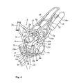
- the front fork 3 is supported by the head pipe 2a (see also Figure 4 ) to be steerable to the left and right.
- a front wheel 10 is supported by the lower end of the front fork 3, and a steering handle 11 is fixed to the upper end thereof.
- the fuel tank 5 is of an integrated type and is integrated by welding flanges formed on the peripheries of an upper tank and a lower tank. Moreover, a recovery tank 35 is provided between the left and right seat rails 2f. 2f and in the empty space defined on the left side of the air cleaner 13d.
- the recovery tank 35 is for storing the amount of cooling water expanded in radiator 27 described below when the temperature of cooling water increases, and for supplying the amount of cooling water contracted when the temperature thereof decreases.
- the recovery tank 35 is provided in a region surrounded by the left seat rail 2f, the left seat stay 2g, and the main frame 2b, and is formed such that the left side wall 35b (see also figure 7 ), thereof is protruded slightly outward to the left. With this structure, the required volume is maintained.
- the rear arm 6 is supported by a pivot axis 6a, which is inserted through the lower end of the rear arm bracket 2e, such that the rear arm 6 is pivotable upward and downward, and a rear wheel 14 is supported at the rear end of the rear arm 6.
- the seat 8 is provided such that it covers the upper surface of the rear part of the fuel tank 5, extends backward therefrom, and is removably mounted on the left and right seat rails 2f, 2f.
- the motorcycle 1 comprises a vehicle cover 12 covering the main section of the vehicle (see also Figures 7 and 8 ).
- the vehicle cover 12 is composed of a front cover 23 covering the left and right side surfaces of the fuel tank 5 and the main frames 2b, 2b and the upper surface of the fuel tank 5; a rear cover 24 covers the left and right side surfaces of a rear portion of the seat 8 and the rear portion of the seat 8; a center cover 25 disposed between the rear cover 24 and the front cover 23 covers the left and right side portions of the front portion of the seat 8.
- Each cover 23 to 25 is sub-assembled to the vehicle in advance, and is attached to the vehicle by fastening the main parts with fastening member such as bolts connectors, screws or the like.
- the front cover 23 covers the main frames 2b, 2b and the downtube 2c from the sides and creates a space in the width direction of the vehicle such that empty spaces A, A' that open to the front are formed between the side surfaces of the main frames 2b, 2b and the downtube 2c. Moreover, the front cover 23 has forward extension portions 23a, 23a which extend diagonally outward and forward to be provided on left and right sides of the front fork 3. Thus, the empty spaces A, A' widen as they approach the front of the vehicle.
- the forward extension portions 23a serve as wind deflectors for introducing moving air into the empty spaces A, A'.
- moving air is introduced into the empty spaces A, A' through openings 23b, 23b as the motorcycle travels.
- left and right main frames tubes 2b, 2b are connected to an upper portion of a head pipe 2a which is provided at the front end of the vehicle frame 2.
- the left and right main frames 2b, 2b extend diagonally backward and downward while spreading outward from the upper portion in the width direction of the vehicle.
- a downtube 2c is connected to a lower portion of the head pipe 2a, and left and right undertubes 2d, 2d are connected to the lower end of the downtube 2c.
- the left and right undertubes 2d, 2d extend downward and further backward while spreading outward, and are connected to the lower ends of rear arm brackets 2e, 2e of the main frames tubes 2b, 2b.
- left and right seat rails 2f, 2f are connected to the middle parts of the main frames tubes 2b, 2b, and the seat rails extend substantially horizontally backward.
- the middle parts of the left and right seat rails 2f, 2f are connected to the rear arm brackets 2e via seat stays 2g.
- the seat stays 2g have a function of enhancing the load bearing rigidity of the seat rails 2f.
- the engine 4 is provided within an empty space (cradle) surrounded by the main frames tubes 2b of the vehicle frame 2, the rear arm brackets 2e, the downtube 2c and the undertubes 2d, and is removably fixed to these frame members via suspension bolts.
- the engine 4 may be a water-cooling, four-cycle single cylinder engine. However, according to the needs and/or circumstances, other engines are possible such as, for instance, multiple cylinder engines.
- a cylinder body 4b, a cylinder head 4c, and a head cover 4d are stacked and coupled to an upper surface of the front portion of a crankcase 4a which is integrated with a transmission case 4e.
- the cylinder body 4b, the cylinder head 4c and the head cover 4d are provided in a forward tilting state such that the upper portion of a cylinder axis a is tilted toward the front.
- the crankcase 4a comprises a front wall 4a' with flat left and right side portions.
- the front wall 4a' has been depicted in Figure 5 only for the sake of clarity; accordingly, only the flat left portion thereof can be identified in Figure 5 . It has, however, to be considered that the front wall 4a' of the crankcase 4a also comprises a right flat portion opposite to said flat left portion in the transverse direction of the motorcycle. As apparent from Figure 5 , said left and right flat portions of said front wall 4a' are tilted toward the back, i.e. with the upper portions thereof being tilted toward the back.
- the central axis C2 of the catalyst 18 (and the receiving portion 15b), and said flat portions of the front wall 4a' are tilted at predefined angles with respect to the vertical; according to a preferred embodiment of the present invention, said central axis C2 and said flat and right portions are tilted at the same angle, with said central axis C2 being parallel to said left and right flat portions.
- the fuel tank 5 is disposed such that, in a plain view, it is positioned between the left and right main frames 2b, 2b.
- a suction system 13 is connected to the back wall of the cylinder head 4c of the engine 4.
- the suction system 13 has a throttle body 13b which is connected to a suction port that opens on the back wall via a joint member 13a, and an air cleaner 13d connected to the throttle body 13b via a suction duct 13c.
- the air cleaner 13d is disposed such that it is positioned beneath the seat 8 and between the left and right seat rails 2f, 2f and is deviated to the right.
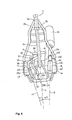
- the exhaust gas system 9 comprises a main exhaust pipe 15, which is connected to an exhaust port 4f that opens on the front wall of the cylinder head 4c, and a silencer (muffler) 16, which is connected to the rear end portion of the main exhaust pipe 15.
- the main exhaust pipe 15 extends diagonally forward from the cylinder head 4c toward one side (right side) of the motorcycle in the width direction and extends downward, passes in front of the engine to the other side (left side), and further extends upward and then backward.
- a first catalyst 17 is received in a first portion 15a of the main pipe 15 extending downward, and a second catalyst 18 is received in a second portion 15b of said main pipe 15 extending upwards.
- the first portion 15a and the second portion 15b are provided in a tilted state where, when viewed from the front of the vehicle, the lower portions thereof are tilted inward in the width direction of the vehicle.
- an axis line c1 of the first extension portion 15a has a tilt angle ⁇ 1 with respect to the central line L of the vehicle
- an axis line c2 of the second extension portion 15b has a tilt angle ⁇ 2 with respect to the central line L of the vehicle, so that the axis lines c1, c2 form a V-shape.
- the first portion 15a when viewed from the right of the vehicle, the first portion 15a is provided in a forward tilting state such that the upper portion thereof is tilted toward the front of the vehicle, and the second portion 15b is provided in a backward tilting state such that the upper portion thereof is tilted toward the rear of the vehicle.
- the axis line c1 of the first portion 15a is parallel to the forward tilting cylinder axis line a
- the axis line c2 of the second extension portion 15b is parallel to the backward tilting front wall 4a' of the crankcase 4a so that the axis lines c1, c2 form a V-shape as a whole.
- a backward extension portion 15d leading from the second portion 15b extends backward on the inside of the left main frame 2b and the left seat stay 2g, and raises upward near the seat stay 2g.
- the silencer 16 is connected to the upper end portion of such raised portion 15e.
- the silencer 16b is fixed to the left seat rail 2f via a bracket 16a.
- the backward extension portion 15d is divided into front and rear portions along the way, which are removably connected via a joint member 15f. Furthermore, an oxygen sensor 38 is mounted near the joint member 15f of the backward extension portion 15d.
- the oxygen sensor 38 is disposed such that, when viewed from the side of the vehicle, it extends toward the front more than the left main frame tube 2b and toward the back more than the cylinder body 4b. In other words, the oxygen sensor 38 is provided such that it is not interfered by the main frame tubes 2b during maintenance from the sides of the vehicle.
- the oxygen sensor 38 is disposed at a location that is not readily exposed to the heat from cylinder body 4b and cylinder head 4c.
- the exhaust gas system 15 of the present invention further comprises a secondary air supply system 19.
- This secondary air supply system 19 will be described in the following with reference to Figures 4 to 6 , and 9 .
- the secondary air supply system 19 comprises a secondary air supply tube 20 connecting the exhaust pipe 15 and the air cleaner 13b, and an on-off valve (lead valve) 21 that opens and closes the secondary air supply tube 20.
- the secondary air supply tube 20 extends in a front-back direction, and passes through one side (right side) of the vehicle in the width direction above the upper wall 4g of the crankcase 4a and on the right side of the cylinder body 4b, therefore on the opposite side of the backward extension portion 15d of the exhaust pipe 15.
- An upstream end portion 20a of the secondary air supply tube 20 is connected to the air cleaner 13d, and a downstream end portion 20b thereof is connected, from above, to an engine-front extension portion 15c, which is located between the first and second portions 15a, 15b of the exhaust pipe 15.
- the downstream end portion 20b of the pipe 20 is connected to the engine-front extension portion 15c of the main pipe 15 at a position located in the rear half c of said engine-front extension portion 15c facing toward the engine.
- the engine-front extension portion 15c may be regarded as being divided by a vertical plane B receiving the center axis a' of said engine-front extension portion 15c into a first semicircular half C (depicted in an enlarged view in Figure 9 ) facing the engine or crankcase and a second semicircular half facing toward the front.
- the secondary air pipe or tube 20 or, in particular, the downstream end portion 20b thereof is connected to the engine-front extension portion 15c at a position located in the first semicircular half thereof, namely in the semicircular half thereof facing toward the rear of the motorcycle, in particular, facing towards the crankcase and the engine.
- the on-off valve 21 is fixed at a portion close to the cylinder and above the upper wall 4g of the crankcase 4a via a bracket 22.
- the on-off valve 21 serves as a check valve which allows the air to flow only from the air cleaner 13d side to the exhaust pipe 15 side and prevents an opposite flow. Therefore, air is introduced into the exhaust pipe 15 due to negative pressure caused by pulsation of exhaust gas, while the exhaust gas within the exhaust pipe 15 is prevented from flowing out.
- a first catalyst 17 is received in main exhaust gas pipe 15 of an exhaust system 9 within a first receiving portion 15a located in front of the engine 4 and to the right of the motorcycle in the width direction, and a second catalyst 18 is received within a second receiving portion 15b located in front of the engine 4 and to the left.
- the first and second catalysts 17, 18 are promptly activated by the heat from the engine when the engine is started.
- a secondary air supply tube 20 is connected to the front extension portion 15c of the exhaust pipe 15 located in front of the engine and between the receiving portions 15a, 15b in which the first and second catalysts 17, 18 are disposed, purification of HC and CO by the second catalyst 18 can be accelerated. As a result, purification efficiency of exhaust gas in an extended engine operating region included during the starting of the engine can be improved.
- downstream end 20b of the secondary air supply tube 20 is connected to the engine-front extension portion 15c of the exhaust pipe 15 at a position located in the semicircular portion C thereof, which is closer to the engine than the vertical plane B passing through the center of axis a of the engine front extension portion 15c, exhaust pipe connecting portion 20b of the secondary air supply tube 20 is less likely to be hit by stones thrown up by the front wheel 10.
- first catalyst 17 is disposed within the first receiving portion 15a extending downward of the exhaust pipe 15 and the second catalyst 18 is disposed within the second receiving portion 15b extending upward, thus the first and second catalysts 17, 18 are vertically disposed, allocation space for the catalysts (length of exhaust pipe) is more readily secured, as compared to the case where two exhaust pipes are arranged in series in the portion extending in the horizontal direction.
- first receiving portion 15a is tilted forward and the second receiving portion 15b is tilted backward, the main exhaust pipe is longer than in the case where it is extended directly downwards, and allocation gas space for the catalysts is more readily secured.
- first receiving portion 15a and the second receiving portion 15b are provided such that they tilt laterally outward, allocation space for the catalysts (length of exhaust pipe) is even more readily secured. In this case the tilting angle, as the vehicle is being titled during cornering, can be increased.
- the backward extension portion 15d of the exhaust pipe 15 is disposed such that it passes through the left side of the vehicle in the width direction
- the secondary air supply tube 20 is disposed such that it passes through the right side of the vehicle in the width direction, thus the opposite side of the exhaust pipe, the secondary air supply tube 20 is not exposed to the heat from the exhaust pipe 15.
- the middle part of the secondary air supply tube 20 is fixed to the upper wall 4g of the crankcase 4a, damage of the secondary air supply tube 20 caused by, for example, hitting the side of the cylinder body 4b due to the vibration generated by the pulsation of the secondary air can be prevented. Moreover, since it also serves a dual purpose of fixing the check valve 21 located along the secondary air supply tube 20 and as a steady brace for the secondary air supply tube 20, a simple structure is achieved.
- a radiator 27 is provided on the side (left side) of the downtube 2c in the width direction of the vehicle.
- the radiator 27 is mounted on the downtube 2c by means of a bracket 28 such that it is disposed on the left side of the downtube 2c.
- An upper portion 27a of the radiator 27 is located within the left empty space A'.
- reference numeral "27b" identifies a louver, which is provided on the front surface of the radiator 27 (the surface facing toward the front of the motorcycle) and prevents mud or the like from being attached to the radiator 27.
- the louver 27b is structured such that it does not inhibit the introduction of the moving air into the radiator 27.
- the radiator (27), which is located on the left side of the vehicle in the width direction, and the recovery tank 35, which is provided on the same left side, are communicatively connected by a recovery hose or pipe 36, which is provided to extend in the front-back direction on the left side of the vehicle in the width direction.
- a battery 30 is provided in a battery case 31 within the right empty space A.
- the battery case 31 is in a box shape and has an opening 31 a that opens to the front.
- the battery case 31 is removable with respect to the bracket 32 fixed to the downtube 2c or the main frame 2b.
- a cover plate 33 is removably mounted on the opening 31 a.
- the cover plate 33 serves as a protection wall for preventing stones or the like from hitting the battery 30. It has, however, to be noted that according to the needs and/or circumstances, instead of simple plates, a louver, a mesh plate or a perforated plate for promoting the introduction of the traveling wind into the battery case 31 can be used as a protection wall.
- a further protection plate (not depicted in the drawings) supported either by the vehicle frame or by the vehicle cover, can be employed as the protection wall for preventing stones or the like from hitting the battery 30.
- a power line 30a connected to the battery 30 and a fuse box 34 provided along the power line 30a and serving as an electric part or equipment are provided between the battery 30 and the cover plate 33 within the battery case 31.
- the battery 30 can be mounted on the bracket 32 in a sub-assembled state where the power line 30a, the fuse box 34 and the like are being connected and disposed within the battery case 31.
- the front cover 23 constituting the front portion of the vehicle cover 12 covers at least partially the downtube 2c, the main frame 2b and thus the fuel tank 5 so as to create a space in the width direction of the vehicle so that the empty space A that opens to the front is formed. Therefore, moving air is introduced into the empty space A while traveling. Since the battery 30 is provided within the empty space A, the battery 30 is cooled by the moving air, and the increase in temperature caused by the heat generated from the battery 30 can be suppressed. As a result, the durability (life) of the battery 30 can be improved.
- cover plate 33 serving as a protection wall is provided on the front surface of the battery 30, stones or the like can be prevented from hitting the battery 30. This can also improve the durability and life of the battery.
- the cover plate 33 which opens and closes the opening 31a of the battery case 31, is used as a protection wall, the battery 30 can be protected from stepping stones or the like with the simple structure.
- the battery 30, the fuse box 34 and the like which are sub-assembled within the battery case 31 is removable with respect to the bracket 32. Therefore, the workability when the battery 30 is disposed within the empty space A can be improved.
- an empty space A' is also formed on the left side of the downtube 2c; the radiator 27 is provided on the left side of the motorcycle, and an upper portion 27a of the radiator 27 is received within the empty space A'. Therefore, when the relatively heavy battery 30 is provided within the right empty space A, left and right weights can be well balanced while improving the cooling performance of the radiator 27.
- the recovery tank 35 may be located as depicted in Figures 7 and 8 beneath the seat 8 and on the left side of the air cleaner 13d; accordingly, the recovery hose 36, connects the recovery tank 35 and the radiator 27, may be provided as depicted in Figures 7 and 8 so as to extend along the left side of the motorcycle in the width direction. Therefore, the piping configuration can be simplified while disposing the recovery tank 35 away from the radiator 27.
- the recovery tank 35 and the air cleaner 13d are located in the region surrounded by the seat rail 2f and the seat stay 2g, thus partially beneath and partially in front of the seat (8). Therefore, thickness of an upper portion of the rear fender 37 (see Figure 1 ) provided over the rear wheel 14 can be reduced, and freedom in design, for example simple design of the portion over the rear wheel, can be enhanced.
- the battery 30 is provided within the right empty space A, and the exhaust pipe 15 extends backward through the left side of the vehicle in the width direction.
- the exhaust pipe 15 is provided on the opposite side of the battery 30, it is possible to prevent the heat of the exhaust pipe 15 from having adverse effects on the battery 30. As a result, the cooling performance of the battery can be maintained and the durability of the battery can be increased.
- the battery 30 is provided inward of the front cover 23, it is not necessary to dispose the battery beneath the seat 8. Thus, even when a rear portion of the exhaust pipe 15 is raised upward beneath the seat 8, the battery is not exposed to the heat of the exhaust pipe. As a result, for example, the so-called up-muffler structure can be employed without any problem, and a degree of freedom of the exhaust pipe configuration can be increased.
- the battery case 31 and the battery 30 are provided in the right empty space A, the battery case 31 and the battery 30 can also be provided in the left empty space A' without departing from the scope of the present invention.
- the entire battery case 31 and battery 30 are provided in the empty space A.
- the present invention allows the drawbacks and all problems affecting the prior art solutions relating to the layout and reciprocal disposition of the battery and/or the radiator in a motorcycle to be overcome or at least strongly reduced or minimized.
- the present invention offers evident advantages in terms of improved reliability, efficiency and performance of the battery of a motorcycle.
- the particular location of the battery according to the present invention allows to avoid overheating of the battery since no risk is run for the battery to get overheated by the exhaust gas pipe.
- the battery is adequately protected by the cover of the motorcycle.
- the present solution is quite convenient in terms of space being saved so that no space is unduly lost but the space usually occupied by the battery can be used for conveniently locating other component parts and/or accessories of the motorcycle.
Landscapes
- Engineering & Computer Science (AREA)
- Chemical & Material Sciences (AREA)
- Mechanical Engineering (AREA)
- Aviation & Aerospace Engineering (AREA)
- Chemical Kinetics & Catalysis (AREA)
- Electrochemistry (AREA)
- General Chemical & Material Sciences (AREA)
- Combustion & Propulsion (AREA)
- General Engineering & Computer Science (AREA)
- Automatic Cycles, And Cycles In General (AREA)
Priority Applications (4)
| Application Number | Priority Date | Filing Date | Title |
|---|---|---|---|
| AT08015267T ATE490162T1 (de) | 2008-08-29 | 2008-08-29 | Motorrad mit einem kühler und einer batterie |
| EP08015267A EP2159146B1 (de) | 2008-08-29 | 2008-08-29 | Motorrad mit einem Kühler und einer Batterie |
| ES08015267T ES2355417T3 (es) | 2008-08-29 | 2008-08-29 | Motocicleta que comprende un radiador y una batería. |
| DE602008003804T DE602008003804D1 (de) | 2008-08-29 | 2008-08-29 | Motorrad mit einem Kühler und einer Batterie |
Applications Claiming Priority (1)
| Application Number | Priority Date | Filing Date | Title |
|---|---|---|---|
| EP08015267A EP2159146B1 (de) | 2008-08-29 | 2008-08-29 | Motorrad mit einem Kühler und einer Batterie |
Publications (2)
| Publication Number | Publication Date |
|---|---|
| EP2159146A1 true EP2159146A1 (de) | 2010-03-03 |
| EP2159146B1 EP2159146B1 (de) | 2010-12-01 |
Family
ID=39832489
Family Applications (1)
| Application Number | Title | Priority Date | Filing Date |
|---|---|---|---|
| EP08015267A Active EP2159146B1 (de) | 2008-08-29 | 2008-08-29 | Motorrad mit einem Kühler und einer Batterie |
Country Status (4)
| Country | Link |
|---|---|
| EP (1) | EP2159146B1 (de) |
| AT (1) | ATE490162T1 (de) |
| DE (1) | DE602008003804D1 (de) |
| ES (1) | ES2355417T3 (de) |
Citations (5)
| Publication number | Priority date | Publication date | Assignee | Title |
|---|---|---|---|---|
| JPH08127377A (ja) * | 1994-10-31 | 1996-05-21 | Suzuki Motor Corp | スクータ型車両のラジエータ配置構造 |
| JP2001071961A (ja) | 1999-09-01 | 2001-03-21 | Honda Motor Co Ltd | 自動二輪車 |
| EP1598230A1 (de) * | 2004-05-18 | 2005-11-23 | HONDA MOTOR CO., Ltd. | Batteriebefesftigung |
| US20080006463A1 (en) * | 2006-06-05 | 2008-01-10 | Yamaha Hatsudoki Kabushiki Kaisha | Motorcycle with battery mounting arrangement |
| JP2008080986A (ja) * | 2006-09-28 | 2008-04-10 | Honda Motor Co Ltd | バッテリ搭載機構 |
-
2008
- 2008-08-29 ES ES08015267T patent/ES2355417T3/es active Active
- 2008-08-29 AT AT08015267T patent/ATE490162T1/de not_active IP Right Cessation
- 2008-08-29 EP EP08015267A patent/EP2159146B1/de active Active
- 2008-08-29 DE DE602008003804T patent/DE602008003804D1/de active Active
Patent Citations (5)
| Publication number | Priority date | Publication date | Assignee | Title |
|---|---|---|---|---|
| JPH08127377A (ja) * | 1994-10-31 | 1996-05-21 | Suzuki Motor Corp | スクータ型車両のラジエータ配置構造 |
| JP2001071961A (ja) | 1999-09-01 | 2001-03-21 | Honda Motor Co Ltd | 自動二輪車 |
| EP1598230A1 (de) * | 2004-05-18 | 2005-11-23 | HONDA MOTOR CO., Ltd. | Batteriebefesftigung |
| US20080006463A1 (en) * | 2006-06-05 | 2008-01-10 | Yamaha Hatsudoki Kabushiki Kaisha | Motorcycle with battery mounting arrangement |
| JP2008080986A (ja) * | 2006-09-28 | 2008-04-10 | Honda Motor Co Ltd | バッテリ搭載機構 |
Also Published As
| Publication number | Publication date |
|---|---|
| DE602008003804D1 (de) | 2011-01-13 |
| ES2355417T3 (es) | 2011-03-25 |
| ATE490162T1 (de) | 2010-12-15 |
| EP2159146B1 (de) | 2010-12-01 |
Similar Documents
| Publication | Publication Date | Title |
|---|---|---|
| JP5879346B2 (ja) | 鞍乗型車両 | |
| EP2159393B1 (de) | Abgasreinigungsvorrichtung für ein Motorrad und mit einer solchen Abgasreinigungsvorrichtung ausgestattetes Motorrad | |
| EP3002204B1 (de) | Sattelfahrzeug | |
| US7347296B2 (en) | Front structure of all terrain vehicle | |
| US8113312B2 (en) | Evaporative emissions canister arrangement for a motorcycle, and motorcycle incorporating same | |
| US9919756B2 (en) | Saddle-ride type vehicle | |
| EP2075179B1 (de) | Motorrad | |
| CN110030124B (zh) | 跨骑型车辆的过滤罐配置结构 | |
| EP2159146B1 (de) | Motorrad mit einem Kühler und einer Batterie | |
| EP2159145B1 (de) | Anordnung für ein Motorrad mit einem Kühler und einer Batterie und ein mit dieser Anordnung ausgestattetes Motorrad | |
| KR100697000B1 (ko) | 자동 이륜차 | |
| CN110816745A (zh) | 摩托车 | |
| EP2436582A1 (de) | Grätschsitzfahrzeug | |
| JP3379713B2 (ja) | スクータ型車両 | |
| JP4627253B2 (ja) | 自動二輪車 | |
| JPS6288688A (ja) | 水冷式エンジンを備えた自動二輪車 | |
| JP2013174202A (ja) | 鞍乗型車両 | |
| JP7752669B2 (ja) | 鞍乗り型電動車両 | |
| JP7504067B2 (ja) | 鞍乗型車両 | |
| JP4579127B2 (ja) | 鞍乗型車両のエンジン冷却構造 | |
| JP2020097311A (ja) | 電動鞍乗型車両 | |
| JP3101334B2 (ja) | 自動二輪車用排気装置 | |
| JPH0348073B2 (de) | ||
| JP6682803B2 (ja) | 鞍乗型車両 | |
| JP2026032329A (ja) | 鞍乗り型車両 |
Legal Events
| Date | Code | Title | Description |
|---|---|---|---|
| PUAI | Public reference made under article 153(3) epc to a published international application that has entered the european phase |
Free format text: ORIGINAL CODE: 0009012 |
|
| 17P | Request for examination filed |
Effective date: 20090217 |
|
| AK | Designated contracting states |
Kind code of ref document: A1 Designated state(s): AT BE BG CH CY CZ DE DK EE ES FI FR GB GR HR HU IE IS IT LI LT LU LV MC MT NL NO PL PT RO SE SI SK TR |
|
| AX | Request for extension of the european patent |
Extension state: AL BA MK RS |
|
| GRAP | Despatch of communication of intention to grant a patent |
Free format text: ORIGINAL CODE: EPIDOSNIGR1 |
|
| RIC1 | Information provided on ipc code assigned before grant |
Ipc: H01M 2/10 20060101ALI20100506BHEP Ipc: B62K 11/04 20060101AFI20100506BHEP Ipc: B60R 16/04 20060101ALI20100506BHEP |
|
| GRAS | Grant fee paid |
Free format text: ORIGINAL CODE: EPIDOSNIGR3 |
|
| GRAA | (expected) grant |
Free format text: ORIGINAL CODE: 0009210 |
|
| AKX | Designation fees paid |
Designated state(s): AT BE BG CH CY CZ DE DK EE ES FI FR GB GR HR HU IE IS IT LI LT LU LV MC MT NL NO PL PT RO SE SI SK TR |
|
| AK | Designated contracting states |
Kind code of ref document: B1 Designated state(s): AT BE BG CH CY CZ DE DK EE ES FI FR GB GR HR HU IE IS IT LI LT LU LV MC MT NL NO PL PT RO SE SI SK TR |
|
| REG | Reference to a national code |
Ref country code: GB Ref legal event code: FG4D |
|
| REG | Reference to a national code |
Ref country code: CH Ref legal event code: EP |
|
| REG | Reference to a national code |
Ref country code: IE Ref legal event code: FG4D |
|
| REF | Corresponds to: |
Ref document number: 602008003804 Country of ref document: DE Date of ref document: 20110113 Kind code of ref document: P |
|
| REG | Reference to a national code |
Ref country code: ES Ref legal event code: FG2A Ref document number: 2355417 Country of ref document: ES Kind code of ref document: T3 Effective date: 20110325 |
|
| REG | Reference to a national code |
Ref country code: NL Ref legal event code: VDEP Effective date: 20101201 |
|
| PG25 | Lapsed in a contracting state [announced via postgrant information from national office to epo] |
Ref country code: LT Free format text: LAPSE BECAUSE OF FAILURE TO SUBMIT A TRANSLATION OF THE DESCRIPTION OR TO PAY THE FEE WITHIN THE PRESCRIBED TIME-LIMIT Effective date: 20101201 Ref country code: NO Free format text: LAPSE BECAUSE OF FAILURE TO SUBMIT A TRANSLATION OF THE DESCRIPTION OR TO PAY THE FEE WITHIN THE PRESCRIBED TIME-LIMIT Effective date: 20110301 |
|
| LTIE | Lt: invalidation of european patent or patent extension |
Effective date: 20101201 |
|
| PG25 | Lapsed in a contracting state [announced via postgrant information from national office to epo] |
Ref country code: FI Free format text: LAPSE BECAUSE OF FAILURE TO SUBMIT A TRANSLATION OF THE DESCRIPTION OR TO PAY THE FEE WITHIN THE PRESCRIBED TIME-LIMIT Effective date: 20101201 Ref country code: BG Free format text: LAPSE BECAUSE OF FAILURE TO SUBMIT A TRANSLATION OF THE DESCRIPTION OR TO PAY THE FEE WITHIN THE PRESCRIBED TIME-LIMIT Effective date: 20110301 Ref country code: CY Free format text: LAPSE BECAUSE OF FAILURE TO SUBMIT A TRANSLATION OF THE DESCRIPTION OR TO PAY THE FEE WITHIN THE PRESCRIBED TIME-LIMIT Effective date: 20101201 Ref country code: LV Free format text: LAPSE BECAUSE OF FAILURE TO SUBMIT A TRANSLATION OF THE DESCRIPTION OR TO PAY THE FEE WITHIN THE PRESCRIBED TIME-LIMIT Effective date: 20101201 Ref country code: AT Free format text: LAPSE BECAUSE OF FAILURE TO SUBMIT A TRANSLATION OF THE DESCRIPTION OR TO PAY THE FEE WITHIN THE PRESCRIBED TIME-LIMIT Effective date: 20101201 Ref country code: SI Free format text: LAPSE BECAUSE OF FAILURE TO SUBMIT A TRANSLATION OF THE DESCRIPTION OR TO PAY THE FEE WITHIN THE PRESCRIBED TIME-LIMIT Effective date: 20101201 Ref country code: SE Free format text: LAPSE BECAUSE OF FAILURE TO SUBMIT A TRANSLATION OF THE DESCRIPTION OR TO PAY THE FEE WITHIN THE PRESCRIBED TIME-LIMIT Effective date: 20101201 Ref country code: NL Free format text: LAPSE BECAUSE OF FAILURE TO SUBMIT A TRANSLATION OF THE DESCRIPTION OR TO PAY THE FEE WITHIN THE PRESCRIBED TIME-LIMIT Effective date: 20101201 Ref country code: HR Free format text: LAPSE BECAUSE OF FAILURE TO SUBMIT A TRANSLATION OF THE DESCRIPTION OR TO PAY THE FEE WITHIN THE PRESCRIBED TIME-LIMIT Effective date: 20101201 |
|
| PG25 | Lapsed in a contracting state [announced via postgrant information from national office to epo] |
Ref country code: GR Free format text: LAPSE BECAUSE OF FAILURE TO SUBMIT A TRANSLATION OF THE DESCRIPTION OR TO PAY THE FEE WITHIN THE PRESCRIBED TIME-LIMIT Effective date: 20110302 |
|
| PG25 | Lapsed in a contracting state [announced via postgrant information from national office to epo] |
Ref country code: PT Free format text: LAPSE BECAUSE OF FAILURE TO SUBMIT A TRANSLATION OF THE DESCRIPTION OR TO PAY THE FEE WITHIN THE PRESCRIBED TIME-LIMIT Effective date: 20110401 Ref country code: IS Free format text: LAPSE BECAUSE OF FAILURE TO SUBMIT A TRANSLATION OF THE DESCRIPTION OR TO PAY THE FEE WITHIN THE PRESCRIBED TIME-LIMIT Effective date: 20110401 Ref country code: BE Free format text: LAPSE BECAUSE OF FAILURE TO SUBMIT A TRANSLATION OF THE DESCRIPTION OR TO PAY THE FEE WITHIN THE PRESCRIBED TIME-LIMIT Effective date: 20101201 Ref country code: EE Free format text: LAPSE BECAUSE OF FAILURE TO SUBMIT A TRANSLATION OF THE DESCRIPTION OR TO PAY THE FEE WITHIN THE PRESCRIBED TIME-LIMIT Effective date: 20101201 Ref country code: CZ Free format text: LAPSE BECAUSE OF FAILURE TO SUBMIT A TRANSLATION OF THE DESCRIPTION OR TO PAY THE FEE WITHIN THE PRESCRIBED TIME-LIMIT Effective date: 20101201 |
|
| PG25 | Lapsed in a contracting state [announced via postgrant information from national office to epo] |
Ref country code: PL Free format text: LAPSE BECAUSE OF FAILURE TO SUBMIT A TRANSLATION OF THE DESCRIPTION OR TO PAY THE FEE WITHIN THE PRESCRIBED TIME-LIMIT Effective date: 20101201 Ref country code: RO Free format text: LAPSE BECAUSE OF FAILURE TO SUBMIT A TRANSLATION OF THE DESCRIPTION OR TO PAY THE FEE WITHIN THE PRESCRIBED TIME-LIMIT Effective date: 20101201 Ref country code: SK Free format text: LAPSE BECAUSE OF FAILURE TO SUBMIT A TRANSLATION OF THE DESCRIPTION OR TO PAY THE FEE WITHIN THE PRESCRIBED TIME-LIMIT Effective date: 20101201 |
|
| PLBE | No opposition filed within time limit |
Free format text: ORIGINAL CODE: 0009261 |
|
| STAA | Information on the status of an ep patent application or granted ep patent |
Free format text: STATUS: NO OPPOSITION FILED WITHIN TIME LIMIT |
|
| PG25 | Lapsed in a contracting state [announced via postgrant information from national office to epo] |
Ref country code: DK Free format text: LAPSE BECAUSE OF FAILURE TO SUBMIT A TRANSLATION OF THE DESCRIPTION OR TO PAY THE FEE WITHIN THE PRESCRIBED TIME-LIMIT Effective date: 20101201 |
|
| 26N | No opposition filed |
Effective date: 20110902 |
|
| REG | Reference to a national code |
Ref country code: DE Ref legal event code: R097 Ref document number: 602008003804 Country of ref document: DE Effective date: 20110902 |
|
| PG25 | Lapsed in a contracting state [announced via postgrant information from national office to epo] |
Ref country code: MT Free format text: LAPSE BECAUSE OF FAILURE TO SUBMIT A TRANSLATION OF THE DESCRIPTION OR TO PAY THE FEE WITHIN THE PRESCRIBED TIME-LIMIT Effective date: 20101201 |
|
| PG25 | Lapsed in a contracting state [announced via postgrant information from national office to epo] |
Ref country code: MC Free format text: LAPSE BECAUSE OF NON-PAYMENT OF DUE FEES Effective date: 20110831 |
|
| REG | Reference to a national code |
Ref country code: IE Ref legal event code: MM4A |
|
| PG25 | Lapsed in a contracting state [announced via postgrant information from national office to epo] |
Ref country code: IE Free format text: LAPSE BECAUSE OF NON-PAYMENT OF DUE FEES Effective date: 20110829 |
|
| REG | Reference to a national code |
Ref country code: CH Ref legal event code: PL |
|
| PG25 | Lapsed in a contracting state [announced via postgrant information from national office to epo] |
Ref country code: CH Free format text: LAPSE BECAUSE OF NON-PAYMENT OF DUE FEES Effective date: 20120831 Ref country code: LI Free format text: LAPSE BECAUSE OF NON-PAYMENT OF DUE FEES Effective date: 20120831 |
|
| PG25 | Lapsed in a contracting state [announced via postgrant information from national office to epo] |
Ref country code: LU Free format text: LAPSE BECAUSE OF NON-PAYMENT OF DUE FEES Effective date: 20110829 |
|
| PG25 | Lapsed in a contracting state [announced via postgrant information from national office to epo] |
Ref country code: TR Free format text: LAPSE BECAUSE OF FAILURE TO SUBMIT A TRANSLATION OF THE DESCRIPTION OR TO PAY THE FEE WITHIN THE PRESCRIBED TIME-LIMIT Effective date: 20101201 |
|
| PG25 | Lapsed in a contracting state [announced via postgrant information from national office to epo] |
Ref country code: HU Free format text: LAPSE BECAUSE OF FAILURE TO SUBMIT A TRANSLATION OF THE DESCRIPTION OR TO PAY THE FEE WITHIN THE PRESCRIBED TIME-LIMIT Effective date: 20101201 |
|
| REG | Reference to a national code |
Ref country code: FR Ref legal event code: PLFP Year of fee payment: 9 |
|
| REG | Reference to a national code |
Ref country code: FR Ref legal event code: PLFP Year of fee payment: 10 |
|
| REG | Reference to a national code |
Ref country code: FR Ref legal event code: PLFP Year of fee payment: 11 |
|
| P01 | Opt-out of the competence of the unified patent court (upc) registered |
Effective date: 20230424 |
|
| PGFP | Annual fee paid to national office [announced via postgrant information from national office to epo] |
Ref country code: ES Payment date: 20250925 Year of fee payment: 18 |
|
| PGFP | Annual fee paid to national office [announced via postgrant information from national office to epo] |
Ref country code: DE Payment date: 20250820 Year of fee payment: 18 |
|
| PGFP | Annual fee paid to national office [announced via postgrant information from national office to epo] |
Ref country code: IT Payment date: 20250825 Year of fee payment: 18 |
|
| PGFP | Annual fee paid to national office [announced via postgrant information from national office to epo] |
Ref country code: GB Payment date: 20250820 Year of fee payment: 18 |
|
| PGFP | Annual fee paid to national office [announced via postgrant information from national office to epo] |
Ref country code: FR Payment date: 20250829 Year of fee payment: 18 |