EP2165406B1 - Système de stockage ou de transport - Google Patents
Système de stockage ou de transport Download PDFInfo
- Publication number
- EP2165406B1 EP2165406B1 EP08758955A EP08758955A EP2165406B1 EP 2165406 B1 EP2165406 B1 EP 2165406B1 EP 08758955 A EP08758955 A EP 08758955A EP 08758955 A EP08758955 A EP 08758955A EP 2165406 B1 EP2165406 B1 EP 2165406B1
- Authority
- EP
- European Patent Office
- Prior art keywords
- elements
- transducers
- stator
- coils
- transport
- Prior art date
- Legal status (The legal status is an assumption and is not a legal conclusion. Google has not performed a legal analysis and makes no representation as to the accuracy of the status listed.)
- Active
Links
Images















Classifications
-
- H—ELECTRICITY
- H02—GENERATION; CONVERSION OR DISTRIBUTION OF ELECTRIC POWER
- H02K—DYNAMO-ELECTRIC MACHINES
- H02K41/00—Propulsion systems in which a rigid body is moved along a path due to dynamo-electric interaction between the body and a magnetic field travelling along the path
- H02K41/02—Linear motors; Sectional motors
- H02K41/025—Asynchronous motors
-
- B—PERFORMING OPERATIONS; TRANSPORTING
- B60—VEHICLES IN GENERAL
- B60T—VEHICLE BRAKE CONTROL SYSTEMS OR PARTS THEREOF; BRAKE CONTROL SYSTEMS OR PARTS THEREOF, IN GENERAL; ARRANGEMENT OF BRAKING ELEMENTS ON VEHICLES IN GENERAL; PORTABLE DEVICES FOR PREVENTING UNWANTED MOVEMENT OF VEHICLES; VEHICLE MODIFICATIONS TO FACILITATE COOLING OF BRAKES
- B60T7/00—Brake-action initiating means
- B60T7/12—Brake-action initiating means for automatic initiation; for initiation not subject to will of driver or passenger
- B60T7/16—Brake-action initiating means for automatic initiation; for initiation not subject to will of driver or passenger operated by remote control, i.e. initiating means not mounted on vehicle
-
- H—ELECTRICITY
- H02—GENERATION; CONVERSION OR DISTRIBUTION OF ELECTRIC POWER
- H02K—DYNAMO-ELECTRIC MACHINES
- H02K41/00—Propulsion systems in which a rigid body is moved along a path due to dynamo-electric interaction between the body and a magnetic field travelling along the path
- H02K41/02—Linear motors; Sectional motors
- H02K41/03—Synchronous motors; Motors moving step by step; Reluctance motors
-
- H—ELECTRICITY
- H02—GENERATION; CONVERSION OR DISTRIBUTION OF ELECTRIC POWER
- H02K—DYNAMO-ELECTRIC MACHINES
- H02K16/00—Machines with more than one rotor or stator
- H02K16/02—Machines with one stator and two or more rotors
-
- H—ELECTRICITY
- H02—GENERATION; CONVERSION OR DISTRIBUTION OF ELECTRIC POWER
- H02K—DYNAMO-ELECTRIC MACHINES
- H02K2201/00—Specific aspects not provided for in the other groups of this subclass relating to the magnetic circuits
- H02K2201/18—Machines moving with multiple degrees of freedom
Definitions
- the invention relates to a storage or transport system.
- the warehouse today is the high-bay warehouse, in which the goods are stored and retrieved by a robot or driven by a human forklift. This process is difficult to parallelize and therefore time consuming.
- the publication EP 1 443 632 A2 discloses a surface linear motor that can be used to simulate driving conditions of a road vehicle under laboratory conditions.
- This flat linear motor allows a drive in both spatial directions of a plane.
- a driving surface a plurality of surface components, ie primary parts for generating a traveling magnetic field in a direction of action or secondary parts that generate a static magnetic field or formed as a passive current-conducting element are distributed.
- at least two primary parts, if the surface components of the running surface are in the secondary parts, or at least two secondary parts, if the surface components of the running surface are in the primary parts, are arranged on a mobile part.
- the arrangement of the surface components is carried out such that two subsets with two different directions of action.
- an electromagnetic positioning system which includes a first surface having a plurality of electromagnets and a second surface having a plurality of magnetic positioning units.
- the second surface is rotatably disposed relative to the first surface. Activation of the electromagnets thus causes a rotation of the second surface.
- the second surface may be provided with a magnetic position sensor. A movement of the second surface and thus of the magnetic position sensor relative to the first surface now induces an electrical voltage in the coils of the electromagnets of the first surface.
- the object of the invention is to provide a flexible storage or transport system.
- the storage or transport system has an electromagnetic surface motor which drives a transport device.
- transport devices serve in particular mobile pallets or cars that are mounted on wheels or rollers.
- the surface engine has a plurality of active transducers that can generate suitable magnetic fields for applying force to the transport devices.
- the transport device is made passive with respect to the drive by the surface engine.
- the transducers are separable and can be arranged to desired geometries of the surface engine.
- At least one metal detection device is integrated, which is designed as an inductive proximity switch, wherein either the transducers act as a detector and receiver coils in the pulse measurement method or individual rectangular constructed detection coils are provided around or above each individual pole of a transducer or detection coils in rectangular tracks are each guided around a number of pole heads of the converter.
- the solution of the tasks is thus according to the invention in that to a platform combinable and networkable converter, which controlled by a control magnetic fields, the logistics guide transport devices.
- the converters continue to have lines and interfaces for energy and information supply for own and external consumption.
- the in size, expression and Time frequency customizable magnetic fields exert forces on the anchor elements of transport devices.
- the anchors are preferably constructed of ferromagnetic elements.
- the transducers transfer energy and data contactlessly to the transport devices.
- the invention uses the principle of the electromagnetic surface motor.
- the transducers are electromagnets and generate by means of core and coil suitable magnetic fields for moving the transport devices.
- the transducers are controlled by a control unit which, during operation, controls the transducer or transducers to vary the force, position or rigidity of the transporters generated by the transducer or transducers.
- the transport devices can be different size and shape.
- the invention can move transport devices of different sizes flexibly, automatically, environmentally friendly and simultaneously at the right time, at the right speed, to the desired location and in the correct quantity.
- the transport system according to the invention can be integrated into existing networks and processes of logistics, information and power supply.
- the inventive platform and its transducers can be used in a variety of areas. For example, it can be used in logistics warehouses in the form of automated simultaneous object coordination and object movement. Due to the magnetizing forces, for example in the form of object lifting methods, the angularly constructed surface motors allow logistics over several levels and / or heights. Surface motors can also be mounted on walls, ceilings or racks, and z. B. move vertically or upside down on the ceiling suspended transport devices.
- the position of the transport device must be known. This is known either from the control of the system. Or it can be detected by means of a metal detector integrated into the surface motor.
- the transducers In order for the transducers to form a flexible and expandable network, they are designed such that they can transmit energy or data without contact to the transport device or to another converter.
- the transmission can be effected for example by means of a high-frequency modulation of the magnetic fields, which are generated anyway by the existing electromagnets for the movement of the transport devices.
- the power supply and data exchange with external systems can then be done by means of electromagnetic fields generated by the transducers.
- the converters can for this purpose a high-frequency module and / or a medium-frequency module, a control unit, as well include a coupling element to design electromagnetic fields in the corresponding frequency range and to be able to exchange data and / or energy.
- the transducers act as transmitters and / or receivers.
- the invention can forward electrical energy and data as a network component both for its own use and for external users.
- the transducers include surface-mounted contact points via which energy in the form of electrical current and / or electrical data can be transmitted to external transport devices and / or users.
- a three-dimensional, non-planar shape of one or more surface motors or of the platform as a whole can be achieved by a corresponding shaping of a surface engine and / or the edges of at least one surface engine, in particular by the inclination or shaping of abutting edges of adjacent surface motors.
- the edge design of one or more surface motors may comprise a connecting plug connection, screw connection, magnetic connection and / or adhesive connection, which is intended to provide relative stability of the connected or adjacent transducers.
- the control unit of the surface engine and / or the platform may be formed outside of the surface engine and / or the platform as a central control unit, wherein the control signals via electrical lines, in the surface motors themselves, located externally and / or wirelessly transmitted to the individual transducers.
- the control unit decentralized of several, integrated in the surface control motors is formed, the controls can communicate electrically and / or wirelessly with each other.
- the lines or a part of the lines of the surface motors for example, via flexible connector elements and / or contact connection elements, which are located at the edge of the converter, coupled to one another to allow energy transfer, data transfer and / or control signal transfer between the transducers.
- the transducers may have any shape. For example, in plan view, it may be circular, oval or polygonal. Preferably, the polygons fit together such that a substantially continuous surface is created. In the area motors at least one converter is integrated.
- the transducers may have any shape and configuration.
- the transducers may include electromagnets in U-shape, pot-shape, rod-shape, E-shape or otherwise.
- the pole faces of the electromagnets and / or transducers may have any shape, for example circular, round or polygonal.
- the size and shape of the integrated in the surface motors converter can vary over other converters in the surface engine.
- the surface motors or transducers can be made of different materials.
- the surface engine consists of a carrier material, in which one or more transducers are integrated.
- the support material may be steel, concrete, sheet metal, plastic, glass or the like. Its shape or rigidity influences its load capacity and load capacity. It is also possible to coat one or more surfaces of the surface motors or transducers completely or partially with a material, wherein the material, for example may be an electromagnetic shielding, heat dissipating, soft and / or visually shaping material.
- the surface motors can be designed, hung or plugged onto floors, walls, ceilings or the like.
- Corresponding holding devices can be mounted in and / or on the surface motors.
- area information always includes all - not mentioned - intermediate values and all imaginable subintervals.
- Fig. 1 shows a plan view of a first embodiment of a surface engine according to the invention 1.
- the planar motor 1 is substantially planar and comprises a multiplicity of integrated, partially juxtaposed transducer elements 2, so that a rectangular area motor 1 with a plurality of rows of transducer elements 2 is formed.
- the transducer elements 2 are electromagnetic or individually controllable coils or include these.
- the effective armature surface of a transducer 2 is planar and symmetrical, wherein the transducer 2 generates a substantially continuous surface with adjacent similar transducers 2.
- Each transducer 2 is enclosed by non-ferromagnetic material 3.
- the non-ferromagnetic material 3 also acts as a filler for voids in the surface motor 1.
- the solenoids of the transducers 2 are carried by an electrical energy source (not shown), such as a mains voltage, through underneath and / or between the transducers (not shown) Power supplied.
- Fig. 1 is indicated schematically, the operation of the individual transducers 2 of a surface engine 1 is controlled by an electronic control unit 5.
- an electronic control unit 5 For reasons of clarity, only a simplified coupling of the control unit 5 to a few transducers 2 is indicated in the drawings.
- the control unit 5 may interrupt the electric power supply of the power source to the transducers 2.
- the strength of the supplied electric current can be regulated by the control unit 5.
- the contacts 4 are used in conjunction with contacts 4 other converter also the transfer of electrical energy and Data to other transducers, transporters and / or beneficiaries.
- the configuration of the contacts 4 can be based on conventional contact connections, connectors and / or sliding contacts. Preference is given to a resilient contact solution which can be retracted into the converter and, when pressed in, terminates flush with the side surface of the converter.
- Fig. 2 shows the side view of a surface engine 1, which has juxtaposed transducer 2.
- the shape corresponds to the in Fig. 1 shown form of the surface engine 1 viewed from the side.
- All converters are analogous to Fig. 1 arranged to each other and coated with a non-ferromagnetic material 3.
- the magnetic field characteristic 6, 7, 8, illustrated by way of example in the drawing can be predetermined and / or influenced in terms of its strength, in terms of its time structure, its structure and design by the user.
- the Fig. 3, 4 and 5 show a plan view of further exemplary embodiments 1 'of the surface motor according to the invention 1.
- the shape of the individual transducer elements 2 can be chosen arbitrarily. The same applies to the overall shape of the surface engine 1 and the resulting platform. In particular, the shape is not limited to rectangles, for example, could also the inner transducer elements 2 any other shape, such. B. have a honeycomb structure or the like. Otherwise, the mode of operation of the individual transducers 2, the control elements 5, the surface engine 1 and the platform corresponds with respect to Fig. 1 described operation.
- Fig. 3 shown surface engine 1 ' has a, viewed from the top view, lateral rounding, which is caused by the fact that transducer 2 is missing, transducers 2 are offset in position in the surface engine 1' and some transducers 2 'are smaller than the others.
- the even rounding in Fig. 3 becomes achieved by filling with non-ferromagnetic material 3.
- the in Fig. 4 shown surface engine 1 ' has a, viewed from the top view, triangular shape.
- the uniform shape in Fig. 4 is achieved by filling with nonferromagnetic material 3.
- Fig. 5 shows in plan view a representation of an angled embodiment of a surface engine 1 '.
- Fig. 6 shows a side view of another embodiment of a surface engine according to the invention 1. It is an angular three-dimensional surface engine constructed 1 '. This shaping is achieved in that transducers 2 are arranged at different degrees to each other. The caused by the Verwinklung columns are filled by non-ferromagnetic material 3. The connection between the in Fig. 6 shown transducers 2 by electrical leads or contact assemblies (not shown), which are used in the resulting gap instead of the non-ferromagnetic material 3, achieved. Upon activation of the transducers 2, suitably designed magnetic fields form, exerting a force on ferromagnetic transport devices and guiding them from a horizontal position to a vertical position.
- the embodiment according to Fig. 7 differs from the embodiment according to Fig. 2 in that the surface engine 1 is not flat, but has a three-dimensional rounded shape variant of the surface engine 1.
- This shaping is achieved in that the transducers 2 are arranged at different degrees to each other. The head parts of the transducers 2 are in Fig. 7 moved closer to the head parts of the adjacent transducer 2 as the foot parts.
- This shaping allows connecting surface motors 1 'between horizontal surface motors 1 and vertically suspended surface motors. 1
- Fig. 8 shows a side sectional view of an embodiment of a surface motor according to the invention 1.
- the force exerted by the magnetic fields built up by this surface motor on ferromagnetic transport devices moves these transport devices in a position inclined to the horizontal or to a higher level.
- Fig. 9 schematically shows an embodiment of a arranged on a surface engine 1 transport device 10.
- the transport device 10 moves on wheels 11. It has a base 14 and a loading or transport surface located above 13. In the base 14 is located on the bottom side, little over at least one ferromagnetic element 12 as well as the base 14, the wheels 11 may be interspersed with ferromagnetic elements or consist thereof.
- time-varying control of the converter in the surface engine 1 form magnetic fields 7, which exert a force on the transport device 10 to move them.
- the transport device 10 can use the contactless energy supply or the bidirectional data transmission via the converter for its electrical power supply and data transmission.
- Fig. 10A shows the three-dimensional view of a logistical application shown schematically.
- Stored transport devices 16 are individually supported by movable ones Transport devices 10 '. These can in turn be moved individually by the transducers in the area motor 1 '.
- the simultaneous individual displacement of a plurality of transport devices 16 in a bearing with surface motors 1 saves compared to conventional storage systems transport routes and space. The latter by the problem-free exploitation of bearing gaps. Furthermore, the exchange of space between adjacent transport devices 16 is possible, so that difficult to access mounted transport devices 16 can be transported to the edge of the camp.
- a transport device 10 'on a surface engine 1 can be moved horizontally in all directions. Further, the transport devices 10 'can be rotated about its vertical axis.
- the subject of the project idea is the development and distribution of adaptive IT-controlled logistics via platforms, which transmit forces and energies and data to objects and devices without contact by electromagnetic fields.
- objects and devices of any shape and size can be moved flexibly, individually, in a composite or swarm-like manner, precisely in space at the same time, and supplied with power and data.
- This allows both the initiation of Hol- as well Bringing processes of any kind "Just in sequence” and provides the opportunity to design fluid processes (eg the penetration of different material flows in warehousing and production logistics).
- Fully automated logistics object coordination and management adapts to optimally changing situations and needs dynamically. Production processes and fine distribution processes can be designed in real time, creating a hybrid between individual, series production and storage.
- an automated pre-picking can take place in storage at maximum storage density in the warehouse itself before the goods are moved to the actor / processing location.
- Objects can be delivered individually, flexibly and simultaneously within the framework of the platform at the right time, to the right place, in the right quantity, in the right quality, at low cost and in the most environmentally friendly way.
- the high degree of accuracy and the large integration potential (eg in mechanical systems or architectural conditions) also enables the implementation of smaller processes, such as a quick integration and disassembly of machining positions (machines) or workpieces, as well as the realization of large-scale processes with increased logistics beyond company boundaries. Thanks to its simple energy and data logistics, the trackless system is extremely compatible and integrative with existing networks, conditions, external beneficiaries and processes. All variables are controlled by a warehouse control system, which, in addition to process simulations and ERP connections, enables up-to-date data transparency.
- the system realizes a higher potential for savings in terms of processes, personnel, storage space, resources as well as operating and maintenance costs due to its integrated automation.
- Around In-house logistics means a simultaneous and faster access to all articles, higher turnover frequencies, shorter throughput times and zero downtime with low handling costs (goods-to-man principle).
- the highly agile system allows logistical processes and warehouses to always dynamically adapt to changing situations in real time.
- the following section describes the technique of the planar drive structure based on the principle of surface induction motor / area motor. On the basis of a 3D-magnet equivalent circuit diagram a traveling magnetic wave is described, which can be moved in any direction.
- Planar drives play an important role in several industrial areas (e.g., for the manufacture of semi-conductor systems, machine tool engineering, lithography, SMD assembly, laser cutting, and logistic systems).
- the special requirements for planar drives over the structural and functional parameters depend on the application. According to the requirements of the various energy principles and converters, the different types can be applied.
- Most existing planar drives are designed for high precision and high dynamics. There are now areas where reliable, robust and cost-effective planar drives are required without high demands on precision and dynamics.
- planar motors are based on a combination of several linear induction motors.
- planar motors Here is a planar
- the structure of the surface induction motor is in Fig. 12 shown. In contrast to the illustrated sketching, however, the construction of the invention is "turned upside down".
- the induction motor is embedded as a surface element in the ground and moves the runner / anchor over itself.
- the material requirements for the primary core and anchors are: magnetically isotropic properties, high magnetic flux density saturation, low conductivity and small hysteresis.
- a soft-magnetic mixed material best meets the stated requirements.
- the nine-tooth surface induction motor is described where the pitch between the individual teeth is the same along the x and y coordinates and the surface structure is symmetrical.
- the coils are equipped with a three-phase system to generate a magnetic wave or magnetic eddy currents in the air gap / air gap between the poles and the interaction anchor.
- a drive is made in any direction.
- this machine structure can function both as a longitudinal or as a transverse induction motor.
- the mounting / suspension of the anchor can be both aerostatic, be realized mechanically or in an electrodynamic manner.
- Measuring systems such as optical correlation, interferometric or ultrasound systems are conceivable for the distance sensors. In a mechanical storage of the anchor this is eliminated.
- the detailed design implementation, as well as the realization of the measurement and control technology should not be considered in this section.
- the transducer is the core of a surface electromagnetic motor. Its design is optimized for the force field to be built and low energy consumption. The materials contained in its components decisively determine the cost factor of the surface elements. Furthermore, a minimum drive power and minimum heat loss (low minimum circuit current, low holding current), fast switching with minimal requirements for the control device, minimal construction volume, low susceptibility to failure, high life, and other lowest costs (development, material, manufacturing, operating costs, disposal) ,
- the magnetic skeleton (stator head, foot, axle) as in Fig. 14 also uses as little material as possible while still providing some stability, rigidity and support for potentially overlying objects. Its diameter, its permeability and its size are responsible for the shape and magnetic field characteristic of the entire electromagnetic surface element.
- the contour of the magnetic pole must be determined such that the optimum course of the induced voltage is achieved by a corresponding flux density distribution in the air gap.
- the pole face of the stator skeleton should be chosen in its surface shape so that in combination with other transducers magnetic fields arise, the addressed (round) objects can move evenly, energy-conscious, Glasstark and in several degrees of freedom. This will be in Fig. 15 illustrated.
- the Pol vomveriererung is used as a way of increasing power.
- the magnetic conductance decreases at the same stroke.
- a maximum area square pole face
- an optimally configured force field round pole face
- a hexagonal or octagonal pole face provides an acceptable compromise.
- non-ferromagnetic and heat-insensitive material stabilizes the transducers. This also protects against possible oxidation of the elements and contributes to heat dissipation. In order to minimize the air gaps between the coils and to stabilize the transducers, these are cast in appropriate material. Here is to consider the weight, cost and elongation factor during heating.
- the surface of the foreign parts functioning as magnet armatures should preferably be ground, or at least flat. Unevenness of the contact surface lead to larger air gaps between this and the pole face and reduce the magnetic force. For small or light parts, an independent release after switching off by the acting remanence force is not always given. The remanence force is then reduced by a parasitically acting air gap, in the present case in the form of a plastic coating over the pole surfaces or the surface element. This plastic shell also contributes to the oxidation protection of the surface element.
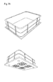
- non-magnetizable parts are to be held, they are to be provided with a magnetizable anchor plate of appropriate thickness. Due to the multi-coil arrangements with corresponding magnetic pole number almost constant adhesive forces can be generated over large areas, as used for example in machine tending tables. This will be in Fig. 16 illustrated.
- the stator of all polyphasic machines consists of a succession of individual teeth, each of which generally carries a concentrated tooth coil.
- the relationship between coil, winding axis and counting direction of the current is through the FIG. 17 described. It also shows the symbolic shortening for the following representations.
- the adjacent individual coils may belong to the same surface element or another surface element. Because of the required symmetry and the min. Three-stranded, the number of teeth and coils must be divisible by 3 without rest. Furthermore, the uniform distribution of the surface elements must be present.
- the frequency of the stator sizes is determined exclusively by the speed and the number z pm of the permanent magnets of the armature / rotor. In order to achieve a closed magnetic circuit without a unipolar flux, z pm must be an even number. In general, the coil width should be close to the pole pitch prevailing in the armature (possibly permanent magnets) in order to achieve a favorable winding factor ⁇ s .
- each tooth is wound so that the number of teeth and coils is identical.
- a particularly small winding overhang appears to result.
- the coil flux to be commutated is reduced; on the other hand, there is always an (inductance-increasing) negative feedback due to the two coil sides lying in a common groove.
- the design of the exciting coil, the use of suitable materials and the choice of the most favorable manufacturing technology have a great influence on the technical data of a DC magnet.
- the structure of the winding is the type of winding insulation and the arrangement of the coil within of the magnetic circuit of great importance for the specific working capacity of a DC magnet.
- Permanent magnet-excited linear motors are usually provided with a winding which lies completely in the air gap. Because of the then effective large magnetic gap is indeed to be expected with a reduced force density, on the other hand, a small stator inductance, extremely low force fluctuations and relatively small normal forces between the stator and translator achieved, the latter even completely disappear in a double-sided arrangement. This will be in Fig. 18 illustrated.
- aluminum is much lighter (30% of copper) than copper. For the required low voltage of a converter, a solution by aluminum windings is also acceptable.
- Another advantage of using aluminum is the rapidly forming insulating oxide layer. This not only makes the coil corrosion-resistant, but also replaces the otherwise usual insulation varnish. With decreasing wire diameter, however, care must be taken that the oxidation of the uppermost metal zone does not take up too much aluminum and inhibits the conductivity of the actual wire.
- Aluminum is also a relatively soft, tough and easily fusible metal and can also be processed well in converter production. Since the use of the coils is static in nature, the brittleness of aluminum is important only in production.
- thermo conductivity copper 401 W / (m ⁇ K)
- thermal conductivity aluminum 237 W / (m ⁇ K)
- the "short" and “low” Bestromungsfrequenz the coils allows a reduction of politiciansableitproblematik in most cases of application.
- the encapsulation contributes significantly to the heat dissipation. Nevertheless, the potential should Expansion of the materials used in heating be considered.
- stator poles Because of the constantly changing magnetization in the stator poles and in the stator yoke / axis, eddy current losses occur when solid iron is used in these parts. In conventional machines, therefore, the parts in which alternating fields or rotating fields occur are built up from layered iron sheets. In the surface elements, this approach may prove problematic because the geometry and the field pattern in the stator poles does not allow sheeting. Instead, the stator poles, the stator and the rotor yoke may be made of a soft magnetic powder composite material. This material consists of iron particles with an insulating surface, which are pressed under pressure and temperature to produce semi-finished products that can be processed conventionally. The disadvantage of this method is the compression stiffness and the load capacity of the blanks produced.
- SMC Soft Magnetic Composite
- It is an iron powder coated with a plastic layer that is given its final shape using conventional pressing technology followed by a sintering process.
- the magnetic and mechanical properties of the SMC material can be matched to requirements by adding powder in the powder, with appropriate adaptation of the sintering process. Achievable, for example, are a relative magnetic permeability of up to 700 and a saturation flux density of 2.0 T in a mechanical Strength of 100 N / mm 2 .
- complex isotropic structures can be produced, thus achieving a higher functional integration density.
- the surface element / surface engine (see Fig. 20 ) or the "electromagnetic tile” interacts with the integrated transducers / coils as a module element together with other surface elements combinatorially in the platform.
- Fig. 21 shows greatly simplified a possible construction of a surface element, wherein (not as in the concrete construction), the transducers represented by separate Statorpolfchipe and square pole heads and the electronic rules was very roughly simplified.
- the bottom of the surface element serves both the attachment of the surface element in the form of a holder or a plug-in system, as well as the fixation of the transducer. Furthermore, the bottom significantly contributes to the stability of the module, since the transducers are not directly connected to each other.
- an internal control element is switched between to regulate the corresponding transfer.
- the internal control element or the internal circuit controls the energy output in terms of strength, voltage and frequency with the aid of an integrated chip and the specified data of the external central platform controller.
- the magnetic field characteristic can thus be predetermined and influenced by the user via this control.
- control element controls the energy and data transfer of neighboring consumers and the central platform control. Data about and from detected objects that are on the surface element are processed and passed on to the corresponding user. Furthermore, the chip contains a unique identification number, which designates the respective surface element in its task, design, position, etc.
- the power supply of the respective converter is realized via a line network, which is located below or between the transducers. However, this must not influence potential magnetic fields or the stability of the surface element.
- interfaces are the most practical. These should be arranged such that incorrect connection of two supply lines is not possible if a neighboring tile is misplaced. Small vibrations, displacements and small gaps between the surface elements must also be able to be compensated via the interfaces. Interlocking fixed connectors have a high connection strength, but are usually relatively space-consuming and costly in their installation. In addition, they would have to have adequate insulation to be able to forward electrical power to any external users.
- the configuration of the contacts can be based on conventional contact connections, connectors and / or sliding contacts.
- a resilient contact solution which can be lowered into the surface element and terminates flush with the side surface of the surface element in the pressed-in state is preferred.
- the surface of this spring-loaded contact solution is curved to compensate for small displacements of two adjacent surface elements and thus to maintain the electrical energy and data supply.
- the location of the contacts on one side of the surface element is arranged so that when an incorrectly attached a wrongly attached alignment of a surface element to another surface element a connection between the contacts of the two surface elements is not possible.
- Each transducer is made of non-ferromagnetic filler material (in the Fig. 21 not shown) enclosed. This also serves as a filler for missing elements in a surface element, as well as the heat dissipation, the coefficient of thermal expansion and the improvement of mechanical strength and protection against aggressive media and pollutants. This can be done in appropriate forms or directly in the outer magnet body, for example, by encapsulation or encapsulation, whereby the air gaps between coil and iron circle are reduced or completely filled.
- the surfaces serve as a protective shell and for heat dissipation. They should be substantially flat in order to keep air gaps between the adjacent electromagnetic tiles and the support surface (bottom) low. The uniformity of the surface also allows an undisturbed movement of transport devices on the platform.
- the edges of the shell or the surface element should be made of the predominantly used non-magnetizable material aluminum in order to reduce costs and to provide a simpler recyclability.
- the surface element Due to the design of the transducers (teeth) and the slot slots, the surface element has an influence on the behavior of the transport devices.
- the dispersion of the currents in the grooves and the winding heads influences the inductance.
- the slot pitch and the design of the teeth also influence the cogging torque, the "torque ripple", the acceleration process and the braking action of the armature. Construction and gearing of a linear stepper motor and armature are in Fig. 22 shown.
- the shape is not limited to rectangular surface elements. Round shapes or polygons are conceivable. With uniform transducer elements, voids would be created in the same under the corresponding shaping of the surface element. Therefore, a modification of the normal matrix arrangement of the individual transducers in the tile is necessary or a shape adaptation of the structural size of the affected transducers. Further resulting gaps are filled with non-ferromagnetic material for stability reasons (encapsulation). This will be in Fig. 23 illustrated.
- Transport devices which want to change their position and position of horizontal surface elements of the platform in angled or vertically suspended portions require, depending on the design, corresponding transition elements.
- a simple solution provides three to a combined angular three-dimensional surface element.
- This shaping is achieved in that surface elements and / or transducers are arranged at different degrees to each other.
- the crevices caused by the Verwinklung be filled by non-ferromagnetic material.
- the connection between the surface elements and is achieved by electrical lines or contact composites, which are located in the resulting gap.
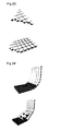
- this acts to build shaped magnetic fields, which thus exert a pull on ferromagnetic objects and guide them from a horizontal position to an angled position (see FIG Fig. 24 ).
- FIG Fig. 24 three-dimensional rounded shape variants of the surface element are also conceivable (as in FIG Fig. 24 shown).
- This shaping is achieved in that the transducers are arranged at different degrees to each other. The head parts of the transducers are moved closer to the head parts of the adjacent transducers than the stator foot elements.
- This shaping allows connecting surface elements between horizontal surface elements and vertically suspended surface elements. When activating the transducers, this leads to the formation of shaped magnetic fields, which thus achieve a more uniform motion on ferromagnetic objects from a horizontal position to an angled position.
- an almost arbitrary three-dimensional surface structure can be achieved by appropriately modified shaping of the surface elements.
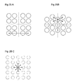
- An extension of the surface motor represents the realization of a third degree of freedom in the form of a rotation of the rotor / armature. So that forces can be generated in any position with twisted rotor in each position in x- and y-direction, new Statorpolan extract must be developed for this application (see Fig. 25 A, B and C. ), since the multipolar base assembly may possibly produce no more forces at a rotation of 45 ° in some positions. It must be checked whether the cogging forces and the cogging moments of these arrangements allow a meaningful operation.
- the structure of the platform must be subject to a certain energy network topology or data network topology with corresponding interface elements. However, this should be done in terms of the best possible integration into other networks and taking into account potential users and consumers.
- the page sizes of the surface elements are selected such that different types of sizes can be combined with one another and designed to yield a surface or platform adapted to the architecture. This will be in Fig. 28 illustrated.
- symmetrical recesses for the fixation of the surface elements by screw connections to the substrate and the adjacent surface elements are realized at an identical distance. They support the combinatorics of the individual surface types as well as the respective aspect ratios.
- the recesses are also used as a contact interface for the transfer of power and data to adjacent area elements and external users.
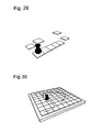
- FIGS. 29 and 30 Further area motors are in FIGS. 29 and 30 illustrated.
- the stator plate acts in this embodiment as a connecting and stiffening element of the entire surface element and at the same time as Statorfuß each coil. It consists of a cast iron or an alternative material.
- the axles / stator yokes protrude from the base plate for the windings of the bobbins. In addition to pole heads and coils, they also fix the electronic components. Furthermore, they catch all perpendicular forces acting on the surface element by eg transport devices.
- braces give the construction extra rigidity and stabilize the individual axles. Furthermore, they provide additional material for the circuit of magnetic field induction between the respective excited coils. Centered centrally from the respective squares of the checkerboard structure, a ring structure grows. It contributes to the fixation of the surface elements on the substrate and adjacent surface elements. In order to achieve a uniform efficiency of the coils and to keep eddy currents similar ring elements without special mechanical purpose are embedded in the stator plate. Details of the mode of operation are given in more detail in the section Interfaces and fixation.
- the board acts as a support plate for the electronic components of the surface element.
- the holes and recesses are positioned so that the board can be hung on the axes of the stator plate. Fix the hard rubber rings underneath and on the drill holes, catch finely vibrated vibrations and raise the electrical system to the optimum height generated heat fields of the coils are attenuated. This will be in Fig. 32 shown.
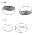
- Coils are prefabricated accurately before the attachment is made on the axes of the stator plate above the board. They consist of enameled copper wire or preferably aluminum enameled wire (see Figures 34A and 34B ).
- a round bobbin format is preferred.
- the winding is carried out from below along the stator axis and then back down over the first winding. It stretches from the inside out a winding over the previous one. This results in a wire beginning in the middle at the bottom of the coil.
- This wire beginning is reinforced with a contact element.
- the end of the wire emerges from the side edge (in the illustration at the top of the page) of the spool.
- the wire end is also reinforced with a contact element.
- the wire is already cast during the winding process with two non-conductive materials.
- the upper potting material dissipates the heat to the surface of the surface element to the outside.
- the lower Potting material at the base of the coil insulates the resulting heat towards the surface element interior.
- the wire ends and thus the connected contacts are also fixed by the potting.
- the coil contacts engage in correspondingly designed contact bores of the circuit board and are divided into the control electronics of the planar element. This will be in Fig. 35 illustrated.
- All coils are placed on the stator axes of the stator plate (as in Fig. 36 shown).
- the structure is symmetrical and kept the same in all surface elements in order to keep eddy current deviations low, to guarantee the combinatorics and to optimally implement the harmonized regulation of the coils.
- the number and the diameter of the coils result from the width of the surface element and the set contact / interfaces on the sides and in the inner region of the surface element.
- the coil diameter of the coils in all surface element types is the same, half, twice as large, etc. - so that the symmetry and function between all surface element types is maintained.
- the height of a coil may vary in the various surface elements.
- the voids take on contact / interfaces of the surface element and thus enable the energy and data exchange of the surface elements with each other or with external devices.
- the open spaces serve also as a recess for the fixation of the surface elements on the ground and with each other.
- the coil can be printed in horizontal slices. These disc coils are laid over one another, layered with insulating material / insulating varnish or printed in a 3D process.
- stator of a coil is divided in the case of the surface elements into the stator foot (the stator plate) with the stator axis and the stator head.
- the stator poles are separated. This is advantageous in production and repairs since individual elements (e.g., circuit board, coils, ...) can simply be plugged / removed and fixed to the stator plate.
- the (octagonal) pole heads are inserted with their centered pin into a precisely fitting hole of the corresponding stator axis (as in Fig. 37 shown). Alternatively, they can also be screwed in by means of a thread of the Polkopf://es and Statorplattenachsbohrung.
- the plug method in turn requires a high accuracy of fit of Polkopf://es and Statorplattenachsbohrung.
- a fixation of the pole head by, for example, gluing, stretching processes (freezing of the components during production.)
- the slightly wider pole pin expands again and presses into the stator plate bore.) or compression would, however, be a simple element replacement or reduced production not possible.
- recesses for such devices are located on the sides and in the interior of the surface elements.
- the task of the fixation device is to contract the surface elements - to combine them - as well as to connect them firmly to the substrate at the same time. This can be achieved by means of protruding out of the stator in the recesses ring elements on which in turn can be plugged / screwed a perfect fit fixing ring. About the ring elements of both surface elements, these are contracted and pressed precisely to each other. There is a fixation and exact combination of both surface elements. This will be in the FIGS. 39 and 40 illustrated.
- the fixation ring is surrounded by a non-conductive protective layer (plastic, rubber) on the surface.
- a non-conductive protective layer plastic, rubber
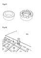
- fixation ring There are currently two types of fixation ring conceivable: A plug-in and a screw-fixation ring (see Fig. 41 ).
- the pluggable fixing ring is cheaper to produce in production and more stable in construction. However, he must use the insulating layer with, for example, a screwdriver or be levered out by a Verwinklung the surface elements against each other from the inner Statorplattenring.
- the screwed-on fixation ring has a thread on the inside which presupposes a precisely fitting thread on the outsides of the stator plate rings.
- this fixing ring can be screwed onto the rings of the stator. This is advantageous because a screwing and unscrewing of the ring and consequently a slight change of rings and surface elements is possible.
- a disadvantage is the complex creation of the precise thread of Statorplattenringe in production which must be exactly in the thread of the fixing rings.
- stator plates In addition to the fixation of the surface elements of the fixing realized by the combination of stator plates also a way to transmit the eddy currents of excited coils via a surface element on the adjacent surface element and to achieve in the way an indirect unit of the coil action for the entire platform.
- the platform acts as a uniform surface element.
- an ordinary screw is passed through the inner ring (the stator plate) and screwed to the ground.
- the screw head presses the fixing ring onto the stator plate ring against the stator plate and at the same time screws the stator plate or the surface element to the substrate. This will be in Fig. 42 shown.
- a screw with attached / compressed (isolated on the sides) fixing ring conceivable to allow a faster construction of the platform.
- an insulating closure at the head of the recess and an insulating washer on the screw is formed a stripped cavity, which shields the contacts of the surface element from external influences such as moisture and weather and protects against corrosion.
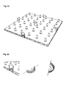
- the cut or contact points are symmetrical in the corresponding recesses of the surface elements. They exchange data and power between adjacent area elements and external beneficiaries / devices. This will be in Fig. 43 illustrated.
- the semicircular, and round tubular contact points are glued or welded to the shell / housing of the surface elements. However, they can also be an integral part of the housing and be slipped together on the components of the surface element during production. In addition, they may be soldered to the board and glued and thus integrated into the electrical system of the tile.
- the contact points are placed on the stator plate on the corresponding stator plate rings. This will be in Fig. 44 illustrated.
- the round or semi-circular contact point consists of insulation material and a rounding adapted contact material (copper, solder, ).
- the shape of the contact structure is provided with recesses such that it receives the contact lines flush.
- the individual contact lines run separately from each other in the interior of the round / half round stacked.
- the conductor paths run vertically embedded in the surface. This will be in Fig. 45 shown.
- Layer by layer passages are provided in the construction for the respective contact lines, which the individual lines of the inner round with the corresponding vertical Connect the conductor tracks of the outer circle.
- the lines of the inner circular run in such a way that they are not in direct contact with contact points of the next docked surface element. Only a suitably designed positioned fixing ring or a contact element in the recess establishes a connection. This physical separation of the lines from surface element to surface element enables a user-desired mechanical activity control of a surface element. Software errors, control errors, incorrect contacts or unwanted electrical connections can be prevented in this way. Only surface elements which are interconnected by a contact device can exchange power and data.
- the contact fixation rings are similar to the already presented Fixierringen. They are also plugged / screwed onto the stator plate ring and force the adjacent surface elements together. Their outer rounding is also provided with an insulating layer. In this insulating layer annular electrical conductor paths are embedded at the corresponding height to the contact layers of the contact points of a surface element. These pathways each receive a contact ring, which establishes the electrical connection via the contact points of the adjacent surface elements to the same.
- the recessed contact rings have a slightly larger radius than Merfixierringe and the contact points. They are interrupted at one point.
- the contact fixing rings or fixing rings can have an inner degree.
- a screw head which projects beyond the screw thread by the larger radius rests on this degree.
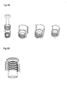
- the screw head thus also presses the contact fixing ring or fixing ring onto the corresponding ring element of the stator plate. This also guarantees the fixation of the contact rings ( Fig. 48 ) at the correct height to the contact points and contact lines of the surface elements.
- the respective contact points should also be available for external users / devices as data as well as energy interface. This allows a power supply of external devices and / or a data exchange through a contact adapter (see 51 ).
- contact adapter can be sunk or screwed into the recesses and contact points of the surface elements.
- contact adapters range in size to the surface element surface and fill in the head (possibly flush or overhanging) the degree in the recess. About a slot on the head of the contact adapter, the same can be screwed into the recess of the surface element and tightened. Since it is not always desired to screw the surface element to the substrate, there are two types of contact adapters: contact adapters with internal threads which screw over the stator plate rings and contact adapters with a protruding screw thread which also fix the surface elements to the substrate. This will be in Fig. 52 illustrated.
- a contact adapter internal device and wiring carries the appropriate power and / or the corresponding data to the respective area of the plugged plug.
- a concrete internal structure of a contact adapter for receiving various plug devices has not yet been developed; is expected to comply with the given standards and norms.
- the surrounding coils are in the deactivated state. This protects the infected device, does not cause magnetic field irritation, and the excited magnetic vortex currents can not affect the functions of the external beneficiary (see Fig. 53 ).
- the power and data exchange from external devices / beneficiaries via the surface elements of the platform with the central control system allows a wider range of applications.
- Such introduced sensor technology whether optical or inductive, would also support the location of overlying objects.
- Special devices for contactless energy and data transmission are conceivable (if not realized by the coils of the surface element).
- External beneficiaries can be influenced in their behavior and their energy / data supply.
- Individual shutdowns by the central control system are possible at any time, an exact power and data monitoring are possible. Further, data input by external devices into the system increases the power of both the external device and the central system.
- the envelope of a surface element consists of non-conductive non-ferromagnetic material. Preferably plastic. It consists of several components: the bottom plate of the casing, the sides of the casing and the casing roof / casing cover.
- the bottom plate of the shell adapts its shape to the basic shape of the stator plate, with which it is glued or potted. It has on the sides and inside corresponding recesses and holes for the fixations and contact points of the surface element (see FIGS. 55 and 56 ).
- the shell sides / side walls also conform to the shape of the stator plate. They are symmetrical.
- the stator plate "penetrates" the foot of the sidewalls around with the adjacent surface element directly in To get in touch. In this way, another interface is created for eddy currents between energized coils of adjacent surface elements.
- each side wall In the middle of each side wall is also one or larger area elements a plurality of recesses in the form of a continuous gap for the fixings and contact points of the surface element.
- vertical stabilizing struts which are based on the number and the ring diameter of the stator plate rings and insert into this. This type of gearing of shell and interior components fixed and reinforced.
- the hull roof / hull cover (see Fig. 58 ) is provided in addition to the recesses for the fixing points and contact points with recesses for the pole heads of the converter.
- the material is particularly heat-conducting to the heat radiation, which forms in the interior of the tile temporarily by the energized coil to dissipate to the outside.
- edges were composed of edge elements of different lengths / edge types, which were designed for the accuracy of fit and size of the various surface elements.
- the edge elements exist with lengths of 25cm, 50cm, 100cm.
- the structure and structure of the respective edge types may additionally vary.
- edge types with straight edges / profile should be used.
- a beveled edge profile makes sense. If e.g. Devices must be driven or rolled onto the platform.
- All boundary elements are separately screwed to the ground.
- a fixing of the edge elements to a slot of the edge elements can be realized.
- corresponding nuts are inserted laterally into the recess / slot of the edge element. Screws which are screwed through holes in the ground with these inserted nuts fix the edges in this way from the back / bottom of the platform with the ground.
- Fig. 67 shows a frame element slope (25cm) with two screw recesses and a surface fixation site
- edges were aligned with the market-standard products of the company "item” in order to achieve the greatest possible compatibility with standardized and widespread designs.
- the integration potential of the surface elements is to be increased and already common products can be integrated into the platform.
- the size and history of parts of the inner braces is purposely modeled on "item” products for passport and compatibility reasons.
- the exterior dimensions fit However, the structure of the platform / surface elements.
- the edge elements are provided with cavities. Internal braces absorb compressions due to external influences and increase the overall stability or rigidity of the edge elements. This also makes it easier to produce.
- the hot soft material of the edge element is drawn longitudinally during manufacture and retains the drawn shape during the cooling process.
- the pointed edge was deburred. This serves on the one hand a certain dirt brake as well as for the reinforcement of the element material.
- the blunt tip / edge is no longer so easy to damage.
- the frame corners are designed to fit perfectly to the edge elements. Like other frame elements, they have a screw hole for fixing to the ground by means of a screw. This threaded hole also has a degree for the countersink of BlendknÜn. Furthermore, slots for screwing with other devices in the frame corner element are also embedded on the bottom (see Fig. 68 ).
- the slots, holes and recesses in the frame elements can also be provided with plug-in connections to insert or attach other frame members or other devices.
- a recessed wiring in the frame elements is conceivable.
- the central control system would not be connected directly to a surface element of the platform, but to a dedicated interface frame element. This then realized by means of the contact interfaces of the surface elements, the energy and data transfer between the platform and the central control system. Where external Beneficiaries can also benefit from this wiring.
- the existing interfaces to the surface elements should be used. However, an additional power and data interface attached to a frame element should not be ruled out.
- the individual surface elements which are individually assembled by the user into a platform, receive from a central computer the corresponding control signals in order to specifically excite magnetic fields and to condition the energy of other beneficiaries.
- the required energy can also be supplied to the system centrally.
- the software controls the individual values of the electric coils through the protocol by means of a data bus via the respective interfaces of the surface elements.
- a serial bus system USB, Firewire.
- This internal circuit was designed to control power, voltage and frequency energy dissipation with the help of an integrated uniquely assignable shift register, controller, etc. and the default external platform control data.
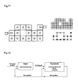
- FIG. 71 shows an exemplary networking of surface elements.
- a neural structuring with a certain "intelligence" of each surface element can be selected.
- the neural solution can be disadvantageous in the event of disturbances occurring during the movement sequence of a transport device with regard to the route optimization of all transport devices.
- a neural structure makes possible a certain independence of the surface elements from the central control, which in turn reduces disturbances of the data transmission by the center, and the timely, smooth data transfer with adjacent surface elements.
- the structure of the network topology for the power supply is also to be optimized according to consumption and cost-effectiveness and is based on the specifications of the electromagnetic coils, the electronic elements, as well as the needs of potentially connected non-system users.
- the maximum number of combinable surface elements of a platform thus also results from the economically optimized and justifiable specifications of the electrical and mechanical individual components of the control.
- Fig. 72 roughly shows the structure of a shelving system.
- the electromagnets in the surface elements represent their own drive system and are not, as usual, elements in higher-level drive systems. This property can be resource efficient on potential transporters / anchors.
- Anchors in transport devices which transport objects, can be designed differently in order to ensure the best possible variety of movements, taking into account the mass moment of inertia. Nevertheless, production becomes technical Reasons a standardized anchor type which attaches to different transport devices / fix favors.
- a possible embodiment of a passive transport device in the lateral sectional view is indicated.
- Their supporting rolling elements sit on a fixed surface element.
- Above the rollers / wheels is the actual transport surface on which the objects to be transported are located or fastened.
- the body sits between the rollers and under the transport surface. It contains ferromagnetic elements or permanent magnets, which are mounted as anchors in the relatively close proximity of the surface element.
- the rollers to reduce magnetic vortex be arranged at a certain distance next to each other.
- the rollers can be interspersed with ferromagnetic elements or permanent magnets. If the transducers of the surface element build up electromagnetic fields, they act on the areas of the transport device equipped with ferromagnetic elements.
- the anchor elements are pulled to the electromagnetic tile. This causes the right one Design of the magnetic fields, a movement of the transport device.
- the transport device is pulled tangentially by magnetically guiding waves (see Fig. 74 ).
- Transport devices may themselves contain controllable surface elements or transducers and, analogously to the surface elements, generate electromagnetic forces for proper movement in conjunction with external ferromagnetic elements. However, this is expensive and not the preferred variant.
- An optimized arrangement and material selection (ferromagnetic elements, permanent magnets, ...) of the anchor elements in the transport device can support the magnetic force effects of the surface elements. If the anchor element is offset from the pole of the converter in the planar element, the magnetic force of the excited pole and thus the armature can be shifted by half the transducer width so that the transducer and the active element are exactly opposite each other. Now, if the excitation coil of this converter is turned off and another converter turned on, the anchor element is slightly offset above it, so will flow through this pole of the magnet, the maximum flux and pull the anchor exactly on this. There is a shift. Following activation of the first transducer and deactivation of the second transducer, tangential forces are generated in this way. With continuous repetition of this control a rotor movement of the armature object is achieved. This will be in Fig. 77 illustrated.
- the vectorial superimposition of the stator field with the field of the permanent magnets can form a "magnetic tooth structure" which generates an additional force component and thus contributes to the "torque” of the machine.
- An increase in magnet volume leads to an increase in the mechanical load of the webs in the transort devices, which hold the respective magnet and the associated piece of sheet metal between the magnet and the air gap. It is therefore necessary to optimize the parameters of height and width of the magnet (pole coverage).
- the limit for the max. mean stress in the webs should not be too high considering the notch effects and take into account the number of expected load cycles. Analytical calculations of the occurring stresses should be checked by finite element calculations. This is done by calculating Maxwell's stress tensor (area force density) or by using the energy conservation law (principle of virtual displacement, change of magnetic energy).
- Fig. 79 shows four stator modules / surface motors with a large-area armature.
- transport devices or beneficiaries can use the form of contactless electrical energy supply and bidirectional electrical data transmission via the surface elements for their electrical energy supply and electrical data supply. This is achieved via a coil / converter circuit in the medium frequency range, if the overall system has corresponding power electronic components on the side of the power supply and on the load side.
- the thus supplied energy and data can in turn be used for a separate, independent of the system, motion performance of this transport device.
- the platform would be capable of escorting passive, guiding character, supporting features and controlled propulsion devices.
- the contactless inductive energy transfer enables the supply of mobile consumers with electrical energy.
- the elimination of bus bars, tow cables or slip rings increases the mobility of consumers.
- Safety and reliability of the energy supply improve due to the absence of mechanical contacts.
- a contactless energy transfer is safer and maintenance-free due to the galvanic isolation.
- the avoidance of contact contact resistance and spark formation is advantageous, so that the technology is predestined for use in harsh environments.
- Core of the contactless transmission system is a transformer magnet arrangement. Unlike the classic transformer, however, there is no closed iron core. Rather, the primary and the secondary coil are separated by an air gap, which can be several decimeters in size. There the energy transfer takes place in the medium-frequency range, has the entire system on the side of the power supply and on the consumer side corresponding power electronic modules. The electric power that can be transmitted in this way ranges between a few mW and several kW. With targeted electrical and magnetic design, a good efficiency can be achieved even with large air gaps.
- data transmission is required in addition to the power supply. This may be desired in one direction or bidirectionally.
- the data transmission is also contactless inductively possible.
- transducers provided in the surface elements for contactless power and data transmission would allow for powering electrical devices above.
- a permanent exchange of data between the system and EDP-heavy consumers would be conceivable.
- the area element consequently also functions as an input interface.
- the goal is to generate a constant alternating current in a primary loop. This is achieved by the quadrupole in its function as voltage / current converter.
- the energy is removed by means of a pick-up, whose secondary winding is part of a resonant circuit.
- the magnetic field generates a current in the secondary winding which can be rectified as needed.
- the non-contact energy transfer requires a magnetic field of constant amplitude. This current source behavior allows the quadrupole, in which the current is kept constant, regardless of the load.
- the switching frequency of the inverter should be as high as possible to minimize the volume of the inductors (example: frequency of 20 kHz).
- the pick-up (see Fig. 81 ) represents the secondary winding of the transformer. It consists only of an inductance and a capacitance. Both elements form a resonant circuit. This resonant circuit can be designed as a series or as a parallel resonant circuit.
- the ferrite core of the coils concentrates the magnetic flux that is built up from the primary circuit.
- the output voltage of the pick-up is proportional to the number of turns and to the primary current, so that there is the possibility to adjust the voltage over this.
- the necessary positioning accuracy and automated detection of transport devices and obstacles requires sensors with high resolution and very high repeatability.
- the sensor must be immune to magnetic fields, shocks and vibrations.
- the coils should, if possible, be used to measure inductions and eddy currents, which are produced by active elements on the surface elements. If this is not possible due to technical control reasons, detection coils are embedded in the cover of the surface element envelope / of the surface element housing.
- Metal detectors / inductive proximity switches consist of an electronic circuit and a search coil through which low-frequency alternating current flows.
- the shape of the coil is either flat (plate or ring shape, without core) or stretched (cylindrical coil).
- the flat shapes are used to scan people or floor areas, while the elongated shapes are used to locate the course of pipes and cables in the earth and in walls. This will be in Fig. 82 (Example, not part of the claimed invention).
- Metal detectors are subdivided according to the underlying measurement methods pulse measurement and alternating current measurement:
- pulse measurement and alternating current measurement In the former, individual current pulses are transmitted periodically via the transmitting coil. These pulses generate eddy currents in metallic objects in the vicinity of the coil. These in turn cause a signal change in the receiver coil which can be measured as voltage immediately after switching off the transmitter pulse.
- the signal evaluation is usually done in the time domain.
- a mostly low-frequency alternating current signal is continuously transmitted, which in turn is analyzed as a received signal in the receiving coil.
- the transmission principle is a magnetically coupled system similar to a transformer.
- the transducers of the surface elements are to be used as detectors by the pulse measurement method (see Fig. 83 . 84 ).
- the transducers thus act as transmitting and receiving coils. This would allow an analysis of the location and shape of ferromagnetic elements located above and thus incorporate transport connections into the system accordingly.
- passive objects with ferromagnetic properties are to be integrated automatically into the data set of the system in this way.
- the operating system would adapt the travel routes of the transport devices around these objects.
- a holistic scan through all coils at any time is not necessary. Temporarily frequented and selected detections by isolated coils are sufficient for a rough overview of the goods which are located on the platform. With increased object volume and traffic, the frequency and accuracy (ie the number of addressed coils) of the measurements around these ranges are also increased. This allows for an economical use of the system at any time an optimal overview of the objects located on the platform.
- detection coils are no longer meaningful for each pole of a transducer. Instead, the coils are guided in rectangular tracks around each row of pole heads / transducers (see Fig. 85 ).
- the tracks of the detection coils run side by side in the x-direction and side by side in the y-direction. It creates 2 web surfaces which overlap.
- the line starts and ends run from the bobbin over the shell walls to the board in the appropriate control technology. This allows a reduction of cable carriers and electronic assemblies.
- Surface elements are combinatorial sub-elements of a designed platform. In order to be able to work optimally in combination with the control by the central control system, it requires a unique identification feature. With the aid of this identification feature, the central system control can read out the type and design as well as disturbances of the electromagnetic tile / surface elements and react accordingly to these data. With the feature determination, not only are all the tile capabilities, such as the type, arrangement and design of the transducer or the shape and size of the surface element itself, broken down, but it is determined by reference of adjacent surface elements, the exact location and position. This unique identifier is identified by an identification number (IB, see Fig. 88 ) realized.
- IB identification number
- This IB (Identification Number) is easily transferable from tile to tile, similar to a phone number or computer MAC address, and can be read by the controller in this way. It is vaccinated and fired in the microcontroller of each surface element. Thus, the IB is connected indefinitely to the surface element.
- the uniqueness of the IB also provides an effective protection mechanism against theft or piracy. Unregistered IB and tile elements are recognized by the operating system and excluded from operation. Should the local network continue to be connected to neighboring networks, it is also possible to automatically report stolen or copied elements to the next provider or central contracting authority.
- the ownership is still easy to determine. Although this is not the case for fixed surface elements in one place This is absolutely necessary, but if the IB system is also implemented in transport devices or objects (eg with the help of an RFID tag), the benefits are quickly revealed. Similar to a chassis number of an automobile or a watermark, ownership of the transport device can be easily understood here as well. This is extremely useful in the daily exchange of objects, goods and goods. Especially since the system can thus track the respective location in real time and respond to the user's wishes accordingly.
- This control should be able to receive, evaluate and forward data in cooperation with all network participants, as well as to intervene in a controlling and regulatory manner.
- the proposed device has three software areas (see Fig. 89 ).
- the next software hardware works in the microcontrollers or the direct circuit in the surface elements. Together with the IB number, the relevant data, such as object detections, faults or converter drive commands, are exchanged with the operating system.
- the operating system acts as an interface between hardware and application software.
- the operating system will serve as an interface between the surface elements of the platform and the application software.
- the operating system issues control commands for converter control to the circuit and the microcontroller of the corresponding surface elements.
- Which surface elements and which transducers are addressed is decided by the operating system on the basis of the tile identification numbers (IB) available to it.
- the respective IBs provide the operating system with the exact tile type and tile location in the overall structure of the platform. In this way, every transducer and every function in the surface elements can be addressed. This also applies to the electrical power transfer and signal transfer from surface element to surface element or to another beneficiary.
- appropriately designed transport devices or electrical devices located on the platform can use the contactless energy or signal transmission. Every consumer can be addressed or electrically isolated. Failures and malfunctions are also registered and forwarded to the user software. In the worst case, emergency measures, such as a stop of all moving transport devices, are initiated.
- the operating system coordinates the exchange of data from foreign networks and systems similar to a switch or router.
- an internet connection can be made via the platform from the laptop to the connected telephone network through a plug-in connection in the area elements. This allows the control of electrical devices with the platform as a transmission medium.
- the operating system manages the detection of detectable objects on the platform.
- the corresponding coils and surface elements are interrogated temporarily and the recognized objects are perceived in their design and speed.
- the collision control and management of the movements or routes of transport units also falls in some areas to the operating system, so that the user software can be relieved.
- the system of the Japanese Railways serves as a model.
- the Japanese Railways will decide on the optimal version for restoring the overall system.
- the highest parameter here is the degree of dissatisfaction of the passengers.
- the system should similarly deal with the allocation of benefits over other target competing transport units on the platform.
- the operating system receives information about the respective objects from the transport units themselves or from the user software via the user software. Routes and priorities are re-calculated in the form of a flexible real-time timetable. The priorities to be assigned are based on criteria such as safety, hazardous substances, object type, object shape, temperature-dependent objects, food, transported living beings, etc.
- the maximum speeds, acceleration speeds and deceleration speeds of the transport units also play an important role in the moving interaction in addition to the priority behavior.
- Statistical probabilities of the retrieved transport units at specific locations at certain times have a predictive influence on the individual storage and behavior of the transport units controlled by the overall system. This increases the availability and the smooth running. simultaneously It reduces transport area buffers and thus contributes to the economic approach of the overall system.
- Planning, control and controlling tools optimize the intended material flow and the corresponding energy output to transport devices or external users.
- the route calculation of the operating system for transport devices can be influenced. Paths, positions, behaviors of driven objects can be determined in the same way by the user in their scope or in their activation time.
Landscapes
- Engineering & Computer Science (AREA)
- Physics & Mathematics (AREA)
- Chemical & Material Sciences (AREA)
- Combustion & Propulsion (AREA)
- Electromagnetism (AREA)
- Power Engineering (AREA)
- Transportation (AREA)
- Mechanical Engineering (AREA)
- Linear Motors (AREA)
- Non-Mechanical Conveyors (AREA)
- Toys (AREA)
Claims (5)
- Système de stockage ou de transporta) avec un moteur planaire électromagnétique (1, 1') qui entraîne un dispositif de transport (10, 16) ;b) le moteur planaire (1, 1') comportant plusieurs convertisseurs actifs (2) qui peuvent produire des champs magnétiques appropriés (7) pour exercer une force sur le dispositif de transport (10, 16) ;c) le dispositif de transport (10, 16) étant monté sur des roues (11) ou des rouleaux ; etd) le dispositif de transport (10, 16) étant conçu de manière passive pour ce qui est de l'entraînement par le moteur planaire (1, 1') ;
caractérisé en ce quee) au moins un dispositif pour la détection de métal est intégré dans le moteur planaire ; et en ce quef) le ou les dispositifs pour la détection de métal sont conçus comme des détecteurs de proximité inductifs, sachant que- comme détecteur, soit les convertisseurs fonctionnent comme émetteurs et bobines réceptrices dans le procédé de mesure d'impulsions,- soit des bobines de détection individuelles, construites rectangulaires, sont prévues autour ou au-dessus de chaque tête polaire individuelle d'un convertisseur,- soit des bobines de détection sont guidées dans des trajectoires rectangulaires à chaque fois autour d'une série de têtes polaires des convertisseurs. - Système de stockage ou de transport selon la revendication précédente, caractérisé en ce que le dispositif de transport (10, 16) comporte un induit qui contient un matériau ferromagnétique.
- Système de stockage ou de transport selon l'une des revendications précédentes, caractérisé en ce que les convertisseurs (2) sont conçus de telle sorte qu'ils peuvent transmettre de l'énergie ou des données sans contact au dispositif de transport (10, 16) ou à un autre convertisseur (2).
- Système de stockage ou de transport selon l'une des revendications précédentes, caractérisé en ce que les convertisseurs (2) comportent des contacts ou des interfaces pour des connexions à fiches en vue de la transmission d'énergie ou de données ou en vue de la fixation d'éléments externes et/ou de dispositifs externes.
- Système de stockage ou de transport selon l'une des revendications précédentes, caractérisé en ce que le moteur planaire (1, 1') constitue une forme de surface tridimensionnelle avec laquelle un dispositif de transport (10, 16) peut être déplacé dans trois dimensions.
Priority Applications (1)
| Application Number | Priority Date | Filing Date | Title |
|---|---|---|---|
| PL08758955T PL2165406T3 (pl) | 2007-06-02 | 2008-06-02 | System magazynowy lub transportowy |
Applications Claiming Priority (2)
| Application Number | Priority Date | Filing Date | Title |
|---|---|---|---|
| DE102007025822A DE102007025822A1 (de) | 2007-06-02 | 2007-06-02 | Kombinierbares Flächenelement mit einer Vielzahl von ansteuerbaren Wandlerelementen |
| PCT/EP2008/004387 WO2008148513A1 (fr) | 2007-06-02 | 2008-06-02 | Système de stockage ou de transport |
Publications (2)
| Publication Number | Publication Date |
|---|---|
| EP2165406A1 EP2165406A1 (fr) | 2010-03-24 |
| EP2165406B1 true EP2165406B1 (fr) | 2013-04-03 |
Family
ID=39790259
Family Applications (1)
| Application Number | Title | Priority Date | Filing Date |
|---|---|---|---|
| EP08758955A Active EP2165406B1 (fr) | 2007-06-02 | 2008-06-02 | Système de stockage ou de transport |
Country Status (12)
| Country | Link |
|---|---|
| US (1) | US8281888B2 (fr) |
| EP (1) | EP2165406B1 (fr) |
| JP (1) | JP5506667B2 (fr) |
| CN (1) | CN101779368B (fr) |
| AU (1) | AU2008258826B2 (fr) |
| CA (1) | CA2692956C (fr) |
| DE (1) | DE102007025822A1 (fr) |
| DK (1) | DK2165406T3 (fr) |
| ES (1) | ES2416429T3 (fr) |
| IL (1) | IL202398A (fr) |
| PL (1) | PL2165406T3 (fr) |
| WO (1) | WO2008148513A1 (fr) |
Cited By (3)
| Publication number | Priority date | Publication date | Assignee | Title |
|---|---|---|---|---|
| DE102017003120A1 (de) | 2017-03-30 | 2018-10-04 | Nils Dreifke | Planares Transportsystem und Verfahren zum gleichzeitigen, unabhängigen Handhaben von Objekten |
| DE102019117430A1 (de) * | 2019-06-27 | 2020-12-31 | Beckhoff Automation Gmbh | Verfahren zum Bewegen eines Läufers in einem Planarantriebssystem |
| EP4656564A1 (fr) * | 2024-05-31 | 2025-12-03 | ABB Schweiz AG | Navette hybride pour moteurs linéaires à stator plan et long |
Families Citing this family (99)
| Publication number | Priority date | Publication date | Assignee | Title |
|---|---|---|---|---|
| DE102010028769A1 (de) * | 2010-05-07 | 2011-11-10 | Pvt Probenverteiltechnik Gmbh | System zum Transportieren von Behältern zwischen unterschiedlichen Stationen und Behälterträger |
| EP2589966A1 (fr) * | 2011-11-04 | 2013-05-08 | Roche Diagnostics GmbH | Système de distribution d'échantillon de laboratoire et procédé correspondant de fonctionnement |
| EP2589968A1 (fr) * | 2011-11-04 | 2013-05-08 | Roche Diagnostics GmbH | Système de distribution d'échantillons de laboratoire, système de laboratoire et procédé de fonctionnement |
| EP2589967A1 (fr) * | 2011-11-04 | 2013-05-08 | Roche Diagnostics GmbH | Système de distribution d'échantillon de laboratoire et procédé correspondant de fonctionnement |
| US9518504B2 (en) * | 2011-11-17 | 2016-12-13 | Kawasaki Jukogyo Kabushiki Kaisha | Air intake structure of engine and motorcycle having the same |
| DE102012102971A1 (de) * | 2012-03-06 | 2013-09-12 | Rolf Strothmann | Anordnung aus einem Aktor und einem Aktorhalter |
| CN106329814B (zh) * | 2012-10-17 | 2019-01-25 | 上海交通大学 | 基于永磁体和电磁体相互作用的位移驱动装置 |
| DE102014202843B3 (de) | 2014-02-17 | 2014-11-06 | Roche Pvt Gmbh | Transportvorrichtung, Probenverteilungssystem und Laborautomatisierungssystem |
| DE102014202838B3 (de) | 2014-02-17 | 2014-11-06 | Roche Pvt Gmbh | Transportvorrichtung, Probenverteilungssystem und Laborautomatierungssystem |
| EP2927625A1 (fr) | 2014-03-31 | 2015-10-07 | Roche Diagniostics GmbH | Système de distribution d'échantillons et système d'automatisation de laboratoire |
| EP2927695B1 (fr) | 2014-03-31 | 2018-08-22 | Roche Diagniostics GmbH | Système de distribution d'échantillons et système d'automatisation de laboratoire |
| EP2927167B1 (fr) | 2014-03-31 | 2018-04-18 | F. Hoffmann-La Roche AG | Dispositif d'envoi, système de distribution d'échantillons et système d'automatisation de laboratoire |
| EP2927163B1 (fr) | 2014-03-31 | 2018-02-28 | Roche Diagnostics GmbH | Dispositif de transport vertical, système de distribution d'échantillons et système d'automatisation de laboratoire |
| EP2927168A1 (fr) | 2014-03-31 | 2015-10-07 | Roche Diagniostics GmbH | Dispositif de transport, système de distribution d'échantillons et système d'automatisation de laboratoire |
| EP2957914B1 (fr) | 2014-06-17 | 2018-01-03 | Roche Diagnostics GmbH | Système de distribution d'échantillons de laboratoire et système d'automatisation de laboratoire |
| EP2977766A1 (fr) | 2014-07-24 | 2016-01-27 | Roche Diagniostics GmbH | Système de distribution d'échantillons de laboratoire et système d'automatisation de laboratoire |
| EP2995580A1 (fr) | 2014-09-09 | 2016-03-16 | Roche Diagniostics GmbH | Système de distribution d'échantillons de laboratoire et système d'automatisation de laboratoire |
| EP2995960B1 (fr) | 2014-09-09 | 2020-07-15 | Roche Diagniostics GmbH | Système de distribution d'échantillons de laboratoire et procédé d'étalonnage de capteurs magnétiques |
| US9952242B2 (en) | 2014-09-12 | 2018-04-24 | Roche Diagnostics Operations, Inc. | Laboratory sample distribution system and laboratory automation system |
| EP2995958A1 (fr) | 2014-09-15 | 2016-03-16 | Roche Diagniostics GmbH | Procédé pour faire fonctionner un système de réseau de distribution d'échantillons de laboratoire, système de distribution d' échantillons de laboratoire et système d'automatisation de laboratoire |
| EP3006943B1 (fr) * | 2014-10-07 | 2020-04-22 | Roche Diagniostics GmbH | Module pour système de distribution d'échantillons de laboratoire, système de distribution d'échantillons et système d'automatisation de laboratoire |
| EP3016116A1 (fr) | 2014-11-03 | 2016-05-04 | Roche Diagniostics GmbH | Dispositif de carte de circuit imprimé, bobine pour système de distribution d'échantillons de laboratoire, système de distribution d'échantillons et système d'automatisation de laboratoire |
| DE102014116232B4 (de) * | 2014-11-07 | 2023-07-27 | Weber Maschinenbau Gmbh Breidenbach | Individueller Transport von Lebensmittelportionen |
| EP3070479B1 (fr) | 2015-03-16 | 2019-07-03 | Roche Diagniostics GmbH | Support de transport, système de distribution de marchandises de laboratoire et système d'automatisation de laboratoire |
| EP3537160B1 (fr) | 2015-03-23 | 2020-08-12 | Roche Diagnostics GmbH | Système de distribution d'échantillons de laboratoire et système d'automatisation de laboratoire |
| EP3095739A1 (fr) | 2015-05-22 | 2016-11-23 | Roche Diagniostics GmbH | Procédé de fonctionnement d'un système de distribution d'échantillons de laboratoire, système de distribution d'échantillons de laboratoire et système d'automatisation de laboratoire |
| EP3096145B1 (fr) | 2015-05-22 | 2019-09-04 | Roche Diagniostics GmbH | Procédé d'exploitation d'un système d'automatisation de laboratoire et système d'automatisation de laboratoire |
| EP3096146A1 (fr) * | 2015-05-22 | 2016-11-23 | Roche Diagniostics GmbH | Procédé de fonctionnement d'un système de distribution d'échantillons de laboratoire, système de distribution d'échantillons de laboratoire et système d'automatisation de laboratoire |
| DE102015209610A1 (de) | 2015-05-26 | 2016-12-01 | Robert Bosch Gmbh | Transportvorrichtung |
| DE102015210905A1 (de) | 2015-05-26 | 2016-12-01 | Robert Bosch Gmbh | Transportvorrichtung |
| EP3112874A1 (fr) | 2015-07-02 | 2017-01-04 | Roche Diagnostics GmbH | Module de stockage, procédé d'exploitation d'un système d'automatisation de laboratoire et système d'automatisation de laboratoire |
| EP3121603A1 (fr) | 2015-07-22 | 2017-01-25 | Roche Diagnostics GmbH | Support de récipient d'échantillon, système de distribution d'échantillons de laboratoire et système d'automatisation de laboratoire |
| DE112015006518A5 (de) * | 2015-08-11 | 2018-01-25 | Festo Ag & Co. Kg | Positioniersystem mit Magnetanordnung |
| EP3139175B1 (fr) | 2015-09-01 | 2021-12-15 | Roche Diagnostics GmbH | Système de distribution d'une cargaison de laboratoire, système d'automatisation de laboratoire et procédé de fonctionnement d'un système de distribution de cargaison de laboratoire |
| EP3153867B1 (fr) | 2015-10-06 | 2018-11-14 | Roche Diagniostics GmbH | Système d'automatisation de laboratoire, procédé associé et système de distribution d'échantillons de laboratoire |
| EP3153866A1 (fr) | 2015-10-06 | 2017-04-12 | Roche Diagnostics GmbH | Procédé de détermination d'une position de transfert intercellulaire et système d'automatisation de laboratoire |
| EP3156352B1 (fr) | 2015-10-13 | 2019-02-27 | Roche Diagniostics GmbH | Système de distribution d'échantillons de laboratoire et système d'automatisation de laboratoire |
| EP3156353B1 (fr) | 2015-10-14 | 2019-04-03 | Roche Diagniostics GmbH | Support de rotation d'un support de récipient d'échantillon, système de distribution d'échantillons de laboratoire et système d'automatisation de laboratoire |
| EP3211429A1 (fr) * | 2016-02-26 | 2017-08-30 | Roche Diagnostics GmbH | Dispositif de transport présentant une surface d'entraînement en mosaïque |
| EP3211430A1 (fr) * | 2016-02-26 | 2017-08-30 | Roche Diagnostics GmbH | Dispositif de transport de modules dotés d'une plaque de base |
| EP3211428A1 (fr) * | 2016-02-26 | 2017-08-30 | Roche Diagnostics GmbH | Unité de dispositif de transport pour un système de distribution d'échantillons de laboratoire |
| CN109196363A (zh) | 2016-06-03 | 2019-01-11 | 豪夫迈·罗氏有限公司 | 实验室样品分配系统和实验室自动化系统 |
| EP3255519B1 (fr) | 2016-06-09 | 2019-02-20 | Roche Diagniostics GmbH | Système de distribution d'échantillons de laboratoire et procédé d'exploitation d'un tel système |
| EP3260867A1 (fr) | 2016-06-21 | 2017-12-27 | Roche Diagnostics GmbH | Procédé de détermination d'une position de transfert et système d'automatisation de laboratoire |
| JP6752350B2 (ja) | 2016-08-04 | 2020-09-09 | エフ.ホフマン−ラ ロシュ アーゲーF. Hoffmann−La Roche Aktiengesellschaft | ラボラトリ試料分配システム及びラボラトリ自動化システム |
| US10464427B2 (en) * | 2016-08-29 | 2019-11-05 | Universal City Studios Llc | Systems and methods for braking or propelling a roaming vehicle |
| US9868053B1 (en) * | 2016-09-01 | 2018-01-16 | Tzu-Hsiang Tseng | Push device for mahjong tiles |
| US9707473B1 (en) * | 2016-09-01 | 2017-07-18 | Tzu-Hsiang Tseng | Stacking device for mahjong tiles |
| CA3035965C (fr) | 2016-09-09 | 2022-01-11 | The Procter & Gamble Company | Systeme et procede de remplissage simultane de recipients avec differentes compositions fluides |
| EP3509953A1 (fr) | 2016-09-09 | 2019-07-17 | The Procter and Gamble Company | Système et procédé de remplissage simultané de récipients de formes et/ou de tailles différentes |
| US10996232B2 (en) | 2016-09-09 | 2021-05-04 | The Procter & Gamble Company | System and method for independently routing container-loaded vehicles to create different finished products |
| CN109661623A (zh) | 2016-09-09 | 2019-04-19 | 宝洁公司 | 用于在单条生产线上同时生产不同产品的方法 |
| US10640249B2 (en) | 2016-09-09 | 2020-05-05 | The Procter & Gamble Company | Track system for creating finished products |
| JP6810253B2 (ja) | 2016-09-09 | 2021-01-06 | ザ プロクター アンド ギャンブル カンパニーThe Procter & Gamble Company | 要求に基づいて製品を生産するためのシステム及び方法 |
| US11584628B2 (en) | 2016-09-09 | 2023-02-21 | The Procter & Gamble Company | System and method for independently routing vehicles and delivering containers and closures to unit operation systems |
| EP3330717B1 (fr) | 2016-12-01 | 2022-04-06 | Roche Diagnostics GmbH | Système de distribution d'échantillons de laboratoire et système d'automatisation de laboratoire |
| CN115498787A (zh) * | 2016-12-06 | 2022-12-20 | 喜利得股份公司 | 电动驱动器 |
| EP3343232B1 (fr) | 2016-12-29 | 2021-09-15 | Roche Diagnostics GmbH | Système de distribution d'échantillons de laboratoire et système d'automatisation de laboratoire |
| US10546689B2 (en) | 2017-01-17 | 2020-01-28 | Caterpillar Inc. | Method for manufacturing induction coil assembly |
| EP3355065B1 (fr) | 2017-01-31 | 2021-08-18 | Roche Diagnostics GmbH | Système de distribution d'échantillons de laboratoire et système d'automatisation de laboratoire |
| EP3357842B1 (fr) | 2017-02-03 | 2022-03-23 | Roche Diagnostics GmbH | Système d'automatisation de laboratoire |
| US10737911B2 (en) | 2017-03-02 | 2020-08-11 | Hand Held Products, Inc. | Electromagnetic pallet and method for adjusting pallet position |
| EP4236042A3 (fr) * | 2017-03-27 | 2023-10-11 | Planar Motor Incorporated | Dispositifs robotiques et leurs procédés de fabrication, d'utilisation et de commande |
| EP3410123B1 (fr) | 2017-06-02 | 2023-09-20 | Roche Diagnostics GmbH | Procédé de fonctionnement d'un système de distribution d'échantillons de laboratoire, système de distribution d'échantillons de laboratoire et système d'automatisation de laboratoire |
| EP3428653B1 (fr) | 2017-07-13 | 2021-09-15 | Roche Diagnostics GmbH | Procédé de fonctionnement d'un système de distribution d'échantillon de laboratoire, système de distribution d'échantillon de laboratoire, et système d'automation de laboratoire |
| DE102017120779B4 (de) | 2017-09-08 | 2024-06-06 | Fl Technology Gmbh | System zur Darstellung einer virtuellen Umgebung für einen Nutzer |
| EP3457144B1 (fr) | 2017-09-13 | 2021-10-20 | Roche Diagnostics GmbH | Support de récipient d'échantillon, système de distribution d'échantillons de laboratoire et système d'automatisation de laboratoire |
| EP3456415B1 (fr) | 2017-09-13 | 2021-10-20 | Roche Diagnostics GmbH | Support de récipient d'échantillon, système de distribution d'échantillons de laboratoire et système d'automatisation de laboratoire |
| EP3537159B1 (fr) | 2018-03-07 | 2022-08-31 | Roche Diagnostics GmbH | Procédé de fonctionnement d'un système de distribution d'échantillons de laboratoire, système de distribution d'échantillons de laboratoire et système d'automatisation de laboratoire |
| EP3540443B1 (fr) | 2018-03-16 | 2023-08-30 | Roche Diagnostics GmbH | Système de laboratoire, système de distribution d'échantillons de laboratoire et système d'automatisation de laboratoire |
| CN108337829A (zh) * | 2018-04-01 | 2018-07-27 | 苏州风中智能科技有限公司 | 一种电子元器件的多用防护外壳 |
| DE102018129732A1 (de) * | 2018-11-26 | 2020-05-28 | Beckhoff Automation Gmbh | Vorrichtung und Verfahren zum Vermeiden einer Kollision beim Antreiben von wenigstens zwei Movern auf einer Antriebsfläche |
| DE102018129727A1 (de) | 2018-11-26 | 2020-05-28 | Beckhoff Automation Gmbh | Vorrichtung und Verfahren zum Vermeiden einer Kollision beim Antreiben von wenigstens zwei Movern auf einer Antriebsfläche |
| DE102018129731A1 (de) | 2018-11-26 | 2020-05-28 | Beckhoff Automation Gmbh | Verfahren zum Antreiben eines Läufers eines Planarantriebssystems |
| DE102018129739A1 (de) | 2018-11-26 | 2020-05-28 | Beckhoff Automation Gmbh | Vorrichtung zum Antreiben von wenigstens einem Mover auf einer Antriebsfläche |
| DE102018129738A1 (de) | 2018-11-26 | 2020-05-28 | Beckhoff Automation Gmbh | Vorrichtung und Verfahren für eine Pfadplanung für einen Mover einer Antriebsvorrichtung |
| JP2020142912A (ja) * | 2019-03-08 | 2020-09-10 | 株式会社日立ハイテク | 搬送装置、およびそれを備えた検体分析システム、検体前処理装置 |
| DE102020205002A1 (de) * | 2020-04-21 | 2021-10-21 | Robert Bosch Gesellschaft mit beschränkter Haftung | Transportsystem |
| JP7744363B2 (ja) | 2020-05-11 | 2025-09-25 | エフ ホフマン-ラ ロッシュ アクチェン ゲゼルシャフト | 分配システム |
| EP3916994A1 (fr) * | 2020-05-26 | 2021-12-01 | Beckhoff Automation GmbH | Système d'entraînement planaire et procédé de fonctionnement d'un système d'entraînement planaire |
| EP3916995A1 (fr) * | 2020-05-26 | 2021-12-01 | Beckhoff Automation GmbH | Système d'entraînement planaire et procédé de fonctionnement d'un système d'entraînement planaire |
| EP3925911B1 (fr) | 2020-06-19 | 2023-05-24 | Roche Diagnostics GmbH | Système de distribution d'échantillon de laboratoire et procédé correspondant de fonctionnement |
| CN111817497B (zh) * | 2020-07-10 | 2022-01-21 | 深圳市汇顶科技股份有限公司 | 控制装置和运动机构 |
| EP3940388B1 (fr) | 2020-07-15 | 2024-04-10 | Roche Diagnostics GmbH | Système de distribution d'échantillon de laboratoire et son procédé de fonctionnement |
| EP4001923B1 (fr) | 2020-11-23 | 2024-06-05 | Roche Diagnostics GmbH | Système de distribution d'échantillons de laboratoire et système d'automatisation de laboratoire |
| US11747356B2 (en) | 2020-12-21 | 2023-09-05 | Roche Diagnostics Operations, Inc. | Support element for a modular transport plane, modular transport plane, and laboratory distribution system |
| DE102021100200A1 (de) | 2021-01-08 | 2022-07-14 | benjamin Systems GmbH | Flächenmotor und Verfahren zum Ansteuern eines Flächenmotors |
| DE102021103623B4 (de) | 2021-02-16 | 2022-12-29 | Fraunhofer-Gesellschaft zur Förderung der angewandten Forschung eingetragener Verein | Fahrzeug, Logistiksystem und Verfahren zur Übergabe einer Ladungseinheit |
| DE102021105104A1 (de) | 2021-03-03 | 2022-09-08 | Provisur Technologies, Inc. | Bandförderer zum Fördern von Nahrungsmittelprodukten |
| DE102021105098A1 (de) | 2021-03-03 | 2022-09-08 | Provisur Technologies, Inc. | Nahrungsmittelverarbeitungsanlage |
| EP4092423B1 (fr) | 2021-05-21 | 2025-02-26 | F. Hoffmann-La Roche AG | Procédé et système de distribution pour déplacer des transporteurs sur un avion de transport |
| DE102021127039A1 (de) * | 2021-10-19 | 2023-04-20 | Beckhoff Automation Gmbh | Verfahren zum Betreiben eines Planarantriebssystems und Planarantriebssystem |
| CN114142709B (zh) * | 2021-12-02 | 2022-08-02 | 哈尔滨工业大学 | 独立绕组永磁同步直线电机拓扑结构及其驱动方法 |
| DE102022108188A1 (de) * | 2022-04-05 | 2023-10-05 | Syntegon Technology Gmbh | Planar-Antriebssystem und ein Verfahren zur Montage und Demontage von Statormodulen |
| KR20240145202A (ko) * | 2023-03-27 | 2024-10-07 | 현대자동차주식회사 | 유도전동기용 회전자 및 이의 제조 방법 |
| JP7454894B1 (ja) | 2023-09-01 | 2024-03-25 | Cuebus株式会社 | 自動倉庫 |
| EP4530226A1 (fr) * | 2023-09-29 | 2025-04-02 | Ceilix AG | Système de stockage et de récupération automatisé, système logistique et procédé de manipulation d'une pluralité d'articles |
| EP4530637A1 (fr) * | 2023-09-29 | 2025-04-02 | Roche Diagnostics GmbH | Dispositif de transport et système de distribution d'échantillons de laboratoire |
| WO2026049037A1 (fr) * | 2024-08-31 | 2026-03-05 | 株式会社アスタリスク | Système de transport |
Family Cites Families (27)
| Publication number | Priority date | Publication date | Assignee | Title |
|---|---|---|---|---|
| US4836344A (en) | 1987-05-08 | 1989-06-06 | Inductran Corporation | Roadway power and control system for inductively coupled transportation system |
| JPH0455000Y2 (fr) * | 1987-11-02 | 1992-12-24 | ||
| JP2529661Y2 (ja) * | 1989-11-09 | 1997-03-19 | 大成建設株式会社 | 搬送装置 |
| JP3247186B2 (ja) * | 1993-03-29 | 2002-01-15 | 江藤電気株式会社 | 可動体側電動駆動手段への給電装置 |
| JPH0795759A (ja) * | 1993-09-22 | 1995-04-07 | Tonen Chem Corp | 平面移動モータ |
| JPH1159901A (ja) | 1997-08-11 | 1999-03-02 | Murata Mach Ltd | キャリヤー移動装置 |
| JPH11222122A (ja) * | 1998-02-03 | 1999-08-17 | Shinko Electric Co Ltd | 分岐軌道を備えた搬送設備 |
| US6097114A (en) * | 1998-08-17 | 2000-08-01 | Nikon Corporation | Compact planar motor having multiple degrees of freedom |
| DE19846983A1 (de) | 1998-10-12 | 2000-04-20 | David Fried | Vorrichtung zur Schaffung einer veränderlichen Anordnung von Objekten auf einer Auflagefläche |
| JP2000191140A (ja) * | 1998-12-26 | 2000-07-11 | Minebea Co Ltd | リニアモ―タを用いた搬送システム |
| US6720680B1 (en) * | 1999-02-04 | 2004-04-13 | Nikon Corporation | Flat motor device and its driving method, stage device and its driving method, exposure apparatus and exposure method, and device and its manufacturing method |
| DE29908095U1 (de) * | 1999-05-06 | 2000-09-14 | Cooper Power Tools GmbH & Co., 73463 Westhausen | Transportsystem |
| DE10150520B4 (de) * | 2000-10-31 | 2006-08-24 | Janke Engineering Gmbh | Elektrische Maschine |
| US6659014B2 (en) | 2000-11-29 | 2003-12-09 | Faycal Chaabi | Point—to—point transportation system |
| US6899036B2 (en) * | 2001-07-02 | 2005-05-31 | Magna Force, Inc. | Apparatus, systems and methods for levitating and moving objects |
| US6879082B2 (en) * | 2002-03-25 | 2005-04-12 | Clarity Technologies, Inc. | Electromagnetic positioning |
| DE10240080A1 (de) | 2002-08-30 | 2004-03-11 | Siemens Ag | Verfahren zum draht- und berührungslosen Energie- und Datentransport und zugehörige Vorrichtung |
| JP3780251B2 (ja) * | 2002-11-20 | 2006-05-31 | 株式会社日立製作所 | インターフェース回路,それを用いた電力変換装置およびそれを用いた電動車両 |
| JP4087238B2 (ja) * | 2002-12-10 | 2008-05-21 | シャープ株式会社 | 触覚センサ |
| EP1443632A2 (fr) * | 2003-01-31 | 2004-08-04 | Siemens Aktiengesellschaft | Moteur planaire, particulièrement pour véhicules de test pouvant être conduits librement, et arrangement de test avec un moteur planaire |
| US7408276B2 (en) * | 2003-05-06 | 2008-08-05 | Canon Kabushiki Kaisha | Plane motor device with surrounding member surrounding coil unit and with cooling channel provided within surrounding member |
| US7057370B2 (en) * | 2003-06-21 | 2006-06-06 | Igor Victorovich Touzov | Ultra-fast precision motor with X, Y and Theta motion and ultra-fast optical decoding and absolute position detector |
| DE10334736A1 (de) | 2003-07-29 | 2005-02-17 | Rexroth Indramat Gmbh | Linearmotor mit Fortbewegungsregelung |
| DE10334737A1 (de) * | 2003-07-29 | 2005-02-24 | Rexroth Indramat Gmbh | Berührungslose Energieversorgung für bewegte Verbraucher |
| JP2005268608A (ja) * | 2004-03-19 | 2005-09-29 | Sumitomo Heavy Ind Ltd | ステージ装置 |
| US7458454B2 (en) | 2004-05-07 | 2008-12-02 | Magnemotion, Inc. | Three-dimensional motion using single-pathway based actuators |
| US7586286B2 (en) * | 2006-11-17 | 2009-09-08 | Continental Automotive Systems Us, Inc. | Method and apparatus for motor control |
-
2007
- 2007-06-02 DE DE102007025822A patent/DE102007025822A1/de not_active Ceased
-
2008
- 2008-06-02 DK DK08758955.2T patent/DK2165406T3/da active
- 2008-06-02 PL PL08758955T patent/PL2165406T3/pl unknown
- 2008-06-02 CA CA2692956A patent/CA2692956C/fr active Active
- 2008-06-02 EP EP08758955A patent/EP2165406B1/fr active Active
- 2008-06-02 AU AU2008258826A patent/AU2008258826B2/en not_active Ceased
- 2008-06-02 CN CN2008801016315A patent/CN101779368B/zh active Active
- 2008-06-02 ES ES08758955T patent/ES2416429T3/es active Active
- 2008-06-02 WO PCT/EP2008/004387 patent/WO2008148513A1/fr not_active Ceased
- 2008-06-02 JP JP2010509751A patent/JP5506667B2/ja not_active Expired - Fee Related
- 2008-06-02 US US12/602,544 patent/US8281888B2/en active Active
-
2009
- 2009-11-29 IL IL202398A patent/IL202398A/en active IP Right Grant
Cited By (4)
| Publication number | Priority date | Publication date | Assignee | Title |
|---|---|---|---|---|
| DE102017003120A1 (de) | 2017-03-30 | 2018-10-04 | Nils Dreifke | Planares Transportsystem und Verfahren zum gleichzeitigen, unabhängigen Handhaben von Objekten |
| DE102019117430A1 (de) * | 2019-06-27 | 2020-12-31 | Beckhoff Automation Gmbh | Verfahren zum Bewegen eines Läufers in einem Planarantriebssystem |
| US11552587B2 (en) | 2019-06-27 | 2023-01-10 | Beckhoff Automation Gmbh | Method for moving a rotor in a planar drive system |
| EP4656564A1 (fr) * | 2024-05-31 | 2025-12-03 | ABB Schweiz AG | Navette hybride pour moteurs linéaires à stator plan et long |
Also Published As
| Publication number | Publication date |
|---|---|
| PL2165406T3 (pl) | 2013-09-30 |
| AU2008258826B2 (en) | 2013-04-18 |
| CA2692956A1 (fr) | 2008-12-11 |
| WO2008148513A1 (fr) | 2008-12-11 |
| CA2692956C (fr) | 2013-11-12 |
| DE102007025822A1 (de) | 2008-12-18 |
| JP2010528956A (ja) | 2010-08-26 |
| US8281888B2 (en) | 2012-10-09 |
| US20100175943A1 (en) | 2010-07-15 |
| CN101779368A (zh) | 2010-07-14 |
| JP5506667B2 (ja) | 2014-05-28 |
| IL202398A0 (en) | 2010-06-30 |
| DK2165406T3 (da) | 2013-07-08 |
| ES2416429T3 (es) | 2013-07-31 |
| CN101779368B (zh) | 2013-10-16 |
| EP2165406A1 (fr) | 2010-03-24 |
| AU2008258826A1 (en) | 2008-12-11 |
| IL202398A (en) | 2014-05-28 |
Similar Documents
| Publication | Publication Date | Title |
|---|---|---|
| EP2165406B1 (fr) | Système de stockage ou de transport | |
| EP2884639B1 (fr) | Système de transport linéaire | |
| EP3188199B1 (fr) | Dispositif de transmission sans contact d'énergie électrique dans un système mobile d'un dispositif de déplacement | |
| EP4121316B1 (fr) | Transmission d'énergie dans un système de transport linéaire | |
| EP2831986A2 (fr) | Stator de moteur linéaire et système de transport linéaire | |
| WO2016091441A1 (fr) | Système de protection d'un dispositif de déplacement d'éléments de transport | |
| DE3788115T2 (de) | Transportsystem vom Typ eines schwebenden Trägers. | |
| EP3867713A1 (fr) | Dispositif et procédé permettent d'éviter une collision lors de l'entraînement d'au moins deux éléments de déplacement sur une surface d'entraînement | |
| DE102012003479A1 (de) | Verfahren und Vorrichtung zum Ausführen eines Manipulatorprozesses | |
| EP3825163B1 (fr) | Entrepôt pourvu d'au moins un agencement de rayonnage | |
| EP0097773B1 (fr) | Aimant de levage avec dispositif de détection | |
| EP1895640B1 (fr) | Moteur à moyeu de roue | |
| EP2576276B1 (fr) | Véhicule, installation et procédé de fonctionnement d'une installation | |
| WO2016096884A1 (fr) | Unité primaire avec plusieurs bobines partielles pour charge inductive | |
| EP4194375A1 (fr) | Procédé de fonctionnement d'un moteur planaire | |
| WO2022148872A1 (fr) | Moteur à plat et procédé pour actionner un moteur à plat | |
| AT500107B1 (de) | Verfahren zum schwebenden transport von gegenständen und anordnung zur umsetzung des verfahrens | |
| EP3116112A2 (fr) | Partie secondaire et partie primaire d'une machine a flux transversal | |
| DE102019202553A1 (de) | Vorrichtung zum induktiven Laden von Elektrofahrzeugen | |
| DE102012025324A1 (de) | Stator für einen Lineardirektantrieb und elektrodynamisches Antriebssystem | |
| DE102013020221B4 (de) | Stator für einen Lineardirektantrieb und Verfahren zum Herstellen eines Stators | |
| DE102021124122A1 (de) | Induktive Energieübertragungseinrichtung für ein lineares Transportsystem | |
| EP0294541A1 (fr) | Entraînement ou générateur électrique |
Legal Events
| Date | Code | Title | Description |
|---|---|---|---|
| PUAI | Public reference made under article 153(3) epc to a published international application that has entered the european phase |
Free format text: ORIGINAL CODE: 0009012 |
|
| 17P | Request for examination filed |
Effective date: 20091223 |
|
| AK | Designated contracting states |
Kind code of ref document: A1 Designated state(s): AT BE BG CH CY CZ DE DK EE ES FI FR GB GR HR HU IE IS IT LI LT LU LV MC MT NL NO PL PT RO SE SI SK TR |
|
| AX | Request for extension of the european patent |
Extension state: AL BA MK RS |
|
| DAX | Request for extension of the european patent (deleted) | ||
| 17Q | First examination report despatched |
Effective date: 20120504 |
|
| RIC1 | Information provided on ipc code assigned before grant |
Ipc: H02K 41/03 20060101ALI20120928BHEP Ipc: H02K 41/02 20060101AFI20120928BHEP Ipc: H02K 41/025 20060101ALI20120928BHEP |
|
| GRAP | Despatch of communication of intention to grant a patent |
Free format text: ORIGINAL CODE: EPIDOSNIGR1 |
|
| GRAS | Grant fee paid |
Free format text: ORIGINAL CODE: EPIDOSNIGR3 |
|
| GRAA | (expected) grant |
Free format text: ORIGINAL CODE: 0009210 |
|
| AK | Designated contracting states |
Kind code of ref document: B1 Designated state(s): AT BE BG CH CY CZ DE DK EE ES FI FR GB GR HR HU IE IS IT LI LT LU LV MC MT NL NO PL PT RO SE SI SK TR |
|
| REG | Reference to a national code |
Ref country code: GB Ref legal event code: FG4D Free format text: NOT ENGLISH |
|
| REG | Reference to a national code |
Ref country code: CH Ref legal event code: EP Ref country code: AT Ref legal event code: REF Ref document number: 605251 Country of ref document: AT Kind code of ref document: T Effective date: 20130415 |
|
| REG | Reference to a national code |
Ref country code: IE Ref legal event code: FG4D Free format text: LANGUAGE OF EP DOCUMENT: GERMAN |
|
| REG | Reference to a national code |
Ref country code: DE Ref legal event code: R096 Ref document number: 502008009646 Country of ref document: DE Effective date: 20130529 |
|
| REG | Reference to a national code |
Ref country code: DK Ref legal event code: T3 |
|
| REG | Reference to a national code |
Ref country code: SE Ref legal event code: TRGR |
|
| PG25 | Lapsed in a contracting state [announced via postgrant information from national office to epo] |
Ref country code: SI Free format text: LAPSE BECAUSE OF FAILURE TO SUBMIT A TRANSLATION OF THE DESCRIPTION OR TO PAY THE FEE WITHIN THE PRESCRIBED TIME-LIMIT Effective date: 20130403 |
|
| REG | Reference to a national code |
Ref country code: NL Ref legal event code: T3 |
|
| REG | Reference to a national code |
Ref country code: LT Ref legal event code: MG4D |
|
| REG | Reference to a national code |
Ref country code: PL Ref legal event code: T3 |
|
| REG | Reference to a national code |
Ref country code: DE Ref legal event code: R082 Ref document number: 502008009646 Country of ref document: DE Representative=s name: DENNEMEYER & ASSOCIATES S.A., DE Ref country code: DE Ref legal event code: R082 Ref document number: 502008009646 Country of ref document: DE Representative=s name: DEHNS PATENT AND TRADEMARK ATTORNEYS, DE |
|
| PG25 | Lapsed in a contracting state [announced via postgrant information from national office to epo] |
Ref country code: NO Free format text: LAPSE BECAUSE OF FAILURE TO SUBMIT A TRANSLATION OF THE DESCRIPTION OR TO PAY THE FEE WITHIN THE PRESCRIBED TIME-LIMIT Effective date: 20130703 Ref country code: GR Free format text: LAPSE BECAUSE OF FAILURE TO SUBMIT A TRANSLATION OF THE DESCRIPTION OR TO PAY THE FEE WITHIN THE PRESCRIBED TIME-LIMIT Effective date: 20130704 Ref country code: IS Free format text: LAPSE BECAUSE OF FAILURE TO SUBMIT A TRANSLATION OF THE DESCRIPTION OR TO PAY THE FEE WITHIN THE PRESCRIBED TIME-LIMIT Effective date: 20130803 Ref country code: PT Free format text: LAPSE BECAUSE OF FAILURE TO SUBMIT A TRANSLATION OF THE DESCRIPTION OR TO PAY THE FEE WITHIN THE PRESCRIBED TIME-LIMIT Effective date: 20130805 Ref country code: LT Free format text: LAPSE BECAUSE OF FAILURE TO SUBMIT A TRANSLATION OF THE DESCRIPTION OR TO PAY THE FEE WITHIN THE PRESCRIBED TIME-LIMIT Effective date: 20130403 Ref country code: FI Free format text: LAPSE BECAUSE OF FAILURE TO SUBMIT A TRANSLATION OF THE DESCRIPTION OR TO PAY THE FEE WITHIN THE PRESCRIBED TIME-LIMIT Effective date: 20130403 |
|
| PG25 | Lapsed in a contracting state [announced via postgrant information from national office to epo] |
Ref country code: LV Free format text: LAPSE BECAUSE OF FAILURE TO SUBMIT A TRANSLATION OF THE DESCRIPTION OR TO PAY THE FEE WITHIN THE PRESCRIBED TIME-LIMIT Effective date: 20130403 Ref country code: HR Free format text: LAPSE BECAUSE OF FAILURE TO SUBMIT A TRANSLATION OF THE DESCRIPTION OR TO PAY THE FEE WITHIN THE PRESCRIBED TIME-LIMIT Effective date: 20130403 Ref country code: CY Free format text: LAPSE BECAUSE OF FAILURE TO SUBMIT A TRANSLATION OF THE DESCRIPTION OR TO PAY THE FEE WITHIN THE PRESCRIBED TIME-LIMIT Effective date: 20130403 Ref country code: BG Free format text: LAPSE BECAUSE OF FAILURE TO SUBMIT A TRANSLATION OF THE DESCRIPTION OR TO PAY THE FEE WITHIN THE PRESCRIBED TIME-LIMIT Effective date: 20130703 |
|
| PG25 | Lapsed in a contracting state [announced via postgrant information from national office to epo] |
Ref country code: SK Free format text: LAPSE BECAUSE OF FAILURE TO SUBMIT A TRANSLATION OF THE DESCRIPTION OR TO PAY THE FEE WITHIN THE PRESCRIBED TIME-LIMIT Effective date: 20130403 Ref country code: EE Free format text: LAPSE BECAUSE OF FAILURE TO SUBMIT A TRANSLATION OF THE DESCRIPTION OR TO PAY THE FEE WITHIN THE PRESCRIBED TIME-LIMIT Effective date: 20130403 Ref country code: CZ Free format text: LAPSE BECAUSE OF FAILURE TO SUBMIT A TRANSLATION OF THE DESCRIPTION OR TO PAY THE FEE WITHIN THE PRESCRIBED TIME-LIMIT Effective date: 20130403 Ref country code: MC Free format text: LAPSE BECAUSE OF FAILURE TO SUBMIT A TRANSLATION OF THE DESCRIPTION OR TO PAY THE FEE WITHIN THE PRESCRIBED TIME-LIMIT Effective date: 20130403 |
|
| PLBE | No opposition filed within time limit |
Free format text: ORIGINAL CODE: 0009261 |
|
| STAA | Information on the status of an ep patent application or granted ep patent |
Free format text: STATUS: NO OPPOSITION FILED WITHIN TIME LIMIT |
|
| PG25 | Lapsed in a contracting state [announced via postgrant information from national office to epo] |
Ref country code: RO Free format text: LAPSE BECAUSE OF FAILURE TO SUBMIT A TRANSLATION OF THE DESCRIPTION OR TO PAY THE FEE WITHIN THE PRESCRIBED TIME-LIMIT Effective date: 20130403 |
|
| 26N | No opposition filed |
Effective date: 20140106 |
|
| REG | Reference to a national code |
Ref country code: DE Ref legal event code: R097 Ref document number: 502008009646 Country of ref document: DE Effective date: 20140106 |
|
| PG25 | Lapsed in a contracting state [announced via postgrant information from national office to epo] |
Ref country code: MT Free format text: LAPSE BECAUSE OF FAILURE TO SUBMIT A TRANSLATION OF THE DESCRIPTION OR TO PAY THE FEE WITHIN THE PRESCRIBED TIME-LIMIT Effective date: 20130403 |
|
| PG25 | Lapsed in a contracting state [announced via postgrant information from national office to epo] |
Ref country code: HU Free format text: LAPSE BECAUSE OF FAILURE TO SUBMIT A TRANSLATION OF THE DESCRIPTION OR TO PAY THE FEE WITHIN THE PRESCRIBED TIME-LIMIT; INVALID AB INITIO Effective date: 20080602 |
|
| REG | Reference to a national code |
Ref country code: FR Ref legal event code: PLFP Year of fee payment: 9 |
|
| REG | Reference to a national code |
Ref country code: FR Ref legal event code: PLFP Year of fee payment: 10 |
|
| REG | Reference to a national code |
Ref country code: FR Ref legal event code: PLFP Year of fee payment: 11 |
|
| REG | Reference to a national code |
Ref country code: DE Ref legal event code: R081 Ref document number: 502008009646 Country of ref document: DE Owner name: FL TECHNOLOGY GMBH, DE Free format text: FORMER OWNER: BERGMANN, LARS, 64380 ROSSDORF, DE Ref country code: DE Ref legal event code: R082 Ref document number: 502008009646 Country of ref document: DE Representative=s name: JONES DAY RECHTSANWAELTE PATENTANWAELTE, DE Ref country code: DE Ref legal event code: R082 Ref document number: 502008009646 Country of ref document: DE Representative=s name: DENNEMEYER & ASSOCIATES S.A., DE Ref country code: DE Ref legal event code: R081 Ref document number: 502008009646 Country of ref document: DE Owner name: FLUID LOGISTICS IP UG (HAFTUNGSBESCHRAENKT), DE Free format text: FORMER OWNER: BERGMANN, LARS, 64380 ROSSDORF, DE |
|
| REG | Reference to a national code |
Ref country code: CH Ref legal event code: PUE Owner name: FLUID LOGISTICS IP UG, DE Free format text: FORMER OWNER: BERGMANN, LARS B., DE |
|
| REG | Reference to a national code |
Ref country code: ES Ref legal event code: PC2A Owner name: FLUID LOGISTICS IP UG Effective date: 20181121 |
|
| REG | Reference to a national code |
Ref country code: GB Ref legal event code: 732E Free format text: REGISTERED BETWEEN 20181115 AND 20181130 |
|
| REG | Reference to a national code |
Ref country code: LU Ref legal event code: PD Owner name: FLUID LOGISTICS IP UG; DE Free format text: FORMER OWNER: BERGMANN LARS B. Effective date: 20181121 |
|
| REG | Reference to a national code |
Ref country code: BE Ref legal event code: PD Owner name: FLUID LOGISTICS IP UG; DE Free format text: DETAILS ASSIGNMENT: CHANGE OF OWNER(S), CESSION; FORMER OWNER NAME: BERGMANN, LARS B. Effective date: 20181120 |
|
| REG | Reference to a national code |
Ref country code: NL Ref legal event code: PD Owner name: FLUID LOGISTICS IP UG; DE Free format text: DETAILS ASSIGNMENT: CHANGE OF OWNER(S), ASSIGNMENT; FORMER OWNER NAME: BERGMANN, LARS B. Effective date: 20181120 |
|
| REG | Reference to a national code |
Ref country code: AT Ref legal event code: PC Ref document number: 605251 Country of ref document: AT Kind code of ref document: T Owner name: FLUID LOGISTICS IP UG, DE Effective date: 20190415 |
|
| REG | Reference to a national code |
Ref country code: DE Ref legal event code: R082 Ref document number: 502008009646 Country of ref document: DE Representative=s name: DEHNS PATENT AND TRADEMARK ATTORNEYS, DE Ref country code: DE Ref legal event code: R082 Ref document number: 502008009646 Country of ref document: DE Representative=s name: JONES DAY RECHTSANWAELTE PATENTANWAELTE, DE |
|
| REG | Reference to a national code |
Ref country code: LU Ref legal event code: PD Owner name: FL TECHNOLOGY GMBH; DE Free format text: FORMER OWNER: FLUID LOGISTICS IP UG Effective date: 20210205 |
|
| REG | Reference to a national code |
Ref country code: GB Ref legal event code: 732E Free format text: REGISTERED BETWEEN 20211028 AND 20211103 |
|
| REG | Reference to a national code |
Ref country code: BE Ref legal event code: PD Owner name: FL TECHNOLOGY GMBH; DE Free format text: DETAILS ASSIGNMENT: CHANGE OF OWNER(S), ASSIGNMENT; FORMER OWNER NAME: BERGMANN, LARS B. Effective date: 20220321 |
|
| REG | Reference to a national code |
Ref country code: NL Ref legal event code: PD Owner name: FL TECHNOLOGY GMBH; DE Free format text: DETAILS ASSIGNMENT: CHANGE OF OWNER(S), ASSIGNMENT; FORMER OWNER NAME: FLUID LOGISTICS IP UG Effective date: 20220309 |
|
| REG | Reference to a national code |
Ref country code: DE Ref legal event code: R081 Ref document number: 502008009646 Country of ref document: DE Owner name: FL TECHNOLOGY GMBH, DE Free format text: FORMER OWNER: FLUID LOGISTICS IP UG (HAFTUNGSBESCHRAENKT), 64380 ROSSDORF, DE Ref country code: DE Ref legal event code: R082 Ref document number: 502008009646 Country of ref document: DE Representative=s name: DEHNS PATENT AND TRADEMARK ATTORNEYS, DE |
|
| REG | Reference to a national code |
Ref country code: ES Ref legal event code: PC2A Owner name: FL TECHNOLOGY GMBH Effective date: 20220520 |
|
| PGFP | Annual fee paid to national office [announced via postgrant information from national office to epo] |
Ref country code: SE Payment date: 20220414 Year of fee payment: 15 Ref country code: LU Payment date: 20220418 Year of fee payment: 15 Ref country code: IT Payment date: 20220429 Year of fee payment: 15 Ref country code: IE Payment date: 20220406 Year of fee payment: 15 Ref country code: DK Payment date: 20220411 Year of fee payment: 15 |
|
| REG | Reference to a national code |
Ref country code: AT Ref legal event code: PC Ref document number: 605251 Country of ref document: AT Kind code of ref document: T Owner name: FL TECHNOLOGY GMBH, DE Effective date: 20220706 |
|
| PGFP | Annual fee paid to national office [announced via postgrant information from national office to epo] |
Ref country code: TR Payment date: 20220407 Year of fee payment: 15 Ref country code: PL Payment date: 20220415 Year of fee payment: 15 Ref country code: BE Payment date: 20220412 Year of fee payment: 15 Ref country code: AT Payment date: 20220406 Year of fee payment: 15 |
|
| PGFP | Annual fee paid to national office [announced via postgrant information from national office to epo] |
Ref country code: ES Payment date: 20220707 Year of fee payment: 15 |
|
| PGFP | Annual fee paid to national office [announced via postgrant information from national office to epo] |
Ref country code: CH Payment date: 20220702 Year of fee payment: 15 |
|
| P01 | Opt-out of the competence of the unified patent court (upc) registered |
Effective date: 20230619 |
|
| REG | Reference to a national code |
Ref country code: DK Ref legal event code: EBP Effective date: 20230630 |
|
| REG | Reference to a national code |
Ref country code: SE Ref legal event code: EUG |
|
| REG | Reference to a national code |
Ref country code: CH Ref legal event code: PL |
|
| REG | Reference to a national code |
Ref country code: AT Ref legal event code: MM01 Ref document number: 605251 Country of ref document: AT Kind code of ref document: T Effective date: 20230602 |
|
| REG | Reference to a national code |
Ref country code: BE Ref legal event code: MM Effective date: 20230630 |
|
| PG25 | Lapsed in a contracting state [announced via postgrant information from national office to epo] |
Ref country code: LU Free format text: LAPSE BECAUSE OF NON-PAYMENT OF DUE FEES Effective date: 20230602 |
|
| REG | Reference to a national code |
Ref country code: IE Ref legal event code: MM4A |
|
| PG25 | Lapsed in a contracting state [announced via postgrant information from national office to epo] |
Ref country code: LU Free format text: LAPSE BECAUSE OF NON-PAYMENT OF DUE FEES Effective date: 20230602 |
|
| PG25 | Lapsed in a contracting state [announced via postgrant information from national office to epo] |
Ref country code: IE Free format text: LAPSE BECAUSE OF NON-PAYMENT OF DUE FEES Effective date: 20230602 |
|
| PG25 | Lapsed in a contracting state [announced via postgrant information from national office to epo] |
Ref country code: AT Free format text: LAPSE BECAUSE OF NON-PAYMENT OF DUE FEES Effective date: 20230602 |
|
| PG25 | Lapsed in a contracting state [announced via postgrant information from national office to epo] |
Ref country code: IE Free format text: LAPSE BECAUSE OF NON-PAYMENT OF DUE FEES Effective date: 20230602 Ref country code: AT Free format text: LAPSE BECAUSE OF NON-PAYMENT OF DUE FEES Effective date: 20230602 Ref country code: CH Free format text: LAPSE BECAUSE OF NON-PAYMENT OF DUE FEES Effective date: 20230630 |
|
| PG25 | Lapsed in a contracting state [announced via postgrant information from national office to epo] |
Ref country code: SE Free format text: LAPSE BECAUSE OF NON-PAYMENT OF DUE FEES Effective date: 20230603 Ref country code: BE Free format text: LAPSE BECAUSE OF NON-PAYMENT OF DUE FEES Effective date: 20230630 |
|
| PGFP | Annual fee paid to national office [announced via postgrant information from national office to epo] |
Ref country code: GB Payment date: 20240618 Year of fee payment: 17 |
|
| PGFP | Annual fee paid to national office [announced via postgrant information from national office to epo] |
Ref country code: DE Payment date: 20240523 Year of fee payment: 17 |
|
| PG25 | Lapsed in a contracting state [announced via postgrant information from national office to epo] |
Ref country code: DK Free format text: LAPSE BECAUSE OF NON-PAYMENT OF DUE FEES Effective date: 20230630 |
|
| PGFP | Annual fee paid to national office [announced via postgrant information from national office to epo] |
Ref country code: NL Payment date: 20240611 Year of fee payment: 17 |
|
| REG | Reference to a national code |
Ref country code: ES Ref legal event code: FD2A Effective date: 20240729 |
|
| PG25 | Lapsed in a contracting state [announced via postgrant information from national office to epo] |
Ref country code: IT Free format text: LAPSE BECAUSE OF NON-PAYMENT OF DUE FEES Effective date: 20230602 Ref country code: DK Free format text: LAPSE BECAUSE OF NON-PAYMENT OF DUE FEES Effective date: 20230630 |
|
| PGFP | Annual fee paid to national office [announced via postgrant information from national office to epo] |
Ref country code: FR Payment date: 20240608 Year of fee payment: 17 |
|
| PG25 | Lapsed in a contracting state [announced via postgrant information from national office to epo] |
Ref country code: ES Free format text: LAPSE BECAUSE OF NON-PAYMENT OF DUE FEES Effective date: 20230603 |
|
| PG25 | Lapsed in a contracting state [announced via postgrant information from national office to epo] |
Ref country code: PL Free format text: LAPSE BECAUSE OF NON-PAYMENT OF DUE FEES Effective date: 20230602 |
|
| PG25 | Lapsed in a contracting state [announced via postgrant information from national office to epo] |
Ref country code: PL Free format text: LAPSE BECAUSE OF NON-PAYMENT OF DUE FEES Effective date: 20230602 Ref country code: ES Free format text: LAPSE BECAUSE OF NON-PAYMENT OF DUE FEES Effective date: 20230603 |
|
| REG | Reference to a national code |
Ref country code: DE Ref legal event code: R119 Ref document number: 502008009646 Country of ref document: DE |
|
| REG | Reference to a national code |
Ref country code: NL Ref legal event code: MM Effective date: 20250701 |
|
| GBPC | Gb: european patent ceased through non-payment of renewal fee |
Effective date: 20250602 |
|
| PG25 | Lapsed in a contracting state [announced via postgrant information from national office to epo] |
Ref country code: NL Free format text: LAPSE BECAUSE OF NON-PAYMENT OF DUE FEES Effective date: 20250701 |
|
| PG25 | Lapsed in a contracting state [announced via postgrant information from national office to epo] |
Ref country code: GB Free format text: LAPSE BECAUSE OF NON-PAYMENT OF DUE FEES Effective date: 20250602 |
|
| PG25 | Lapsed in a contracting state [announced via postgrant information from national office to epo] |
Ref country code: DE Free format text: LAPSE BECAUSE OF NON-PAYMENT OF DUE FEES Effective date: 20260101 |
|
| PG25 | Lapsed in a contracting state [announced via postgrant information from national office to epo] |
Ref country code: FR Free format text: LAPSE BECAUSE OF NON-PAYMENT OF DUE FEES Effective date: 20250630 |