EP2167251B1 - Vorrichtung zur handhabung einer last, z. b. einer blechspule - Google Patents
Vorrichtung zur handhabung einer last, z. b. einer blechspule Download PDFInfo
- Publication number
- EP2167251B1 EP2167251B1 EP08805615.5A EP08805615A EP2167251B1 EP 2167251 B1 EP2167251 B1 EP 2167251B1 EP 08805615 A EP08805615 A EP 08805615A EP 2167251 B1 EP2167251 B1 EP 2167251B1
- Authority
- EP
- European Patent Office
- Prior art keywords
- load
- holder
- frame
- reel
- axis position
- Prior art date
- Legal status (The legal status is an assumption and is not a legal conclusion. Google has not performed a legal analysis and makes no representation as to the accuracy of the status listed.)
- Not-in-force
Links
Images





Classifications
-
- B—PERFORMING OPERATIONS; TRANSPORTING
- B21—MECHANICAL METAL-WORKING WITHOUT ESSENTIALLY REMOVING MATERIAL; PUNCHING METAL
- B21C—MANUFACTURE OF METAL SHEETS, WIRE, RODS, TUBES, PROFILES OR LIKE SEMI-MANUFACTURED PRODUCTS OTHERWISE THAN BY ROLLING; AUXILIARY OPERATIONS USED IN CONNECTION WITH METAL-WORKING WITHOUT ESSENTIALLY REMOVING MATERIAL
- B21C47/00—Winding-up, coiling or winding-off metal wire, metal band or other flexible metal material characterised by features relevant to metal processing only
- B21C47/24—Transferring coils to or from winding apparatus or to or from operative position therein; Preventing uncoiling during transfer
-
- B—PERFORMING OPERATIONS; TRANSPORTING
- B21—MECHANICAL METAL-WORKING WITHOUT ESSENTIALLY REMOVING MATERIAL; PUNCHING METAL
- B21C—MANUFACTURE OF METAL SHEETS, WIRE, RODS, TUBES, PROFILES OR LIKE SEMI-MANUFACTURED PRODUCTS OTHERWISE THAN BY ROLLING; AUXILIARY OPERATIONS USED IN CONNECTION WITH METAL-WORKING WITHOUT ESSENTIALLY REMOVING MATERIAL
- B21C47/00—Winding-up, coiling or winding-off metal wire, metal band or other flexible metal material characterised by features relevant to metal processing only
- B21C47/24—Transferring coils to or from winding apparatus or to or from operative position therein; Preventing uncoiling during transfer
- B21C47/242—Devices for swinging the coil from horizontal to vertical, or vice versa
Definitions
- the present invention relates to a device for handling a load, such as a sheet metal coil according to the preamble of claim 1, comprising a support capable of carrying said load, said support being able to rotate on a chassis between at least one first position in which the axis of said load is vertical, so-called vertical axis position, and a second position in which the axis of said load is horizontal, so-called horizontal axis position, the frame being coupled to drive means to be mobile so as to be able to load and / or unload said load on another machine, such as a reel, and the support comprising means for holding and positioning said load arranged to hold said load during its change of position and depositing and / or resuming said load on or of said machine.
- a device for handling a load such as a sheet metal coil according to the preamble of claim 1
- a support capable of carrying said load, said support being able to rotate on a chassis between at least one first position in which the axis of said load is vertical, so-called vertical
- strips, sheets and the like which are packaged in coils are used to feed the production lines of metal parts obtained by cutting, stamping, forming, etc.
- These production lines are fed by feeders arranged at the head of line, on which the coils are carried by horizontal axis mandrels, in most cases.
- the coils are stacked, separated by planks, and rimmed on pallets or the like, to be stored and transported, the axis of these coils being vertical. It is therefore necessary to raise, swing or rotate a quarter turn each coil before being able to load on a reel, so as to move its axis from the vertical position to the horizontal position.
- the publication US 4,322,198 proposes an automatic solution using an angled arm controlled in rotation to change the position of the axis of the sheet metal coil carried by the arm.
- the publication US 3,395,813 proposes another automatic solution using the weight of the spool for tilting a support from a position with a vertical axis to a position with a horizontal axis, maintaining the support in position with a vertical axis and returning the support in position with a vertical axis and it is held in this position by an actuator.
- This additional operation consists in taking the coil in the horizontal axis position, positioning it and engaging it on the mandrel of the reel, at a depth exceeding the middle point of the jaws of the mandrel, before removing it.
- the present invention aims to provide a solution to the problem by means of a simple, economical, compact, reliable and secure handling device, versatile, for switching each coil individually, and combining the tilting operation with the operations of loading and unloading of any type of reel.
- the invention relates to a handling device of the kind indicated in the preamble, characterized in that said support comprises a central opening to be traversed by a mandrel of a reel during the loading and unloading operations of said load and in that said means for holding and positioning the load on the support are movable in translation radial and / or axial to align the axis of the load with the axis of the mandrel of the reel during said operations.
- these holding and positioning means may comprise a hook adapted to bear on the inner bore of the load or a cradle able to bear on the outside of the load.
- the axis of rotation of the support on the chassis can be offset relative to the center of gravity of the support added with the load, this support being arranged to tilt under the effect of gravity in a direction of rotation. to move from position to vertical axis to position to horizontal axis. In this case, the tilting of the load in at least one direction of rotation is obtained without input of energy.
- the axis of rotation of the support on the frame may be substantially coincidental with the center of gravity of said support plus the load.
- the device advantageously comprises additional drive means coupled to said support to switch from the vertical axis position to the horizontal axis position and vice versa.
- the frame may be movable in translation in guide rails and the drive means may comprise at least one actuator coupled to said frame by a transmission.
- These drive means are advantageously coupled to the support to switch in the direction of rotation to move from its horizontal axis position to the vertical axis position and may comprise a stand extending between a fixed stop fixed to the guide rails and an integral articulation of the support opposite the axis of rotation.
- the actuating means may comprise a fixed cam ramp on which circulates a roller secured to the support opposite the axis of rotation.
- the guide rails are advantageously arranged in the extension of a reel and the actuating means are, in this case, arranged to move the frame of an additional stroke to load and / or unload the reel when the support is in position with horizontal axis.
- the frame has a stop defining the horizontal axis position of the support.
- the cam ramp may comprise a first inclined section corresponding to the travel of the chassis during the rotation of the support and a second horizontal section corresponding to the additional travel of loading and / or unloading of the reel.
- the chassis may be on board a rolling machine constituting said drive means, and may comprise lifting means arranged to position said chassis in height.
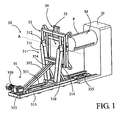
- the figures 1 and 2 illustrate a first embodiment of a handling device 30, according to the invention, arranged to switch a load C by a quarter of a turn and to perform in addition the loading and / or unloading of this load C on another machine, such as a reel D provided with a mandrel M adapted to receive the load C.
- This load C may be a sheet metal coil, as shown in the figures, deposited by a forklift truck or the like, and intended to feed a reel located at the head of a production line, or an unfinished sheet metal reel to take back from the reel.
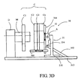
- This charge C may also consist of a stack of metal coils, as shown schematically in FIG. 3D figure , intended to feed a reel, the reels being deposited one after the other.
- the handling device 30 comprises a frame 31 movable in translation in guide rails 313 fixed to the ground in the axis of a reel D, this frame being coupled to drive means 35. It comprises a base 310 provided with rolling means housed in the guide rails 313, surmounted by a bracket 311 carrying at its free end a bearing 312 defining the axis of rotation A.
- the frame 31 carries a support 32 adapted to receive a load C such that a coil of sheet metal or the like.
- This support 32 comprises a frame or the like, rotatable about the axis of rotation A between at least one position with a vertical axis V and a position with a horizontal axis H, and vice versa.
- the axis of rotation A is in this example offset.
- the drive means 35 comprise an actuator 350 such as a geared motor or the like coupled to the frame 31 by a transmission such as a pinion and chain system 351, the chain circulating in a closed loop in the U-shaped guide rails 313. Any other known transmission may also be suitable. They also comprise a stand 352 which extends between a fixed abutment 353 integral with the guide rails 313 and a hinge 354 secured to the support 32 opposite the axis of rotation A. This stand 352 provides a locking function of the position of the support 32 and a rotational drive function of the support 32 in the counterclockwise direction R 'to move it from its horizontal axis position H to its vertical axis position V, as illustrated in FIGS. FIGS. 2A to 2C .
- an actuator 350 such as a geared motor or the like coupled to the frame 31 by a transmission such as a pinion and chain system 351, the chain circulating in a closed loop in the U-shaped guide rails 313. Any other known transmission may also be suitable.
- They also
- FIGS. 2A to 2C The operation of the handling device 30 is explained with reference to FIGS. 2A to 2C in which the device is shown empty.
- the handling device 30 In the position illustrated in Figure 2C the handling device 30 is waiting to receive a load C, is remote from the reel D and the support 32 is in its position with a vertical axis V.
- the support 32 When a load C is deposited on the support 32, the latter remains locked in its position with vertical axis V thanks to the stand 352 bearing against the fixed stop 353.
- the startup of the actuator 350 generates the movement of the frame 31 to the reel D and allows the rotation of the support 32 under the effect of gravity G.
- the articulation 354 of the stand 352 travels in a clockwise circle R centered on the fixed stop 353, until the support 32 reaches its position with a horizontal axis H illustrated in FIG.
- FIG 7A delimited by a stop 314 provided on the frame 31, wherein the load C is facing the reel D.
- This first part of the race of the frame 31 is called L1 approach stroke. From this position, the frame 31 continues to move towards the reel D, driving with him the stand 352 whose foot runs in the guide rails 313, to an end stop 355 which stops the actuator 350 and defines the position of loading and / or unloading of the reel D.
- This second part of the Chassis race 31 is called L2 load race.
- the load C can be transferred from the support 32 to the mandrel M as explained below.
- the return of the handling device 30 to its initial position illustrated in FIG. Figure 2C is performed by reversing the direction of rotation of the actuator 350 to drive the frame 31 in the opposite direction to the reel D.
- the frame 31 retreats a stroke L2 causing the stand 352 to its fixed stop 353 (cf. Fig. 2A ).
- the frame 31 continues its displacement opposite the reel D and the stand 352 generates the rotation of the support 32 about its axis of rotation A in the anticlockwise direction R '(cf. Fig. 2B ) to move from its position with horizontal axis H to its position with vertical axis V (cf. Fig. 2C ).
- the handling device 30 comprises means for holding and positioning 36 of the load C on the support 32 to prevent any risk of the load C falling and to ensure alignment with the mandrel M of the reel D to be loaded.
- the support 32 is preferably perforated to allow the passage of the mandrel M through said support 32.
- the support 32 consists of a frame defining a central opening 33 sufficient to receive the mandrel M in the example of the figure 3A
- the holding and positioning means 36 are in the form of a hook 360 adapted to bear on the internal bore of the load C.
- This hook 360 is slidably mounted on the support 32 and its radial position is adjustable to the means of threaded rods 361 for aligning the axis of the load C with the axis of the mandrel M of the reel D. This adjustment is therefore made at the time of putting into operation of the handling device 30.
- the reel D is equipped with an automatic expansion mandrel M and the jaws of the mandrel M are arranged so as to provide a passage P (cf. Fig. 1 ) for the hook 360 when loading and unloading the reel D.
- the hook 360 must be movable in radial translation on the support 32 by means for example of the cylinders 362, as shown in FIG. figure 3B . This radial translation makes it possible to vertically deposit the load C on the jaws of the mandrel M.
- the positioning means 36 are designed to bear on the outside of the load C by means for example of a cradle formed by support bars 363, a support V, or the like. In this case, these positioning means 36 are also movable in radial translation on the support 32 by means for example of cylinders 364 to adapt to the outer diameter of the load C.
- the handling device 30, can also be arranged to switch a load C consisting of a stack of several coils of sheets C1, C2, C3, Cn, as packaged, as shown in FIG. 3D figure .
- the positioning means 36 are radially movable on the support 32 by cylinders 364 and carry the load C by its outer diameter by means of axially movable support arms 365.
- the support arms 365 are axially movable to allow the removal of a single coil C1 at a time on the mandrel M of the reel D.
- the positioning means 36 can also carry the load C by its internal bore as in examples of Figures 3A and 3B , and in this case, the hook 360 is also axially movable.
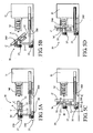
- the cam ramp 356 comprises a first inclined section corresponding to the stroke L1 at during which the frame 31 moves in translation towards the reel D and the support 32 switches from its vertical axis position V to its position with a horizontal axis H (cf. Fig. 4A and 4B ), followed by a second horizontal section corresponding to the stroke L2 during which the frame 32 continues to move in translation to bring the load C to the mandrel M of the reel D (cf. Fig. 4C and 4D ).
- the figure 4D illustrates the manner in which the handling device 30 of the invention makes it possible to load the reel D without the use of other handling equipment thanks to the support 32 which allows the mandrel M to pass through its central opening 33 in order to be able to deposit the load therein. C when the mandrel M extends.
- FIGS. 5A to 5D illustrate another alternative embodiment of the handling device 30 of the invention wherein the axis of rotation A of the support 32 is substantially coincidental with the center of gravity G of said support 32 plus the load C and in which the tilting of the support 32 between its positions with vertical axis V and horizontal axis H and vice versa is effected by additional drive means 37.
- They comprise an actuator 370 such as a motor, a geared motor, a jack, coupled in direct drive or by via a pinion / rack mechanical transmission or the like, to a drive shaft coincident with the axis of rotation A.
- the vertical axis V and horizontal axis positions H are delimited either by programming the control the actuator 370, or by limit switches provided on the frame 31 and not shown.
- the chassis 31 is mounted on rolling means 38 and coupled to the reel D by rails or telescopic guides 380 arranged to delimit the races L1 and L2 of the handling device 30 necessary for the loading and unloading of the reel. D.
- the displacement of the frame 31 is controlled by the actuator 350 and any type of mechanical transmission coupled to the rails or telescopic guides 380.
- the support 32 has a central opening 33 for the passage of the mandrel M during loading of the reel D and the holding and positioning means 36 of the load C for example in the form of a hook 360 adjustable in radial position.
- FIGS. 6A to 6D illustrate a second embodiment of a handling device 40 according to the invention in which the frame 31 is mounted on a wheeled vehicle 41 operated by an operator, this rolling machine 41 constituting drive means of said frame 31 and having advantage of not being dedicated to a reel D in particular, but can feed different reels D with the same device.
- the frame 31 is similar to that of the previous example and also comprises additional drive means 37 for tilting the support 32 from a vertical axis position V to a horizontal axis position H and vice versa.
- the support 32 is also in accordance with the preceding examples in that it comprises a central opening 33 for the passage of the mandrel M and means for holding and positioning 36 of the load C.
- the rolling machine 41 comprises vertical guide columns 410 or similar, in or on which slides the frame 31 and lifting means 411, for example in the form of jacks, to move the frame 31 vertically and position the support 32 relative to the axis of the mandrel M of a given reel D.
- This construction makes it possible to have a handling device 40 that is versatile and adaptable to different types of reels D.
- indexing stations 50 near the reels D (cf. Fig. 7A and 7B ) arranged to receive at least two coils C waiting, arranged side by side in a vertical axis position, and intended to be taken by the handling device 40: for example a full reel waiting to load on the reel D and a reel unfinished from the reel D.
- This indexing station 50 comprises a receiving plate 51 worn by feet 52.
- the receiving plate 51 has at the right of each coil C a central opening 53 allowing the passage of the support 32 of the handling device 40 under the coil C.
- the feet 52 delimit to the right of each coil C an indexing housing 54 adapted to receive the feet of the rolling machine 41 to be able to load a reel pending.
- the lifting means 411 of the handling device 40 can lower the support 32 under the coil C to be taken.
- the exemplary embodiments of figures 5 and 6 may comprise a support 32 similar to that of the exemplary embodiments of Figures 1 to 4 whose center of gravity G is offset relative to the axis of rotation A to overcome the additional drive means 37.
Landscapes
- Engineering & Computer Science (AREA)
- Mechanical Engineering (AREA)
- Replacement Of Web Rolls (AREA)
- Load-Engaging Elements For Cranes (AREA)
Claims (14)
- Vorrichtung (30, 40) zur Handhabung einer Last (C), z.B. einer Blechspule, mit einem Träger (32), der besagte Last (C) tragen kann, wobei dieser Träger (32) auf einem Gestell (31) zwischen zumindest einer ersten sogenannten Vertikal-Achsenstellung (V), in der die Achse der Last (C) vertikal ist, und einer zweiten sogenannten Horizontal-Achsenstellung (H), in der die Achse der Last (C) horizontal ist, und umgekehrt, drehend gelagert ist, wobei besagtes Gestell (31) an Antriebsmittel (35, 41) gekoppelt ist, um beweglich zu sein, um besagte Last (C) auf eine andere Maschine wie ein Abwickler (D) laden oder von dieser Maschine entladen zu können, und wobei besagter Träger (32) Mittel zum Festhalten und Positionieren (36) von besagter Last (C) beträgt, die ausgelegt sind, um besagte Last (C) während ihres Stellungswechsels festzuhalten und besagte Last (C) auf besagte Maschine abzulegen oder von dieser wieder aufzunehmen, dadurch gekennzeichnet, dass besagter Träger (32) eine zentrale Öffnung (33) aufweist, die dazu bestimmt ist, während der Be- und Entladevorgänge von besagter Last (C) den Durchgang eines Doms (M) eines Abwickers (D) zu erlauben, und dadurch, dass besagte Mittel zum Festhalten und Positionieren (36) radial und/oder axial auf besagtem Träger (32) translationsbeweglich sind, um die Achse der Last (C) und die Achse des Dorns (M) eines Abwicklers (D) während der besagten Vorgänge aufeinander auszurichten.
- Vorrichtung zur Handhabung nach Anspruch 1, dadurch gekennzeichnet, dass die Drehachse (A) des Trägers (32) auf dem Gestell (31) in Bezug auf den Schwerpunkt (G) der Gruppe bestehend aus besagtem Träger (32) zusammen mit besagter Last (C) versetzt ist, wobei dieser Träger ausgelegt ist, um unter dem Einfluss der Schwerkraft in eine Drehrichtung (R) zu kippen, um von der Vertikal-Achsenstellung (V) in die Horizontal-Achsenstellung (H) zu übergehen.
- Vorrichtung zur Handhabung nach Anspruch 1, dadurch gekennzeichnet, dass die Drehachse (A) des Trägers (32) auf dem Gestell (31) im Wesentlichen mit dem Schwerpunkt (G) der Gruppe bestehend aus besagtem Träger (32) zusammen mit besagter Last (C) zusammenfällt, und dadurch, dass er zusätzliche an besagten Träger (32) gekoppelte Antriebsmittel (37) beträgt, um ihn von der Vertikal-Achsenstellung (V) in die Horizontal-Achsenstellung (H) und umgekehrt zu kippen.
- Vorrichtung nach Anspruch 1, dadurch gekennzeichnet, dass besagtes Gestell (31) in Führungsschienen (313, 380) translationsbeweglich ist, und dadurch, dass besagte Antriebsmittel (35) zumindest einen über eine Kraftübertragung (351) an besagtes Gestell (31) gekoppelten Antrieb (350) betragen.
- Vorrichtung nach Ansprüche 2 und 4, dadurch gekennzeichnet, dass besagte Antriebsmittel (35) an besagten Träger (32) gekoppelt sind, um ihn in die entgegengesetzte Drehrichtung (R') zu kippen, um ihn von seiner Horizontal-Achsenstellung (H) in seine Vertikal-Achsenstellung (V) zu bringen.
- Vorrichtung nach Anspruch 5, dadurch gekennzeichnet, dass besagte Antriebsmittel (35) eine Stütze (352) betragen, die sich zwischen einem an den Führungsschienen (313) befestigten Festanschlag (353) und ein an besagtem Träger (32) gegenüber der besagten Drehachse (A) befestigtes Gelenk (354) erstreckt, wobei besagte Stütze (352) ausgelegt ist, um besagten Träger (32) in seiner Vertikal-Achsenstellung (V) zu blockieren.
- Vorrichtung nach Anspruch 5, dadurch gekennzeichnet, dass besagte Antriebsmittel (35) eine feste Nockenrampe (356) betragen, auf der eine an besagtem Träger (32), gegenüber der besagte Drehachse (A) befestigte Rolle (357) verfährt.
- Vorrichtung nach einem der Ansprüche 6 und 7, dadurch gekennzeichnet, dass besagte Führungsschienen (313) in der Verlängerung eines Abwicklers (D) angeordnet sind, und dadurch, dass besagte Antriebsmittel (35) ausgelegt sind, um besagtes Gestell (31) um einen zusätzlichen Weg (L2) zu verfahren, um besagten Abwickler (D) zu be- und/oder entladen wenn besagter Träger (32) in der Horizontal-Achsenstellung (H) ist.
- Vorrichtung nach Anspruch 8, dadurch gekennzeichnet, dass besagtes Gestell (31) zumindest einen Anschlag (314) beträgt, der besagte Horizontal-Achsenstellung (H) von besagtem Träger (32) bestimmt.
- Vorrichtung nach Anspruch 8, dadurch gekennzeichnet, dass besagte Nockenrampe (356) einen ersten Abschnitt beträgt, der dem Weg (L1) des besagten Gestells (31) während der Drehung des besagten Trägers (32) entspricht, und einen zweiten Abschnitt, der dem zusätzlichen Weg (L2) zum Be- und/oder Entladen des Abwicklers (D) entspricht.
- Vorrichtung nach Anspruch 1, dadurch gekennzeichnet, dass besagtes Gestell (31) auf ein Fahrzeug (41) montiert ist, das die besagten Antriebsmittel bildet.
- Vorrichtung nach Anspruch 11, dadurch gekennzeichnet, dass besagtes Fahrzeug (41) Hebemittel (411) beträgt, die ausgelegt sind, um besagtes Gestell (31) in der Höhe zu verstellen.
- Vorrichtung nach Anspruch 1, dadurch gekennzeichnet, dass besagte Mittel zum Festhalten und Positionieren (36) der Last (C) einen Haken (360) betragen, der auf der Innenbohrung von Last (C) zur Auflage kommen kann.
- Vorrichtung nach Anspruch 1, dadurch gekennzeichnet, dass besagte Mittel zum Festhalten und Positionieren (36) der Last (C) eine Wiege (363) betragen, die auf der Außenfläche von Last (C) zur Auflage kommen kann.
Applications Claiming Priority (2)
| Application Number | Priority Date | Filing Date | Title |
|---|---|---|---|
| FR0703779A FR2916750B1 (fr) | 2007-05-29 | 2007-05-29 | Dispositif de manutention d'une charge telle qu'une bobine de toile. |
| PCT/FR2008/000724 WO2009004160A2 (fr) | 2007-05-29 | 2008-05-28 | Dispositif de manutention d'une charge telle qu'une bobine de tole |
Publications (2)
| Publication Number | Publication Date |
|---|---|
| EP2167251A2 EP2167251A2 (de) | 2010-03-31 |
| EP2167251B1 true EP2167251B1 (de) | 2015-03-04 |
Family
ID=38826557
Family Applications (1)
| Application Number | Title | Priority Date | Filing Date |
|---|---|---|---|
| EP08805615.5A Not-in-force EP2167251B1 (de) | 2007-05-29 | 2008-05-28 | Vorrichtung zur handhabung einer last, z. b. einer blechspule |
Country Status (4)
| Country | Link |
|---|---|
| US (1) | US20100172729A1 (de) |
| EP (1) | EP2167251B1 (de) |
| FR (1) | FR2916750B1 (de) |
| WO (1) | WO2009004160A2 (de) |
Cited By (1)
| Publication number | Priority date | Publication date | Assignee | Title |
|---|---|---|---|---|
| EP3473581A1 (de) | 2017-10-19 | 2019-04-24 | Dimeco S.A.S. | Förderverfahren einer last, insbesondere einer blechrolle, fördervorrichtung, die die umsetzung dieses verfahrens ermöglicht, und hubgerät, das mit einer solchen vorrichtung ausgestattet ist |
Families Citing this family (10)
| Publication number | Priority date | Publication date | Assignee | Title |
|---|---|---|---|---|
| CN103962499B (zh) * | 2014-05-29 | 2017-05-10 | 德清华腾金属材料有限公司 | 链条扁丝料松圈设备的放料装置 |
| CN103978067B (zh) * | 2014-05-29 | 2016-04-06 | 德清华腾金属材料有限公司 | 一种链条扁丝料松圈设备的夹紧装置 |
| CN103962498B (zh) * | 2014-05-29 | 2016-04-06 | 德清华腾金属材料有限公司 | 一种链条扁丝料松圈设备 |
| FR3022521B1 (fr) * | 2014-06-20 | 2017-10-13 | Nexter Systems | Dispositif de manutention pour une chenille de vehicule, dispositif et procede de changement de semelles de chenille mettant en oeuvre un tel dispositif de manutention. |
| US9132696B2 (en) * | 2015-02-11 | 2015-09-15 | Glg Farms Llc | Tire manipulation system |
| CN107953914A (zh) * | 2017-11-27 | 2018-04-24 | 上海市质量监督检验技术研究院 | 一种搬运装置 |
| CN108995881A (zh) * | 2018-07-19 | 2018-12-14 | 唐山新宝泰钢铁有限公司 | 带钢推卷装置及其操作方法 |
| WO2020247767A1 (en) * | 2019-06-07 | 2020-12-10 | Victor Manuel Quinones | Device and system for separating and packaging steel slit coils |
| SE2350542A1 (en) * | 2023-05-04 | 2024-04-02 | Spiro Sweden AB | Sheet metal decoiler |
| CN117465969B (zh) * | 2023-11-10 | 2025-11-28 | 深圳市高捷力科技有限公司 | 一种用于装卸卷材的装载装置 |
Family Cites Families (11)
| Publication number | Priority date | Publication date | Assignee | Title |
|---|---|---|---|---|
| US3395813A (en) * | 1966-09-09 | 1968-08-06 | United States Steel Corp | Apparatus for turning products |
| GB1212521A (en) * | 1967-02-28 | 1970-11-18 | Davy & United Eng Co Ltd | Apparatus for transferring elongate metal sections |
| US3476267A (en) * | 1968-07-17 | 1969-11-04 | Autoquip Corp | Turning table for metal coils and the like |
| US3753505A (en) * | 1971-03-10 | 1973-08-21 | Fmc Corp | Article roll-over device |
| DD96919A1 (de) * | 1972-05-24 | 1973-04-12 | ||
| US4322198A (en) * | 1980-04-16 | 1982-03-30 | Northern Telecom Limited | Coil handling device |
| US4941798A (en) * | 1987-10-13 | 1990-07-17 | Sft Ag Spontanfordertechnik | Means for manipulating and transporting loads |
| US5332351A (en) * | 1991-06-25 | 1994-07-26 | Nelson Jacqueline S | Coil unloading and transportation apparatus and method |
| JP3523916B2 (ja) * | 1994-09-02 | 2004-04-26 | 新谷製鎖有限会社 | コイル状圧延重量物の起伏装置 |
| JPH10120132A (ja) * | 1996-10-21 | 1998-05-12 | Mitsubishi Heavy Ind Ltd | コイル反転装置 |
| JP4642393B2 (ja) * | 2004-07-02 | 2011-03-02 | イーグルクランプ株式会社 | 起伏クランプ |
-
2007
- 2007-05-29 FR FR0703779A patent/FR2916750B1/fr not_active Expired - Fee Related
-
2008
- 2008-05-28 EP EP08805615.5A patent/EP2167251B1/de not_active Not-in-force
- 2008-05-28 US US12/602,027 patent/US20100172729A1/en not_active Abandoned
- 2008-05-28 WO PCT/FR2008/000724 patent/WO2009004160A2/fr not_active Ceased
Cited By (1)
| Publication number | Priority date | Publication date | Assignee | Title |
|---|---|---|---|---|
| EP3473581A1 (de) | 2017-10-19 | 2019-04-24 | Dimeco S.A.S. | Förderverfahren einer last, insbesondere einer blechrolle, fördervorrichtung, die die umsetzung dieses verfahrens ermöglicht, und hubgerät, das mit einer solchen vorrichtung ausgestattet ist |
Also Published As
| Publication number | Publication date |
|---|---|
| WO2009004160A3 (fr) | 2009-02-19 |
| EP2167251A2 (de) | 2010-03-31 |
| FR2916750A1 (fr) | 2008-12-05 |
| WO2009004160A2 (fr) | 2009-01-08 |
| US20100172729A1 (en) | 2010-07-08 |
| FR2916750B1 (fr) | 2010-04-02 |
Similar Documents
| Publication | Publication Date | Title |
|---|---|---|
| WO2009004160A2 (fr) | Dispositif de manutention d'une charge telle qu'une bobine de tole | |
| EP3473581B1 (de) | Förderverfahren einer last, insbesondere einer blechrolle, fördervorrichtung, die die umsetzung dieses verfahrens ermöglicht, und hubgerät, das mit einer solchen vorrichtung ausgestattet ist | |
| BE1006857A3 (fr) | Installation pour garnir d'une maconnerie de briques une paroi interieure d'une enceinte. | |
| BE1005112A5 (fr) | Installation de parking. | |
| EP1029619A2 (de) | Stangenzufuhr zum kürzen von Stangen an Werkzeugmaschinen | |
| EP2957487B1 (de) | Instandsetzungsvorrichtung für eine fahrzeug-laufkette, vorrichtung und verfahren zum wechseln der ketten-laufflächen mithilfe dieser instandsetzungsvorrichtung | |
| FR2687654A1 (fr) | Structure pour permettre de charger ou decharger des marchandises a transporter avec un dispositif de manutention a bras de levage hydraulique. | |
| FR2623891A1 (fr) | Installation pour briqueter la paroi interieure d'une enceinte | |
| FR3143578A3 (fr) | Système empileur adapté pour une structure, rack pour palettes et conteneur individuel | |
| FR2598142A1 (fr) | Chariot elevateur a fourche avec un bloc de commande orientable et un ensemble porte-charge mobile en hauteur. | |
| EP2035310B1 (de) | Spuler mit expandierbarem dorn für eine rolle | |
| EP0252936B1 (de) | Vorrichtung zum abheben von bogenpaketen, insbesondere von papier, von stapeln | |
| EP0226075A1 (de) | Automatisierte Anlage zum Ausmauern der Innenwand eines Gefässes | |
| FR2812281A1 (fr) | Dispositif de chargement et/ou de dechargement de support de pile et poste de chargement et/ou dechargement correspondant | |
| EP1165425B1 (de) | Vorrichtung zum handhaben von teilen, insbesondere bandmetallrollen und apparat ausgestattet mit einer solchen vorrichtung | |
| FR2543528A1 (fr) | Dispositif de retenue pour element de prehension de chariot elevateur | |
| FR2482570A1 (fr) | Dispositif pour l'enroulement automatique de produits filiformes, notamment de fil metallique | |
| EP0042463A1 (de) | Selbsttätige Förderanlage | |
| FR2930536A1 (fr) | Potence mobile de chantier | |
| FR2491445A1 (fr) | Dispositif et procede de manutention et d'empilage d'objets parallelepipediques | |
| EP2666605B1 (de) | Anlage zur Herstellung von Bauelementen | |
| FR2795012A1 (fr) | Dispositif de transfert de pieces a usiner | |
| FR2514735A1 (fr) | Procede et installation pour le chargement de palettes avec des charges isolees differentes d'une palette a une autre | |
| FR2609428A1 (fr) | Dispositif d'alimentation d'une presse a partir de deux piles de flans de tole | |
| FR2813596A1 (fr) | Installation et procede de conditionnement d'une feuille de materiau de moulage |
Legal Events
| Date | Code | Title | Description |
|---|---|---|---|
| PUAI | Public reference made under article 153(3) epc to a published international application that has entered the european phase |
Free format text: ORIGINAL CODE: 0009012 |
|
| 17P | Request for examination filed |
Effective date: 20091123 |
|
| AK | Designated contracting states |
Kind code of ref document: A2 Designated state(s): AT BE BG CH CY CZ DE DK EE ES FI FR GB GR HR HU IE IS IT LI LT LU LV MC MT NL NO PL PT RO SE SI SK TR |
|
| AX | Request for extension of the european patent |
Extension state: AL BA MK RS |
|
| DAX | Request for extension of the european patent (deleted) | ||
| GRAP | Despatch of communication of intention to grant a patent |
Free format text: ORIGINAL CODE: EPIDOSNIGR1 |
|
| INTG | Intention to grant announced |
Effective date: 20141003 |
|
| GRAS | Grant fee paid |
Free format text: ORIGINAL CODE: EPIDOSNIGR3 |
|
| GRAA | (expected) grant |
Free format text: ORIGINAL CODE: 0009210 |
|
| AK | Designated contracting states |
Kind code of ref document: B1 Designated state(s): AT BE BG CH CY CZ DE DK EE ES FI FR GB GR HR HU IE IS IT LI LT LU LV MC MT NL NO PL PT RO SE SI SK TR |
|
| REG | Reference to a national code |
Ref country code: GB Ref legal event code: FG4D Free format text: NOT ENGLISH |
|
| REG | Reference to a national code |
Ref country code: CH Ref legal event code: EP |
|
| REG | Reference to a national code |
Ref country code: IE Ref legal event code: FG4D Free format text: LANGUAGE OF EP DOCUMENT: FRENCH |
|
| REG | Reference to a national code |
Ref country code: AT Ref legal event code: REF Ref document number: 713387 Country of ref document: AT Kind code of ref document: T Effective date: 20150415 |
|
| REG | Reference to a national code |
Ref country code: DE Ref legal event code: R096 Ref document number: 602008036991 Country of ref document: DE Effective date: 20150416 |
|
| REG | Reference to a national code |
Ref country code: AT Ref legal event code: MK05 Ref document number: 713387 Country of ref document: AT Kind code of ref document: T Effective date: 20150304 Ref country code: NL Ref legal event code: VDEP Effective date: 20150304 |
|
| PG25 | Lapsed in a contracting state [announced via postgrant information from national office to epo] |
Ref country code: LT Free format text: LAPSE BECAUSE OF FAILURE TO SUBMIT A TRANSLATION OF THE DESCRIPTION OR TO PAY THE FEE WITHIN THE PRESCRIBED TIME-LIMIT Effective date: 20150304 Ref country code: FI Free format text: LAPSE BECAUSE OF FAILURE TO SUBMIT A TRANSLATION OF THE DESCRIPTION OR TO PAY THE FEE WITHIN THE PRESCRIBED TIME-LIMIT Effective date: 20150304 Ref country code: SE Free format text: LAPSE BECAUSE OF FAILURE TO SUBMIT A TRANSLATION OF THE DESCRIPTION OR TO PAY THE FEE WITHIN THE PRESCRIBED TIME-LIMIT Effective date: 20150304 Ref country code: ES Free format text: LAPSE BECAUSE OF FAILURE TO SUBMIT A TRANSLATION OF THE DESCRIPTION OR TO PAY THE FEE WITHIN THE PRESCRIBED TIME-LIMIT Effective date: 20150304 Ref country code: HR Free format text: LAPSE BECAUSE OF FAILURE TO SUBMIT A TRANSLATION OF THE DESCRIPTION OR TO PAY THE FEE WITHIN THE PRESCRIBED TIME-LIMIT Effective date: 20150304 Ref country code: NO Free format text: LAPSE BECAUSE OF FAILURE TO SUBMIT A TRANSLATION OF THE DESCRIPTION OR TO PAY THE FEE WITHIN THE PRESCRIBED TIME-LIMIT Effective date: 20150604 |
|
| REG | Reference to a national code |
Ref country code: LT Ref legal event code: MG4D |
|
| PG25 | Lapsed in a contracting state [announced via postgrant information from national office to epo] |
Ref country code: LV Free format text: LAPSE BECAUSE OF FAILURE TO SUBMIT A TRANSLATION OF THE DESCRIPTION OR TO PAY THE FEE WITHIN THE PRESCRIBED TIME-LIMIT Effective date: 20150304 Ref country code: AT Free format text: LAPSE BECAUSE OF FAILURE TO SUBMIT A TRANSLATION OF THE DESCRIPTION OR TO PAY THE FEE WITHIN THE PRESCRIBED TIME-LIMIT Effective date: 20150304 Ref country code: GR Free format text: LAPSE BECAUSE OF FAILURE TO SUBMIT A TRANSLATION OF THE DESCRIPTION OR TO PAY THE FEE WITHIN THE PRESCRIBED TIME-LIMIT Effective date: 20150605 |
|
| PG25 | Lapsed in a contracting state [announced via postgrant information from national office to epo] |
Ref country code: NL Free format text: LAPSE BECAUSE OF FAILURE TO SUBMIT A TRANSLATION OF THE DESCRIPTION OR TO PAY THE FEE WITHIN THE PRESCRIBED TIME-LIMIT Effective date: 20150304 |
|
| PG25 | Lapsed in a contracting state [announced via postgrant information from national office to epo] |
Ref country code: EE Free format text: LAPSE BECAUSE OF FAILURE TO SUBMIT A TRANSLATION OF THE DESCRIPTION OR TO PAY THE FEE WITHIN THE PRESCRIBED TIME-LIMIT Effective date: 20150304 Ref country code: PT Free format text: LAPSE BECAUSE OF FAILURE TO SUBMIT A TRANSLATION OF THE DESCRIPTION OR TO PAY THE FEE WITHIN THE PRESCRIBED TIME-LIMIT Effective date: 20150706 Ref country code: CZ Free format text: LAPSE BECAUSE OF FAILURE TO SUBMIT A TRANSLATION OF THE DESCRIPTION OR TO PAY THE FEE WITHIN THE PRESCRIBED TIME-LIMIT Effective date: 20150304 Ref country code: RO Free format text: LAPSE BECAUSE OF FAILURE TO SUBMIT A TRANSLATION OF THE DESCRIPTION OR TO PAY THE FEE WITHIN THE PRESCRIBED TIME-LIMIT Effective date: 20150304 Ref country code: SK Free format text: LAPSE BECAUSE OF FAILURE TO SUBMIT A TRANSLATION OF THE DESCRIPTION OR TO PAY THE FEE WITHIN THE PRESCRIBED TIME-LIMIT Effective date: 20150304 |
|
| PG25 | Lapsed in a contracting state [announced via postgrant information from national office to epo] |
Ref country code: PL Free format text: LAPSE BECAUSE OF FAILURE TO SUBMIT A TRANSLATION OF THE DESCRIPTION OR TO PAY THE FEE WITHIN THE PRESCRIBED TIME-LIMIT Effective date: 20150304 Ref country code: IS Free format text: LAPSE BECAUSE OF FAILURE TO SUBMIT A TRANSLATION OF THE DESCRIPTION OR TO PAY THE FEE WITHIN THE PRESCRIBED TIME-LIMIT Effective date: 20150704 |
|
| REG | Reference to a national code |
Ref country code: DE Ref legal event code: R097 Ref document number: 602008036991 Country of ref document: DE |
|
| REG | Reference to a national code |
Ref country code: CH Ref legal event code: PL |
|
| PLBE | No opposition filed within time limit |
Free format text: ORIGINAL CODE: 0009261 |
|
| STAA | Information on the status of an ep patent application or granted ep patent |
Free format text: STATUS: NO OPPOSITION FILED WITHIN TIME LIMIT |
|
| PG25 | Lapsed in a contracting state [announced via postgrant information from national office to epo] |
Ref country code: DK Free format text: LAPSE BECAUSE OF FAILURE TO SUBMIT A TRANSLATION OF THE DESCRIPTION OR TO PAY THE FEE WITHIN THE PRESCRIBED TIME-LIMIT Effective date: 20150304 Ref country code: LI Free format text: LAPSE BECAUSE OF NON-PAYMENT OF DUE FEES Effective date: 20150531 Ref country code: MC Free format text: LAPSE BECAUSE OF FAILURE TO SUBMIT A TRANSLATION OF THE DESCRIPTION OR TO PAY THE FEE WITHIN THE PRESCRIBED TIME-LIMIT Effective date: 20150304 Ref country code: LU Free format text: LAPSE BECAUSE OF FAILURE TO SUBMIT A TRANSLATION OF THE DESCRIPTION OR TO PAY THE FEE WITHIN THE PRESCRIBED TIME-LIMIT Effective date: 20150528 Ref country code: CH Free format text: LAPSE BECAUSE OF NON-PAYMENT OF DUE FEES Effective date: 20150531 |
|
| 26N | No opposition filed |
Effective date: 20151207 |
|
| GBPC | Gb: european patent ceased through non-payment of renewal fee |
Effective date: 20150604 |
|
| REG | Reference to a national code |
Ref country code: IE Ref legal event code: MM4A |
|
| PG25 | Lapsed in a contracting state [announced via postgrant information from national office to epo] |
Ref country code: SI Free format text: LAPSE BECAUSE OF FAILURE TO SUBMIT A TRANSLATION OF THE DESCRIPTION OR TO PAY THE FEE WITHIN THE PRESCRIBED TIME-LIMIT Effective date: 20150304 |
|
| PG25 | Lapsed in a contracting state [announced via postgrant information from national office to epo] |
Ref country code: IE Free format text: LAPSE BECAUSE OF NON-PAYMENT OF DUE FEES Effective date: 20150528 Ref country code: GB Free format text: LAPSE BECAUSE OF NON-PAYMENT OF DUE FEES Effective date: 20150604 |
|
| REG | Reference to a national code |
Ref country code: FR Ref legal event code: PLFP Year of fee payment: 9 |
|
| PG25 | Lapsed in a contracting state [announced via postgrant information from national office to epo] |
Ref country code: MT Free format text: LAPSE BECAUSE OF FAILURE TO SUBMIT A TRANSLATION OF THE DESCRIPTION OR TO PAY THE FEE WITHIN THE PRESCRIBED TIME-LIMIT Effective date: 20150304 |
|
| REG | Reference to a national code |
Ref country code: FR Ref legal event code: PLFP Year of fee payment: 10 |
|
| PG25 | Lapsed in a contracting state [announced via postgrant information from national office to epo] |
Ref country code: BG Free format text: LAPSE BECAUSE OF FAILURE TO SUBMIT A TRANSLATION OF THE DESCRIPTION OR TO PAY THE FEE WITHIN THE PRESCRIBED TIME-LIMIT Effective date: 20150304 Ref country code: HU Free format text: LAPSE BECAUSE OF FAILURE TO SUBMIT A TRANSLATION OF THE DESCRIPTION OR TO PAY THE FEE WITHIN THE PRESCRIBED TIME-LIMIT; INVALID AB INITIO Effective date: 20080528 |
|
| PG25 | Lapsed in a contracting state [announced via postgrant information from national office to epo] |
Ref country code: CY Free format text: LAPSE BECAUSE OF FAILURE TO SUBMIT A TRANSLATION OF THE DESCRIPTION OR TO PAY THE FEE WITHIN THE PRESCRIBED TIME-LIMIT Effective date: 20150304 |
|
| PG25 | Lapsed in a contracting state [announced via postgrant information from national office to epo] |
Ref country code: BE Free format text: LAPSE BECAUSE OF NON-PAYMENT OF DUE FEES Effective date: 20150531 |
|
| PG25 | Lapsed in a contracting state [announced via postgrant information from national office to epo] |
Ref country code: TR Free format text: LAPSE BECAUSE OF FAILURE TO SUBMIT A TRANSLATION OF THE DESCRIPTION OR TO PAY THE FEE WITHIN THE PRESCRIBED TIME-LIMIT Effective date: 20150304 |
|
| REG | Reference to a national code |
Ref country code: FR Ref legal event code: PLFP Year of fee payment: 11 |
|
| REG | Reference to a national code |
Ref country code: DE Ref legal event code: R082 Ref document number: 602008036991 Country of ref document: DE Representative=s name: LAURENT CHARRAS, FR Ref country code: DE Ref legal event code: R081 Ref document number: 602008036991 Country of ref document: DE Owner name: DIMECO, FR Free format text: FORMER OWNER: ROTOBLOC-PSP SARL, PIREY, FR |
|
| PGFP | Annual fee paid to national office [announced via postgrant information from national office to epo] |
Ref country code: DE Payment date: 20240613 Year of fee payment: 17 |
|
| PGFP | Annual fee paid to national office [announced via postgrant information from national office to epo] |
Ref country code: IT Payment date: 20240517 Year of fee payment: 17 Ref country code: FR Payment date: 20240521 Year of fee payment: 17 |
|
| REG | Reference to a national code |
Ref country code: DE Ref legal event code: R119 Ref document number: 602008036991 Country of ref document: DE |
|
| PG25 | Lapsed in a contracting state [announced via postgrant information from national office to epo] |
Ref country code: DE Free format text: LAPSE BECAUSE OF NON-PAYMENT OF DUE FEES Effective date: 20251202 |
|
| PG25 | Lapsed in a contracting state [announced via postgrant information from national office to epo] |
Ref country code: IT Free format text: LAPSE BECAUSE OF NON-PAYMENT OF DUE FEES Effective date: 20250528 |
|
| PG25 | Lapsed in a contracting state [announced via postgrant information from national office to epo] |
Ref country code: FR Free format text: LAPSE BECAUSE OF NON-PAYMENT OF DUE FEES Effective date: 20250531 |