EP2174236B1 - Procédé et système pour une suppression dynamique de la distorsion de repliement - Google Patents
Procédé et système pour une suppression dynamique de la distorsion de repliement Download PDFInfo
- Publication number
- EP2174236B1 EP2174236B1 EP08789700.5A EP08789700A EP2174236B1 EP 2174236 B1 EP2174236 B1 EP 2174236B1 EP 08789700 A EP08789700 A EP 08789700A EP 2174236 B1 EP2174236 B1 EP 2174236B1
- Authority
- EP
- European Patent Office
- Prior art keywords
- sub
- digital audio
- signal
- far
- band
- Prior art date
- Legal status (The legal status is an assumption and is not a legal conclusion. Google has not performed a legal analysis and makes no representation as to the accuracy of the status listed.)
- Not-in-force
Links
Images


Classifications
-
- H—ELECTRICITY
- H04—ELECTRIC COMMUNICATION TECHNIQUE
- H04M—TELEPHONIC COMMUNICATION
- H04M9/00—Arrangements for interconnection not involving centralised switching
- H04M9/08—Two-way loud-speaking telephone systems with means for conditioning the signal, e.g. for suppressing echoes for one or both directions of traffic
- H04M9/082—Two-way loud-speaking telephone systems with means for conditioning the signal, e.g. for suppressing echoes for one or both directions of traffic using echo cancellers
Definitions
- the present invention relates generally to the field of aliasing suppression and more particularly to a method and system for aliasing suppression in wide band telephony echo canceller systems.
- WB wideband
- G722 16 KHz sampling rate (8KHz spectrum bandwidth) with division to two sub bands (SB) of 4 KHz each.
- the communication according to the standards, such as G722 includes transformation of the analog signal from the speakers end into digital signal, splitting the WB into two SB, encoding each of the two SB and transmission of the encoded sub bands over the network.
- the traditional approach at the receiving end suggests decoding both encoded sub bands and merging the two sub bands.
- this approach further requires processing a signal that is sampled at a relatively high sampling frequency. For example if this approach is applied on a G722 system, then the merged signal should be sampled at the rate of 16 KHz.
- the signal may be decoded on each of the two sub bands, but not merged immediately thereafter and by that enabling to perform echo cancelling and various DSP on low frequency sub-bands.
- each of the sub-band signals is carrying a significant non linear aliasing component.
- the advantage of low sampling frequency causes a non linear aliasing problem.
- the processing of two sub bands in half sampling rate provides a benefit only if there is an efficient and low cost method to suppress the non linear aliasing component that is contained in each of the two sub bands.
- US Patent No. 6 522 747 discloses single-sided subband filters.
- An aspect of an embodiment of the invention relates to a method and a system for suppressing a non linear aliasing component from an audio sub band channel.
- sub-bands near-end digital signal is passing through a dynamic anti aliasing suppressor (DAAS) wherein the level of aggressiveness applied by the DAAS is changing dynamically according to the activity of both near and far ends and also according to the relation between their activities, i.e. whose end is increasing/decreasing.
- DAAS dynamic anti aliasing suppressor
- alias suppression is performed on the sub-band near end digital signal by subtracting a simulated digital signal from the near-end sub-band digital signal, wherein the simulated digital signal is calculated after applying an anti aliasing suppression (AAS) on a sampled far-end sub-band digital signal wherein the level of the aliasing suppression is kept continuously at a predefined level.
- AAS anti aliasing suppression
- an efficient method and system for non linear aliasing cancellation enabling to perform echo cancelling and other DSP on a relatively low frequency sub bands, while performing these tasks with relatively reduced resources.
- a method for aliasing suppression in a sub-band speaker-phone system comprising receiving an analog audio signal from a near end analog audio input interface converting said analog audio signal into a near end digital audio signal using an A2D; receiving N ⁇ 2 sub-bands decoded digital audio data from a far-end, merging said N ⁇ 2 sub-bands decoded digital audio data into a wideband (WB) decoded digital audio data to be converted by D2A unit and provided to analog audio output interface; splitting said near-end digital audio signal into N ⁇ 2 near-end sub-bands digital audio signals; subtracting a simulated digital signal from said sub-band digital audio signal, wherein said simulated digital signal is created by an echo cancelling unit; and applying dynamic anti aliasing suppression (DAAS) with varying aggressiveness on each of said N ⁇ 2 near-end sub-band digital audio signals ;
- DAS dynamic anti aliasing suppression
- the varying aggressiveness is responsive to the activity of said far-end and the activity of said near-end analog audio input interfaceIn an exemplary embodiments of the invention the varying aggressiveness is defined at a predefined maximal level when only far-end is active, approximately zero when far-end is inactive and at predefined intermediate levels of aggressiveness when both far-end and near-end are simultaneously active.
- the DAAS is performed on the N ⁇ 2 near-end sub-bands signals before subtracting a simulated digital signal from said digital audio signal.
- the DASS is performed on the N ⁇ 2 near-end sub-bands signals after subtracting a simulated digital signal from said digital audio signal.
- the echo cancelling unit receives a signal that is sampled from said sub-bands decoded digital audio data from a far-end and suppressed by an anti aliasing suppressor (AAS) that is continuously active.
- AAS anti aliasing suppressor
- the AAS suppression level is approximately equal to said maximal level of said DAAS.
- the number N of sub-bans equals to two.
- the splitting the near-end digital audio is performed by a G722 QMF.
- the near end analog audio input interface is a microphone.
- the near end analog audio output interface is speaker.
- a method for aliasing suppression in a sub-bands audio system comprising providing near-end analog audio input interface; providing a far-end; transmitting near-end audio signal from said near-end to said far-end and receiving far-end audio from said far-end by said near-end; applying a dynamic anti aliasing suppression (DAAS) with varying aggressiveness on the near-end audio signal.
- DAAS dynamic anti aliasing suppression
- the varying aggressiveness is responsive to the activity of said far-end and the activity of said near-end.
- a speaker phone system that performs dynamic anti aliasing suppression on sub-bands digital audio signals, comprising: N ⁇ 2 sub-bands decoders that decode encoded digital audio data that is transmitted by a far-end audio source; a combining device for receiving and merging decoded audio data that is transmitted by said N ⁇ 2 sub-band decoders; a digital to analog converter that transforms the output from said combining device into an analog audio signal and provides the analog audio signal to an analog audio output interface; a near-end analog audio input interface that provides analog audio signal that is converted into digital audio signal by A2D unit and split into N ⁇ 2 sub-bands of digital audio signal; N dynamic anti aliasing suppressors (DAAS) where each of said N ⁇ 2 DAAS suppresses one of said N sub-bands of digital audio signal applying a varying level of aggressiveness; N subtraction units, each subtraction unit receives a suppressed sub-bands of digital audio data after being suppress
- DAAS dynamic anti alias
- Fig 1 shows a block diagram of a G722 compliant speaker-phone system 100 according to prior art design.
- the purpose of the system is to transmit audio from a near-end source to a far-end receiving member and vice versa, i.e. receiving audio from a far-end source by a near-end member.
- the main problem is to cancel the near side echo 183 which causes severe deterioration of the signal quality perceived on the far end.
- the system includes a microphone 186 and a speaker 180 located at the near-end.
- the analog audio signal that is created by the microphone 186 is converted to a digital audio signal that is sampled at 16 KHz by an analog to digital converter A2D 173 and proceeds to a quadrature mirror filter (QMF) splitter 133 after subtraction of a calculated echo 165 that is provided by an echo cancelling unit 162.
- the echo canceling unit functions in two modes: in the first mode when a control unit 153 provides an indication that only the far side is talking and the signal received by microphone 186 is only provided by a far-end 104, the echo canceling unit 162 attempts to reduce the signal at the residual point (res) 156 to zero usually by adapting its coefficients.
- the echo canceller function in this mode is to simulates and track the echo path 183.
- it does not adapt the echo cancelling unit 162 coefficients and just subtracts the estimated echo by the subtraction unit 165.
- subtraction unit 165 is typically implemented by an adder that adds the signal to be subtracted with a negative sign (this technique depends on a specific method of the signal presentation such as 1's complement or 2's complement), therefore the subtraction unit 165 appears with a plus sign and the input signal from the echo cancelling unit 162 appears with a minus sign164.
- the signal that arrives to the QMF 133 is split into two sub-bands, each having a bandwidth of 4 KHz. Each sub-band is sampled at 8 KHz. Each of the two sub-bands, is encoded by a G722 encoder 112 and 115 respectively and transmitted over a channel 103 to the far end 104 to be received by a compliant circuit to activate a speaker at the far-end (not shown).
- two encoded sub bands carrying encoded digital audio signal arrive from the channel 103 and are decoded by a G722 decoders 106 and 109 respectively.
- the two sub-bands of decoded digital audio signal are sampled at 8 KHz and are merged in a G722 QMF 130 to a single wideband (WB) that is sampled at 16 KHz and is converted to an analog signal in the D2A 170 and played by the speaker 180.
- WB wideband
- the broken line 183 shows the echo path from the speaker 180 to the microphone 186.
- a drawback of the system that is shown in Fig. 1 is that the digital processing of the signal at the echo canceller 162 and the control 153 is performed on a signal that is sampled at 16 KHz and therefore it requires significant processing resources. Furthermore, additional digital signal processing (DSP) activities that could be performed on the wideband signal also require significant processing resources due to the relatively high sampling rate of the merged signal.
- DSP digital signal processing
- Reducing processing complexity may be achieved by over sampled sub-band echo canceller, but adding such canceller adds delay to the system.
- the QMF filters which split the band already exist, but the system uses low delay filters that have significant overleaping frequency area which produce aliasing distortion if the High band and Low band are not identical which happen in most cases of echo path.
- the main purpose of this invention is to suppress the alias component from the echo without degradation in the quality of the signal received from the microphone 186.
- Fig. 2A shows a block diagram of a G722 compliant speaker-phone system 200 according to one embodiment of the invention. While the general structure of the system shown in fig 2 resembles to the system that is shown in fig. 1 , fig 2A is described in detail with reference to the differences from fig. 1 .
- the near-end analog audio signal that is created by the near-end microphone 286 is converted to a near-end digital audio signal by an A2D unit 273 and split by a G722 QMF splitter 233 to two sub-bands digital audio signals, high sub-band and low sub-band, where each sub-band is sampled at 8 KHz. While the path of both high and low sub-bands are identical, only one sub-band path is shown in fig. 2 .
- the digital audio signal of each sub-band passes through a dynamic anti aliasing suppressor (DAAS) 249 whose functionality will be later explained in detail.
- a simulated echo signal that is created by the echo cancelling unit 246 is subtracted 265 from the DAAS output.
- the signal is then measured by the control 253 unit and is encoded by a G722 encoder 212 (and 215 for the other sub-band).
- the encoded signal is then sent over the channel 203.
- DAAS dynamic anti aliasing suppressor
- two sub-bands High sub-band and Low sub-band far-end encoded audio signals arrive from the channel 203 at a sampling rate of 8 KHz and are intercepted by two decoders: high sub-band G722 decoder 206 and low sub-band decoder 209. While the two sub-bands are passing a similar path, fig. 2 shows only the high sub-band path.
- the decoded digital audio signal high sub-band proceeds to a G722 QMF 230 that receives also the low sub-band and merges the high and low sub-bands into a wideband 8 KHz digital audio signal that is sampled at 16 KHz.
- the signal is than converted from analog to digital by D2A 270 and is played by a near-end speaker 280.
- the broken line 283 indicates the echo path between the near-end speaker 280 and the near-end microphone 286.
- the signal is measured by the control unit 253 and processed by an anti aliasing suppressor (AAS) 243.
- the AAS 243 is active continuously.
- the AAS filters the reference signal (ref) point 250 with the same frequency response as the DAAS 249 frequency response which performed on the Microphone path.
- the AAS may be omitted. Its function can be performed in the Echo cancelling filter 246.
- the AAS output is directed to an echo cancelling unit 246 that functions in two modes of operation.
- the echo canceling unit 246 In the first mode when the control unit 253 provides an indication that only Far side is active and the near-end microphone 286 incoming signal source is only from the far-end 204 - the echo canceling unit 246 is trying to reduce the signal at the residual point (res) 240 to zero by adapting it's inside filter coefficients.
- the echo canceller When the near-side is active the echo canceller functions in a second mode when it just cancels the echo by subtraction unit 265 based on estimation of the echo.
- the dynamic anti aliasing suppressor (DAAS) 249 is changing its level of aggressiveness dynamically according to the decision on conversation direction which control unit 253 produces.
- Fig. 2A shows a system wherein the echo cancelling is performed on a signal that is sampled at 8 KHz, performing processing at 8 KHz is significantly consuming less computing resources than performing processing on a signal that is sampled at 16 KHz as shown in fig. 1 .
- the aspect of consuming less computing resources in the exemplary method and system that are described in fig.2A applies not only to the echo cancellation DSP but also to other optional functions that may be performed in various speaker-phone systems.
- Fig. 2B shows another exemplary embodiment of the invention, wherein the DAAS 249 is located after the subtraction unit 265, i.e. closer to the channel 203
- Fig. 2B further shows an exemplary embodiment of the invention where the near-end speaker 280 of fig. 2A is replaced with a line-out 281 and the near-end microphone 286 of fig. 2B is replaced with a line-in 287.
- the line-in 287 or near-end microphone 286 may be replaced with any type of analog audio input interface and the line-out 281 or near-end speaker 280 may be replaced with any type of analog audio output interface.
- Fig. 3 is showing a flowchart 300 that describes the DAAS 249 functionality. While the DAAS is activated in varying levels of aggressiveness there is a need to continuously control the level of aggressiveness of the DAAS 249
- the system is continuously querying (310) the direction of the digital audio signal that is transferred by the system. If only the far end is active than the suppressor aggressiveness is operated at its maximum intensity (315), i.e. in maximal predefined level of aggressiveness, if only the near end is active the suppressor aggressiveness is reduced to minimum (320) (approximately zero), and for any other combination of both far and near end active speakers, the suppressor is gradually activated with intermediate levels of aggressiveness (325).
- Fig. 4 shows a diagram 400 describing an exemplary scenario of near-end and far-end activity and the DAAS 249 functionality according to an exemplary embodiment of the invention.
- the first axis shows the activity of the near-end 405 wherein four periods of activity are described 410, 415, 420 and 425
- the second axis shows the activity of the far-end 440 where two periods of activity are described 450 and 460.
- the third axis shows the level of DAAS aggressiveness, as follows: when only the near-end is active 410 and first half of 415 the DASS aggressiveness level is minimal, i.e. zero aggressiveness 475 (far-end is silent and therefore there is no echo to be suppressed).
- the level of aggressiveness of the DASS 249 is defined in an intermediate level 480, when there is a short period where only far-end is active 450 - the level of DASS aggressiveness reaches the maximal level 485 and right afterwards, when the near-end is activated again 420 the level of aggressiveness of DAAS 249 returns to an intermediate level 490.
- the far-end is deactivated between 455 and 459 - the level of DAAS aggressiveness decreases again to zero 495, and when only the far-end is active 460, the level of DAAS aggressiveness returns to maximal level 497 until the far-end is deactivated 461 and the level of DAAS aggressiveness decreases again to zero 499.
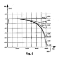
- Fig. 5 shows a graph of DASS suppression level in db 510 versus signal frequency 505 for five levels of DAAS aggressiveness 520, 525, 530, 535 and 540 according to an exemplary embodiment of the invention.
- Y is output
- X is input and C is the filter coefficient
- K is the level of attenuation (aggressiveness) calculated from desired Kdb (in dB)
- Fs is the sampling frequency
- BW is the filter Band Width
- Fp is the passing frequency.
- the graphs in fig. 5 show the different levels of aggressiveness effect with reference to the frequency axis when Fp is 2500 Hz.
- the first graph 520 describes a zero level aggressiveness, 0 db, which is a good approximation to the DAAS level when far-end is inactive.
- the level of DAAS aggressiveness is maximal 540 and in an exemplary embodiment of the invention the DAAS 249 suppression will be approximately -28 db at the highest frequency of 4000 Hz.
- both far-end and near-end are simultaneously active or at transition periods between maximal and zero aggressiveness - intermediate level of aggressiveness will be applied as shown in 525, 530 and 535.
- Section headings are provided for assistance in navigation and should not be considered as necessarily limiting the contents of the section.
Landscapes
- Engineering & Computer Science (AREA)
- Signal Processing (AREA)
- Cable Transmission Systems, Equalization Of Radio And Reduction Of Echo (AREA)
- Analogue/Digital Conversion (AREA)
Claims (11)
- Procédé de suppression de distorsion de repliement dans un système de téléphone à haut-parleur à sous-bande, le procédé comprenant les étapes qui consistent :a. à recevoir un signal audio analogique à partir d'une interface d'entrée audio analogique d'extrémité locale (286, 287) ;b. à convertir ledit signal audio analogique en un signal audio numérique d'extrémité locale en utilisant un A2D (273) ;c. à recevoir N ≥ 2 sous-bandes de données audio numériques décodées à partir d'une extrémité distante (206 ; 209),
à fusionner (230) lesdites N ≥ 2 sous-bandes de données audio numériques décodées en des données audio numériques décodées à large bande (WB) devant être converties par une unité D2A (270) et fournies à une interface de sortie audio analogique (280, 281) ;d. à diviser (233) ledit signal audio numérique d'extrémité locale en N ≥ 2 signaux audio numériques de sous-bande d'extrémité locale ; et soite. à soustraire (265) un signal numérique simulé de chacun desdits N ≥ 2 signaux audio numériques de sous-bande d'extrémité locale, où ledit signal numérique simulé est créé par une unité d'annulation d'écho (246) ; etf. à appliquer une suppression anti-distorsion de repliement dynamique, DAAS, avec une agressivité variable (249) sur chacun desdits N ≥ 2 signaux audio numériques de sous-bande d'extrémité locale soustraits, oue. à appliquer (249) une suppression anti-distorsion de repliement dynamique, DAAS, avec une agressivité variable sur chacun desdits N ≥ 2 signaux audio numériques de sous-bande d'extrémité locale ; etf. à soustraire (265) un signal numérique simulé de chacun desdits N ≥ 2 signaux audio numériques de sous-bande d'extrémité locale supprimés, où ledit signal numérique simulé est créé par une unité d'annulation d'écho (246),où ladite agressivité variable est sensible à l'activité de ladite extrémité distante (204) et à l'activité de ladite interface d'entrée audio analogique d'extrémité locale (286). - Procédé selon la revendication 1, dans lequel ladite agressivité variable est définie à un niveau maximal prédéfini (497) seulement lorsque ladite extrémité distante est active, à approximativement zéro (475) lorsque ladite extrémité distante est inactive et à des niveaux intermédiaires prédéfinis d'agressivité (480 ; 485 ; 490) lorsque à la fois ladite extrémité distante et ladite interface d'entrée audio analogique d'extrémité locale sont simultanément actives.
- Procédé selon la revendication 1, dans lequel ladite unité d'annulation d'écho (246) reçoit un signal qui est échantillonné à partir desdites sous-bandes de données audio numériques décodées (250) provenant d'une source audio d'extrémité distante (204) et supprimé par un suppresseur anti-distorsion de repliement, AAS, (243) qui est continuellement actif.
- Procédé selon la revendication 3, dans lequel le niveau de suppression dudit AAS (243) est approximativement égal à un niveau maximal dudit DAAS (249).
- Procédé selon la revendication 1, dans lequel N = 2 (208 ; 209).
- Procédé selon la revendication 1, dans lequel ladite division dudit signal audio numérique d'extrémité locale est effectuée par un QMF G722 (233).
- Procédé selon la revendication 1, dans lequel ladite interface d'entrée audio analogique d'extrémité locale est un microphone (286).
- Procédé selon la revendication 1, dans lequel ladite interface de sortie audio analogique est un haut-parleur (280).
- Procédé selon la revendication 1, dans lequel ladite unité d'annulation d'écho attribue éventuellement un nombre de coefficients différent.
- Procédé selon la revendication 1, dans lequel N=2 (206 ; 209) et dans lequel la division dudit signal audio numérique d'extrémité locale est effectuée par un QMF G722 (233) et dans lequel le nombre de coefficients attribués pour un annuleur d'écho Haute bande est inférieur au nombre de coefficients attribués pour un annuleur d'écho Basse bande.
- Système de téléphone à haut-parleur qui effectue une suppression anti-distorsion de repliement dynamique sur des signaux audio numériques de sous-bandes, le système comprend :a. N ≥ 2 décodeurs de sous-bandes (206 ; 209) configurés pour décoder des données audio numériques codées qui sont transmises par une source audio d'extrémité distante (204) ;b. un dispositif de combinaison (230) destiné à recevoir et à fusionner des données audio décodées qui sont transmises par lesdits N ≥ 2 décodeurs de sous-bandes (206 ; 209) ;c. un convertisseur numérique-analogique (270) configuré pour transformer la sortie provenant dudit dispositif de combinaison en un signal audio analogique et pour fournir le signal audio analogique à une interface de sortie audio analogique (280 ; 281) ;d. une interface d'entrée audio analogique d'extrémité locale (286 ; 287) configurée pour fournir un signal audio analogique qui est converti en un signal audio numérique par une unité A2D et divisé en N ≥ 2 sous-bandes de signal audio numérique ;e. N suppresseurs dynamiques anti-distorsion de repliement, DAAS, (249) où chacun desdits N ≥ 2 DAAS est configuré pour supprimer l'une desdites N sous-bandes de signal audio numérique en appliquant un niveau d'agressivité variable ;f. N unités de soustraction (265), chaque unité de soustraction étant configurée pour recevoir des sous-bandes supprimées de données audio numériques après avoir été supprimées par ledit DASS et pour soustraire un signal d'annulation d'écho qui est fourni par une unité d'annulation d'écho ; etg. N codeurs (212 ; 215), où chacun des codeurs est configuré pour recevoir et coder la sortie d'une unité de soustraction, où ladite agressivité variable est sensible à l'activité de ladite extrémité distante (204) et à l'activité de ladite interface de sortie audio analogique (286).
Applications Claiming Priority (2)
| Application Number | Priority Date | Filing Date | Title |
|---|---|---|---|
| US11/829,402 US8285554B2 (en) | 2007-07-27 | 2007-07-27 | Method and system for dynamic aliasing suppression |
| PCT/IL2008/001014 WO2009016616A2 (fr) | 2007-07-27 | 2008-07-23 | Procédé et système pour une suppression dynamique de la distorsion de repliement |
Publications (3)
| Publication Number | Publication Date |
|---|---|
| EP2174236A2 EP2174236A2 (fr) | 2010-04-14 |
| EP2174236A4 EP2174236A4 (fr) | 2010-09-08 |
| EP2174236B1 true EP2174236B1 (fr) | 2013-12-04 |
Family
ID=40296081
Family Applications (1)
| Application Number | Title | Priority Date | Filing Date |
|---|---|---|---|
| EP08789700.5A Not-in-force EP2174236B1 (fr) | 2007-07-27 | 2008-07-23 | Procédé et système pour une suppression dynamique de la distorsion de repliement |
Country Status (3)
| Country | Link |
|---|---|
| US (1) | US8285554B2 (fr) |
| EP (1) | EP2174236B1 (fr) |
| WO (1) | WO2009016616A2 (fr) |
Families Citing this family (33)
| Publication number | Priority date | Publication date | Assignee | Title |
|---|---|---|---|---|
| US8026386B2 (en) * | 2007-08-10 | 2011-09-27 | Genomatica, Inc. | Methods for the synthesis of olefins and derivatives |
| CA2712779C (fr) * | 2008-01-22 | 2021-03-16 | Genomatica, Inc. | Methodes et organismes destines a l'utilisation de gaz de synthese ou d'autres sources gazeuses de carbone et de methanol |
| DK2262901T3 (en) * | 2008-03-05 | 2019-01-21 | Genomatica Inc | ORGANISMS PRODUCING PRIMARY ALCOHOL |
| ES2656790T3 (es) * | 2008-03-27 | 2018-02-28 | Genomatica, Inc. | Microorganismos para la producción de ácido adípico y otros compuestos |
| BRPI0913901A2 (pt) * | 2008-06-17 | 2016-12-13 | Genomatica Inc | micro-organismos e métodos para a biossíntese de fumarato, malato e acrilato |
| EP2483401B1 (fr) | 2009-09-29 | 2017-06-21 | Butamax (TM) Advanced Biofuels LLC | Cellules hôtes à production améliorée de levure |
| JP5424936B2 (ja) * | 2010-02-24 | 2014-02-26 | パナソニック株式会社 | 通信端末及び通信方法 |
| DE112012006266B4 (de) * | 2012-04-25 | 2017-10-12 | Mitsubishi Electric Corporation | Echolöschvorrichtung |
| TWI459753B (zh) * | 2012-07-31 | 2014-11-01 | Pegatron Corp | 網路音訊測試系統及其網路音訊測試之方法 |
| JP6008252B2 (ja) * | 2013-08-23 | 2016-10-19 | 住友電装株式会社 | コネクタ |
| US9554207B2 (en) | 2015-04-30 | 2017-01-24 | Shure Acquisition Holdings, Inc. | Offset cartridge microphones |
| US9565493B2 (en) | 2015-04-30 | 2017-02-07 | Shure Acquisition Holdings, Inc. | Array microphone system and method of assembling the same |
| US10367948B2 (en) | 2017-01-13 | 2019-07-30 | Shure Acquisition Holdings, Inc. | Post-mixing acoustic echo cancellation systems and methods |
| CN112335261B (zh) | 2018-06-01 | 2023-07-18 | 舒尔获得控股公司 | 图案形成麦克风阵列 |
| US11297423B2 (en) | 2018-06-15 | 2022-04-05 | Shure Acquisition Holdings, Inc. | Endfire linear array microphone |
| US11310596B2 (en) | 2018-09-20 | 2022-04-19 | Shure Acquisition Holdings, Inc. | Adjustable lobe shape for array microphones |
| US11303981B2 (en) | 2019-03-21 | 2022-04-12 | Shure Acquisition Holdings, Inc. | Housings and associated design features for ceiling array microphones |
| JP7572964B2 (ja) | 2019-03-21 | 2024-10-24 | シュアー アクイジッション ホールディングス インコーポレイテッド | 阻止機能を伴うビーム形成マイクロフォンローブの自動集束、領域内自動集束、および自動配置 |
| US11558693B2 (en) | 2019-03-21 | 2023-01-17 | Shure Acquisition Holdings, Inc. | Auto focus, auto focus within regions, and auto placement of beamformed microphone lobes with inhibition and voice activity detection functionality |
| TW202101422A (zh) | 2019-05-23 | 2021-01-01 | 美商舒爾獲得控股公司 | 可操縱揚聲器陣列、系統及其方法 |
| WO2020243471A1 (fr) | 2019-05-31 | 2020-12-03 | Shure Acquisition Holdings, Inc. | Automélangeur à faible latence, à détection d'activité vocale et de bruit intégrée |
| CN114467312A (zh) | 2019-08-23 | 2022-05-10 | 舒尔获得控股公司 | 具有改进方向性的二维麦克风阵列 |
| US12028678B2 (en) | 2019-11-01 | 2024-07-02 | Shure Acquisition Holdings, Inc. | Proximity microphone |
| US11552611B2 (en) | 2020-02-07 | 2023-01-10 | Shure Acquisition Holdings, Inc. | System and method for automatic adjustment of reference gain |
| USD944776S1 (en) | 2020-05-05 | 2022-03-01 | Shure Acquisition Holdings, Inc. | Audio device |
| US11706562B2 (en) | 2020-05-29 | 2023-07-18 | Shure Acquisition Holdings, Inc. | Transducer steering and configuration systems and methods using a local positioning system |
| JP7814400B2 (ja) | 2021-01-28 | 2026-02-16 | シュアー アクイジッション ホールディングス インコーポレイテッド | ハイブリッドオーディオビーム形成システム |
| US12452584B2 (en) | 2021-01-29 | 2025-10-21 | Shure Acquisition Holdings, Inc. | Scalable conferencing systems and methods |
| US12542123B2 (en) | 2021-08-31 | 2026-02-03 | Shure Acquisition Holdings, Inc. | Mask non-linear processor for acoustic echo cancellation |
| US12289584B2 (en) | 2021-10-04 | 2025-04-29 | Shure Acquisition Holdings, Inc. | Networked automixer systems and methods |
| EP4427465A1 (fr) | 2021-11-05 | 2024-09-11 | Shure Acquisition Holdings, Inc. | Algorithme distribué pour auto-mélange de la parole sur des réseaux sans fil |
| US12250526B2 (en) | 2022-01-07 | 2025-03-11 | Shure Acquisition Holdings, Inc. | Audio beamforming with nulling control system and methods |
| US12598261B2 (en) | 2022-09-28 | 2026-04-07 | Shure Acquisition Holdings, Inc. | Wideband doubletalk detection for optimization of acoustic echo cancellation |
Citations (2)
| Publication number | Priority date | Publication date | Assignee | Title |
|---|---|---|---|---|
| US5500880A (en) * | 1992-08-18 | 1996-03-19 | U.S. Philips Corporation | Transmission system comprising a sub-band echo canceller which includes a sub-band coding arrangement |
| WO2007008086A1 (fr) * | 2005-07-13 | 2007-01-18 | Tandberg Telecom As | Procede et systeme de suppression d'echo a faible delai |
Family Cites Families (9)
| Publication number | Priority date | Publication date | Assignee | Title |
|---|---|---|---|---|
| US5956674A (en) * | 1995-12-01 | 1999-09-21 | Digital Theater Systems, Inc. | Multi-channel predictive subband audio coder using psychoacoustic adaptive bit allocation in frequency, time and over the multiple channels |
| US6049517A (en) * | 1996-04-30 | 2000-04-11 | Sony Corporation | Dual format audio signal compression |
| US6154158A (en) * | 1998-06-30 | 2000-11-28 | Qualcomm Incorporated | Digital-to-analog converter D.C. offset correction comparing converter input and output signals |
| GB2344036B (en) * | 1998-11-23 | 2004-01-21 | Mitel Corp | Single-sided subband filters |
| US6628781B1 (en) * | 1999-06-03 | 2003-09-30 | Telefonaktiebolaget Lm Ericsson (Publ) | Methods and apparatus for improved sub-band adaptive filtering in echo cancellation systems |
| US20070078645A1 (en) * | 2005-09-30 | 2007-04-05 | Nokia Corporation | Filterbank-based processing of speech signals |
| US7212139B1 (en) * | 2005-11-15 | 2007-05-01 | Texas Instruments Incorporated | System for suppressing aliasing interferers in decimating and sub-sampling systems |
| US20080059201A1 (en) * | 2006-09-03 | 2008-03-06 | Chih-Hsiang Hsiao | Method and Related Device for Improving the Processing of MP3 Decoding and Encoding |
| US8155304B2 (en) * | 2007-04-10 | 2012-04-10 | Microsoft Corporation | Filter bank optimization for acoustic echo cancellation |
-
2007
- 2007-07-27 US US11/829,402 patent/US8285554B2/en not_active Expired - Fee Related
-
2008
- 2008-07-23 WO PCT/IL2008/001014 patent/WO2009016616A2/fr not_active Ceased
- 2008-07-23 EP EP08789700.5A patent/EP2174236B1/fr not_active Not-in-force
Patent Citations (2)
| Publication number | Priority date | Publication date | Assignee | Title |
|---|---|---|---|---|
| US5500880A (en) * | 1992-08-18 | 1996-03-19 | U.S. Philips Corporation | Transmission system comprising a sub-band echo canceller which includes a sub-band coding arrangement |
| WO2007008086A1 (fr) * | 2005-07-13 | 2007-01-18 | Tandberg Telecom As | Procede et systeme de suppression d'echo a faible delai |
Also Published As
| Publication number | Publication date |
|---|---|
| EP2174236A4 (fr) | 2010-09-08 |
| US20090030536A1 (en) | 2009-01-29 |
| EP2174236A2 (fr) | 2010-04-14 |
| WO2009016616A2 (fr) | 2009-02-05 |
| US8285554B2 (en) | 2012-10-09 |
| WO2009016616A3 (fr) | 2010-03-04 |
Similar Documents
| Publication | Publication Date | Title |
|---|---|---|
| EP2174236B1 (fr) | Procédé et système pour une suppression dynamique de la distorsion de repliement | |
| US8923509B2 (en) | Controlling echo in a wideband voice conference | |
| EP1298815B1 (fr) | Processeur d'écho avec un générateur de pseudo-bruit de fond | |
| US4712235A (en) | Method and apparatus for improved control and time sharing of an echo canceller | |
| CN100521710C (zh) | 处理能力要求降低的回波消除器 | |
| US20080159551A1 (en) | System and Method for Acoustic Echo Removal (AER) | |
| CN101878637B (zh) | 用于对语音信号进行回声消除的方法和配置 | |
| KR101445999B1 (ko) | 광대역 음성 신호용 계산 절감 에코 소거기 | |
| JP4457639B2 (ja) | エコーキャンセラ | |
| KR20130040194A (ko) | 잔류 에코를 억제하는 방법 및 장치 | |
| CN101923862A (zh) | 使用自适应滤波器处理子带信号的方法和系统 | |
| GB2448201A (en) | Cancelling non-linear echo during full duplex communication in a hands free communication system. | |
| US7243065B2 (en) | Low-complexity comfort noise generator | |
| JP4410819B2 (ja) | エコーキャンセラ | |
| EP2622834A1 (fr) | Optimisation de réduction de l'écho | |
| KR100842590B1 (ko) | 이동 단말에서 음향 반향 제거 방법 및 장치 | |
| US20090067615A1 (en) | Echo cancellation using gain control | |
| US8369511B2 (en) | Robust method of echo suppressor | |
| US8194850B2 (en) | Method and apparatus for voice communication | |
| EP2568619B1 (fr) | Codec d'annulation d'écho | |
| JP4877083B2 (ja) | 残留エコー抑圧制御装置、方法及びプログラム | |
| JPH0795711B2 (ja) | 反響信号消去装置 | |
| JP4383416B2 (ja) | ハウリング防止方法、装置、プログラム、及びこのプログラムを記録した記録媒体 | |
| JP4551275B2 (ja) | ハウリング防止方法、その装置、そのプログラムおよびその記録媒体 | |
| Sudo et al. | Spectrum selective nonlinear echo suppression based on the amount of linear echo cancellation |
Legal Events
| Date | Code | Title | Description |
|---|---|---|---|
| PUAI | Public reference made under article 153(3) epc to a published international application that has entered the european phase |
Free format text: ORIGINAL CODE: 0009012 |
|
| 17P | Request for examination filed |
Effective date: 20100106 |
|
| AK | Designated contracting states |
Kind code of ref document: A2 Designated state(s): AT BE BG CH CY CZ DE DK EE ES FI FR GB GR HR HU IE IS IT LI LT LU LV MC MT NL NO PL PT RO SE SI SK TR |
|
| AX | Request for extension of the european patent |
Extension state: AL BA MK RS |
|
| RIC1 | Information provided on ipc code assigned before grant |
Ipc: H03M 1/06 20060101AFI20100518BHEP |
|
| A4 | Supplementary search report drawn up and despatched |
Effective date: 20100811 |
|
| DAX | Request for extension of the european patent (deleted) | ||
| 17Q | First examination report despatched |
Effective date: 20130124 |
|
| REG | Reference to a national code |
Ref country code: DE Ref legal event code: R079 Ref document number: 602008029121 Country of ref document: DE Free format text: PREVIOUS MAIN CLASS: G06F0017000000 Ipc: H04M0009080000 |
|
| RIC1 | Information provided on ipc code assigned before grant |
Ipc: H04M 9/08 20060101AFI20130517BHEP |
|
| GRAP | Despatch of communication of intention to grant a patent |
Free format text: ORIGINAL CODE: EPIDOSNIGR1 |
|
| INTG | Intention to grant announced |
Effective date: 20130628 |
|
| GRAS | Grant fee paid |
Free format text: ORIGINAL CODE: EPIDOSNIGR3 |
|
| GRAA | (expected) grant |
Free format text: ORIGINAL CODE: 0009210 |
|
| AK | Designated contracting states |
Kind code of ref document: B1 Designated state(s): AT BE BG CH CY CZ DE DK EE ES FI FR GB GR HR HU IE IS IT LI LT LU LV MC MT NL NO PL PT RO SE SI SK TR |
|
| REG | Reference to a national code |
Ref country code: GB Ref legal event code: FG4D |
|
| REG | Reference to a national code |
Ref country code: CH Ref legal event code: EP |
|
| REG | Reference to a national code |
Ref country code: IE Ref legal event code: FG4D Ref country code: AT Ref legal event code: REF Ref document number: 643925 Country of ref document: AT Kind code of ref document: T Effective date: 20140115 |
|
| REG | Reference to a national code |
Ref country code: DE Ref legal event code: R096 Ref document number: 602008029121 Country of ref document: DE Effective date: 20140206 |
|
| REG | Reference to a national code |
Ref country code: NL Ref legal event code: VDEP Effective date: 20131204 |
|
| REG | Reference to a national code |
Ref country code: AT Ref legal event code: MK05 Ref document number: 643925 Country of ref document: AT Kind code of ref document: T Effective date: 20131204 |
|
| PG25 | Lapsed in a contracting state [announced via postgrant information from national office to epo] |
Ref country code: NL Free format text: LAPSE BECAUSE OF FAILURE TO SUBMIT A TRANSLATION OF THE DESCRIPTION OR TO PAY THE FEE WITHIN THE PRESCRIBED TIME-LIMIT Effective date: 20131204 Ref country code: LT Free format text: LAPSE BECAUSE OF FAILURE TO SUBMIT A TRANSLATION OF THE DESCRIPTION OR TO PAY THE FEE WITHIN THE PRESCRIBED TIME-LIMIT Effective date: 20131204 Ref country code: FI Free format text: LAPSE BECAUSE OF FAILURE TO SUBMIT A TRANSLATION OF THE DESCRIPTION OR TO PAY THE FEE WITHIN THE PRESCRIBED TIME-LIMIT Effective date: 20131204 Ref country code: SE Free format text: LAPSE BECAUSE OF FAILURE TO SUBMIT A TRANSLATION OF THE DESCRIPTION OR TO PAY THE FEE WITHIN THE PRESCRIBED TIME-LIMIT Effective date: 20131204 Ref country code: NO Free format text: LAPSE BECAUSE OF FAILURE TO SUBMIT A TRANSLATION OF THE DESCRIPTION OR TO PAY THE FEE WITHIN THE PRESCRIBED TIME-LIMIT Effective date: 20140304 Ref country code: HR Free format text: LAPSE BECAUSE OF FAILURE TO SUBMIT A TRANSLATION OF THE DESCRIPTION OR TO PAY THE FEE WITHIN THE PRESCRIBED TIME-LIMIT Effective date: 20131204 |
|
| REG | Reference to a national code |
Ref country code: LT Ref legal event code: MG4D |
|
| PG25 | Lapsed in a contracting state [announced via postgrant information from national office to epo] |
Ref country code: AT Free format text: LAPSE BECAUSE OF FAILURE TO SUBMIT A TRANSLATION OF THE DESCRIPTION OR TO PAY THE FEE WITHIN THE PRESCRIBED TIME-LIMIT Effective date: 20131204 Ref country code: CY Free format text: LAPSE BECAUSE OF FAILURE TO SUBMIT A TRANSLATION OF THE DESCRIPTION OR TO PAY THE FEE WITHIN THE PRESCRIBED TIME-LIMIT Effective date: 20131204 Ref country code: LV Free format text: LAPSE BECAUSE OF FAILURE TO SUBMIT A TRANSLATION OF THE DESCRIPTION OR TO PAY THE FEE WITHIN THE PRESCRIBED TIME-LIMIT Effective date: 20131204 |
|
| PG25 | Lapsed in a contracting state [announced via postgrant information from national office to epo] |
Ref country code: EE Free format text: LAPSE BECAUSE OF FAILURE TO SUBMIT A TRANSLATION OF THE DESCRIPTION OR TO PAY THE FEE WITHIN THE PRESCRIBED TIME-LIMIT Effective date: 20131204 Ref country code: BE Free format text: LAPSE BECAUSE OF FAILURE TO SUBMIT A TRANSLATION OF THE DESCRIPTION OR TO PAY THE FEE WITHIN THE PRESCRIBED TIME-LIMIT Effective date: 20131204 Ref country code: IS Free format text: LAPSE BECAUSE OF FAILURE TO SUBMIT A TRANSLATION OF THE DESCRIPTION OR TO PAY THE FEE WITHIN THE PRESCRIBED TIME-LIMIT Effective date: 20140404 |
|
| PG25 | Lapsed in a contracting state [announced via postgrant information from national office to epo] |
Ref country code: CZ Free format text: LAPSE BECAUSE OF FAILURE TO SUBMIT A TRANSLATION OF THE DESCRIPTION OR TO PAY THE FEE WITHIN THE PRESCRIBED TIME-LIMIT Effective date: 20131204 Ref country code: PL Free format text: LAPSE BECAUSE OF FAILURE TO SUBMIT A TRANSLATION OF THE DESCRIPTION OR TO PAY THE FEE WITHIN THE PRESCRIBED TIME-LIMIT Effective date: 20131204 Ref country code: RO Free format text: LAPSE BECAUSE OF FAILURE TO SUBMIT A TRANSLATION OF THE DESCRIPTION OR TO PAY THE FEE WITHIN THE PRESCRIBED TIME-LIMIT Effective date: 20131204 Ref country code: PT Free format text: LAPSE BECAUSE OF FAILURE TO SUBMIT A TRANSLATION OF THE DESCRIPTION OR TO PAY THE FEE WITHIN THE PRESCRIBED TIME-LIMIT Effective date: 20140404 Ref country code: ES Free format text: LAPSE BECAUSE OF FAILURE TO SUBMIT A TRANSLATION OF THE DESCRIPTION OR TO PAY THE FEE WITHIN THE PRESCRIBED TIME-LIMIT Effective date: 20131204 Ref country code: SK Free format text: LAPSE BECAUSE OF FAILURE TO SUBMIT A TRANSLATION OF THE DESCRIPTION OR TO PAY THE FEE WITHIN THE PRESCRIBED TIME-LIMIT Effective date: 20131204 |
|
| REG | Reference to a national code |
Ref country code: DE Ref legal event code: R097 Ref document number: 602008029121 Country of ref document: DE |
|
| PLBE | No opposition filed within time limit |
Free format text: ORIGINAL CODE: 0009261 |
|
| STAA | Information on the status of an ep patent application or granted ep patent |
Free format text: STATUS: NO OPPOSITION FILED WITHIN TIME LIMIT |
|
| PG25 | Lapsed in a contracting state [announced via postgrant information from national office to epo] |
Ref country code: DK Free format text: LAPSE BECAUSE OF FAILURE TO SUBMIT A TRANSLATION OF THE DESCRIPTION OR TO PAY THE FEE WITHIN THE PRESCRIBED TIME-LIMIT Effective date: 20131204 |
|
| 26N | No opposition filed |
Effective date: 20140905 |
|
| REG | Reference to a national code |
Ref country code: DE Ref legal event code: R097 Ref document number: 602008029121 Country of ref document: DE Effective date: 20140905 |
|
| PG25 | Lapsed in a contracting state [announced via postgrant information from national office to epo] |
Ref country code: SI Free format text: LAPSE BECAUSE OF FAILURE TO SUBMIT A TRANSLATION OF THE DESCRIPTION OR TO PAY THE FEE WITHIN THE PRESCRIBED TIME-LIMIT Effective date: 20131204 Ref country code: LU Free format text: LAPSE BECAUSE OF FAILURE TO SUBMIT A TRANSLATION OF THE DESCRIPTION OR TO PAY THE FEE WITHIN THE PRESCRIBED TIME-LIMIT Effective date: 20140723 |
|
| REG | Reference to a national code |
Ref country code: CH Ref legal event code: PL |
|
| GBPC | Gb: european patent ceased through non-payment of renewal fee |
Effective date: 20140723 |
|
| REG | Reference to a national code |
Ref country code: IE Ref legal event code: MM4A |
|
| REG | Reference to a national code |
Ref country code: FR Ref legal event code: ST Effective date: 20150331 |
|
| PG25 | Lapsed in a contracting state [announced via postgrant information from national office to epo] |
Ref country code: IT Free format text: LAPSE BECAUSE OF FAILURE TO SUBMIT A TRANSLATION OF THE DESCRIPTION OR TO PAY THE FEE WITHIN THE PRESCRIBED TIME-LIMIT Effective date: 20131204 Ref country code: LI Free format text: LAPSE BECAUSE OF NON-PAYMENT OF DUE FEES Effective date: 20140731 Ref country code: CH Free format text: LAPSE BECAUSE OF NON-PAYMENT OF DUE FEES Effective date: 20140731 |
|
| PG25 | Lapsed in a contracting state [announced via postgrant information from national office to epo] |
Ref country code: FR Free format text: LAPSE BECAUSE OF NON-PAYMENT OF DUE FEES Effective date: 20140731 Ref country code: GB Free format text: LAPSE BECAUSE OF NON-PAYMENT OF DUE FEES Effective date: 20140723 |
|
| PG25 | Lapsed in a contracting state [announced via postgrant information from national office to epo] |
Ref country code: IE Free format text: LAPSE BECAUSE OF NON-PAYMENT OF DUE FEES Effective date: 20140723 |
|
| PG25 | Lapsed in a contracting state [announced via postgrant information from national office to epo] |
Ref country code: MC Free format text: LAPSE BECAUSE OF FAILURE TO SUBMIT A TRANSLATION OF THE DESCRIPTION OR TO PAY THE FEE WITHIN THE PRESCRIBED TIME-LIMIT Effective date: 20131204 |
|
| PG25 | Lapsed in a contracting state [announced via postgrant information from national office to epo] |
Ref country code: BG Free format text: LAPSE BECAUSE OF FAILURE TO SUBMIT A TRANSLATION OF THE DESCRIPTION OR TO PAY THE FEE WITHIN THE PRESCRIBED TIME-LIMIT Effective date: 20131204 |
|
| PG25 | Lapsed in a contracting state [announced via postgrant information from national office to epo] |
Ref country code: MT Free format text: LAPSE BECAUSE OF FAILURE TO SUBMIT A TRANSLATION OF THE DESCRIPTION OR TO PAY THE FEE WITHIN THE PRESCRIBED TIME-LIMIT Effective date: 20131204 Ref country code: GR Free format text: LAPSE BECAUSE OF FAILURE TO SUBMIT A TRANSLATION OF THE DESCRIPTION OR TO PAY THE FEE WITHIN THE PRESCRIBED TIME-LIMIT Effective date: 20140305 |
|
| PG25 | Lapsed in a contracting state [announced via postgrant information from national office to epo] |
Ref country code: TR Free format text: LAPSE BECAUSE OF FAILURE TO SUBMIT A TRANSLATION OF THE DESCRIPTION OR TO PAY THE FEE WITHIN THE PRESCRIBED TIME-LIMIT Effective date: 20131204 Ref country code: HU Free format text: LAPSE BECAUSE OF FAILURE TO SUBMIT A TRANSLATION OF THE DESCRIPTION OR TO PAY THE FEE WITHIN THE PRESCRIBED TIME-LIMIT; INVALID AB INITIO Effective date: 20080723 |
|
| PGFP | Annual fee paid to national office [announced via postgrant information from national office to epo] |
Ref country code: DE Payment date: 20240619 Year of fee payment: 17 |
|
| REG | Reference to a national code |
Ref country code: DE Ref legal event code: R119 Ref document number: 602008029121 Country of ref document: DE |
|
| PG25 | Lapsed in a contracting state [announced via postgrant information from national office to epo] |
Ref country code: DE Free format text: LAPSE BECAUSE OF NON-PAYMENT OF DUE FEES Effective date: 20260203 |