EP2175179A1 - Dispositif d'étanchéité - Google Patents
Dispositif d'étanchéité Download PDFInfo
- Publication number
- EP2175179A1 EP2175179A1 EP08792186A EP08792186A EP2175179A1 EP 2175179 A1 EP2175179 A1 EP 2175179A1 EP 08792186 A EP08792186 A EP 08792186A EP 08792186 A EP08792186 A EP 08792186A EP 2175179 A1 EP2175179 A1 EP 2175179A1
- Authority
- EP
- European Patent Office
- Prior art keywords
- lip
- sleeve
- flange
- sealing device
- slinger
- Prior art date
- Legal status (The legal status is an assumption and is not a legal conclusion. Google has not performed a legal analysis and makes no representation as to the accuracy of the status listed.)
- Withdrawn
Links
Images


Classifications
-
- F—MECHANICAL ENGINEERING; LIGHTING; HEATING; WEAPONS; BLASTING
- F16—ENGINEERING ELEMENTS AND UNITS; GENERAL MEASURES FOR PRODUCING AND MAINTAINING EFFECTIVE FUNCTIONING OF MACHINES OR INSTALLATIONS; THERMAL INSULATION IN GENERAL
- F16J—PISTONS; CYLINDERS; SEALINGS
- F16J15/00—Sealings
- F16J15/16—Sealings between relatively-moving surfaces
- F16J15/32—Sealings between relatively-moving surfaces with elastic sealings, e.g. O-rings
- F16J15/3248—Sealings between relatively-moving surfaces with elastic sealings, e.g. O-rings provided with casings or supports
- F16J15/3252—Sealings between relatively-moving surfaces with elastic sealings, e.g. O-rings provided with casings or supports with rigid casings or supports
- F16J15/3256—Sealings between relatively-moving surfaces with elastic sealings, e.g. O-rings provided with casings or supports with rigid casings or supports comprising two casing or support elements, one attached to each surface, e.g. cartridge or cassette seals
- F16J15/3264—Sealings between relatively-moving surfaces with elastic sealings, e.g. O-rings provided with casings or supports with rigid casings or supports comprising two casing or support elements, one attached to each surface, e.g. cartridge or cassette seals the elements being separable from each other
-
- F—MECHANICAL ENGINEERING; LIGHTING; HEATING; WEAPONS; BLASTING
- F16—ENGINEERING ELEMENTS AND UNITS; GENERAL MEASURES FOR PRODUCING AND MAINTAINING EFFECTIVE FUNCTIONING OF MACHINES OR INSTALLATIONS; THERMAL INSULATION IN GENERAL
- F16J—PISTONS; CYLINDERS; SEALINGS
- F16J15/00—Sealings
- F16J15/16—Sealings between relatively-moving surfaces
- F16J15/164—Sealings between relatively-moving surfaces the sealing action depending on movements; pressure difference, temperature or presence of leaking fluid
-
- F—MECHANICAL ENGINEERING; LIGHTING; HEATING; WEAPONS; BLASTING
- F16—ENGINEERING ELEMENTS AND UNITS; GENERAL MEASURES FOR PRODUCING AND MAINTAINING EFFECTIVE FUNCTIONING OF MACHINES OR INSTALLATIONS; THERMAL INSULATION IN GENERAL
- F16C—SHAFTS; FLEXIBLE SHAFTS; ELEMENTS OR CRANKSHAFT MECHANISMS; ROTARY BODIES OTHER THAN GEARING ELEMENTS; BEARINGS
- F16C2300/00—Application independent of particular apparatuses
- F16C2300/02—General use or purpose, i.e. no use, purpose, special adaptation or modification indicated or a wide variety of uses mentioned
-
- F—MECHANICAL ENGINEERING; LIGHTING; HEATING; WEAPONS; BLASTING
- F16—ENGINEERING ELEMENTS AND UNITS; GENERAL MEASURES FOR PRODUCING AND MAINTAINING EFFECTIVE FUNCTIONING OF MACHINES OR INSTALLATIONS; THERMAL INSULATION IN GENERAL
- F16C—SHAFTS; FLEXIBLE SHAFTS; ELEMENTS OR CRANKSHAFT MECHANISMS; ROTARY BODIES OTHER THAN GEARING ELEMENTS; BEARINGS
- F16C33/00—Parts of bearings; Special methods for making bearings or parts thereof
- F16C33/72—Sealings
- F16C33/76—Sealings of ball or roller bearings
- F16C33/78—Sealings of ball or roller bearings with a diaphragm, disc, or ring, with or without resilient members
- F16C33/7816—Details of the sealing or parts thereof, e.g. geometry, material
- F16C33/782—Details of the sealing or parts thereof, e.g. geometry, material of the sealing region
- F16C33/7826—Details of the sealing or parts thereof, e.g. geometry, material of the sealing region of the opposing surface cooperating with the seal, e.g. a shoulder surface of a bearing ring
-
- F—MECHANICAL ENGINEERING; LIGHTING; HEATING; WEAPONS; BLASTING
- F16—ENGINEERING ELEMENTS AND UNITS; GENERAL MEASURES FOR PRODUCING AND MAINTAINING EFFECTIVE FUNCTIONING OF MACHINES OR INSTALLATIONS; THERMAL INSULATION IN GENERAL
- F16C—SHAFTS; FLEXIBLE SHAFTS; ELEMENTS OR CRANKSHAFT MECHANISMS; ROTARY BODIES OTHER THAN GEARING ELEMENTS; BEARINGS
- F16C33/00—Parts of bearings; Special methods for making bearings or parts thereof
- F16C33/72—Sealings
- F16C33/76—Sealings of ball or roller bearings
- F16C33/78—Sealings of ball or roller bearings with a diaphragm, disc, or ring, with or without resilient members
- F16C33/7869—Sealings of ball or roller bearings with a diaphragm, disc, or ring, with or without resilient members mounted with a cylindrical portion to the inner surface of the outer race and having a radial portion extending inward
- F16C33/7879—Sealings of ball or roller bearings with a diaphragm, disc, or ring, with or without resilient members mounted with a cylindrical portion to the inner surface of the outer race and having a radial portion extending inward with a further sealing ring
- F16C33/7883—Sealings of ball or roller bearings with a diaphragm, disc, or ring, with or without resilient members mounted with a cylindrical portion to the inner surface of the outer race and having a radial portion extending inward with a further sealing ring mounted to the inner race and of generally L-shape, the two sealing rings defining a sealing with box-shaped cross-section
Definitions
- the present invention relates to a sealing device preventing dust, muddy water, etc. from an intrusion into a bearing or the like, and more particularly to a sealing device perfoming sealing by a throw off effect of a slinger.
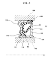
- FIG. 4 is a half cross sectional view illustrating a typical prior art of this kind of sealing device by cutting along a plane passing through an axis O.
- This sealing device is provided, for example, with a stationary sealing element 110 installed to an inner periphery of a non-rotating outer ring 101 in a bearing 100, and a metal slinger 120 having a sleeve 121 fitted to an outer periphery of an inner ring 102, which is a rotation side in the bearing 100, and a flange 122 extending from one end of the sleeve 121.
- a thrust lip 111 provided in the stationary sealing element 110 is made to be in intimate slidable contact with the flange 122 of the slinger 120, and a radial lip 112 provided in the stationary sealing element 110 so as to be positioned on an inner peripheral side of the thrust lip 111 is made to be intimate slidable contact with an outer peripheral surface of the sleeve 121 of the slinger 120.
- reference numeral 113 denotes a grease lip for holding a grease (not illustrated) for lubricating an inner portion of the bearing 100.
- this kind of sealing device is configured to prevent dust, muddy water, etc. from an intrusion from an external space A, by a throw off effect caused by a centrifugal force of the flange 122 integrally rotating with the inner ring 102, in an intimate contact slide section S1 between the flange 122 of the slinger 120 and the thrust lip 111. Further, even when dust, muddy water,etc. slightly passes from the intimate contact slide section S1 to the inner peripheral side thereof, the dust, the muddy water, etc.
- the present invention is made by considering the points mentioned above, and a technical object of the present invention is to prevent an abrasion due to an intervention of dust, muddy water, etc. into an intimate contact slide section and reduction of a sealing performance caused thereby, in a sealing device performing sealing by a throw off effect of a slinger.
- a sealing device includes:
- the sealing device further includes a dam provided on an outer peripheral surface of the sleeve, where the dam is positioned more on the flange side than an intimate contact slide section of the radial lip, and is continuous in a circumferential direction.
- the dam is a ridge, a groove, or a step which is relatively higher in a diametrical direction in an intimate contact slide section side of the radial lip.
- the dam is provided on the outer peripheral surface of the sleeve in the slinger, where the dam is positioned more on the flange side than the intimate contact slide section of the radial lip, and is continuous in the circumferential direction, even if a part of dust or muddy water to be sealed passes from the intimate contact slide section between the flange of the slinger and the thrust lip to its inner peripheral side, the dust, the muddy water, etc. are dammed by the dam, so that these can not intervene the intimate contact slide section between the sleeve and the radial lip. Further, the dust, the muddy water, etc. are discharged to the outer peripheral side of the thrust lip by a throw off effect of the flange. Accordingly, it is possible to effectively prevent an early abrasion of the intimate contact slide section between the sleeve and the radial lip, and a deterioration of a sealing performance generated thereby.
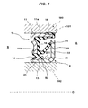
- Fig. 1 is a half cross sectional view illustrating a first embodiment of a sealing device in accordance with the present invention by cutting along a plane passing through an axis O.
- the sealing device in accordance with the first embodiment illustrated in Fig. 1 includes a stationary sealing element 1 attached to an inner periphery of an outer ring 101 of a bearing 100, and a slinger 2 attached to an outer periphery of an inner ring 102 of the bearing 100.
- the outer ring 101 corresponds to a stationary member described in claim 1
- the inner ring 102 corresponds to a rotary member described in claim 1.
- the stationary sealing element 1 includes a metal attaching ring 11, and a thrust lip 12, a radial lip 13, and a grease lip 14 which are integrally formed by a rubber-like elastic material in this attaching ring 11.
- the attaching ring 11 includes a cylindrical outer peripheral pressure insertion portion 11a which is pressed in and fitted to an inner peripheral surface of the outer ring 101 of the bearing 100, and an inward flange 11b which extends from an end portion of a bearing inner portion B side of the outer peripheral pressure insertion portion 11a to an inner peripheral side.
- the thrust lip 12 extends so as to form a conical tubular shape in which a leading end becomes larger in diameter toward an external space A, from a base portion elastic layer 15 which is made of a rubber-like elastic material and formed on the inward flange 11b of the attaching ring 11.
- the radial lip 13 is positioned in an inner peripheral side of the thrust lip 12 and extends so as to form a conical tubular shape in which a leading end becomes smaller in diameter toward the external space A from an inner peripheral end portion of the base portion elastic layer 15.
- the grease lip 14 is positioned more on the bearing inner portion B side than the radial lip 13, and extends so as to form a conical tubular shape in which a leading end becomes smaller in diameter toward a bearing inner portion B side.
- a part of the base portion elastic layer 15 goes around an end surface outer peripheral portion directed to the external space A side of the outer peripheral pressure insertion portion 11a in the attaching ring 11, and forms an outer peripheral seal portion 16 made to be in intimate contact with an inner peripheral surface of the outer ring 101.
- the slinger 2 is manufactured by press working a metal plate, or the like, and has a sleeve 21 which is pressed in and fitted to an outer peripheral surface of the inner ring 102 of the bearing 100, and a flange 22 which extends like a disc shape to an outer peripheral side from an end portion of the bearing external space A side of the sleeve 21.
- the thrust lip 12 in the stationary sealing element 1 is structured such that a whole periphery in a leading end portion comes to be in intimate slidable contact with an inner side surface of the flange 22 in the slinger 2, thereby configuring an intimate contact slide section S1.
- the radial lip 13 is structured such that a whole periphery of an inner peripheral edge portion in the vicinity of a leading end comes to be in intimate slidable contact with an outer peripheral surface of the sleeve 21 in the slinger 2, thereby configuring an intimate contact slide section S2.
- a dam 23 is provided at an outer peripheral surface of the sleeve 21 in the slinger 2.
- the dam is positioned more on the flange 22 side than the intimate contact slide section S2 of the radial lip 13, and formed by a ridge 231 being continuous in a circumferential direction.
- the sealing device in accordance with the first embodiment configured as mentioned above is structured so as to prevent dust, muddy water, etc. coming flying from the external space A and invading by a throw off effect of the flange 22 caused by a centrifugal force, in the intimate contact slide section S1 between the flange 22 of the slinger 2 integrally rotating with the inner ring 102 of the bearing 100 and the thrust lip 12 of the non-rotating stationary sealing element 1.
- the slinger 2 integrally rotates with the inner ring 102 of the bearing.
- the non-rotating stationary sealing element 1 is attached to the outer ring 101 of the bearing 100.
- the sealing device includes the grease lip 14 for holding and sealing a grease which is filled in the bearing inner portion B for lubricating.
- the intimate contact slide section S2 between the sleeve 21 of the slinger 2 and the radial lip 13 is structured so as to prevent dust, muddy water,etc. slightly passing from the intimate contact slide section S1 between the flange 22 of the slinger 2 and the thrust lip 12 to an inner peripheral side thereof and permeating into the bearing inner portion B.
- the dust, the muddy water, etc. slightly passing from the intimate contact slide section S1 between the flange 22 and the thrust lip 12 to the inner peripheral side thereof is dammed by the dam 23 configured by the ridge 231 which is continuous in the circumferential direction, before reaching the intimate contact slide section S2 between the sleeve 21 and the radial lip 13.
- the dust, the muddy water, etc. dammed by the dam 23 is after all discharged from the intimate contact slide section S1 of the thrust lip 12 to the outer peripheral side thereof, by the throw off effect caused by the centrifugal force of the flange 22.
- Fig. 2 is a half cross sectional view illustrating a second embodiment of the sealing device in accordance with the present invention by cutting along a plane passing through an axis O.
- the sealing device in accordance with the second embodiment configured as mentioned above is structured such as to achieve the similar operations and effects to the first embodiment.
- the dust, the muddy water, etc. slightly passing from the intimate contact slide section S1 between the flange 22 and the thrust lip 12 to the inner peripheral side thereof is dammed by the dam 23 configured by the groove 232 which is continuous in the circumferential direction, before reaching the intimate contact slide section S2 between the sleeve 21 and the radial lip 13, and is discharged from the intimate contact slide section S1 of the thrust lip 12 to the outer peripheral side thereof, by the throw off effect caused by the centrifugal force of the flange 22.
- the dust, the muddy water, etc. slightly passing from the intimate contact slide section S1 between the flange 22 and the thrust lip 12 to the inner peripheral side thereof is dammed by the dam 23 configured by the groove 232 which is continuous in the circumferential direction, before reaching the intimate contact slide section S2 between the sleeve 21 and the radial lip 13, and is discharged from the intimate contact
- Fig. 3 is a half cross sectional view illustrating a third embodiment of the sealing device in accordance with the present invention by cutting along a plane passing through an axis O.
- the step 233 is formed in such a manner as to become relatively higher in a diametrical direction on the intimate contact slide section S2 side of the radial lip 13. Sincehe other portions are basically configured in the same manner as Fig. 1 , an overlapping description will be omitted.
- the sealing device in accordance with the third embodiment configured as mentioned above is structured such as to achieve the similar operations and effects to the first embodiment.
- the dust, the muddy water, etc. slightly passing from the intimate contact slide section S1 between the flange 22 and the thrust lip 12 to the inner peripheral side thereof is dammed by the dam 23 configured by the step 233 which is continuous in the circumferential direction, before reaching the intimate contact slide section S2 between the sleeve 21 and the radial lip 13, and is discharged from the intimate contact slide section S1 of the thrust lip 12 to the outer peripheral side thereof,by the throw off effect caused by the centrifugal force of the flange 22.
- the dust, the muddy water, etc. slightly passing from the intimate contact slide section S1 between the flange 22 and the thrust lip 12 to the inner peripheral side thereof is dammed by the dam 23 configured by the step 233 which is continuous in the circumferential direction, before reaching the intimate contact slide section S2 between the sleeve 21 and the radial lip 13, and is discharged from the intimate contact
- the groove 232 in the second embodiment illustrated in Fig. 2 and the step 233 illustrated in Fig. 3 may be configured as a guide for facilitating a bending work between the sleeve 21 and the flange 22 at a time of press working the slinger 2, by forming more on the flange 22 side than an illustrated position.
Landscapes
- Engineering & Computer Science (AREA)
- General Engineering & Computer Science (AREA)
- Mechanical Engineering (AREA)
- Sealing Of Bearings (AREA)
- Sealing With Elastic Sealing Lips (AREA)
Applications Claiming Priority (2)
| Application Number | Priority Date | Filing Date | Title |
|---|---|---|---|
| JP2007209353A JP2009041708A (ja) | 2007-08-10 | 2007-08-10 | 密封装置 |
| PCT/JP2008/063989 WO2009022569A1 (fr) | 2007-08-10 | 2008-08-05 | Dispositif d'étanchéité |
Publications (2)
| Publication Number | Publication Date |
|---|---|
| EP2175179A1 true EP2175179A1 (fr) | 2010-04-14 |
| EP2175179A4 EP2175179A4 (fr) | 2011-12-14 |
Family
ID=40350623
Family Applications (1)
| Application Number | Title | Priority Date | Filing Date |
|---|---|---|---|
| EP08792186A Withdrawn EP2175179A4 (fr) | 2007-08-10 | 2008-08-05 | Dispositif d'étanchéité |
Country Status (5)
| Country | Link |
|---|---|
| US (1) | US20110193294A1 (fr) |
| EP (1) | EP2175179A4 (fr) |
| JP (1) | JP2009041708A (fr) |
| CN (1) | CN101779068A (fr) |
| WO (1) | WO2009022569A1 (fr) |
Families Citing this family (9)
| Publication number | Priority date | Publication date | Assignee | Title |
|---|---|---|---|---|
| JP5757455B2 (ja) * | 2011-03-18 | 2015-07-29 | Nok株式会社 | 密封装置 |
| CN106461086B (zh) * | 2014-06-10 | 2019-01-15 | Nok株式会社 | 密封装置 |
| DE102014219859A1 (de) * | 2014-09-30 | 2016-03-31 | Aktiebolaget Skf | Kreuzgelenk |
| KR102203051B1 (ko) * | 2016-08-02 | 2021-01-14 | 이구루코교 가부시기가이샤 | 밀봉 장치 |
| JP6782600B2 (ja) * | 2016-10-04 | 2020-11-11 | ナブテスコ株式会社 | シール及びシール機構 |
| WO2018097268A1 (fr) | 2016-11-25 | 2018-05-31 | Nok株式会社 | Dispositif formant étanchéité |
| US10746228B2 (en) * | 2017-10-23 | 2020-08-18 | Amsted Rail Company, Inc. | Temperature-robust polymer shroud for roller bearing seal |
| DE102020124608A1 (de) * | 2019-10-04 | 2021-04-08 | Aktiebolaget Skf | Dichtvorrichtung mit dynamischer Dichtwirkung, insbesondere für Wälzlager |
| WO2023150924A1 (fr) * | 2022-02-09 | 2023-08-17 | 舍弗勒技术股份两合公司 | Bague d'étanchéité |
Family Cites Families (17)
| Publication number | Priority date | Publication date | Assignee | Title |
|---|---|---|---|---|
| US4448426B1 (en) * | 1981-07-06 | 1997-09-23 | Skf Usa Inc | Unitized oil seals |
| US4531748A (en) * | 1984-03-30 | 1985-07-30 | Chicago Rawhide Manufacturing Co. | Fluid seal with unitary wear sleeve element |
| US4822055A (en) * | 1988-05-17 | 1989-04-18 | General Motors Corporation | Unitized bearing seal assembly |
| JPH0614136Y2 (ja) * | 1988-05-30 | 1994-04-13 | エヌオーケー株式会社 | 密封装置 |
| JPH0712762Y2 (ja) * | 1989-07-11 | 1995-03-29 | エヌオーケー株式会社 | 密封装置 |
| US5722664A (en) * | 1996-09-25 | 1998-03-03 | The Timken Company | Seal with pumping capabilities |
| JPH10246338A (ja) * | 1997-03-04 | 1998-09-14 | Hino Motors Ltd | オイルシール |
| JPH10252762A (ja) | 1997-03-12 | 1998-09-22 | Nippon Seiko Kk | 転がり軸受用密封装置 |
| DE10056175A1 (de) * | 1999-11-17 | 2001-06-13 | Ntn Toyo Bearing Co Ltd | Wheel Bearing and Sealing Davice Therefor |
| US6354598B1 (en) * | 2000-02-15 | 2002-03-12 | Skf Usa Inc. | Oil seal including wear sleeve with hydrodynamic pattern |
| JP4099532B2 (ja) * | 2002-04-03 | 2008-06-11 | 内山工業株式会社 | 組み合わせシール |
| JP4748319B2 (ja) * | 2004-03-23 | 2011-08-17 | Nok株式会社 | 回転検出要素付き密封装置 |
| DE102006047016B4 (de) * | 2005-10-04 | 2020-06-04 | Ntn Corp. | Radlagervorrichtung |
| JP2007177815A (ja) * | 2005-12-27 | 2007-07-12 | Jtekt Corp | 密封装置、及びこれを用いた転がり軸受装置 |
| JP5003862B2 (ja) * | 2006-03-31 | 2012-08-15 | Nok株式会社 | 密封装置 |
| EP1862710B1 (fr) * | 2006-05-30 | 2009-05-27 | Aktiebolaget SKF | Dispositif annulaire de joint d'étanchéité à faible frottement pour une pompe centrifuge, notamment pour une pompe du réfrigérant d'un moteur à explosion |
| US20070290451A1 (en) * | 2006-06-16 | 2007-12-20 | Yager Paul E | Seal for rotating assembly |
-
2007
- 2007-08-10 JP JP2007209353A patent/JP2009041708A/ja active Pending
-
2008
- 2008-08-05 CN CN200880102380A patent/CN101779068A/zh active Pending
- 2008-08-05 US US12/671,637 patent/US20110193294A1/en not_active Abandoned
- 2008-08-05 WO PCT/JP2008/063989 patent/WO2009022569A1/fr not_active Ceased
- 2008-08-05 EP EP08792186A patent/EP2175179A4/fr not_active Withdrawn
Also Published As
| Publication number | Publication date |
|---|---|
| WO2009022569A1 (fr) | 2009-02-19 |
| EP2175179A4 (fr) | 2011-12-14 |
| JP2009041708A (ja) | 2009-02-26 |
| CN101779068A (zh) | 2010-07-14 |
| US20110193294A1 (en) | 2011-08-11 |
Similar Documents
| Publication | Publication Date | Title |
|---|---|---|
| EP2175179A1 (fr) | Dispositif d'étanchéité | |
| EP3156699B1 (fr) | Dispositif joint d'étanchéité | |
| CN108027066B (zh) | 密封装置 | |
| EP2184519B1 (fr) | Dispositif d'étanchéité | |
| US10527101B2 (en) | Bearing sealing device | |
| US20110006485A1 (en) | Sealing device | |
| EP2685118A1 (fr) | Ensemble de roulement et moyeu de roue pour véhicule motorisé avec joint d'étanchéité | |
| EP2128501A1 (fr) | Dispositif de scellement hermétique | |
| EP1890061A1 (fr) | Dispositif d etancheite | |
| WO2017038751A1 (fr) | Dispositif d'étanchéité | |
| EP3112711A1 (fr) | Palier à roulement doté d'un joint | |
| CN101189461A (zh) | 密封装置 | |
| EP3431834B1 (fr) | Joint rotatif | |
| CN114514383B (zh) | 密封装置 | |
| JPWO2018110626A1 (ja) | 密封装置 | |
| WO2018117102A1 (fr) | Dispositif d'étanchéité | |
| JP2009103209A (ja) | 密封装置 | |
| US8328201B2 (en) | Pumping seal assembly with angled spring | |
| EP1956258B1 (fr) | Appareil d'obturation et appareil de roulement équipé de celui-ci | |
| EP1816377A1 (fr) | Dispositif d'etancheite | |
| JP2006342829A (ja) | 密封装置 | |
| JP2006336734A (ja) | 密封装置付き転がり軸受 | |
| JP6378548B2 (ja) | 密封装置 | |
| JP5311044B2 (ja) | 密封装置 | |
| US10955006B2 (en) | Radial shaft seal with dynamic exclusion of contamination |
Legal Events
| Date | Code | Title | Description |
|---|---|---|---|
| PUAI | Public reference made under article 153(3) epc to a published international application that has entered the european phase |
Free format text: ORIGINAL CODE: 0009012 |
|
| 17P | Request for examination filed |
Effective date: 20100204 |
|
| AK | Designated contracting states |
Kind code of ref document: A1 Designated state(s): AT BE BG CH CY CZ DE DK EE ES FI FR GB GR HR HU IE IS IT LI LT LU LV MC MT NL NO PL PT RO SE SI SK TR |
|
| AX | Request for extension of the european patent |
Extension state: AL BA MK RS |
|
| DAX | Request for extension of the european patent (deleted) | ||
| A4 | Supplementary search report drawn up and despatched |
Effective date: 20111114 |
|
| RIC1 | Information provided on ipc code assigned before grant |
Ipc: F16C 33/72 20060101ALI20111108BHEP Ipc: F16J 15/32 20060101AFI20111108BHEP |
|
| STAA | Information on the status of an ep patent application or granted ep patent |
Free format text: STATUS: THE APPLICATION IS DEEMED TO BE WITHDRAWN |
|
| 18D | Application deemed to be withdrawn |
Effective date: 20120612 |