EP2175209A1 - Appareil de chauffage à valeur combustible - Google Patents
Appareil de chauffage à valeur combustible Download PDFInfo
- Publication number
- EP2175209A1 EP2175209A1 EP08017636A EP08017636A EP2175209A1 EP 2175209 A1 EP2175209 A1 EP 2175209A1 EP 08017636 A EP08017636 A EP 08017636A EP 08017636 A EP08017636 A EP 08017636A EP 2175209 A1 EP2175209 A1 EP 2175209A1
- Authority
- EP
- European Patent Office
- Prior art keywords
- condensate
- condensing
- chimney
- riser
- boiler
- Prior art date
- Legal status (The legal status is an assumption and is not a legal conclusion. Google has not performed a legal analysis and makes no representation as to the accuracy of the status listed.)
- Granted
Links
Images
Classifications
-
- F—MECHANICAL ENGINEERING; LIGHTING; HEATING; WEAPONS; BLASTING
- F24—HEATING; RANGES; VENTILATING
- F24H—FLUID HEATERS, e.g. WATER OR AIR HEATERS, HAVING HEAT-GENERATING MEANS, e.g. HEAT PUMPS, IN GENERAL
- F24H8/00—Fluid heaters characterised by means for extracting latent heat from flue gases by means of condensation
- F24H8/006—Means for removing condensate from the heater
-
- Y—GENERAL TAGGING OF NEW TECHNOLOGICAL DEVELOPMENTS; GENERAL TAGGING OF CROSS-SECTIONAL TECHNOLOGIES SPANNING OVER SEVERAL SECTIONS OF THE IPC; TECHNICAL SUBJECTS COVERED BY FORMER USPC CROSS-REFERENCE ART COLLECTIONS [XRACs] AND DIGESTS
- Y02—TECHNOLOGIES OR APPLICATIONS FOR MITIGATION OR ADAPTATION AGAINST CLIMATE CHANGE
- Y02B—CLIMATE CHANGE MITIGATION TECHNOLOGIES RELATED TO BUILDINGS, e.g. HOUSING, HOUSE APPLIANCES OR RELATED END-USER APPLICATIONS
- Y02B30/00—Energy efficient heating, ventilation or air conditioning [HVAC]
Definitions
- the present invention relates to a condensing boiler with a special exhaust system and condensate discharge in the riser of a fireplace.
- Condensing heaters are known in the art and available for oil and gas. Usually, such condensing heaters are mounted wall-mounted and have at their upper end an outlet for the exhaust gas, which leads via a rising line to the riser of a chimney. The condensate accumulating in condensing technology is collected in a condensate tray and fed to a neutralization system via a siphon and a condensate line.
- a condensing boiler having a fan for supplying combustion air to the boiler, a condensate pan with a downwardly opening outlet, wherein the outlet is at the same time outlet for accumulating condensate as well as outlet for exhaust gases and a falling arranged piping between the outlet of the condensate tray and a riser of a chimney for the common exhaust and condensate guidance from the condensing boiler to the chimney.
- outlet of the condensate tray is used at the same time as an outlet for accumulating condensate as well as an outlet for the exhaust gases and from there a pipe leading to the riser of a chimney, can be dispensed with both a siphon and a condensate pump.
- Exhaust gas and condensate are fed via the common pipeline of the riser of a corresponding chimney.
- the condensate passes through gravity due to the falling arranged pipe in the riser of the chimney, whereby it is fed together with the resulting condensate in the chimney and condensate further condensing heaters a common neutralization.
- the condensing boiler can be carried out very inexpensively and also has other technical advantages. By eliminating the siphon this can not dry fall, just as a condensate pump can not be destroyed by the acid condensate.
- the fireplace only needs a single connection. A connection for waste water, or even a separate line for condensate can be saved.
- the pipeline has a slope of 1 ° to 10 °, preferably 2 ° to 5 °, and more preferably substantially 3 °.
- the condensate tray is formed substantially symmetrically and the outlet for condensate and exhaust gas is arranged substantially centrally in the condensate tray.
- the condensate tray is easier to manufacture and the flow conditions through the combustion chamber and the downstream heat exchanger are very homogeneous. Thereby for example, the heat efficiency of the condensing boiler can be further improved.
- the condensate runs directly without a siphon and without a condensate pump in the riser of the fireplace. A siphon at the outlet of the condensing boiler and a condensate pump are saved.
- the condensate tray and the downwardly disposed pipe made of an acid-resistant plastic preferably PVDF.
- the condensate tray and pipe are particularly resistant to the accumulating acid condensate and have a long service life.
- the calorific value heater further comprises at least one return flow lock for the supply air to prevent the mixing of exhaust gas and supply air with the condensing boiler switched off.
- the non-return valve prevents exhaust gas from other, connected to the same chimney pipe condensing heaters can emerge at a switched off condensing heater from the opening for the supply of fresh air.
- water arising at a pressure relief valve from the heating circuit is introduced into the condensate tray and / or the falling pipe and discharged into the riser pipe of the chimney.
- Condensing heaters usually have a pressure relief valve, in which at too high a pressure water can escape from the heating circuit. This water is collected again by a siphon and fed to the sewer. Due to the falling arranged pipe, it is now possible to initiate this optionally on the pressure relief valve water also in the riser of the fireplace. This can further installation effort and in particular a connection of the condensing boiler to the sewers are saved.
- a system of at least one condensing boiler according to the above embodiments and a fireplace wherein the fireplace has a riser made of an acid-resistant plastic material and is designed as a countercurrent heat exchanger for heating the supply air of the condensing boiler.
- the supply air is preheated by condensing exhaust gases, whereby the heat energy present in the exhaust gas is recovered.
- the system has a common siphon for the condensate of all connected to the riser condensing heaters, wherein the siphon is arranged at the lower end of the riser.
- a common siphon for the condensate of all connected to the riser condensing heaters wherein the siphon is arranged at the lower end of the riser.
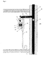
- Fig. 1 shows a condensing heater 1 according to the prior art.
- the calorific value heater 1 according to the prior art is room air independent and has a fan 10 for supplying combustion air to the boiler 12 on.
- a heat exchanger 13 is further arranged, which additionally extracts heat from the combustion gas and the heating is available.
- Accumulating condensate is collected in a condensate tray 24 and fed via a siphon 14 to a condensate line 16 leading to a neutralization box (not shown). In this neutralization box, the acidic concentrate is neutralized with limestone to gypsum and water.
- the exhaust gases of the calorific value heater 1 are led upwards via an internal exhaust gas guide 18 and fed via a rising tube 20 to a riser 32 of a chimney 30.
- Supply air for the combustion is sucked in the annular gap 31 of the chimney and preheated by the residual heat of the exhaust gas in the riser 32.
- the supply air then passes through a supply air duct 22 to the condensing boiler 1 where it is sucked by the fan 10 and is blown into the boiler 12.
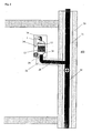
- FIG Fig. 2 shows symbolically a floor with a calorific value heater 1.
- the heating system 100 may include a plurality of condensing heaters 1, for example, on several floors, which are all connected to the illustrated common fireplace 30.
- the calorific value heater 1 comprises a fan 10 for the supply of combustion air to the boiler 12.
- water for heating or domestic water is heated in a heat exchanger 13.
- Resulting condensate is collected in a condensate tray 24.
- the condensate tray 24 is preferably formed symmetrically and has an outlet 26 which is arranged centrally in the condensate tray 24. Through this outlet 26, which opens down, both condensate from the condensate pan 24 and the resulting exhaust gases is discharged simultaneously.
- a falling arranged pipe 28 is connected, which connects the condensing boiler with a riser 32 of a chimney 30.
- the exhaust gas and the condensate arising in the condensing boiler 1 are led to the riser 32 via this falling pipe 28.
- Supply air to the condensing boiler 1 is sucked through the annular gap 31 and fed via a supply air duct 22 to the condensing boiler 1.
- the calorific value heater 1 according to the invention can therefore be carried out in principle both room air-dependent and room air independent.
- the supply air is preheated by the residual heat of the exhaust gas in the chimney 30, which operates as a countercurrent heat exchanger.
- a non-return valve 34 is provided which prevents that exhaust gases flow through the boiler 12 and through the fan 10 in the housing of the condensing boiler.
- the pressure conditions in the system 100 of condensing boiler 1 and the chimney 30 are shown.
- the fan 10 draws fresh air through the housing of the condensing boiler 1 from the supply air duct 22 and out of the annular gap 31 of the fireplace. Therefore prevails in the housing 1, a negative pressure to supply air.
- the exhaust gases are quasi pumped by the fan 10 down through the pipe 28 into the riser 32 of the chimney 30.
- the accumulated condensate flows purely by gravity over the falling pipeline arranged in the riser 32 from. Expensive and maintenance-prone condensate pumps can thus be avoided. Likewise, it is not necessary in the condensing boiler to dissipate the exhaust gas consuming upwards.
- the condensing boiler 1 can therefore be made smaller or, with identical dimensions, more powerful.
- the pipe 28 preferably has a slope of 1 ° - 10 °, more preferably of 2 ° - 5 ° and in a specific embodiment of 3 °. Due to this gradient, no condensate can accumulate. Thus, it is also possible, if in a floor no condensing boiler 1 is connected to close the falling arranged pipe 28 with a lid, which is ensured by the falling arrangement that here no condensate can accumulate. In addition, the supply air duct 22 should be closed, so that the preheated supply air does not escape undesirable or room air is sucked.
- the non-return valve 34 is preferably designed as a small non-return membrane made of silicone in the intake silencer of the fan 10.
- a second backflow preventer 34 can be arranged behind the first backflow lock 34 in order not to introduce any exhaust gas into the supply air in the event of a defect in the membrane.
- an exhaust gas outlet from the boiler into the installation room is excluded, even if the membrane is defective, since the boiler housing, together with the supply air supply, is made airtight.
- Fig. 2 can be seen schematically, the condensing boiler 1 through the bottom exhaust system is very accessible to the chimney sweeper.
- An inspection opening which is present in the pipeline 28 and the supply air duct 22, is at working height and no longer has to be reached with ladders or chairs. This increases service friendliness and control work can be carried out at an ergonomic height. Also, the installation of the calorific value heater 1 on the wall and the connection to the chimney 30 is facilitated.
- the calorific value heater 1 can be attached to any wall at any height. Due to the downward pointing combined exhaust and condensate outlet, the design-related smaller size and the lack of additional connection to the sewer system, the condensing boiler 1 can be much better integrated into furniture pieces than conventional condensing boilers.
- the condensing boiler 1 is particularly suitable for system 100, in which several condensing heaters (for example, for each floor or for each apartment one) are connected to a common fireplace 30. Then the accumulating condensate of all condensing heaters is introduced into the riser 32 and can be caught by a large siphon on Kaminsockel and fed to the neutralization. The fact that several calorific value heaters introduce their condensate in the riser 32, the risk that the Siphon falls dry. In addition, rain and snow can penetrate into the riser 32 and helps to avoid this as well.
- the condensing boiler 1 in itself does not need a separate siphon for condensate removal. Also no condensate pump is needed.
- Due to the falling arrangement of the pipe 28 may additionally water, which is obtained in certain situations at a pressure relief valve of the heating circuit, are derived.
- the water accumulating on the pressure relief valve is preferably introduced into the condensate tray and / or discharged via the falling pipe 28 into the riser pipe 32 of the chimney 30.
Landscapes
- Engineering & Computer Science (AREA)
- Physics & Mathematics (AREA)
- Thermal Sciences (AREA)
- Chemical & Material Sciences (AREA)
- Combustion & Propulsion (AREA)
- Mechanical Engineering (AREA)
- General Engineering & Computer Science (AREA)
- Air Supply (AREA)
Priority Applications (1)
| Application Number | Priority Date | Filing Date | Title |
|---|---|---|---|
| EP08017636A EP2175209B9 (fr) | 2008-10-08 | 2008-10-08 | Appareil de chauffage à valeur combustible |
Applications Claiming Priority (1)
| Application Number | Priority Date | Filing Date | Title |
|---|---|---|---|
| EP08017636A EP2175209B9 (fr) | 2008-10-08 | 2008-10-08 | Appareil de chauffage à valeur combustible |
Publications (3)
| Publication Number | Publication Date |
|---|---|
| EP2175209A1 true EP2175209A1 (fr) | 2010-04-14 |
| EP2175209B1 EP2175209B1 (fr) | 2012-09-12 |
| EP2175209B9 EP2175209B9 (fr) | 2013-01-09 |
Family
ID=40491083
Family Applications (1)
| Application Number | Title | Priority Date | Filing Date |
|---|---|---|---|
| EP08017636A Not-in-force EP2175209B9 (fr) | 2008-10-08 | 2008-10-08 | Appareil de chauffage à valeur combustible |
Country Status (1)
| Country | Link |
|---|---|
| EP (1) | EP2175209B9 (fr) |
Cited By (3)
| Publication number | Priority date | Publication date | Assignee | Title |
|---|---|---|---|---|
| GB2489425A (en) * | 2011-03-25 | 2012-10-03 | Adey Holdings 2008 Ltd | Preventing freezing in a boiler condensate drain pipe |
| WO2014106758A1 (fr) * | 2013-01-07 | 2014-07-10 | Ideal Boilers Limited | Chaudière à condensation |
| ITUA20162269A1 (it) * | 2016-04-04 | 2017-10-04 | Colombo Claudio | Impianto di riscaldamento a caldaia di condensazione |
Citations (6)
| Publication number | Priority date | Publication date | Assignee | Title |
|---|---|---|---|---|
| DE1812361A1 (de) * | 1968-12-03 | 1970-06-18 | Vaillant Joh Kg | Rueckstromsicherung |
| DE9105119U1 (de) * | 1991-04-25 | 1993-03-04 | H. Schlegel AG, Kaminbau, Kirchberg | Doppelzugschornstein |
| DE4237134A1 (en) | 1991-10-31 | 1993-05-06 | Joh. Vaillant Gmbh U. Co, 5630 Remscheid, De | Multi-floor-building exhaust pipe system - has condensate drains from heater burners connected to common down-pipe |
| EP0926439A2 (fr) | 1997-12-23 | 1999-06-30 | Renato Montini | Chaudière à gaz |
| EP1398579A1 (fr) | 2002-09-05 | 2004-03-17 | Thermital Spa | Chaudière à condensation à haut rapport de modulation |
| DE102005003868A1 (de) | 2004-01-26 | 2005-08-11 | Vaillant Gmbh | Vorrichtung zur Kondensatabführung in einer Brennwert-Heizungsanlage |
-
2008
- 2008-10-08 EP EP08017636A patent/EP2175209B9/fr not_active Not-in-force
Patent Citations (6)
| Publication number | Priority date | Publication date | Assignee | Title |
|---|---|---|---|---|
| DE1812361A1 (de) * | 1968-12-03 | 1970-06-18 | Vaillant Joh Kg | Rueckstromsicherung |
| DE9105119U1 (de) * | 1991-04-25 | 1993-03-04 | H. Schlegel AG, Kaminbau, Kirchberg | Doppelzugschornstein |
| DE4237134A1 (en) | 1991-10-31 | 1993-05-06 | Joh. Vaillant Gmbh U. Co, 5630 Remscheid, De | Multi-floor-building exhaust pipe system - has condensate drains from heater burners connected to common down-pipe |
| EP0926439A2 (fr) | 1997-12-23 | 1999-06-30 | Renato Montini | Chaudière à gaz |
| EP1398579A1 (fr) | 2002-09-05 | 2004-03-17 | Thermital Spa | Chaudière à condensation à haut rapport de modulation |
| DE102005003868A1 (de) | 2004-01-26 | 2005-08-11 | Vaillant Gmbh | Vorrichtung zur Kondensatabführung in einer Brennwert-Heizungsanlage |
Cited By (3)
| Publication number | Priority date | Publication date | Assignee | Title |
|---|---|---|---|---|
| GB2489425A (en) * | 2011-03-25 | 2012-10-03 | Adey Holdings 2008 Ltd | Preventing freezing in a boiler condensate drain pipe |
| WO2014106758A1 (fr) * | 2013-01-07 | 2014-07-10 | Ideal Boilers Limited | Chaudière à condensation |
| ITUA20162269A1 (it) * | 2016-04-04 | 2017-10-04 | Colombo Claudio | Impianto di riscaldamento a caldaia di condensazione |
Also Published As
| Publication number | Publication date |
|---|---|
| EP2175209B9 (fr) | 2013-01-09 |
| EP2175209B1 (fr) | 2012-09-12 |
Similar Documents
| Publication | Publication Date | Title |
|---|---|---|
| EP2385302B1 (fr) | Système de cheminée | |
| EP2175209B9 (fr) | Appareil de chauffage à valeur combustible | |
| EP2322870B1 (fr) | Chaudière à condensation | |
| EP0264907A2 (fr) | Chaudière de chauffage à combustibles liquides | |
| EP1131583A1 (fr) | Dispositif et procede pour chauffer et/ou aerer une piece | |
| AT404633B (de) | Kondensatableitung für mehrere jeweils einen brenner aufweisende brennwertheizgeräte | |
| EP0533629A1 (fr) | Méthode et dispositif d'approvisionnement en air frais chauffé | |
| DE19852640A1 (de) | Kamin für die Be- und Entlüftung eines Hauses mit einem feuerbeständigen, aus Mantelsteinen aufgebauten Schacht | |
| DE102005003868B4 (de) | Vorrichtung zur Kondensatabführung in einer Brennwert-Heizungsanlage | |
| DE102018201780A1 (de) | Entlüftungsvorrichtung zum Abscheiden und Ausleiten von Gas aus einem flüssigen Medium | |
| EP2172717B1 (fr) | Appareil de chauffage | |
| EP1939530B1 (fr) | Dispositif supplémentaire pour fours de cheminée | |
| EP2295890A2 (fr) | Siphon pour un appareil de chauffage | |
| EP3620717A1 (fr) | Module de four pour bâtiments | |
| DE102023102607A1 (de) | Verfahren zur Umrüstung einer Immobilie mit einer Luft-Wasser-Wärmepumpe sowie Immobilie | |
| EP3056812A1 (fr) | Installation de combustion ou electrochimique comprenant un ventilateur et un siphon de condensat | |
| DE10247834A1 (de) | Kaminrohr mit Kondensateinleitung | |
| DE19546459C2 (de) | Verfahren zum Austausch einer zentralen Wärmeerzeugungsvorrichtung durch eine neue zentrale Wärmeerzeugungseinrichtung in einem Gebäude sowie Verfahren zum Einbau einer zentralen Wärmeerzeugungseinrichtung in ein Gebäude | |
| DE102018218759A1 (de) | Überwachungsvorrichtung für ein Brennwertheizgerät | |
| DE3539311A1 (de) | Schornstein-, lueftungs- und feuerungssystem | |
| DE102014103447A1 (de) | Heizungsanlage | |
| DE19170C (de) | Centrai-Dampfheizung mit selbsttätigem Druckregulator | |
| DE33306C (de) | Heizkörper mit einer Vorrichtung zum Absaugen von Luft | |
| DE202009010607U1 (de) | Heizgerät | |
| DE102024110960A1 (de) | Hybrid-Heizungssystem |
Legal Events
| Date | Code | Title | Description |
|---|---|---|---|
| PUAI | Public reference made under article 153(3) epc to a published international application that has entered the european phase |
Free format text: ORIGINAL CODE: 0009012 |
|
| 17P | Request for examination filed |
Effective date: 20090831 |
|
| AK | Designated contracting states |
Kind code of ref document: A1 Designated state(s): AT BE BG CH CY CZ DE DK EE ES FI FR GB GR HR HU IE IS IT LI LT LU LV MC MT NL NO PL PT RO SE SI SK TR |
|
| AX | Request for extension of the european patent |
Extension state: AL BA MK RS |
|
| AKX | Designation fees paid |
Designated state(s): AT BE BG CH CY CZ DE DK EE ES FI FR GB GR HR HU IE IS IT LI LT LU LV MC MT NL NO PL PT RO SE SI SK TR |
|
| GRAP | Despatch of communication of intention to grant a patent |
Free format text: ORIGINAL CODE: EPIDOSNIGR1 |
|
| GRAS | Grant fee paid |
Free format text: ORIGINAL CODE: EPIDOSNIGR3 |
|
| GRAA | (expected) grant |
Free format text: ORIGINAL CODE: 0009210 |
|
| AK | Designated contracting states |
Kind code of ref document: B1 Designated state(s): AT BE BG CH CY CZ DE DK EE ES FI FR GB GR HR HU IE IS IT LI LT LU LV MC MT NL NO PL PT RO SE SI SK TR |
|
| REG | Reference to a national code |
Ref country code: GB Ref legal event code: FG4D Free format text: NOT ENGLISH |
|
| REG | Reference to a national code |
Ref country code: CH Ref legal event code: EP |
|
| REG | Reference to a national code |
Ref country code: AT Ref legal event code: REF Ref document number: 575281 Country of ref document: AT Kind code of ref document: T Effective date: 20120915 |
|
| REG | Reference to a national code |
Ref country code: IE Ref legal event code: FG4D Free format text: LANGUAGE OF EP DOCUMENT: GERMAN |
|
| REG | Reference to a national code |
Ref country code: DE Ref legal event code: R096 Ref document number: 502008008140 Country of ref document: DE Effective date: 20121108 |
|
| REG | Reference to a national code |
Ref country code: NL Ref legal event code: T3 |
|
| PG25 | Lapsed in a contracting state [announced via postgrant information from national office to epo] |
Ref country code: HR Free format text: LAPSE BECAUSE OF FAILURE TO SUBMIT A TRANSLATION OF THE DESCRIPTION OR TO PAY THE FEE WITHIN THE PRESCRIBED TIME-LIMIT Effective date: 20120912 Ref country code: NO Free format text: LAPSE BECAUSE OF FAILURE TO SUBMIT A TRANSLATION OF THE DESCRIPTION OR TO PAY THE FEE WITHIN THE PRESCRIBED TIME-LIMIT Effective date: 20121212 Ref country code: LT Free format text: LAPSE BECAUSE OF FAILURE TO SUBMIT A TRANSLATION OF THE DESCRIPTION OR TO PAY THE FEE WITHIN THE PRESCRIBED TIME-LIMIT Effective date: 20120912 Ref country code: CY Free format text: LAPSE BECAUSE OF FAILURE TO SUBMIT A TRANSLATION OF THE DESCRIPTION OR TO PAY THE FEE WITHIN THE PRESCRIBED TIME-LIMIT Effective date: 20120912 Ref country code: FI Free format text: LAPSE BECAUSE OF FAILURE TO SUBMIT A TRANSLATION OF THE DESCRIPTION OR TO PAY THE FEE WITHIN THE PRESCRIBED TIME-LIMIT Effective date: 20120912 |
|
| REG | Reference to a national code |
Ref country code: LT Ref legal event code: MG4D Effective date: 20120912 |
|
| PG25 | Lapsed in a contracting state [announced via postgrant information from national office to epo] |
Ref country code: GR Free format text: LAPSE BECAUSE OF FAILURE TO SUBMIT A TRANSLATION OF THE DESCRIPTION OR TO PAY THE FEE WITHIN THE PRESCRIBED TIME-LIMIT Effective date: 20121213 Ref country code: LV Free format text: LAPSE BECAUSE OF FAILURE TO SUBMIT A TRANSLATION OF THE DESCRIPTION OR TO PAY THE FEE WITHIN THE PRESCRIBED TIME-LIMIT Effective date: 20120912 Ref country code: SI Free format text: LAPSE BECAUSE OF FAILURE TO SUBMIT A TRANSLATION OF THE DESCRIPTION OR TO PAY THE FEE WITHIN THE PRESCRIBED TIME-LIMIT Effective date: 20120912 Ref country code: SE Free format text: LAPSE BECAUSE OF FAILURE TO SUBMIT A TRANSLATION OF THE DESCRIPTION OR TO PAY THE FEE WITHIN THE PRESCRIBED TIME-LIMIT Effective date: 20120912 |
|
| BERE | Be: lapsed |
Owner name: WUNSCH, HORST Effective date: 20121031 |
|
| PG25 | Lapsed in a contracting state [announced via postgrant information from national office to epo] |
Ref country code: CZ Free format text: LAPSE BECAUSE OF FAILURE TO SUBMIT A TRANSLATION OF THE DESCRIPTION OR TO PAY THE FEE WITHIN THE PRESCRIBED TIME-LIMIT Effective date: 20120912 Ref country code: RO Free format text: LAPSE BECAUSE OF FAILURE TO SUBMIT A TRANSLATION OF THE DESCRIPTION OR TO PAY THE FEE WITHIN THE PRESCRIBED TIME-LIMIT Effective date: 20120912 Ref country code: IS Free format text: LAPSE BECAUSE OF FAILURE TO SUBMIT A TRANSLATION OF THE DESCRIPTION OR TO PAY THE FEE WITHIN THE PRESCRIBED TIME-LIMIT Effective date: 20130112 Ref country code: EE Free format text: LAPSE BECAUSE OF FAILURE TO SUBMIT A TRANSLATION OF THE DESCRIPTION OR TO PAY THE FEE WITHIN THE PRESCRIBED TIME-LIMIT Effective date: 20120912 Ref country code: ES Free format text: LAPSE BECAUSE OF FAILURE TO SUBMIT A TRANSLATION OF THE DESCRIPTION OR TO PAY THE FEE WITHIN THE PRESCRIBED TIME-LIMIT Effective date: 20121223 |
|
| PG25 | Lapsed in a contracting state [announced via postgrant information from national office to epo] |
Ref country code: PT Free format text: LAPSE BECAUSE OF FAILURE TO SUBMIT A TRANSLATION OF THE DESCRIPTION OR TO PAY THE FEE WITHIN THE PRESCRIBED TIME-LIMIT Effective date: 20130114 Ref country code: MC Free format text: LAPSE BECAUSE OF NON-PAYMENT OF DUE FEES Effective date: 20121031 Ref country code: PL Free format text: LAPSE BECAUSE OF FAILURE TO SUBMIT A TRANSLATION OF THE DESCRIPTION OR TO PAY THE FEE WITHIN THE PRESCRIBED TIME-LIMIT Effective date: 20120912 Ref country code: SK Free format text: LAPSE BECAUSE OF FAILURE TO SUBMIT A TRANSLATION OF THE DESCRIPTION OR TO PAY THE FEE WITHIN THE PRESCRIBED TIME-LIMIT Effective date: 20120912 |
|
| REG | Reference to a national code |
Ref country code: NL Ref legal event code: T3 |
|
| REG | Reference to a national code |
Ref country code: IE Ref legal event code: MM4A |
|
| PLBE | No opposition filed within time limit |
Free format text: ORIGINAL CODE: 0009261 |
|
| STAA | Information on the status of an ep patent application or granted ep patent |
Free format text: STATUS: NO OPPOSITION FILED WITHIN TIME LIMIT |
|
| PG25 | Lapsed in a contracting state [announced via postgrant information from national office to epo] |
Ref country code: BG Free format text: LAPSE BECAUSE OF FAILURE TO SUBMIT A TRANSLATION OF THE DESCRIPTION OR TO PAY THE FEE WITHIN THE PRESCRIBED TIME-LIMIT Effective date: 20121212 Ref country code: DK Free format text: LAPSE BECAUSE OF FAILURE TO SUBMIT A TRANSLATION OF THE DESCRIPTION OR TO PAY THE FEE WITHIN THE PRESCRIBED TIME-LIMIT Effective date: 20120912 Ref country code: IE Free format text: LAPSE BECAUSE OF NON-PAYMENT OF DUE FEES Effective date: 20121008 Ref country code: BE Free format text: LAPSE BECAUSE OF NON-PAYMENT OF DUE FEES Effective date: 20121031 |
|
| 26N | No opposition filed |
Effective date: 20130613 |
|
| GBPC | Gb: european patent ceased through non-payment of renewal fee |
Effective date: 20121212 |
|
| PG25 | Lapsed in a contracting state [announced via postgrant information from national office to epo] |
Ref country code: IT Free format text: LAPSE BECAUSE OF FAILURE TO SUBMIT A TRANSLATION OF THE DESCRIPTION OR TO PAY THE FEE WITHIN THE PRESCRIBED TIME-LIMIT Effective date: 20120912 |
|
| REG | Reference to a national code |
Ref country code: DE Ref legal event code: R097 Ref document number: 502008008140 Country of ref document: DE Effective date: 20130613 |
|
| PG25 | Lapsed in a contracting state [announced via postgrant information from national office to epo] |
Ref country code: GB Free format text: LAPSE BECAUSE OF NON-PAYMENT OF DUE FEES Effective date: 20121212 Ref country code: MT Free format text: LAPSE BECAUSE OF FAILURE TO SUBMIT A TRANSLATION OF THE DESCRIPTION OR TO PAY THE FEE WITHIN THE PRESCRIBED TIME-LIMIT Effective date: 20120912 |
|
| PG25 | Lapsed in a contracting state [announced via postgrant information from national office to epo] |
Ref country code: TR Free format text: LAPSE BECAUSE OF FAILURE TO SUBMIT A TRANSLATION OF THE DESCRIPTION OR TO PAY THE FEE WITHIN THE PRESCRIBED TIME-LIMIT Effective date: 20120912 |
|
| PG25 | Lapsed in a contracting state [announced via postgrant information from national office to epo] |
Ref country code: LU Free format text: LAPSE BECAUSE OF NON-PAYMENT OF DUE FEES Effective date: 20121008 |
|
| PG25 | Lapsed in a contracting state [announced via postgrant information from national office to epo] |
Ref country code: HU Free format text: LAPSE BECAUSE OF FAILURE TO SUBMIT A TRANSLATION OF THE DESCRIPTION OR TO PAY THE FEE WITHIN THE PRESCRIBED TIME-LIMIT Effective date: 20081008 |
|
| REG | Reference to a national code |
Ref country code: AT Ref legal event code: MM01 Ref document number: 575281 Country of ref document: AT Kind code of ref document: T Effective date: 20131008 |
|
| PGFP | Annual fee paid to national office [announced via postgrant information from national office to epo] |
Ref country code: CH Payment date: 20141024 Year of fee payment: 7 Ref country code: FR Payment date: 20141021 Year of fee payment: 7 |
|
| PG25 | Lapsed in a contracting state [announced via postgrant information from national office to epo] |
Ref country code: AT Free format text: LAPSE BECAUSE OF NON-PAYMENT OF DUE FEES Effective date: 20131008 |
|
| PGFP | Annual fee paid to national office [announced via postgrant information from national office to epo] |
Ref country code: NL Payment date: 20141023 Year of fee payment: 7 |
|
| REG | Reference to a national code |
Ref country code: CH Ref legal event code: PL |
|
| REG | Reference to a national code |
Ref country code: NL Ref legal event code: MM Effective date: 20151101 |
|
| PG25 | Lapsed in a contracting state [announced via postgrant information from national office to epo] |
Ref country code: LI Free format text: LAPSE BECAUSE OF NON-PAYMENT OF DUE FEES Effective date: 20151031 Ref country code: CH Free format text: LAPSE BECAUSE OF NON-PAYMENT OF DUE FEES Effective date: 20151031 |
|
| REG | Reference to a national code |
Ref country code: FR Ref legal event code: ST Effective date: 20160630 |
|
| PG25 | Lapsed in a contracting state [announced via postgrant information from national office to epo] |
Ref country code: NL Free format text: LAPSE BECAUSE OF NON-PAYMENT OF DUE FEES Effective date: 20151101 Ref country code: FR Free format text: LAPSE BECAUSE OF NON-PAYMENT OF DUE FEES Effective date: 20151102 |
|
| REG | Reference to a national code |
Ref country code: DE Ref legal event code: R082 Ref document number: 502008008140 Country of ref document: DE Representative=s name: BARDEHLE PAGENBERG PARTNERSCHAFT MBB PATENTANW, DE Ref country code: DE Ref legal event code: R081 Ref document number: 502008008140 Country of ref document: DE Owner name: TECHNAFLON KAMINSYSTEME AG, CH Free format text: FORMER OWNER: WUNSCH, HORST, LANDSCHLACHT, CH |
|
| PGFP | Annual fee paid to national office [announced via postgrant information from national office to epo] |
Ref country code: DE Payment date: 20231025 Year of fee payment: 16 |
|
| REG | Reference to a national code |
Ref country code: DE Ref legal event code: R119 Ref document number: 502008008140 Country of ref document: DE |
|
| PG25 | Lapsed in a contracting state [announced via postgrant information from national office to epo] |
Ref country code: DE Free format text: LAPSE BECAUSE OF NON-PAYMENT OF DUE FEES Effective date: 20250501 |