EP2177391A1 - Fahrzeugsitzschiebevorrichtung - Google Patents
Fahrzeugsitzschiebevorrichtung Download PDFInfo
- Publication number
- EP2177391A1 EP2177391A1 EP09171224A EP09171224A EP2177391A1 EP 2177391 A1 EP2177391 A1 EP 2177391A1 EP 09171224 A EP09171224 A EP 09171224A EP 09171224 A EP09171224 A EP 09171224A EP 2177391 A1 EP2177391 A1 EP 2177391A1
- Authority
- EP
- European Patent Office
- Prior art keywords
- rail
- terms
- portions
- wall portions
- side wall
- Prior art date
- Legal status (The legal status is an assumption and is not a legal conclusion. Google has not performed a legal analysis and makes no representation as to the accuracy of the status listed.)
- Granted
Links
- 230000000994 depressogenic effect Effects 0.000 claims description 3
- 210000000078 claw Anatomy 0.000 description 6
- 230000002093 peripheral effect Effects 0.000 description 3
- 230000000452 restraining effect Effects 0.000 description 3
- 238000005096 rolling process Methods 0.000 description 3
- 230000015572 biosynthetic process Effects 0.000 description 2
- 210000004709 eyebrow Anatomy 0.000 description 2
Images
Classifications
-
- B—PERFORMING OPERATIONS; TRANSPORTING
- B60—VEHICLES IN GENERAL
- B60N—SEATS SPECIALLY ADAPTED FOR VEHICLES; VEHICLE PASSENGER ACCOMMODATION NOT OTHERWISE PROVIDED FOR
- B60N2/00—Seats specially adapted for vehicles; Arrangement or mounting of seats in vehicles
- B60N2/02—Seats specially adapted for vehicles; Arrangement or mounting of seats in vehicles the seat or part thereof being movable, e.g. adjustable
- B60N2/04—Seats specially adapted for vehicles; Arrangement or mounting of seats in vehicles the seat or part thereof being movable, e.g. adjustable the whole seat being movable
- B60N2/06—Seats specially adapted for vehicles; Arrangement or mounting of seats in vehicles the seat or part thereof being movable, e.g. adjustable the whole seat being movable slidable
- B60N2/07—Slide construction
- B60N2/0722—Constructive details
- B60N2/0725—Closing members for covering the slide
-
- B—PERFORMING OPERATIONS; TRANSPORTING
- B60—VEHICLES IN GENERAL
- B60N—SEATS SPECIALLY ADAPTED FOR VEHICLES; VEHICLE PASSENGER ACCOMMODATION NOT OTHERWISE PROVIDED FOR
- B60N2/00—Seats specially adapted for vehicles; Arrangement or mounting of seats in vehicles
- B60N2/02—Seats specially adapted for vehicles; Arrangement or mounting of seats in vehicles the seat or part thereof being movable, e.g. adjustable
- B60N2/04—Seats specially adapted for vehicles; Arrangement or mounting of seats in vehicles the seat or part thereof being movable, e.g. adjustable the whole seat being movable
- B60N2/06—Seats specially adapted for vehicles; Arrangement or mounting of seats in vehicles the seat or part thereof being movable, e.g. adjustable the whole seat being movable slidable
- B60N2/07—Slide construction
- B60N2/0722—Constructive details
- B60N2/0727—Stop members for limiting sliding movement
Definitions
- the present invention relates to a vehicle seat sliding apparatus.
- a vehicle seat sliding apparatus as disclosed in JP-A-2006-298104 (Fig. 7 to Fig. 8) is known.
- This vehicle seat sliding apparatus includes a lower rail adapted to be fixed to a vehicle-floor, and an upper rail adapted to be fixed to a seat cushion and supported so as to be movable relative to the lower rail.
- the lower rail is provided at a center portion thereof in terms of the longitudinal direction with a cut-and-raised strip which is formed by cutting and raising obliquely from a bottom wall portion.
- the upper rail is provided at front and rear end portions thereof with cut-and-raised strips formed by cutting and raising obliquely from a vertical wall portion (32).
- cut-and-raised strips are arranged so that parts of the respective opposed surfaces opposing in terms of the direction of movement of the upper rail are able to abut thereto, and restricts the movable range (slide stroke) of the upper rail with respect to the lower rail by being engaged in association with the movement of the upper rail.
- the cut-and-raised strips disposed at the front and rear end portions of the upper rail are exposed and may interfere with peripheral components depending on the relative position of the upper rail with respect to the lower rail such that the front end portion or the rear end portion of the upper rail projects from the lower rail.
- a first aspect of the invention provides a vehicle seat sliding apparatus including: a first rail adapted to be fixed to either one of a vehicle-floor or a seat cushlon; a second rail adapted to be connected to the first rail so as to be movable relatively therewith so as to be fixed to the other of the vehicle-floor and the seat cushion and provided with a pair of side wall portions arranged in parallel on both sides in terms of the widthwise direction and a connecting wall portion being opposed to the first rail in terms of the vehicle height direction and connecting proximal ends of the both side wall portions apart from the first rail; a projecting portion provided at an end portion of the second rail in terms of the longitudinal direction at an end portion of an opening formed by distal end portions of the side wall portions so as to project between the both side wall portions in terms of the widthwise direction of the second rail; and a cover adapted to be mounted on the second rail and to close a terminal end of the second rail, wherein the cover include an extending portion extending to a
- a second aspect of the invention is directed to the vehicle seat sliding apparatus of the first aspect, wherein the first rail including a stopper portion, and the projecting portion is a cut-and-raised portion adapted to restrict the allowable range of relative movement between the first and second rails by engaging the stopper portion in association with the relative movement of the first and second rails.
- a third aspect of the invention is directed to the vehicle seat sliding apparatus of the second aspect, wherein the second rail includes a pair of the cut-and-raised portions on both sides In terms of the widthwise direction, the first rail is adapted to be fixable to the vehicle-floor by a tightening member arranged at a center portion opposing a portion between the both cut-and-raised portions in terms of the widthwise direction, and the extending portion includes a recess depressed at a center portion in terms of the widthwise direction on the side opposite from the direction of the opening of the second rail.
- the both sides of the recess in terms of the widthwise direction projects sufflcientiy toward the opening of the second rail while restraining interference between the head portion of the tightening member which can be opposed to the opening, so that the exposure of the distal ends of the both cut-and-raised portions can be restrained reliably.
- a fourth aspect of the invention is directed to the vehicle seat sliding apparatus of any of the first to third aspects, wherein the cover includes: a cover portion adapted to cover a distal end surface of the terminal end of the second rail and including the extending portion Interposed between the both side wall portions and projected in the longitudinal direction of the second rail, and a pair of engaging portions projecting from the extending portion outward on both sides in terms of the widthwise direction and engage the both side wall portions.
- the distal end surface of the terminal end of the second rail is covered with the cover portion, the appearance is improved. Also, since the pair of engaging portions engage the both side wall portions, the cover can be held further stably.
- the vehicle seat sliding apparatus in which the exposure of the projecting portions provided on the rail is restrained, and the interference with the peripheral components can be restrained further reliably.
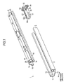
- Fig. 1 and Fig. 2 are a perspective view and a cross-sectional view showing a vehicle seat sliding apparatus 1 according to the embodiment which is mounted on a vehicle such as an automotive vehicle, for example.
- a lower rail 3 as a first rail is fixed to a vehicle-floor 90 in a state of extending in the fore-and-aft direction of the vehicle
- an upper rail 4 as a second rail is mounted to the lower rail 3 so as to be movable relatively to the lower rail 3.
- a seat cushion 80 is fixed to the upper rail 4.
- the lower rail 3 and the upper rail 4 are disposed in pairs respectively in the widthwise direction of the vehicle seat cushion 80. Then, a seat cushion which forms a seating portion for an occupant is fixed to and supported by the both upper rails 4.
- the relative movement of the lower rail 3 and the upper rail 4 is normally restricted by a locking member (not shown), and the restriction is released by applying an operating force to the locking member.
- the lower rail 3 includes a pair of side wall portions 11 extending upright from both sides thereof in terms of the widthwise direction and a bottom wall portion 12 which connects proximal ends (lower ends) of the side wall portions 11. Then, folded-back wall portions 13 which are formed to protrude inward in terms of the widthwise direction and then folded back toward the proximal end sides of the side wall portions 11 are formed continuously from distal ends (upper ends) of the respective side wall portions 11.
- the upper rail 4 includes a pair of side wall portions 14 extending in the vertical direction between the both folded-back wall portions 13 of the lower rail 3 and a lid wall portion 15 as a connecting wall portion connecting proximal ends (upper ends) apart from the lower rail 3 of the side wall portions 14.
- folded-back wall portions 16 which are formed to protrude outward in terms of the widthwise direction and then folded so as to be surrounded by the side wall portions 11 and the folded-back wall portions 13 are formed continuously from distal ends (lower ends) of the respective side wall portions 14.
- the lower rail 3 and the upper rail 4 each include a U-shaped cross section of the rail with opening sides butted against to each other, and are held so as not to come apart from each other in the vertical direction mainly by the engagement of the folded-back wall portions 13 and 16.
- the cross section of the rail formed by the lower rail 3 and the upper rail 4 assumes so-called a box shape in a rectangular shape.
- the lower rail 3 defines an internal space S in cooperation with the upper rail 4 (see Fig. 2 ).
- the lower rail 3 is fixed to a vehicle-floor by a bolt 60 (see Fig. 3C ) as a tightening member arranged at a center portion of the bottom wall portion 12 in terms of the widthwise direction, and a pan-shaped head portion 60a of the bolt 60 projects into the internal space S.
- Rolling elements (not shown) are mounted between the respective folded-back wall portions 16 and the side wall portions 11 opposing thereto, and the upper rail 4 is supported so as to be slidable in the longitudinal direction (the fore-and-aft direction of the vehicle) with respect to the lower rail 3 in a state of rolling the rolling elements with respect to the lower rail 3.
- the lower rail 3 is formed with a pair of cut-and-raised strips 41 as stopper portions arranged on the bottom wall portion 12 symmetrically in terms of the widthwise direction at a center portion in terms of the longitudinal direction of the lower rall 3.
- the pair of cut-and-raised strips 41 are cut and raised at a predetermined angle so as to assume the shape of slanting eyebrows reducing the distance toward the upper ends thereof, and project Into the internal space S.
- the respective cut-and-raised strips 41 extend in the longitudinal direction of the lower rail 3, that is, in the direction of the relative movements of the lower rail 3 and the upper rail 4.
- incised portions 42 are formed in association with the formation of the cut-and-raised strips 41 (cut and raised portions) around the respective cut-and-raised strips 41.
- a pair of projecting portions and cut-and-raised strips 46 as cut-and-raised portions arranged symmetrically in the widthwise direction are formed at a connecting portion between the side wall portions 14 and the folded-back wall portions 16.
- the pair of cut-and-raised strips 46 are cut and raised at a predetermined angle so as to assume the shape of flat slanting eyebrows reducing the distance toward the upper ends thereof, and project into the internal space S.
- the respective cut-and-raised strips 46 extend in the direction of the relative movement of the lower rail 3 and the upper rail 4.
- incised portions 47 are formed in association with the formation of the cut-and-raised strips 46 (cut and raised portions) around the respective cut-and-raised strips 46.
- the bolt 60 head portion 60a is arranged between the cut-and-raised strips 46 so as to oppose to each other in terms of the rail width direction.
- the both cut-and-raised strips 41 and 46 are arranged so that the respective opposed surfaces are able to come into abutment with each other in the direction of the relative movement of the lower rail 3 and the upper rail 4. Therefore, the both cut-and-raised strips 41 and 46, being engaged with each other in association with the relative movement of the lower rail 3 and the upper rail 4, restrict the allowable range of relative movement of the lower rail 3 and the upper rail 4.
- the respective side wall portions 14 are formed with lock holes 20 opening in the rail width direction at both end portions thereof in terms of the longitudinal direction Then, a resin-made cover 51 for closing the terminal end is mounted to the end portion of the upper rail 4 in terms of the longitudinal direction.
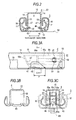
- Figs. 3A and 3B are a side view and a front view of the upper rail 4 on which the cover 51 is mounted
- Fig. 3C is a cross-sectional view taken along the line A-A in Fig. 3A . As shown in Fig. 1 and Figs.
- the cover 51 having a symmetrical structure in terms of the rail width direction, has a plate-shaped cover portion 52 molded into a hat shape corresponding to a plane of projection thereof including an internal space when viewing the upper rail 4 in the longitudinal direction, and an L-shaped pair of fitting wall portions 53 each having an outer wall surface which can be fitted to a U-shape formed by an inner wall surface of the pair of side wall portion 14 and the lid wall portion 15 and projecting from the cover portion 52 along the longitudinal direction of the upper rail 4, and also includes a trapezoidal-shaped pair of fitting projections 54 each having an outer wall surface which can be fitted to a curved shape formed by an inner wall surface of the folded-back wall portion 16 and projecting from the cover portion 52 along the longitudinal direction of the upper rall 4.
- the cover 51 includes a boat-shaped extending portion 55 projecting from the cover portion 52 along the longitudinal direction of the upper rail 4 inside the both fitting wall portions 53 in the rail width direction.
- the extending portion 55 includes a pair of side walls 55a arranged in parallel to the side wall portion 14 in the rail width direction, includes an arcuate-shaped distal end wall 55b connecting upper distal portions of the side walls 55a, and also includes a step-shaped connecting wall 55c extending in the longitudinal direction of the extending portion 55 at a midsection of a space formed between the distal end wall 55b and the cover portion 52 in terms of the height direction and connecting the both side walls 55a in the rail width direction.
- a pair of locking claws 56 extending in the longitudinal direction of the upper rail 4 from a midsection of the fitting wall portion 53 in terms of the height direction so as to be capable of fitting into the lock holes 20 are formed so as to project outward in terms of the rail width direction respectively.
- a pair of ribs 57 extending in the longitudinal direction of the upper rail 4 on the distal end side, which corresponds to the lower side of the distal end wall 55b so as to be capable of press-fitting with an inner wall surface of the side wall portion 14 so as to project outward in terms of the rail with direction respectively.
- the extending portion 55 (both side walls 55a) of the cover 51 mounted on the upper rail 4 extends in the longitudinal direction of the upper rail 4 until a point P where the cut-and-raised strips 46 are formed including the entire cut-and-raised strips 46 in terms of the longitudinal direction of the upper rail 4, and projects toward the opening (downward) until distal ends of the cut-and-raised strips 46 in terms of the opening direction of the upper rail 4 as shown in Fig. 3C . Therefore, exposure of the distal ends (edges) of the cut-and-raised strips 46 is restrained by the extending portion 55.
- the extending portion 55 forms a step-shaped recess C depressed on the side opposite from the direction of opening of the upper rail 4 (the lid wall portion 15 side, that is, the side apart from the bottom wall portion 12 of the lower rail 3) at a center portion in terms of the widthwise direction. Therefore, for example, even though the head portion 60a of the bolt 60 projects upward by a minute distance ⁇ from a lower end of the cover 51 (both side walls 55a), interference with the head portion 60a is restrained by the recess C.
- the both fitting wall portions 53 of the cover 51 are fitted to a U-shape formed by inner wall surfaces of the pair of side wall portions 14 and the lid wall portion 15 and the both fitting projections 54 are fitted into a curved shape formed by the inner wall surfaces of the folded-back wall portions 16. Accordingly, the cover 51 is connected to the upper rail 4. At this time, the distal end surface at an terminal end of the upper rail 4 is covered by the cover portion 52 on the outside of the both fitting wall portions 53 and the fitting projection 54. Also, the distal ends (edges) of the both cut-and-raised strips 46 are covered with the extending portion 55 (both side walls 55a).
- the cut-and-raised strip 46 of the upper rail 4 and the cut-and-raised strip 41 of the lower rail 3 which can engage the cut-and-raised strip 46 may be arranged only on one side in terms of the widthwise direction.
- a separate stopper (a plate-shaped stopper, a bolt head, etc.) which can engage the cut-and-raised strip 46 may be employed instead of the cut-and-ralsed strip 41 formed on the lower rail 3.
- the recess arranged at the center portion of the extending portion 55 in terms of the widthwise direction may be a U-shaped groove.
- a rivet may be employed as the tightening member.
- the cut-and-raised portions may be disposed at both end portions of the lower rail 3 in terms of the longitudinal direction
- the stopper portion may be provided at the center portion of the upper rail 4 in terms of the longitudinal direction.
- the cover may be mounted at both end portions of the rail in terms of the longitudinal direction or may be mounted one of the end portions thereof.
- the "projecting portions” are the cut-and-raised strips 46 (cut-and-raised portions) formed by cutting and raising parts of the upper rail 4 at the end edges of the opening formed at the distal end portions of the side wall portions 14 of the upper rail 4 (second rail).
- the "projecting portions” do not necessarily have to be the cut-and-raised strips 46(cut-and-raised portion), and may be restricting members attached separately to the upper rail 4.
- the "projecting, portions” do not necessarily have to have a function to restrict the allowable range of relative movement of the both rails 3 and 4 by engaging the cut-and-raised strips 41 (stopper portions) formed on the lower rail 3 (first rail), and may be separate functional members projecting from the end edges of the opening formed by the distal end portions of the side wall portions 14 of the upper rail 4 in the widthwise direction.
- a mounting bracket for attaching a lock member for fixing the relative position of the both rails 3 and 4 by restraining the sliding movement of the upper rail 4 with respect to the lower rail 3 to the upper rail 4, or a terminal end portion of a lock spring for urging the lock member are exemplified.
- the cross-sectional shape of the lower rail 3 is shown simply as an example.
- the folded-back wall portions 13 may be protruded outward in terms of the rail width direction.
- the cross-sectional shape of the upper rail 4 is shown simply as an example.
- the folded-back wall portions 16 may be protruded inward in terms of the rail width direction.
- the cross section of the rail of the upper rail 4 is not limited to the U-shape, but may be an inverted T-shape, for example.
- the positional relation between the lower rail 3 and the upper rail 4 may be upside down.
- a configuration in which the upper rail 4 is fixed to the vehicle-floor and the lower rail 3 is fixed to the seat cushion is also applicable.
- the lower rail 3 and the upper rail 4 may be adapted to be disposed one each or three or more each for the seat cushion.
- the direction of movement of the seat in association with the movement of upper rail 4 with respect to the lower rail 3 may be, for example, the fore-and-aft direction or the widthwise direction of the vehicle.
- a vehicle seat sliding apparatus including:
- a cover member is provided at an end of the upper rail.
- the cover extends into the upper rail along its lengthwise direction to reach a portion at which the raised tab of the upper rail.
- the cover is provided with an extension extending to the raised tab of the upper rail.
Landscapes
- Engineering & Computer Science (AREA)
- Aviation & Aerospace Engineering (AREA)
- Transportation (AREA)
- Mechanical Engineering (AREA)
- Seats For Vehicles (AREA)
- Forklifts And Lifting Vehicles (AREA)
Priority Applications (1)
| Application Number | Priority Date | Filing Date | Title |
|---|---|---|---|
| PL09171224T PL2177391T3 (pl) | 2008-10-15 | 2009-09-24 | Urządzenie do przesuwania fotela pojazdu |
Applications Claiming Priority (1)
| Application Number | Priority Date | Filing Date | Title |
|---|---|---|---|
| JP2008266642A JP5287129B2 (ja) | 2008-10-15 | 2008-10-15 | 車両用シートスライド装置 |
Publications (2)
| Publication Number | Publication Date |
|---|---|
| EP2177391A1 true EP2177391A1 (de) | 2010-04-21 |
| EP2177391B1 EP2177391B1 (de) | 2011-01-26 |
Family
ID=41404480
Family Applications (1)
| Application Number | Title | Priority Date | Filing Date |
|---|---|---|---|
| EP09171224A Not-in-force EP2177391B1 (de) | 2008-10-15 | 2009-09-24 | Fahrzeugsitzschiebevorrichtung |
Country Status (7)
| Country | Link |
|---|---|
| US (1) | US7992834B2 (de) |
| EP (1) | EP2177391B1 (de) |
| JP (1) | JP5287129B2 (de) |
| CN (1) | CN101722869B (de) |
| AT (1) | ATE496795T1 (de) |
| DE (1) | DE602009000677D1 (de) |
| PL (1) | PL2177391T3 (de) |
Cited By (3)
| Publication number | Priority date | Publication date | Assignee | Title |
|---|---|---|---|---|
| WO2017056504A1 (en) * | 2015-10-02 | 2017-04-06 | Fuji Kiko Co., Ltd. | Seat slide apparatus for vehicle and method for manufacturing the same |
| US9616777B2 (en) | 2013-09-30 | 2017-04-11 | Toyota Boshoku Kabushiki Kaisha | Vehicle seat |
| WO2019063764A1 (de) * | 2017-09-28 | 2019-04-04 | Adient Engineering and IP GmbH | Endkappe für eine schiene einer schienenverstellung |
Families Citing this family (26)
| Publication number | Priority date | Publication date | Assignee | Title |
|---|---|---|---|---|
| JP5266698B2 (ja) * | 2007-09-21 | 2013-08-21 | アイシン精機株式会社 | 車両用シートスライド装置 |
| FR2973747B1 (fr) * | 2011-04-05 | 2013-05-03 | Faurecia Sieges Automobile | Entretoise et profile pour glissiere de siege de vehicule automobile |
| JP5482750B2 (ja) * | 2011-09-06 | 2014-05-07 | アイシン精機株式会社 | 車両用シートスライド装置 |
| DE102012201584B4 (de) * | 2012-02-03 | 2021-04-01 | Lear Corporation | Sitzschienenanordnung mit wählbaren Endanschlag-Positionen und Verfahren zum Ausbilden einer Sitzschienenanordnung |
| JP5889078B2 (ja) * | 2012-03-27 | 2016-03-22 | テイ・エス テック株式会社 | スライドレール機構 |
| DE102013205497B4 (de) * | 2013-03-27 | 2015-02-05 | Lear Corporation | Sitzschienen-Abschlusskappe und Bewegungsanschlag-Sitzpositions-Sensor |
| US20140292045A1 (en) * | 2013-03-29 | 2014-10-02 | Daniel Halterman Jeffery | Mechanism for Increasing the Distance Traveled During a Forceful Change in Velocity |
| DE102013105418A1 (de) * | 2013-05-27 | 2014-12-11 | Airbus Operations Gmbh | Längenvariable Schienenabdeckung für eine Sitzschiene |
| JP5822867B2 (ja) * | 2013-05-29 | 2015-11-25 | シロキ工業株式会社 | 車両用スライドレール装置 |
| JP6253935B2 (ja) * | 2013-09-30 | 2017-12-27 | トヨタ紡織株式会社 | 乗物用シート |
| DE102014211993B4 (de) * | 2014-06-23 | 2019-09-05 | Lear Corporation | Sitzschienenanordnung mit Lastaufnahmestrukturen und Fahrzeugsitzanordnung |
| EP3233563B1 (de) * | 2014-12-16 | 2020-05-13 | Adient Luxembourg Holding S.à r.l. | Abdeckung für ein schienenpaar eines längsverstellbaren fahrzeugsitzes sowie schienenpaar |
| US10160350B2 (en) * | 2015-06-30 | 2018-12-25 | Brose Fahrzeugteile Gmbh & Co. Kg, Coburg | Adjusting device for longitudinal adjustment of a vehicle seat and method for assembly |
| CN108136939B (zh) * | 2015-08-03 | 2021-02-05 | 延锋安道拓座椅机械部件有限公司 | 用于可纵向调节的座椅的轨道的止动件 |
| DE102015219472B4 (de) * | 2015-08-06 | 2021-07-22 | Adient Luxembourg Holding S.À R.L. | Längsverstellvorrichtung für einen Fahrzeugsitz, Schienenpaar und Fahrzeugsitz |
| JP6614027B2 (ja) * | 2016-05-20 | 2019-12-04 | トヨタ紡織株式会社 | シートクッション調整装置 |
| JP6614028B2 (ja) * | 2016-05-20 | 2019-12-04 | トヨタ紡織株式会社 | シートクッション調整装置 |
| US10919415B2 (en) * | 2016-07-14 | 2021-02-16 | Adient Luxembourg Holding S.Á R.L. | Longitudinal adjuster and vehicle seat |
| DE102016225818B4 (de) * | 2016-09-21 | 2021-05-12 | Adient Luxembourg Holding S.À R.L. | Längseinsteller sowie Fahrzeugsitz |
| JP2019038459A (ja) * | 2017-08-28 | 2019-03-14 | トヨタ紡織株式会社 | スライド装置 |
| US10919414B2 (en) * | 2017-08-30 | 2021-02-16 | Toyota Boshoku Kabushiki Kaisha | Sliding device |
| WO2020002274A1 (de) * | 2018-06-29 | 2020-01-02 | Adient Engineering and IP GmbH | Längseinsteller sowie fahrzeugsitz |
| JP7047716B2 (ja) * | 2018-11-06 | 2022-04-05 | トヨタ紡織株式会社 | 乗物用スライドレール装置 |
| DE102019120364B4 (de) * | 2019-03-20 | 2021-11-04 | Adient Engineering and IP GmbH | Endkappe für eine schiene sowie längseinsteller |
| JP7378301B2 (ja) * | 2020-01-23 | 2023-11-13 | 株式会社Tf-Metal | シートスライド装置 |
| DE102021108767A1 (de) * | 2021-04-08 | 2022-10-13 | Sitech Sitztechnik Gmbh | Sitzschiene |
Citations (3)
| Publication number | Priority date | Publication date | Assignee | Title |
|---|---|---|---|---|
| US5242143A (en) * | 1992-03-12 | 1993-09-07 | Tachi-S Co. Ltd. | Cover for slide rail of automotive seat |
| FR2746721A1 (fr) * | 1996-03-26 | 1997-10-03 | Faure Bertrand Equipements Sa | Glissiere de siege pourvue d'un embout d'extremite et embout pour une telle glissiere |
| JP2006298104A (ja) | 2005-04-19 | 2006-11-02 | Shiroki Corp | シートトラック装置 |
Family Cites Families (10)
| Publication number | Priority date | Publication date | Assignee | Title |
|---|---|---|---|---|
| US5275369A (en) * | 1991-01-31 | 1994-01-04 | Ohi Seisakusho Co., Ltd. | Protective cover for seat sliding devices |
| JP3114326B2 (ja) * | 1992-02-14 | 2000-12-04 | アイシン精機株式会社 | 車両用シートスライド装置 |
| JP2723440B2 (ja) * | 1992-10-14 | 1998-03-09 | 株式会社大井製作所 | シートスライドのレール用キャップ |
| US5482243A (en) * | 1994-02-07 | 1996-01-09 | General Motors Corporation | Seat adjuster slide arrangement |
| JP3476677B2 (ja) * | 1998-05-29 | 2003-12-10 | ジョンソン コントロールズ オートモーティブ システムズ株式会社 | スライドロアレールのカバー取付構造 |
| JP3614098B2 (ja) * | 2000-09-25 | 2005-01-26 | ジョンソン コントロールズ オートモーティブ システムズ株式会社 | シートスライド装置 |
| US6869057B2 (en) * | 2002-12-20 | 2005-03-22 | Fuji Kiko Co., Ltd. | Seat slide device |
| JP4220348B2 (ja) * | 2003-10-20 | 2009-02-04 | シロキ工業株式会社 | シートトラック |
| JP4771793B2 (ja) * | 2005-11-18 | 2011-09-14 | シロキ工業株式会社 | シートトラック装置 |
| JP2008179265A (ja) * | 2007-01-25 | 2008-08-07 | Fuji Kiko Co Ltd | 車両のシートスライド装置 |
-
2008
- 2008-10-15 JP JP2008266642A patent/JP5287129B2/ja not_active Expired - Fee Related
-
2009
- 2009-09-24 EP EP09171224A patent/EP2177391B1/de not_active Not-in-force
- 2009-09-24 DE DE602009000677T patent/DE602009000677D1/de active Active
- 2009-09-24 AT AT09171224T patent/ATE496795T1/de not_active IP Right Cessation
- 2009-09-24 PL PL09171224T patent/PL2177391T3/pl unknown
- 2009-09-28 CN CN2009101745241A patent/CN101722869B/zh not_active Expired - Fee Related
- 2009-09-29 US US12/569,426 patent/US7992834B2/en active Active
Patent Citations (3)
| Publication number | Priority date | Publication date | Assignee | Title |
|---|---|---|---|---|
| US5242143A (en) * | 1992-03-12 | 1993-09-07 | Tachi-S Co. Ltd. | Cover for slide rail of automotive seat |
| FR2746721A1 (fr) * | 1996-03-26 | 1997-10-03 | Faure Bertrand Equipements Sa | Glissiere de siege pourvue d'un embout d'extremite et embout pour une telle glissiere |
| JP2006298104A (ja) | 2005-04-19 | 2006-11-02 | Shiroki Corp | シートトラック装置 |
Cited By (5)
| Publication number | Priority date | Publication date | Assignee | Title |
|---|---|---|---|---|
| US9616777B2 (en) | 2013-09-30 | 2017-04-11 | Toyota Boshoku Kabushiki Kaisha | Vehicle seat |
| DE102014219171B4 (de) | 2013-09-30 | 2022-05-19 | Toyota Boshoku Kabushiki Kaisha | Fahrzeugsitz |
| WO2017056504A1 (en) * | 2015-10-02 | 2017-04-06 | Fuji Kiko Co., Ltd. | Seat slide apparatus for vehicle and method for manufacturing the same |
| WO2019063764A1 (de) * | 2017-09-28 | 2019-04-04 | Adient Engineering and IP GmbH | Endkappe für eine schiene einer schienenverstellung |
| CN111163972A (zh) * | 2017-09-28 | 2020-05-15 | 安道拓工程技术知识产权有限公司 | 用于导轨调节装置的导轨的端盖 |
Also Published As
| Publication number | Publication date |
|---|---|
| JP2010095096A (ja) | 2010-04-30 |
| US7992834B2 (en) | 2011-08-09 |
| EP2177391B1 (de) | 2011-01-26 |
| US20100090083A1 (en) | 2010-04-15 |
| CN101722869B (zh) | 2012-10-10 |
| PL2177391T3 (pl) | 2011-06-30 |
| CN101722869A (zh) | 2010-06-09 |
| ATE496795T1 (de) | 2011-02-15 |
| JP5287129B2 (ja) | 2013-09-11 |
| DE602009000677D1 (de) | 2011-03-10 |
Similar Documents
| Publication | Publication Date | Title |
|---|---|---|
| EP2177391B1 (de) | Fahrzeugsitzschiebevorrichtung | |
| US7815159B2 (en) | Vehicle seat sliding apparatus | |
| US8474777B2 (en) | Seat slide apparatus for vehicle | |
| US8201798B2 (en) | Seat slide apparatus for vehicle | |
| US5188329A (en) | Structure for covering slide railing seat adjuster | |
| JP2008265723A (ja) | 車両用シートスライド装置 | |
| CN103796870B (zh) | 车辆用座椅滑动装置 | |
| JP6593020B2 (ja) | 車両用シートスライド装置 | |
| US20080238168A1 (en) | Seat sliding apparatus for vehicle | |
| CN101801715B (zh) | 车辆用座椅滑动装置 | |
| US10099589B2 (en) | Headrest guide | |
| JP6701261B2 (ja) | 筐体、電気接続箱及びワイヤハーネス | |
| JP5728281B2 (ja) | ロック装置 | |
| JPH11334428A (ja) | スライドロアレールのカバー取付構造 | |
| JPH10151977A (ja) | シートスライド装置 | |
| JP2009220752A (ja) | 車両用シートスライドレール及びシートスライドレール用モール | |
| JP3827505B2 (ja) | 車両用ドアトリムの取付構造 | |
| US9701184B2 (en) | Sunshade device | |
| JP3685451B2 (ja) | 車両用シートの合成樹脂製嵌合体 | |
| JP5353047B2 (ja) | 車両用シートスライド装置 | |
| JPH115467A (ja) | シートスライド装置 | |
| JPH05294176A (ja) | 自動車用シートの固定装置 | |
| CN108463372B (zh) | 使扶手装配在车辆车门上的配置 | |
| JPS5826824Y2 (ja) | 自動車用シ−トアジヤスタ | |
| JP2567076B2 (ja) | 自動車用ドアウインドウパネルのシール構造 |
Legal Events
| Date | Code | Title | Description |
|---|---|---|---|
| PUAI | Public reference made under article 153(3) epc to a published international application that has entered the european phase |
Free format text: ORIGINAL CODE: 0009012 |
|
| 17P | Request for examination filed |
Effective date: 20100126 |
|
| AK | Designated contracting states |
Kind code of ref document: A1 Designated state(s): AT BE BG CH CY CZ DE DK EE ES FI FR GB GR HR HU IE IS IT LI LT LU LV MC MK MT NL NO PL PT RO SE SI SK SM TR |
|
| AX | Request for extension of the european patent |
Extension state: AL BA RS |
|
| GRAP | Despatch of communication of intention to grant a patent |
Free format text: ORIGINAL CODE: EPIDOSNIGR1 |
|
| RIC1 | Information provided on ipc code assigned before grant |
Ipc: B60N 2/07 20060101AFI20100521BHEP |
|
| GRAS | Grant fee paid |
Free format text: ORIGINAL CODE: EPIDOSNIGR3 |
|
| GRAA | (expected) grant |
Free format text: ORIGINAL CODE: 0009210 |
|
| AK | Designated contracting states |
Kind code of ref document: B1 Designated state(s): AT BE BG CH CY CZ DE DK EE ES FI FR GB GR HR HU IE IS IT LI LT LU LV MC MK MT NL NO PL PT RO SE SI SK SM TR |
|
| REG | Reference to a national code |
Ref country code: GB Ref legal event code: FG4D |
|
| REG | Reference to a national code |
Ref country code: CH Ref legal event code: EP |
|
| REG | Reference to a national code |
Ref country code: IE Ref legal event code: FG4D |
|
| REF | Corresponds to: |
Ref document number: 602009000677 Country of ref document: DE Date of ref document: 20110310 Kind code of ref document: P |
|
| REG | Reference to a national code |
Ref country code: DE Ref legal event code: R096 Ref document number: 602009000677 Country of ref document: DE Effective date: 20110310 |
|
| REG | Reference to a national code |
Ref country code: NL Ref legal event code: VDEP Effective date: 20110126 |
|
| LTIE | Lt: invalidation of european patent or patent extension |
Effective date: 20110126 |
|
| REG | Reference to a national code |
Ref country code: PL Ref legal event code: T3 |
|
| PG25 | Lapsed in a contracting state [announced via postgrant information from national office to epo] |
Ref country code: GR Free format text: LAPSE BECAUSE OF FAILURE TO SUBMIT A TRANSLATION OF THE DESCRIPTION OR TO PAY THE FEE WITHIN THE PRESCRIBED TIME-LIMIT Effective date: 20110427 Ref country code: LT Free format text: LAPSE BECAUSE OF FAILURE TO SUBMIT A TRANSLATION OF THE DESCRIPTION OR TO PAY THE FEE WITHIN THE PRESCRIBED TIME-LIMIT Effective date: 20110126 Ref country code: PT Free format text: LAPSE BECAUSE OF FAILURE TO SUBMIT A TRANSLATION OF THE DESCRIPTION OR TO PAY THE FEE WITHIN THE PRESCRIBED TIME-LIMIT Effective date: 20110526 Ref country code: HR Free format text: LAPSE BECAUSE OF FAILURE TO SUBMIT A TRANSLATION OF THE DESCRIPTION OR TO PAY THE FEE WITHIN THE PRESCRIBED TIME-LIMIT Effective date: 20110126 Ref country code: SE Free format text: LAPSE BECAUSE OF FAILURE TO SUBMIT A TRANSLATION OF THE DESCRIPTION OR TO PAY THE FEE WITHIN THE PRESCRIBED TIME-LIMIT Effective date: 20110126 Ref country code: ES Free format text: LAPSE BECAUSE OF FAILURE TO SUBMIT A TRANSLATION OF THE DESCRIPTION OR TO PAY THE FEE WITHIN THE PRESCRIBED TIME-LIMIT Effective date: 20110507 Ref country code: LV Free format text: LAPSE BECAUSE OF FAILURE TO SUBMIT A TRANSLATION OF THE DESCRIPTION OR TO PAY THE FEE WITHIN THE PRESCRIBED TIME-LIMIT Effective date: 20110126 Ref country code: NO Free format text: LAPSE BECAUSE OF FAILURE TO SUBMIT A TRANSLATION OF THE DESCRIPTION OR TO PAY THE FEE WITHIN THE PRESCRIBED TIME-LIMIT Effective date: 20110426 |
|
| PG25 | Lapsed in a contracting state [announced via postgrant information from national office to epo] |
Ref country code: AT Free format text: LAPSE BECAUSE OF FAILURE TO SUBMIT A TRANSLATION OF THE DESCRIPTION OR TO PAY THE FEE WITHIN THE PRESCRIBED TIME-LIMIT Effective date: 20110126 Ref country code: CY Free format text: LAPSE BECAUSE OF FAILURE TO SUBMIT A TRANSLATION OF THE DESCRIPTION OR TO PAY THE FEE WITHIN THE PRESCRIBED TIME-LIMIT Effective date: 20110126 Ref country code: FI Free format text: LAPSE BECAUSE OF FAILURE TO SUBMIT A TRANSLATION OF THE DESCRIPTION OR TO PAY THE FEE WITHIN THE PRESCRIBED TIME-LIMIT Effective date: 20110126 Ref country code: BE Free format text: LAPSE BECAUSE OF FAILURE TO SUBMIT A TRANSLATION OF THE DESCRIPTION OR TO PAY THE FEE WITHIN THE PRESCRIBED TIME-LIMIT Effective date: 20110126 Ref country code: BG Free format text: LAPSE BECAUSE OF FAILURE TO SUBMIT A TRANSLATION OF THE DESCRIPTION OR TO PAY THE FEE WITHIN THE PRESCRIBED TIME-LIMIT Effective date: 20110426 Ref country code: NL Free format text: LAPSE BECAUSE OF FAILURE TO SUBMIT A TRANSLATION OF THE DESCRIPTION OR TO PAY THE FEE WITHIN THE PRESCRIBED TIME-LIMIT Effective date: 20110126 Ref country code: SI Free format text: LAPSE BECAUSE OF FAILURE TO SUBMIT A TRANSLATION OF THE DESCRIPTION OR TO PAY THE FEE WITHIN THE PRESCRIBED TIME-LIMIT Effective date: 20110126 |
|
| PG25 | Lapsed in a contracting state [announced via postgrant information from national office to epo] |
Ref country code: EE Free format text: LAPSE BECAUSE OF FAILURE TO SUBMIT A TRANSLATION OF THE DESCRIPTION OR TO PAY THE FEE WITHIN THE PRESCRIBED TIME-LIMIT Effective date: 20110126 Ref country code: DK Free format text: LAPSE BECAUSE OF FAILURE TO SUBMIT A TRANSLATION OF THE DESCRIPTION OR TO PAY THE FEE WITHIN THE PRESCRIBED TIME-LIMIT Effective date: 20110126 |
|
| PG25 | Lapsed in a contracting state [announced via postgrant information from national office to epo] |
Ref country code: CZ Free format text: LAPSE BECAUSE OF FAILURE TO SUBMIT A TRANSLATION OF THE DESCRIPTION OR TO PAY THE FEE WITHIN THE PRESCRIBED TIME-LIMIT Effective date: 20110126 Ref country code: SK Free format text: LAPSE BECAUSE OF FAILURE TO SUBMIT A TRANSLATION OF THE DESCRIPTION OR TO PAY THE FEE WITHIN THE PRESCRIBED TIME-LIMIT Effective date: 20110126 Ref country code: RO Free format text: LAPSE BECAUSE OF FAILURE TO SUBMIT A TRANSLATION OF THE DESCRIPTION OR TO PAY THE FEE WITHIN THE PRESCRIBED TIME-LIMIT Effective date: 20110126 |
|
| PLBE | No opposition filed within time limit |
Free format text: ORIGINAL CODE: 0009261 |
|
| STAA | Information on the status of an ep patent application or granted ep patent |
Free format text: STATUS: NO OPPOSITION FILED WITHIN TIME LIMIT |
|
| 26N | No opposition filed |
Effective date: 20111027 |
|
| REG | Reference to a national code |
Ref country code: DE Ref legal event code: R097 Ref document number: 602009000677 Country of ref document: DE Effective date: 20111027 |
|
| PG25 | Lapsed in a contracting state [announced via postgrant information from national office to epo] |
Ref country code: MC Free format text: LAPSE BECAUSE OF NON-PAYMENT OF DUE FEES Effective date: 20110930 |
|
| PG25 | Lapsed in a contracting state [announced via postgrant information from national office to epo] |
Ref country code: IT Free format text: LAPSE BECAUSE OF FAILURE TO SUBMIT A TRANSLATION OF THE DESCRIPTION OR TO PAY THE FEE WITHIN THE PRESCRIBED TIME-LIMIT Effective date: 20110126 |
|
| REG | Reference to a national code |
Ref country code: IE Ref legal event code: MM4A |
|
| PG25 | Lapsed in a contracting state [announced via postgrant information from national office to epo] |
Ref country code: IE Free format text: LAPSE BECAUSE OF NON-PAYMENT OF DUE FEES Effective date: 20110924 |
|
| PG25 | Lapsed in a contracting state [announced via postgrant information from national office to epo] |
Ref country code: MK Free format text: LAPSE BECAUSE OF FAILURE TO SUBMIT A TRANSLATION OF THE DESCRIPTION OR TO PAY THE FEE WITHIN THE PRESCRIBED TIME-LIMIT Effective date: 20110126 Ref country code: MT Free format text: LAPSE BECAUSE OF FAILURE TO SUBMIT A TRANSLATION OF THE DESCRIPTION OR TO PAY THE FEE WITHIN THE PRESCRIBED TIME-LIMIT Effective date: 20110126 |
|
| PG25 | Lapsed in a contracting state [announced via postgrant information from national office to epo] |
Ref country code: SM Free format text: LAPSE BECAUSE OF FAILURE TO SUBMIT A TRANSLATION OF THE DESCRIPTION OR TO PAY THE FEE WITHIN THE PRESCRIBED TIME-LIMIT Effective date: 20110126 |
|
| PG25 | Lapsed in a contracting state [announced via postgrant information from national office to epo] |
Ref country code: LU Free format text: LAPSE BECAUSE OF NON-PAYMENT OF DUE FEES Effective date: 20110924 |
|
| PG25 | Lapsed in a contracting state [announced via postgrant information from national office to epo] |
Ref country code: IS Free format text: LAPSE BECAUSE OF FAILURE TO SUBMIT A TRANSLATION OF THE DESCRIPTION OR TO PAY THE FEE WITHIN THE PRESCRIBED TIME-LIMIT Effective date: 20110126 |
|
| PG25 | Lapsed in a contracting state [announced via postgrant information from national office to epo] |
Ref country code: TR Free format text: LAPSE BECAUSE OF FAILURE TO SUBMIT A TRANSLATION OF THE DESCRIPTION OR TO PAY THE FEE WITHIN THE PRESCRIBED TIME-LIMIT Effective date: 20110126 |
|
| PG25 | Lapsed in a contracting state [announced via postgrant information from national office to epo] |
Ref country code: HU Free format text: LAPSE BECAUSE OF FAILURE TO SUBMIT A TRANSLATION OF THE DESCRIPTION OR TO PAY THE FEE WITHIN THE PRESCRIBED TIME-LIMIT Effective date: 20110126 |
|
| REG | Reference to a national code |
Ref country code: CH Ref legal event code: PL |
|
| PG25 | Lapsed in a contracting state [announced via postgrant information from national office to epo] |
Ref country code: CH Free format text: LAPSE BECAUSE OF NON-PAYMENT OF DUE FEES Effective date: 20130930 Ref country code: LI Free format text: LAPSE BECAUSE OF NON-PAYMENT OF DUE FEES Effective date: 20130930 |
|
| REG | Reference to a national code |
Ref country code: FR Ref legal event code: PLFP Year of fee payment: 8 |
|
| REG | Reference to a national code |
Ref country code: FR Ref legal event code: PLFP Year of fee payment: 9 |
|
| REG | Reference to a national code |
Ref country code: DE Ref legal event code: R084 Ref document number: 602009000677 Country of ref document: DE |
|
| REG | Reference to a national code |
Ref country code: GB Ref legal event code: 746 Effective date: 20180112 |
|
| REG | Reference to a national code |
Ref country code: FR Ref legal event code: PLFP Year of fee payment: 10 |
|
| PGFP | Annual fee paid to national office [announced via postgrant information from national office to epo] |
Ref country code: DE Payment date: 20200909 Year of fee payment: 12 Ref country code: GB Payment date: 20200916 Year of fee payment: 12 Ref country code: FR Payment date: 20200812 Year of fee payment: 12 |
|
| PGFP | Annual fee paid to national office [announced via postgrant information from national office to epo] |
Ref country code: PL Payment date: 20200714 Year of fee payment: 12 |
|
| REG | Reference to a national code |
Ref country code: DE Ref legal event code: R119 Ref document number: 602009000677 Country of ref document: DE |
|
| GBPC | Gb: european patent ceased through non-payment of renewal fee |
Effective date: 20210924 |
|
| PG25 | Lapsed in a contracting state [announced via postgrant information from national office to epo] |
Ref country code: GB Free format text: LAPSE BECAUSE OF NON-PAYMENT OF DUE FEES Effective date: 20210924 Ref country code: FR Free format text: LAPSE BECAUSE OF NON-PAYMENT OF DUE FEES Effective date: 20210930 Ref country code: DE Free format text: LAPSE BECAUSE OF NON-PAYMENT OF DUE FEES Effective date: 20220401 |
|
| PG25 | Lapsed in a contracting state [announced via postgrant information from national office to epo] |
Ref country code: PL Free format text: LAPSE BECAUSE OF NON-PAYMENT OF DUE FEES Effective date: 20210924 |