EP2177423B1 - Längslenker für einen Hilfsrahmen - Google Patents
Längslenker für einen Hilfsrahmen Download PDFInfo
- Publication number
- EP2177423B1 EP2177423B1 EP10001389A EP10001389A EP2177423B1 EP 2177423 B1 EP2177423 B1 EP 2177423B1 EP 10001389 A EP10001389 A EP 10001389A EP 10001389 A EP10001389 A EP 10001389A EP 2177423 B1 EP2177423 B1 EP 2177423B1
- Authority
- EP
- European Patent Office
- Prior art keywords
- subframe
- longitudinal link
- link according
- side parts
- longitudinal
- Prior art date
- Legal status (The legal status is an assumption and is not a legal conclusion. Google has not performed a legal analysis and makes no representation as to the accuracy of the status listed.)
- Not-in-force
Links
- 229910052751 metal Inorganic materials 0.000 claims abstract description 5
- 239000002184 metal Substances 0.000 claims abstract description 5
- 229910000838 Al alloy Inorganic materials 0.000 claims abstract description 4
- 230000003014 reinforcing effect Effects 0.000 claims abstract description 4
- 229910052782 aluminium Inorganic materials 0.000 claims description 5
- XAGFODPZIPBFFR-UHFFFAOYSA-N aluminium Chemical compound [Al] XAGFODPZIPBFFR-UHFFFAOYSA-N 0.000 claims description 5
- 239000003381 stabilizer Substances 0.000 claims description 4
- 239000004411 aluminium Substances 0.000 claims 1
- 229910000831 Steel Inorganic materials 0.000 description 1
- 238000005266 casting Methods 0.000 description 1
- 238000010276 construction Methods 0.000 description 1
- 238000004512 die casting Methods 0.000 description 1
- 230000002349 favourable effect Effects 0.000 description 1
- 238000004519 manufacturing process Methods 0.000 description 1
- 239000010959 steel Substances 0.000 description 1
- 238000003466 welding Methods 0.000 description 1
Images

Classifications
-
- B—PERFORMING OPERATIONS; TRANSPORTING
- B60—VEHICLES IN GENERAL
- B60G—VEHICLE SUSPENSION ARRANGEMENTS
- B60G3/00—Resilient suspensions for a single wheel
- B60G3/18—Resilient suspensions for a single wheel with two or more pivoted arms, e.g. parallelogram
- B60G3/20—Resilient suspensions for a single wheel with two or more pivoted arms, e.g. parallelogram all arms being rigid
- B60G3/202—Resilient suspensions for a single wheel with two or more pivoted arms, e.g. parallelogram all arms being rigid having one longitudinal arm and two parallel transversal arms, e.g. dual-link type strut suspension
-
- B—PERFORMING OPERATIONS; TRANSPORTING
- B60—VEHICLES IN GENERAL
- B60G—VEHICLE SUSPENSION ARRANGEMENTS
- B60G3/00—Resilient suspensions for a single wheel
- B60G3/18—Resilient suspensions for a single wheel with two or more pivoted arms, e.g. parallelogram
- B60G3/20—Resilient suspensions for a single wheel with two or more pivoted arms, e.g. parallelogram all arms being rigid
- B60G3/22—Resilient suspensions for a single wheel with two or more pivoted arms, e.g. parallelogram all arms being rigid a rigid arm forming the axle housing
-
- B—PERFORMING OPERATIONS; TRANSPORTING
- B60—VEHICLES IN GENERAL
- B60G—VEHICLE SUSPENSION ARRANGEMENTS
- B60G7/00—Pivoted suspension arms; Accessories thereof
- B60G7/001—Suspension arms, e.g. constructional features
-
- B—PERFORMING OPERATIONS; TRANSPORTING
- B62—LAND VEHICLES FOR TRAVELLING OTHERWISE THAN ON RAILS
- B62D—MOTOR VEHICLES; TRAILERS
- B62D21/00—Understructures, i.e. chassis frame on which a vehicle body may be mounted
- B62D21/11—Understructures, i.e. chassis frame on which a vehicle body may be mounted with resilient means for suspension, e.g. of wheels or engine; sub-frames for mounting engine or suspensions
-
- B—PERFORMING OPERATIONS; TRANSPORTING
- B60—VEHICLES IN GENERAL
- B60G—VEHICLE SUSPENSION ARRANGEMENTS
- B60G2206/00—Indexing codes related to the manufacturing of suspensions: constructional features, the materials used, procedures or tools
- B60G2206/01—Constructional features of suspension elements, e.g. arms, dampers, springs
- B60G2206/50—Constructional features of wheel supports or knuckles, e.g. steering knuckles, spindle attachments
-
- B—PERFORMING OPERATIONS; TRANSPORTING
- B60—VEHICLES IN GENERAL
- B60G—VEHICLE SUSPENSION ARRANGEMENTS
- B60G2206/00—Indexing codes related to the manufacturing of suspensions: constructional features, the materials used, procedures or tools
- B60G2206/01—Constructional features of suspension elements, e.g. arms, dampers, springs
- B60G2206/60—Subframe construction
-
- B—PERFORMING OPERATIONS; TRANSPORTING
- B60—VEHICLES IN GENERAL
- B60G—VEHICLE SUSPENSION ARRANGEMENTS
- B60G2206/00—Indexing codes related to the manufacturing of suspensions: constructional features, the materials used, procedures or tools
- B60G2206/01—Constructional features of suspension elements, e.g. arms, dampers, springs
- B60G2206/70—Materials used in suspensions
- B60G2206/71—Light weight materials
- B60G2206/7102—Aluminium alloys
-
- B—PERFORMING OPERATIONS; TRANSPORTING
- B60—VEHICLES IN GENERAL
- B60G—VEHICLE SUSPENSION ARRANGEMENTS
- B60G2206/00—Indexing codes related to the manufacturing of suspensions: constructional features, the materials used, procedures or tools
- B60G2206/01—Constructional features of suspension elements, e.g. arms, dampers, springs
- B60G2206/80—Manufacturing procedures
- B60G2206/81—Shaping
- B60G2206/8101—Shaping by casting
Definitions
- the Erfingung relates to a particular embodiment of a trailing arm. This is characterized in that the same is in its area between a pivot point on the subframe and its integrally formed on the other end Raduza Schl. a hollow profile.
- the hollow profile may be a closed profile, for example a round profile, which preferably consists of light metal, for example an Al alloy.
- longitudinal armature additionally contains a hollow body in its region between fastening point on the subframe and its wheel carrier area, and it may be advantageous with regard to a lightweight construction to be achieved if the trailing arm is an Al-die casting, in which the further hollow body is poured.
- V-shaped subframe side parts have a U-shaped cross-section extending between the legs reinforcing ribs.
- the V-shaped side parts may have formed in their apex area the foot of a Y with a cross section corresponding to the subframe middle part, wherein the subframe middle part may be accommodated in the vertex areas or the foot area of the Y, respectively.
- a square hollow profile may be suitable in a particularly advantageous manner, which may be an extruded profile.
- the subframe side parts and / or the subframe middle part are made of light metal, with Al alloys being particularly suitable.
- the subframe side parts may be die cast parts and the subframe middle part, as already mentioned, an extruded profile. Such parts can be connected to each other in a relatively simple manner by welding.
- the recesses for attachment of the subframe to the body or for the implementation of fasteners are expediently provided in each case at the end of the legs of the subframe side parts.
- the subframe 1 is made, with a view of the FIG. 1 and seen in the direction of travel F, from a left subframe side part A and a right subframe side part B.
- Each of the side parts has at least approximately V-shaped configuration with legs 2, 3 and 4, 5.
- the two legs meet each in its apex area 6, 7 and continue to have a foot extension 8.9 and thus an overall at least approximately Y-shape.
- the demandingan angles point in the direction of the vehicle longitudinal axis, ie towards each other and have the profiling of a rectangle 10, 11 in which the subframe middle part C is added and welded to the profiles 8, 9.
- the attachment points and the receptacles for the passage of fasteners for articulation of the subframe on the body or on the chassis of the vehicle are provided, and that has the left subframe side part A has a front Fastening point 12, a rear attachment point 13 and the right subframe side part B a front attachment point 14 and a rear attachment point 15.
- the subframe further has receiving points for the attachment of parts of the rear axle, the sake of simplicity for the right and the left side part, respectively the same reference numerals are provided and some are also shown only once, after it is practically a mirror image arrangements.
- the upper and lower wishbones 18, 19 are hinged to attachment points 20, 21.
- the subframe side parts have a U-shaped cross section with reinforcing ribs 24, 25 and 26, 27 which extend at least substantially between the U-shaped legs of the side parts.
- the subframe side parts A, B can be made of die-cast aluminum in a particularly favorable manner, while the subframe middle part C is expediently a rectangular hollow profile which can be produced as an aluminum extruded profile.
- a trailing arm 17 may also be used according to another inventive concept Figures 5 . 6 and 7 are suitable, which can be hinged with its eye 30 at the attachment point 16 and at its opposite end the wheel carrier portion 31 has integrally formed.
- the region 32 serves to deflect the upper transverse link 18 and the articulation point 33 for articulation of the stabilizer 22.
- a steel axle journal 35 is provided for receiving the wheel bearing.
- An attachment point 36 serves for articulation of the transverse link 19.
- the trailing arm 17 with its integrally formed Radley Society 31 may be prepared in a particularly advantageous manner as aluminum mold casting, which contains in its lying between the attachment points 30 and 34 area 17 a, an aluminum tube which is poured. As a result, the corresponding trailing arm is formed as a hollow profile for high rigidity with low mass and low cost.
Landscapes
- Engineering & Computer Science (AREA)
- Mechanical Engineering (AREA)
- Chemical & Material Sciences (AREA)
- Combustion & Propulsion (AREA)
- Transportation (AREA)
- Body Structure For Vehicles (AREA)
- Vehicle Body Suspensions (AREA)
- Shafts, Cranks, Connecting Bars, And Related Bearings (AREA)
- Organic Low-Molecular-Weight Compounds And Preparation Thereof (AREA)
- Medicines Containing Antibodies Or Antigens For Use As Internal Diagnostic Agents (AREA)
- Automatic Cycles, And Cycles In General (AREA)
Description
- Die Erfingung bezieht sich auf eine besondere Ausgestaltung eines Längslenkers. Dieser zeichnet sich dadurch aus, dass derselbe in seinem Bereich zwischen einem Anlenkpunkt am Hilfsrahmen und seinem am anderen Ende einstückig angeformten Radträgerbereich ein Hohlprofil ist. Dabei kann das Hohlprofil ein geschlossenes Profil, zum Beispiel ein Rundprofil sein, das vorzugsweise aus Leichtmetall besteht, zum Beispiel aus einerAl-Legiemng.
- Besonders vorteilhaft In Bezug auf eine zu erzielende hohe Steifigkeit ist es, dass Längstanker in seinem Bereich zwischen Befestlgungtstelle am Hilfsrahmen und seinem Radträgerbereich zusätzlich einen Hohlkörper enthält, wobei es hinsichtlich einer zu erzielenden Leichtbauweise vorteilhaft sein kann, wenn der Längslenker ein Al-Kokillengussteil ist, in dem der weitere Hohlkörper eingegossen ist.
- Vorteilhaft kann der Längslenker mit einem Hilfsrahmen, insbesondere einem Hinterachs-Hilfsrahmen verbunden sein, der aus zwei Hilfsrahmen-Seitenteilen besteht, die zumindest annähernd V-förmig ausgebildet sind, in einer solchen Anordnung, dass deren Scheitelpunkte aufeinander zu gerichtet sind und über ein quer zur Fahrzeuglängsachse liegendes Hilfsrahmen-Mittelteil miteinander verbunden sind, die Hilfsrahmen-Seitenteile und das Hilfsrahmen-Mittelteil als Hohlprofile ausgebildet sind und die Hilfsrahmen-Seitenteile zumindest drei der nachfolgend angeführten Aufnahmen bzw. Ausnehmungen für
- die oberen Querlenker
- die unteren Querlenker
- den Stabilisator
- die Längslenker
- die Befestigung des Hilfsrahmens an der Karosserie
- Dabei kann es besonders vorteilhaft sein, wenn die V-förmigen Hilfsrahmen-Seitenteile einen U-förmigen Querschnitt aufweisen mit zwischen den Schenkeln verlaufenden Verstärkungsrippen.
- Die V-förmigen Seitenteile können in ihrem Scheitelbereich den Fuß eines Y angeformt haben mit einem dem Hilfsrahmen-Mittelteil entsprechenden Querschnitt, wobei das Hilfsrahmen-Mittelteil in den Scheitelbereichen bzw. dem Fußbereich des Y aufgenommen sein kann. Als Profil für das Hilfsrahmen-Mittelteil kann sich in besonders vorteilhafter Weise ein viereckiges Hohlprofil eignen, das ein Strangpressprofil sein kann.
- Bei Einsatz unterschiedlich langer Hilfsrahmen-Mittelteile können Fahrzeuge mit unterschiedlicher Spurbreite mit einheitlichen Hilfsrahmen-Seitenteilen ausgerüstet werden, was wegen der zum Einsatz kommenden höheren Stückzahlen eine preiswerte Herstellung erheblich begünstigt.
- Vorteilhaft ist es weiterhin, wenn die Hilfsrahmen-Seitenteile und/oder das Hilfsrahmen-Mittelteil aus Leichtmetall bestehen, wobei sich in besonders günstiger Weise Al-Legierungen eignen. Dabei können die Hilfsrahmen-Seitenteile Druckgussteile sein und das Hilfsrahmen-Mittelteil, wie bereits erwähnt, ein Strangpressprofil. Solche Teile lassen sich auch in relativ einfacher Weise miteinander durch Schweißen verbinden.
- Die Ausnehmungen zur Befestigung des Hilfsrahmens an der Karosserie bzw. zur Durchführung von Befestigungselementen sind dabei zweckmäßigerweise jeweils am Ende der Schenkel der Hilfsrahmen-Seitenteile vorgesehen.
- Anhand der
Figuren 1 bis 7 sei die Erfindung näher erläutert. - Dabei zeigt
-
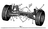
Figur 1 eine Hinterachse mit einem Hilfsrahmen 1 und daran befestigten Achselementen am Beispiel einer nicht angetriebenen Hinterachse. -
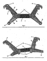
Figur 2 zeigt eine Ansicht aus derFigur 1 mit um die Achsen XYZ vorgenommener Verschwenkung, -
Figur 3 den Hilfsrahmen 1 aus einer derFigur 2 entsprechenden Perspektive, -
Figur 4 eine Ansicht des Hilfsrahmens 1 aus einer ähnlichen Sicht wieFigur 1 . - Die
Figuren 5 bis 7 zeigen den Längslenker gemäß dem Erfindungsgedanken, wobei -
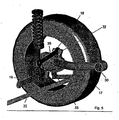
Figur 5 den Längslenker in eingebautem Zustand zeigt, -
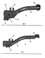
Figur 6 einen solchen in Ansicht und -
Figur 7 einen solchen in aufgeschnittenem Zustand. - Der Hilfsrahmen 1 besteht, mit Sicht auf die
Figur 1 und in Fahrtrichtung F gesehen, aus einem linken Hilfsrahmen-Seitenteil A und einem rechten Hilfsrahmen-Seitenteil B. Jedes der Seitenteile besitzt zumindest annähernd V-förmige Gestalt mit Schenkeln 2, 3 sowie 4, 5. Die beiden Schenkel treffen sich jeweils in ihrem Scheitelbereich 6, 7 und haben weiterhin einen Fußansatz 8,9 und somit insgesamt eine zumindest annähernd Y-förmige Gestalt. Die Fußansätze weisen in Richtung der Fahrzeuglängsachse, also aufeinander zu und haben die Profilierung eines Rechteckes 10, 11 in denen das Hilfsrahmen-Mittelteil C aufgenommen und mit den Profilen 8, 9 verschweißt ist. - An den Enden der V-förmigen Schenkel sind jeweils die Befestigungsstellen bzw. die Aufnahmen für den Durchgang von Befestigungsmittel zur Anlenkung des Hilfsrahmens an der Karosserie bzw. am Chassis des Fahrzeuges vorgesehen, und zwar besitzt das linke Hilfsrahmen-Seitenteil A eine vordere Befestigungsstelle 12, eine hintere Befestigungsstelle 13 und das rechte Hilfsrahmen-Seitenteil B eine vordere Befestigungsstelle 14 und eine hintere Befestigungsstelle 15. Der Hilfsrahmen besitzt weiterhin Aufnahmestellen für die Befestigung von Teilen der Hinterachse, die der Einfachheit wegen für das rechte und das linke Seitenteil mit jeweils gleichen Bezugszeichen versehen sind und zum Teil auch nur einmal dargestellt sind, nachdem es sich praktisch um spiegelbildliche Anordnungen handelt.
- An der Befestigungsstelle 16 ist der Längslenker 17 angelenkt, die oberen und unteren Querlenker 18, 19 sind an Befestigungsstellen 20, 21 angelenkt.
- Für den Stabilisator 22 sind, wie dies insbesondere im Zusammenhang mit den
Figuren 2 und3 hervorgeht, Befestigungsstellen 23 am unteren Bereich der Hilfsrahmen-Seitenteile vorgesehen. - Wie insbesondere im Zusammenhang mit den
Figuren 2 und3 ersichtlich ist, haben die Hilfsrahmen-Seitenteile einen U-förmigen Querschnitt mit Verstärkungsrippen 24, 25 und 26, 27, die zumindest im Wesentlichen zwischen den U-förmigen Schenkeln der Seitenteile verlaufen. Die Hilfsrahmen-Seitenteile A, B können in besonders günstiger Weise aus Aluminium-Druckguss bestehen, während das Hilfsrahmen-Mittelteil C zweckmäßigerweise ein Rechteck-Hohlprofil ist, das als Aluminium-Strangpressprofil hergestellt sein kann. - Durch Variierung der Länge des Hilfsrahmen-Mittelteiles C können in besonders preiswerter Weise Hinterachsen mit unterschiedlicher Spurbreite erzeugt werden.
- Zur Realisierung einer preiswerten Hinterachse insbesondere, jedoch nicht ausschließlich im Zusammenhang mit der vorliegenden Erfindung kann sich auch gemäß einem weiteren erfinderischen Gedanken ein Längslenker 17 gemäß den
Figuren 5 ,6 und 7 eignen, der mit seinem Auge 30 an der Befestigungsstelle 16 angelenkt sein kann und der an seinem gegenüberliegenden Ende den Radträgerbereich 31 einstückig angeformt hat. Der Bereich 32 dient zur Ablenkung des oberen Querlenkers 18 und die Anlenkstelle 33 zur Anlenkung des Stabilisators 22. In einer Aufnahmeöffnung 34 ist ein Stahl-Achszapfen 35 zur Aufnahme des Radlagers vorgesehen. Eine Befestigungsstelle 36 dient zur Anlenkung des Querlenkers 19. - Der Längslenker 17 mit seinem einstückig angeformten Radträgerbereich 31 kann in besonders günstiger Weise als Aluminium-Kokillen-Gussteil hergestellt sein, welches in seinem zwischen den Befestigungsstellen 30 und 34 liegenden Bereich 17a ein Aluminiumrohr, das eingegossen ist, enthält. Dadurch ist der entsprechende Längslenker als Hohlprofil für eine hohe Steifigkeit bei gleichzeitig geringer Masse und geringen Kosten ausgebildet.
Claims (16)
- Längslenker für einen Hitfsrahmen, wobei der Längslenker im Bereich zwischen seinem Anlenkpunkt am Hilfsrahmen und seinem einstückig angeformten Radträgerbereich ein Hohlprofil ist, dadurch gekennzeichnet, dass der Langslenker in diesem Bereich zwischen dem Anlenkpunkt und dem einstückig angeformten Radträgerbereich zusätzlich einen die Steifigkeit des Längstenkers erhöhenden Hohlkörper enthält.
- Längslenker nach Anspruch 1, dadurch gekennzeichnet, dass das Hohlprofil ein geschlossenes Profil ist.
- Längslenker nach einem der Ansprüche 1 bis 2, dadurch gekennzeichnet, dass der Längslenker ein Aluminium-Kokillen-Gussteil ist.
- Längslenker nach Anspruch 1, dadurch gekennzeichnet, dass der Hohlkörper in den Längslenker eingegossen ist.
- Längslenker nach Anspruch 4, dadurch gekennzeichnet, dass der Hohlkörper ein Al-Hohlprofil ist.
- Längslenker nach einem der Ansprüche 1 bis 5 dadurch gekennzeichnet, dass der Längslenker mit einem Hilfsrahmen, insbesondere einem Hinterachshilfsrahmen für Mehrtenker-Hinterachsen von Kraftfahrzeugen, verbunden ist, wobei der Hilfsrahmen aus zwei Hiffsrahmen-Seitenteiten besteht, die zumindest annähernd V-förmig ausgebildet sind, in einer Anordnung, dass deren Scheitelpunkte aufeinander gerichtet sind und über ein quer zur Fahrzeuglängsachse liegendes Hilfsrahmen-Mittelteil miteinander verbunden sind, wobei die Hilfsrahmen-Seitenteile und das Hilfsmhmen-Mittelteil Hohlprofile sind und die Hilfsrahmen-Seitenteile zumindest drei der nachfolgend angeführten Aufnahmen bzw. Ausnehmungen- die oberen Querlenker- die unteren Querlenker- den Stabilisator- die Längslenker- die Befestigung des Hilfsrahmens an der Karosserieaufweisen.
- Längslenker nach Anspruch 6 dadurch gekennzeichnet, dass die Förmigen Hilfsrahmerl-Seiterlteile einen U-förmigen Querschnitt aufweisen mit zwischen den Schenkeln verlaufenden Verstärkungsrippen.
- Längslenker nach Anspruch 6 oder 7; dadurch gekennzeichnet, dass die V-förmigen Seitenteile im Scheitelbereich den Fuß eines Y abgeformt haben mit einem dem Hiftsrahmen-Mitteltell entsprechenden Querschnitt.
- Längslenker nach einem der Ansprüche 6 bis 8, dadurch gekennzeichnet, dass das Hillsrahmen-Mitteltell in den Scheitelbereichen bzw. dem Fußbereich des Y aufgenommen ist.
- Längslenker nach einem der Ansprüche 6 bis 9, dadurch gekennzeichnet, dass das Hilfsrahmen-Mittelteil ein viereckiges Hohlprofil ist.
- Längslenker nach einem der Ansprüche 6 bis 10, dadurch gekennzeichnet, dass die V- bzw. Y-förmigen Hilfsrahmen-Seitenteile und der Hilfsrahmen-Mittelträger miteinander verschweißt sind.
- Längslenker nach einem der Ansprüche 6 bis 11, dadurch gekennzeichnet, dass die Hitfsrahmen-Seitenteile und/ oder das Hilferahmen-Miftelteil aus Leichtmetall bestehen.
- Längslenker nach Anspruch 12, dadurch gekennzeichnet, dass das Leichtmetall eine Al-Legierüng ist.
- Längslenker nach einem der Ansprüche 6 bis 13, dadurch gekennzeichnet, dass die Hilfsrahmen-Seitenteite Druckgussteile sind.
- Längslenker nach einem der Ansprüche 6 bis 14, dadurch gekennzeichnet, dass das Hilfsrahmen-Mittelteil ein Strangpressprofil ist.
- Längslenker nach einem der Ansprüche 6 bis 15, dadurch gekennzeichnet, dass die Ausnehmungen zur Befestigung des Hilfsrahmens an der Karosserie am Ende der Schenkel der Hilfsrahmen-Seilenteile vorgesehen sind.
Applications Claiming Priority (2)
| Application Number | Priority Date | Filing Date | Title |
|---|---|---|---|
| DE102005043764 | 2005-09-13 | ||
| EP06775942A EP1924485B1 (de) | 2005-09-13 | 2006-09-08 | Hilfsrahmen, insbesondere für kraftfahrzeuge |
Related Parent Applications (1)
| Application Number | Title | Priority Date | Filing Date |
|---|---|---|---|
| EP06775942.3 Division | 2006-09-08 |
Publications (3)
| Publication Number | Publication Date |
|---|---|
| EP2177423A2 EP2177423A2 (de) | 2010-04-21 |
| EP2177423A3 EP2177423A3 (de) | 2010-06-23 |
| EP2177423B1 true EP2177423B1 (de) | 2013-02-20 |
Family
ID=37565145
Family Applications (2)
| Application Number | Title | Priority Date | Filing Date |
|---|---|---|---|
| EP10001389A Not-in-force EP2177423B1 (de) | 2005-09-13 | 2006-09-08 | Längslenker für einen Hilfsrahmen |
| EP06775942A Not-in-force EP1924485B1 (de) | 2005-09-13 | 2006-09-08 | Hilfsrahmen, insbesondere für kraftfahrzeuge |
Family Applications After (1)
| Application Number | Title | Priority Date | Filing Date |
|---|---|---|---|
| EP06775942A Not-in-force EP1924485B1 (de) | 2005-09-13 | 2006-09-08 | Hilfsrahmen, insbesondere für kraftfahrzeuge |
Country Status (10)
| Country | Link |
|---|---|
| US (2) | US7938414B2 (de) |
| EP (2) | EP2177423B1 (de) |
| JP (1) | JP4856705B2 (de) |
| CN (2) | CN102019833A (de) |
| AT (1) | ATE489277T1 (de) |
| DE (3) | DE502006008396D1 (de) |
| FR (1) | FR2890641A1 (de) |
| IT (1) | ITMI20061750A1 (de) |
| NO (1) | NO20081756L (de) |
| WO (1) | WO2007031059A2 (de) |
Families Citing this family (31)
| Publication number | Priority date | Publication date | Assignee | Title |
|---|---|---|---|---|
| WO2007031059A2 (de) * | 2005-09-13 | 2007-03-22 | Ksm Castings Gmbh | Hilfsrahmen, insbesondere für kraftfahrzeuge |
| US8827028B2 (en) | 2006-07-28 | 2014-09-09 | Polaris Industries Inc. | Side-by-side ATV |
| US7819220B2 (en) | 2006-07-28 | 2010-10-26 | Polaris Industries Inc. | Side-by-side ATV |
| ATE537050T1 (de) * | 2006-12-29 | 2011-12-15 | Ksm Castings Gmbh | Achsträger für kfz |
| IT1394074B1 (it) * | 2008-06-11 | 2012-05-25 | Ksm Castings Gmbh | Elemento nodale |
| DE102009043474A1 (de) * | 2008-10-30 | 2010-05-12 | Ksm Castings Gmbh | Vorderachsträger für ein Kraftfahrzeug sowie Verfahren zu dessen Herstellung |
| JP5084883B2 (ja) * | 2009-12-28 | 2012-11-28 | 株式会社ヨロズ | サスペンションのサブフレーム |
| WO2012025096A1 (de) | 2010-06-04 | 2012-03-01 | Ksm Castings Gmbh | Längslenker für kraftfahrzeuge |
| DE102011077336A1 (de) * | 2011-06-10 | 2012-12-13 | Zf Friedrichshafen Ag | Radaufhängungselement, umfassend zumindest eine Tragstruktur und einen Lenker |
| DE102011106250A1 (de) * | 2011-07-01 | 2013-01-03 | Audi Ag | Hilfsrahmen für das Fahrzeugchassis von Kraftfahrzeugen |
| CN102358135A (zh) * | 2011-07-13 | 2012-02-22 | 江苏汤臣汽车零部件有限公司 | 一种载重汽车车桥平衡轴支承座 |
| DE112013005135A5 (de) * | 2012-10-24 | 2015-07-16 | Ksm Castings Group Gmbh | Modulares System für den Hinterrahmen eines Kraftfahrzeugs |
| JP6199587B2 (ja) * | 2012-12-14 | 2017-09-20 | ダイハツ工業株式会社 | 車両のサスペンション |
| WO2014092139A1 (ja) * | 2012-12-14 | 2014-06-19 | ダイハツ工業株式会社 | 車両のサスペンション |
| JP6009927B2 (ja) * | 2012-12-14 | 2016-10-19 | ダイハツ工業株式会社 | 車両のサスペンション |
| FR3006943B1 (fr) * | 2013-06-18 | 2016-02-26 | Peugeot Citroen Automobiles Sa | Procede de realisation d'un berceau avant de vehicule, et berceau avant de vehicule obtenu par ce procede. |
| DE102013218103A1 (de) * | 2013-09-10 | 2015-03-12 | Bayerische Motoren Werke Aktiengesellschaft | Hinterradaufhängung für ein Kraftfahrzeug |
| US9394002B2 (en) | 2014-03-20 | 2016-07-19 | Ford Global Technologies, Llc | Extruded metal sub-frame for a vehicle |
| KR101637287B1 (ko) * | 2014-09-02 | 2016-07-07 | 현대자동차 주식회사 | 서브 프레임용 마운팅 유닛 |
| JP6488598B2 (ja) * | 2014-09-05 | 2019-03-27 | スズキ株式会社 | サスペンションフレーム構造 |
| DE102016206649A1 (de) * | 2015-05-21 | 2016-11-24 | Ford Global Technologies, Llc | Hilfsrahmen für ein Fahrzeug |
| DE102016206646A1 (de) * | 2015-05-21 | 2016-11-24 | Ford Global Technologies, Llc | Hilfsrahmen für ein Fahrzeug |
| CN105128937A (zh) * | 2015-09-06 | 2015-12-09 | 上海友升铝业有限公司 | 铝合金副车架的转接支架 |
| FR3059630B1 (fr) | 2016-12-06 | 2020-02-14 | Renault S.A.S | Assemblage d'un berceau de vehicule sur caisse comportant une piece de fonderie |
| FR3059631B1 (fr) | 2016-12-06 | 2019-06-14 | Renault S.A.S | Dispositif de liaison entre un longeron en aluminium de vehicule et un bras de suspension |
| CN106739906B (zh) * | 2016-12-15 | 2018-03-30 | 吉林大学 | 一种碳纤维增强客车空气悬架c形梁结构及其设计方法 |
| US11379431B2 (en) * | 2019-12-09 | 2022-07-05 | Microsoft Technology Licensing, Llc | Write optimization in transactional data management systems |
| CN112319164A (zh) * | 2020-11-18 | 2021-02-05 | 芜湖禾田汽车工业有限公司 | 一种基于铸造铝合金的汽车悬挂系统 |
| GB2609254B (en) | 2021-07-27 | 2024-06-05 | Jaguar Land Rover Ltd | Fluid bump stop system |
| CN113400877B (zh) * | 2021-07-30 | 2022-04-08 | 奇瑞汽车股份有限公司 | 悬架系统及车辆 |
| CN114347740B (zh) * | 2021-12-31 | 2024-07-05 | 长葛市烁宇机械有限公司 | 一种高强度耐磨损的轮架 |
Citations (2)
| Publication number | Priority date | Publication date | Assignee | Title |
|---|---|---|---|---|
| DE4120894A1 (de) * | 1991-06-25 | 1993-01-14 | Bayerische Motoren Werke Ag | Einzelradaufhaengung fuer ein einzelnes hinteres rad eines fahrzeugs |
| EP1262396A1 (de) * | 1997-03-01 | 2002-12-04 | Adam Opel Ag | Hilfsrahmen für die Vorder- oder Hinterradaufhängung eines Kraftfahrzeuges |
Family Cites Families (52)
| Publication number | Priority date | Publication date | Assignee | Title |
|---|---|---|---|---|
| DE2740948A1 (de) * | 1977-09-10 | 1979-03-22 | Volkswagenwerk Ag | Verbundlenkerachse fuer kraftfahrzeuge |
| US4429900A (en) * | 1980-11-06 | 1984-02-07 | Feher Joseph S | Automotive suspension system for maintaining the rear wheels substantially parallel to one another throughout use |
| EP0302226B1 (de) * | 1983-09-02 | 1993-11-24 | Mazda Motor Corporation | Hinterradaufhängungssystem für Fahrzeuge |
| DE3507081C1 (de) * | 1985-02-28 | 1986-06-26 | Bayerische Motoren Werke AG, 8000 München | Hinterradaufhaengung fuer Kraftfahrzeuge,insbesondere fuer angetriebene Hinterraeder |
| JPS6367439A (ja) * | 1986-09-10 | 1988-03-26 | Mazda Motor Corp | 車両の防振装置 |
| IT1212162B (it) * | 1987-12-30 | 1989-11-08 | Fiat Auto Spa | Sospensione posteriore per autoveicoli del tipo a ruote indipendenti a quadrilateri trasversali |
| JP2595329B2 (ja) * | 1988-10-16 | 1997-04-02 | 富士重工業株式会社 | 薄肉鋳造製サスペンション用ア―ムの製造法 |
| JPH02106974A (ja) * | 1988-10-17 | 1990-04-19 | Nec Corp | 高耐圧半導体装置 |
| EP0441818B1 (de) * | 1988-11-05 | 1993-08-11 | Volkswagen Aktiengesellschaft | Am Fahrzeugaufbau eines Kraftfahrzeugs lösbar befestigbare Baueinheit |
| JPH02106974U (de) * | 1989-02-09 | 1990-08-24 | ||
| DE3927987A1 (de) | 1989-08-24 | 1991-02-28 | Bayerische Motoren Werke Ag | Hilfsrahmen fuer kraftfahrzeuge |
| DE4011948A1 (de) | 1990-04-12 | 1991-10-17 | Alcan Gmbh | Verbundgussverfahren |
| DE4120984A1 (de) | 1990-06-26 | 1992-01-09 | Mazda Motor | Sensor mit einem magnetfilm und verfahren zu dessen herstellung |
| JP2707860B2 (ja) * | 1991-03-26 | 1998-02-04 | トヨタ自動車株式会社 | 車体のフレーム構造 |
| JP2924306B2 (ja) * | 1991-06-03 | 1999-07-26 | 日産自動車株式会社 | 車輪独立懸架装置 |
| DE4129538C2 (de) * | 1991-09-05 | 1993-11-18 | Porsche Ag | Fahrschemel für ein Kraftfahrzeug |
| EP0594131A1 (de) * | 1992-10-21 | 1994-04-27 | The Budd Company | Verbund-Fahrgestell und Herstellungsverfahren |
| US5507888A (en) * | 1993-03-18 | 1996-04-16 | Aluminum Company Of America | Bicycle frames and aluminum alloy tubing therefor and methods for their production |
| US5342459A (en) * | 1993-03-18 | 1994-08-30 | Aluminum Company Of America | Aluminum alloy extruded and cold worked products having fine grain structure and their manufacture |
| DE4343841C3 (de) | 1993-12-22 | 2000-09-14 | Daimler Chrysler Ag | Verfahren zum Herstellen eines Achslenkers |
| JPH08282530A (ja) * | 1995-04-10 | 1996-10-29 | Nissan Motor Co Ltd | 自動車のサブフレーム構造 |
| JPH09193633A (ja) * | 1996-01-23 | 1997-07-29 | Mitsubishi Materials Corp | L字状チャンネル構造体 |
| NL1002490C2 (nl) * | 1996-02-29 | 1997-09-01 | Netherlands Car Bv | Motorvoertuig. |
| DE19653542B4 (de) | 1996-12-20 | 2006-03-09 | Audi Ag | Aus einer Leichtmetall-Legierung gegossenes Bauteil |
| DE19708421A1 (de) * | 1997-03-01 | 1998-09-03 | Opel Adam Ag | Hilfsrahmen für die Vorder- oder Hinterradaufhängung eines Kraftfahrzeuges |
| JP3945852B2 (ja) * | 1997-03-18 | 2007-07-18 | 株式会社神戸製鋼所 | 自動車構造部材用継手構造 |
| DE19730404B4 (de) * | 1997-07-16 | 2005-04-21 | Daimlerchrysler Ag | Hilfsrahmen für Kraftfahrzeuge |
| JPH11222152A (ja) * | 1998-02-05 | 1999-08-17 | Kobe Steel Ltd | 自動車サスペンションメンバの製造方法 |
| DE19911121A1 (de) * | 1998-03-13 | 1999-09-16 | Tokai Rubber Ind Ltd | Lenkerarm, insbesondere für ein Kraftfahrzeug |
| US6381850B1 (en) * | 1999-03-09 | 2002-05-07 | Ted Warner | Wire stripping and preparation apparatus |
| JP3603672B2 (ja) | 1999-06-11 | 2004-12-22 | 日産自動車株式会社 | サスペンションメンバ構造 |
| JP3921314B2 (ja) * | 1999-09-03 | 2007-05-30 | 株式会社神戸製鋼所 | 衝撃破壊強度に優れたアルミニウム合金鋳造材およびその製造方法 |
| FR2798355B1 (fr) * | 1999-09-15 | 2001-12-14 | Valeo Thermique Moteur Sa | Element de structure composite, notamment support de face avant pour vehicule |
| JP3407721B2 (ja) * | 1999-10-28 | 2003-05-19 | トヨタ自動車株式会社 | フロントサスペンションメンバ |
| JP2001271861A (ja) * | 2000-03-24 | 2001-10-05 | Tokai Rubber Ind Ltd | 車両用アーム部材 |
| US6851691B2 (en) * | 2000-08-22 | 2005-02-08 | Bombardier Recreational Products Inc. | Suspension system for an all terrain vehicle |
| JP2002166714A (ja) | 2000-11-30 | 2002-06-11 | Suzuki Motor Corp | サスペンションアーム |
| US6866295B2 (en) * | 2000-12-28 | 2005-03-15 | Dana Corporation | Modular cast independent front suspension subframe |
| JP4007774B2 (ja) * | 2001-06-15 | 2007-11-14 | 本田技研工業株式会社 | 自動車の車体フレーム構造 |
| JP2003034112A (ja) | 2001-07-19 | 2003-02-04 | Bridgestone Corp | 自動車サスペンション装置用案内部材の製造方法 |
| US6648351B1 (en) * | 2001-10-22 | 2003-11-18 | Hayes Lemmerz International, Inc. | Cast aluminum rear subframe control arm articulations |
| DE10231377B3 (de) * | 2002-07-11 | 2004-01-15 | Daimlerchrysler Ag | Fahrzeugstarrachse mit integrierten Länglenkern |
| US6945547B2 (en) * | 2002-09-09 | 2005-09-20 | Delphi Technologies, Inc. | Multi-link independent rear suspension assembly |
| US7010950B2 (en) * | 2003-01-17 | 2006-03-14 | Visteon Global Technologies, Inc. | Suspension component having localized material strengthening |
| US6755429B1 (en) * | 2003-05-06 | 2004-06-29 | Ford Global Technologies, Llc | Independent suspension for rear wheels of automotive vehicle |
| JP4273316B2 (ja) * | 2003-08-20 | 2009-06-03 | トヨタ自動車株式会社 | サスペンションメンバーおよびその製造方法 |
| CN2651119Y (zh) * | 2003-10-16 | 2004-10-27 | 上汽集团奇瑞汽车有限公司 | 副车架 |
| DE20319147U1 (de) * | 2003-12-09 | 2004-04-01 | Zf Friedrichshafen Ag | Radträgereinheit für ein Kraftfahrzeug |
| JP4247902B2 (ja) * | 2004-03-31 | 2009-04-02 | 本田技研工業株式会社 | ブッシュ取付構造 |
| US20060071441A1 (en) * | 2004-10-06 | 2006-04-06 | William Mathis | Lower control arm kit for vehicle with four link rear suspension |
| WO2007031059A2 (de) * | 2005-09-13 | 2007-03-22 | Ksm Castings Gmbh | Hilfsrahmen, insbesondere für kraftfahrzeuge |
| JP4193837B2 (ja) * | 2005-11-04 | 2008-12-10 | トヨタ自動車株式会社 | トレーリング・アーム式サスペンション構造及びアクスルキャリア |
-
2006
- 2006-09-08 WO PCT/DE2006/001581 patent/WO2007031059A2/de not_active Ceased
- 2006-09-08 CN CN2010105139633A patent/CN102019833A/zh active Pending
- 2006-09-08 EP EP10001389A patent/EP2177423B1/de not_active Not-in-force
- 2006-09-08 US US11/990,312 patent/US7938414B2/en not_active Expired - Fee Related
- 2006-09-08 AT AT06775942T patent/ATE489277T1/de active
- 2006-09-08 DE DE502006008396T patent/DE502006008396D1/de active Active
- 2006-09-08 JP JP2008528341A patent/JP4856705B2/ja not_active Expired - Fee Related
- 2006-09-08 EP EP06775942A patent/EP1924485B1/de not_active Not-in-force
- 2006-09-08 DE DE102006062889.6A patent/DE102006062889B4/de not_active Expired - Fee Related
- 2006-09-08 DE DE112006003073T patent/DE112006003073A5/de not_active Withdrawn
- 2006-09-08 CN CN2006800335992A patent/CN101263041B/zh not_active Expired - Fee Related
- 2006-09-13 FR FR0607993A patent/FR2890641A1/fr active Pending
- 2006-09-13 IT IT001750A patent/ITMI20061750A1/it unknown
-
2008
- 2008-04-10 NO NO20081756A patent/NO20081756L/no not_active Application Discontinuation
-
2011
- 2011-03-09 US US12/932,899 patent/US8393627B2/en not_active Expired - Fee Related
Patent Citations (2)
| Publication number | Priority date | Publication date | Assignee | Title |
|---|---|---|---|---|
| DE4120894A1 (de) * | 1991-06-25 | 1993-01-14 | Bayerische Motoren Werke Ag | Einzelradaufhaengung fuer ein einzelnes hinteres rad eines fahrzeugs |
| EP1262396A1 (de) * | 1997-03-01 | 2002-12-04 | Adam Opel Ag | Hilfsrahmen für die Vorder- oder Hinterradaufhängung eines Kraftfahrzeuges |
Also Published As
| Publication number | Publication date |
|---|---|
| EP1924485B1 (de) | 2010-11-24 |
| EP2177423A2 (de) | 2010-04-21 |
| NO20081756L (no) | 2008-05-30 |
| CN101263041B (zh) | 2011-01-12 |
| EP1924485A2 (de) | 2008-05-28 |
| US20100133800A1 (en) | 2010-06-03 |
| WO2007031059A3 (de) | 2007-05-24 |
| FR2890641A1 (fr) | 2007-03-16 |
| CN102019833A (zh) | 2011-04-20 |
| WO2007031059A2 (de) | 2007-03-22 |
| DE102006062889B4 (de) | 2014-06-26 |
| CN101263041A (zh) | 2008-09-10 |
| JP4856705B2 (ja) | 2012-01-18 |
| DE112006003073A5 (de) | 2008-09-11 |
| JP2009505889A (ja) | 2009-02-12 |
| US7938414B2 (en) | 2011-05-10 |
| ATE489277T1 (de) | 2010-12-15 |
| EP2177423A3 (de) | 2010-06-23 |
| DE502006008396D1 (de) | 2011-01-05 |
| ITMI20061750A1 (it) | 2007-03-14 |
| US8393627B2 (en) | 2013-03-12 |
| US20110163513A1 (en) | 2011-07-07 |
Similar Documents
| Publication | Publication Date | Title |
|---|---|---|
| EP2177423B1 (de) | Längslenker für einen Hilfsrahmen | |
| DE102006062840B4 (de) | Vorderachsträger, insbesondere für Kraftfahrzeuge | |
| EP0861744B1 (de) | Verbundlenker-Hinterachse für Kraftfahrzeuge | |
| EP0146716A2 (de) | Wagenkasten | |
| DE4129538A1 (de) | Fahrschemel fuer ein kraftfahrzeug | |
| DE2536060A1 (de) | Radaufhaengung fuer kraftfahrzeuge | |
| DE102009004310A1 (de) | Fahrschemel, insbesondere Vorderachsträger | |
| EP2114753B1 (de) | Achsträger für kfz | |
| EP0940320B1 (de) | Fahrgestell eines schweren Nutzfahrzeuges | |
| DE69306902T2 (de) | Aufhängungsarm für ein Kraftfahrzeug | |
| DE69426991T2 (de) | Längsarmaufhängung | |
| DE19809279A1 (de) | Fahrgestell eines schweren Nutzfahrzeuges | |
| DE10254693A1 (de) | Vorderwagenstruktur | |
| DE102006042376A1 (de) | Hilfsrahmen, insbesondere für Kraftfahrzeuge | |
| DE102006010130B4 (de) | Hilfsrahmen, insbesondere für Kraftfahrzeuge | |
| EP0940322B1 (de) | Fahrgestell eines schweren Nutzfahrzeuges | |
| DE10122998A1 (de) | Verbundlenkerachse und Verfahren zur Herstellung eines Querträgers | |
| EP0940324A1 (de) | Fahrgestell eines schweren Nutzfahrzeuges | |
| EP0940325A1 (de) | Fahrgestell eines schweren Nutzfahrzeuges | |
| EP0940323B1 (de) | Fahrgestell eines schweren Nutzfahrzeuges | |
| DE202015102551U1 (de) | Achsanordnung | |
| EP0940321B1 (de) | Fahrgestell eines schweren Nutzfahrzeuges | |
| DE10040656A1 (de) | Liftbare Achse eines Nutzfahrzeuges | |
| DE102008045924A1 (de) | Tragstruktur für einen Rahmen eines Nutzfahrzeugs | |
| DE10343583A1 (de) | Verbundlenker-Fahrzeugachse in Bauart als ein- oder mehrteiliger Formkörper |
Legal Events
| Date | Code | Title | Description |
|---|---|---|---|
| PUAI | Public reference made under article 153(3) epc to a published international application that has entered the european phase |
Free format text: ORIGINAL CODE: 0009012 |
|
| AC | Divisional application: reference to earlier application |
Ref document number: 1924485 Country of ref document: EP Kind code of ref document: P |
|
| AK | Designated contracting states |
Kind code of ref document: A2 Designated state(s): AT BE BG CH CY CZ DE DK EE ES FI FR GB GR HU IE IS IT LI LT LU LV MC NL PL PT RO SE SI SK TR |
|
| AX | Request for extension of the european patent |
Extension state: AL BA HR MK RS |
|
| PUAL | Search report despatched |
Free format text: ORIGINAL CODE: 0009013 |
|
| RIC1 | Information provided on ipc code assigned before grant |
Ipc: B60G 7/00 20060101ALI20100506BHEP Ipc: B62D 21/11 20060101AFI20100305BHEP |
|
| AK | Designated contracting states |
Kind code of ref document: A3 Designated state(s): AT BE BG CH CY CZ DE DK EE ES FI FR GB GR HU IE IS IT LI LT LU LV MC NL PL PT RO SE SI SK TR |
|
| AX | Request for extension of the european patent |
Extension state: AL BA HR MK RS |
|
| 17P | Request for examination filed |
Effective date: 20101214 |
|
| 17Q | First examination report despatched |
Effective date: 20110114 |
|
| RAP1 | Party data changed (applicant data changed or rights of an application transferred) |
Owner name: KSM CASTINGS GMBH |
|
| REG | Reference to a national code |
Ref country code: DE Ref legal event code: R079 Ref document number: 502006012527 Country of ref document: DE Free format text: PREVIOUS MAIN CLASS: B62D0021110000 Ipc: B60G0003200000 |
|
| GRAP | Despatch of communication of intention to grant a patent |
Free format text: ORIGINAL CODE: EPIDOSNIGR1 |
|
| RIC1 | Information provided on ipc code assigned before grant |
Ipc: B62D 21/11 20060101ALI20120810BHEP Ipc: B60G 3/20 20060101AFI20120810BHEP Ipc: B60G 3/22 20060101ALI20120810BHEP Ipc: B60G 7/00 20060101ALI20120810BHEP |
|
| RAP1 | Party data changed (applicant data changed or rights of an application transferred) |
Owner name: KSM CASTINGS GROUP GMBH |
|
| GRAP | Despatch of communication of intention to grant a patent |
Free format text: ORIGINAL CODE: EPIDOSNIGR1 |
|
| GRAC | Information related to communication of intention to grant a patent modified |
Free format text: ORIGINAL CODE: EPIDOSCIGR1 |
|
| GRAC | Information related to communication of intention to grant a patent modified |
Free format text: ORIGINAL CODE: EPIDOSCIGR1 |
|
| GRAS | Grant fee paid |
Free format text: ORIGINAL CODE: EPIDOSNIGR3 |
|
| GRAA | (expected) grant |
Free format text: ORIGINAL CODE: 0009210 |
|
| AC | Divisional application: reference to earlier application |
Ref document number: 1924485 Country of ref document: EP Kind code of ref document: P |
|
| AK | Designated contracting states |
Kind code of ref document: B1 Designated state(s): AT BE BG CH CY CZ DE DK EE ES FI FR GB GR HU IE IS IT LI LT LU LV MC NL PL PT RO SE SI SK TR |
|
| REG | Reference to a national code |
Ref country code: GB Ref legal event code: FG4D Free format text: NOT ENGLISH |
|
| REG | Reference to a national code |
Ref country code: CH Ref legal event code: EP |
|
| REG | Reference to a national code |
Ref country code: AT Ref legal event code: REF Ref document number: 597381 Country of ref document: AT Kind code of ref document: T Effective date: 20130315 |
|
| REG | Reference to a national code |
Ref country code: IE Ref legal event code: FG4D Free format text: LANGUAGE OF EP DOCUMENT: GERMAN |
|
| REG | Reference to a national code |
Ref country code: DE Ref legal event code: R096 Ref document number: 502006012527 Country of ref document: DE Effective date: 20130418 |
|
| REG | Reference to a national code |
Ref country code: NL Ref legal event code: VDEP Effective date: 20130220 |
|
| REG | Reference to a national code |
Ref country code: LT Ref legal event code: MG4D |
|
| PG25 | Lapsed in a contracting state [announced via postgrant information from national office to epo] |
Ref country code: ES Free format text: LAPSE BECAUSE OF FAILURE TO SUBMIT A TRANSLATION OF THE DESCRIPTION OR TO PAY THE FEE WITHIN THE PRESCRIBED TIME-LIMIT Effective date: 20130531 Ref country code: BG Free format text: LAPSE BECAUSE OF FAILURE TO SUBMIT A TRANSLATION OF THE DESCRIPTION OR TO PAY THE FEE WITHIN THE PRESCRIBED TIME-LIMIT Effective date: 20130520 Ref country code: LT Free format text: LAPSE BECAUSE OF FAILURE TO SUBMIT A TRANSLATION OF THE DESCRIPTION OR TO PAY THE FEE WITHIN THE PRESCRIBED TIME-LIMIT Effective date: 20130220 Ref country code: IS Free format text: LAPSE BECAUSE OF FAILURE TO SUBMIT A TRANSLATION OF THE DESCRIPTION OR TO PAY THE FEE WITHIN THE PRESCRIBED TIME-LIMIT Effective date: 20130620 Ref country code: SE Free format text: LAPSE BECAUSE OF FAILURE TO SUBMIT A TRANSLATION OF THE DESCRIPTION OR TO PAY THE FEE WITHIN THE PRESCRIBED TIME-LIMIT Effective date: 20130220 |
|
| PG25 | Lapsed in a contracting state [announced via postgrant information from national office to epo] |
Ref country code: LV Free format text: LAPSE BECAUSE OF FAILURE TO SUBMIT A TRANSLATION OF THE DESCRIPTION OR TO PAY THE FEE WITHIN THE PRESCRIBED TIME-LIMIT Effective date: 20130220 Ref country code: PL Free format text: LAPSE BECAUSE OF FAILURE TO SUBMIT A TRANSLATION OF THE DESCRIPTION OR TO PAY THE FEE WITHIN THE PRESCRIBED TIME-LIMIT Effective date: 20130220 Ref country code: FI Free format text: LAPSE BECAUSE OF FAILURE TO SUBMIT A TRANSLATION OF THE DESCRIPTION OR TO PAY THE FEE WITHIN THE PRESCRIBED TIME-LIMIT Effective date: 20130220 Ref country code: GR Free format text: LAPSE BECAUSE OF FAILURE TO SUBMIT A TRANSLATION OF THE DESCRIPTION OR TO PAY THE FEE WITHIN THE PRESCRIBED TIME-LIMIT Effective date: 20130521 Ref country code: PT Free format text: LAPSE BECAUSE OF FAILURE TO SUBMIT A TRANSLATION OF THE DESCRIPTION OR TO PAY THE FEE WITHIN THE PRESCRIBED TIME-LIMIT Effective date: 20130620 Ref country code: SI Free format text: LAPSE BECAUSE OF FAILURE TO SUBMIT A TRANSLATION OF THE DESCRIPTION OR TO PAY THE FEE WITHIN THE PRESCRIBED TIME-LIMIT Effective date: 20130220 |
|
| PG25 | Lapsed in a contracting state [announced via postgrant information from national office to epo] |
Ref country code: SK Free format text: LAPSE BECAUSE OF FAILURE TO SUBMIT A TRANSLATION OF THE DESCRIPTION OR TO PAY THE FEE WITHIN THE PRESCRIBED TIME-LIMIT Effective date: 20130220 Ref country code: DK Free format text: LAPSE BECAUSE OF FAILURE TO SUBMIT A TRANSLATION OF THE DESCRIPTION OR TO PAY THE FEE WITHIN THE PRESCRIBED TIME-LIMIT Effective date: 20130220 Ref country code: CZ Free format text: LAPSE BECAUSE OF FAILURE TO SUBMIT A TRANSLATION OF THE DESCRIPTION OR TO PAY THE FEE WITHIN THE PRESCRIBED TIME-LIMIT Effective date: 20130220 Ref country code: NL Free format text: LAPSE BECAUSE OF FAILURE TO SUBMIT A TRANSLATION OF THE DESCRIPTION OR TO PAY THE FEE WITHIN THE PRESCRIBED TIME-LIMIT Effective date: 20130220 Ref country code: RO Free format text: LAPSE BECAUSE OF FAILURE TO SUBMIT A TRANSLATION OF THE DESCRIPTION OR TO PAY THE FEE WITHIN THE PRESCRIBED TIME-LIMIT Effective date: 20130220 Ref country code: EE Free format text: LAPSE BECAUSE OF FAILURE TO SUBMIT A TRANSLATION OF THE DESCRIPTION OR TO PAY THE FEE WITHIN THE PRESCRIBED TIME-LIMIT Effective date: 20130220 |
|
| PLBE | No opposition filed within time limit |
Free format text: ORIGINAL CODE: 0009261 |
|
| STAA | Information on the status of an ep patent application or granted ep patent |
Free format text: STATUS: NO OPPOSITION FILED WITHIN TIME LIMIT |
|
| PG25 | Lapsed in a contracting state [announced via postgrant information from national office to epo] |
Ref country code: IT Free format text: LAPSE BECAUSE OF FAILURE TO SUBMIT A TRANSLATION OF THE DESCRIPTION OR TO PAY THE FEE WITHIN THE PRESCRIBED TIME-LIMIT Effective date: 20130220 |
|
| 26N | No opposition filed |
Effective date: 20131121 |
|
| REG | Reference to a national code |
Ref country code: DE Ref legal event code: R097 Ref document number: 502006012527 Country of ref document: DE Effective date: 20131121 |
|
| BERE | Be: lapsed |
Owner name: KSM CASTINGS GROUP G.M.B.H. Effective date: 20130930 |
|
| PG25 | Lapsed in a contracting state [announced via postgrant information from national office to epo] |
Ref country code: MC Free format text: LAPSE BECAUSE OF FAILURE TO SUBMIT A TRANSLATION OF THE DESCRIPTION OR TO PAY THE FEE WITHIN THE PRESCRIBED TIME-LIMIT Effective date: 20130220 |
|
| REG | Reference to a national code |
Ref country code: CH Ref legal event code: PL |
|
| GBPC | Gb: european patent ceased through non-payment of renewal fee |
Effective date: 20130908 |
|
| REG | Reference to a national code |
Ref country code: FR Ref legal event code: ST Effective date: 20140530 |
|
| REG | Reference to a national code |
Ref country code: IE Ref legal event code: MM4A |
|
| PG25 | Lapsed in a contracting state [announced via postgrant information from national office to epo] |
Ref country code: IE Free format text: LAPSE BECAUSE OF NON-PAYMENT OF DUE FEES Effective date: 20130908 Ref country code: GB Free format text: LAPSE BECAUSE OF NON-PAYMENT OF DUE FEES Effective date: 20130908 Ref country code: BE Free format text: LAPSE BECAUSE OF NON-PAYMENT OF DUE FEES Effective date: 20130930 Ref country code: CH Free format text: LAPSE BECAUSE OF NON-PAYMENT OF DUE FEES Effective date: 20130930 Ref country code: LI Free format text: LAPSE BECAUSE OF NON-PAYMENT OF DUE FEES Effective date: 20130930 |
|
| PG25 | Lapsed in a contracting state [announced via postgrant information from national office to epo] |
Ref country code: FR Free format text: LAPSE BECAUSE OF NON-PAYMENT OF DUE FEES Effective date: 20130930 |
|
| REG | Reference to a national code |
Ref country code: AT Ref legal event code: MM01 Ref document number: 597381 Country of ref document: AT Kind code of ref document: T Effective date: 20130908 |
|
| PG25 | Lapsed in a contracting state [announced via postgrant information from national office to epo] |
Ref country code: AT Free format text: LAPSE BECAUSE OF NON-PAYMENT OF DUE FEES Effective date: 20130908 |
|
| PG25 | Lapsed in a contracting state [announced via postgrant information from national office to epo] |
Ref country code: TR Free format text: LAPSE BECAUSE OF FAILURE TO SUBMIT A TRANSLATION OF THE DESCRIPTION OR TO PAY THE FEE WITHIN THE PRESCRIBED TIME-LIMIT Effective date: 20130220 Ref country code: CY Free format text: LAPSE BECAUSE OF FAILURE TO SUBMIT A TRANSLATION OF THE DESCRIPTION OR TO PAY THE FEE WITHIN THE PRESCRIBED TIME-LIMIT Effective date: 20130220 |
|
| PG25 | Lapsed in a contracting state [announced via postgrant information from national office to epo] |
Ref country code: LU Free format text: LAPSE BECAUSE OF NON-PAYMENT OF DUE FEES Effective date: 20130908 Ref country code: HU Free format text: LAPSE BECAUSE OF FAILURE TO SUBMIT A TRANSLATION OF THE DESCRIPTION OR TO PAY THE FEE WITHIN THE PRESCRIBED TIME-LIMIT; INVALID AB INITIO Effective date: 20060908 |
|
| REG | Reference to a national code |
Ref country code: DE Ref legal event code: R082 Ref document number: 502006012527 Country of ref document: DE |
|
| PGFP | Annual fee paid to national office [announced via postgrant information from national office to epo] |
Ref country code: DE Payment date: 20181130 Year of fee payment: 13 |
|
| REG | Reference to a national code |
Ref country code: DE Ref legal event code: R119 Ref document number: 502006012527 Country of ref document: DE |
|
| PG25 | Lapsed in a contracting state [announced via postgrant information from national office to epo] |
Ref country code: DE Free format text: LAPSE BECAUSE OF NON-PAYMENT OF DUE FEES Effective date: 20200401 |