EP2177776B1 - Assemblage comprenant un élément de fixation et un élément en tôle et procédé de fabrication d'un tel élément d'ensemble - Google Patents
Assemblage comprenant un élément de fixation et un élément en tôle et procédé de fabrication d'un tel élément d'ensemble Download PDFInfo
- Publication number
- EP2177776B1 EP2177776B1 EP09013045.1A EP09013045A EP2177776B1 EP 2177776 B1 EP2177776 B1 EP 2177776B1 EP 09013045 A EP09013045 A EP 09013045A EP 2177776 B1 EP2177776 B1 EP 2177776B1
- Authority
- EP
- European Patent Office
- Prior art keywords
- sheet metal
- metal part
- hole
- diameter
- rivet
- Prior art date
- Legal status (The legal status is an assumption and is not a legal conclusion. Google has not performed a legal analysis and makes no representation as to the accuracy of the status listed.)
- Active
Links
Images


Classifications
-
- F—MECHANICAL ENGINEERING; LIGHTING; HEATING; WEAPONS; BLASTING
- F16—ENGINEERING ELEMENTS AND UNITS; GENERAL MEASURES FOR PRODUCING AND MAINTAINING EFFECTIVE FUNCTIONING OF MACHINES OR INSTALLATIONS; THERMAL INSULATION IN GENERAL
- F16B—DEVICES FOR FASTENING OR SECURING CONSTRUCTIONAL ELEMENTS OR MACHINE PARTS TOGETHER, e.g. NAILS, BOLTS, CIRCLIPS, CLAMPS, CLIPS OR WEDGES; JOINTS OR JOINTING
- F16B19/00—Bolts without screw-thread; Pins, including deformable elements; Rivets
- F16B19/04—Rivets; Spigots or the like fastened by riveting
-
- F—MECHANICAL ENGINEERING; LIGHTING; HEATING; WEAPONS; BLASTING
- F16—ENGINEERING ELEMENTS AND UNITS; GENERAL MEASURES FOR PRODUCING AND MAINTAINING EFFECTIVE FUNCTIONING OF MACHINES OR INSTALLATIONS; THERMAL INSULATION IN GENERAL
- F16B—DEVICES FOR FASTENING OR SECURING CONSTRUCTIONAL ELEMENTS OR MACHINE PARTS TOGETHER, e.g. NAILS, BOLTS, CIRCLIPS, CLAMPS, CLIPS OR WEDGES; JOINTS OR JOINTING
- F16B37/00—Nuts or like thread-engaging members
- F16B37/04—Devices for fastening nuts to surfaces, e.g. sheets, plates
- F16B37/06—Devices for fastening nuts to surfaces, e.g. sheets, plates by means of welding or riveting
- F16B37/062—Devices for fastening nuts to surfaces, e.g. sheets, plates by means of welding or riveting by means of riveting
- F16B37/065—Devices for fastening nuts to surfaces, e.g. sheets, plates by means of welding or riveting by means of riveting by deforming the material of the nut
-
- B—PERFORMING OPERATIONS; TRANSPORTING
- B23—MACHINE TOOLS; METAL-WORKING NOT OTHERWISE PROVIDED FOR
- B23P—METAL-WORKING NOT OTHERWISE PROVIDED FOR; COMBINED OPERATIONS; UNIVERSAL MACHINE TOOLS
- B23P15/00—Making specific metal objects by operations not covered by a single other subclass or a group in this subclass
-
- F—MECHANICAL ENGINEERING; LIGHTING; HEATING; WEAPONS; BLASTING
- F16—ENGINEERING ELEMENTS AND UNITS; GENERAL MEASURES FOR PRODUCING AND MAINTAINING EFFECTIVE FUNCTIONING OF MACHINES OR INSTALLATIONS; THERMAL INSULATION IN GENERAL
- F16B—DEVICES FOR FASTENING OR SECURING CONSTRUCTIONAL ELEMENTS OR MACHINE PARTS TOGETHER, e.g. NAILS, BOLTS, CIRCLIPS, CLAMPS, CLIPS OR WEDGES; JOINTS OR JOINTING
- F16B19/00—Bolts without screw-thread; Pins, including deformable elements; Rivets
-
- F—MECHANICAL ENGINEERING; LIGHTING; HEATING; WEAPONS; BLASTING
- F16—ENGINEERING ELEMENTS AND UNITS; GENERAL MEASURES FOR PRODUCING AND MAINTAINING EFFECTIVE FUNCTIONING OF MACHINES OR INSTALLATIONS; THERMAL INSULATION IN GENERAL
- F16B—DEVICES FOR FASTENING OR SECURING CONSTRUCTIONAL ELEMENTS OR MACHINE PARTS TOGETHER, e.g. NAILS, BOLTS, CIRCLIPS, CLAMPS, CLIPS OR WEDGES; JOINTS OR JOINTING
- F16B37/00—Nuts or like thread-engaging members
-
- Y—GENERAL TAGGING OF NEW TECHNOLOGICAL DEVELOPMENTS; GENERAL TAGGING OF CROSS-SECTIONAL TECHNOLOGIES SPANNING OVER SEVERAL SECTIONS OF THE IPC; TECHNICAL SUBJECTS COVERED BY FORMER USPC CROSS-REFERENCE ART COLLECTIONS [XRACs] AND DIGESTS
- Y10—TECHNICAL SUBJECTS COVERED BY FORMER USPC
- Y10T—TECHNICAL SUBJECTS COVERED BY FORMER US CLASSIFICATION
- Y10T29/00—Metal working
- Y10T29/49—Method of mechanical manufacture
- Y10T29/49826—Assembling or joining
- Y10T29/49908—Joining by deforming
- Y10T29/49938—Radially expanding part in cavity, aperture, or hollow body
- Y10T29/49943—Riveting
-
- Y—GENERAL TAGGING OF NEW TECHNOLOGICAL DEVELOPMENTS; GENERAL TAGGING OF CROSS-SECTIONAL TECHNOLOGIES SPANNING OVER SEVERAL SECTIONS OF THE IPC; TECHNICAL SUBJECTS COVERED BY FORMER USPC CROSS-REFERENCE ART COLLECTIONS [XRACs] AND DIGESTS
- Y10—TECHNICAL SUBJECTS COVERED BY FORMER USPC
- Y10T—TECHNICAL SUBJECTS COVERED BY FORMER US CLASSIFICATION
- Y10T29/00—Metal working
- Y10T29/49—Method of mechanical manufacture
- Y10T29/49826—Assembling or joining
- Y10T29/49947—Assembling or joining by applying separate fastener
- Y10T29/49948—Multipart cooperating fastener [e.g., bolt and nut]
-
- Y—GENERAL TAGGING OF NEW TECHNOLOGICAL DEVELOPMENTS; GENERAL TAGGING OF CROSS-SECTIONAL TECHNOLOGIES SPANNING OVER SEVERAL SECTIONS OF THE IPC; TECHNICAL SUBJECTS COVERED BY FORMER USPC CROSS-REFERENCE ART COLLECTIONS [XRACs] AND DIGESTS
- Y10—TECHNICAL SUBJECTS COVERED BY FORMER USPC
- Y10T—TECHNICAL SUBJECTS COVERED BY FORMER US CLASSIFICATION
- Y10T29/00—Metal working
- Y10T29/49—Method of mechanical manufacture
- Y10T29/49826—Assembling or joining
- Y10T29/49947—Assembling or joining by applying separate fastener
- Y10T29/49954—Fastener deformed after application
- Y10T29/49956—Riveting
-
- Y—GENERAL TAGGING OF NEW TECHNOLOGICAL DEVELOPMENTS; GENERAL TAGGING OF CROSS-SECTIONAL TECHNOLOGIES SPANNING OVER SEVERAL SECTIONS OF THE IPC; TECHNICAL SUBJECTS COVERED BY FORMER USPC CROSS-REFERENCE ART COLLECTIONS [XRACs] AND DIGESTS
- Y10—TECHNICAL SUBJECTS COVERED BY FORMER USPC
- Y10T—TECHNICAL SUBJECTS COVERED BY FORMER US CLASSIFICATION
- Y10T29/00—Metal working
- Y10T29/49—Method of mechanical manufacture
- Y10T29/49826—Assembling or joining
- Y10T29/49947—Assembling or joining by applying separate fastener
- Y10T29/49963—Threaded fastener
Definitions
- a fastener of this type is according to said US Patent by means of the so-called Klemmlochnietvons on sheet metal part appropriate.
- the sheet metal part is pre-perforated and deformed the area around the pre-perforation to a conical shape or to a cone-shaped collar.
- the rivet portion of the member is passed through the sheet member from the side of the cone-shaped formation, the rivet portion is crimped and widened and at the same time the cone-shaped formation is at least partially reversed, thereby reducing the diameter of the hole of the cone-shaped formation.
- There is a kind of choke grip between the sheet metal part and the fastener which provides excellent, mechanical properties of the connection between the fastener and the sheet metal part.
- the conical shape of the sheet metal part is designed differently for different sheet thicknesses, so that it is possible to cover different sheet thicknesses with one element.
- Rivet elements are also used in the manufacture of trucks, but to a much lesser extent. Essentially, only the application of rivet elements from the manufacture of cars is known, which are also used in thin sheet metal parts of trucks, for example in the area of the driver's cab. Stable sheet metal parts of trucks, ie with sheet thicknesses greater than 3 mm and usually 4 mm and even larger, are - if at all - only in the rarest cases provided with rivet elements, since the available rivet elements are just not designed for such thick sheet metal parts. Furthermore, far fewer trucks are being used Made compared to cars. The processes used in truck production mean that welding elements dominate there.
- the thread diameter of the fastener is not limited to any particular sizes, only in the truck construction and just in thicker sheets are rarely used screws that have threads smaller than M8, with thread sizes of M20 and larger are not uncommon.
- This embodiment is particularly advantageous because a conically diverging perforation of this type can be produced relatively easily according to the invention, and indeed over considerable plate thicknesses, wherein the conical Nietbördel takes place at one of the total length of the shaft portion with rivet portion corresponding point of the perforation. It is only necessary to select a suitable for the respective sheet thickness die to achieve the expansion of the rivet portion to the cone shape.
- the anti-rotation lugs preferably extend in the axial direction of the shaft part along this and / or they extend in radial directions on the sheet metal contact shoulder.
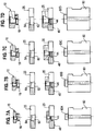
- the stepped hole is made, for example, by a boring process or by a two-stage pressing process.
- the perforation on the Blechstromschulter facing side has a diameter which corresponds at least substantially to the diameter of the shaft portion, wherein the shaft portion of the fastener is pressed through the perforation until the sheet metal bearing shoulder of the flange abuts the one side of the sheet metal part and the anti-rotation features or -nasen itself in the sheet metal part and the cylindrical rivet section is reshaped by means of a suitable die to a cone-shaped rivet bead which wedges in the cone-shaped diverging perforation.
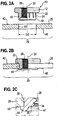
- a fastener 10 which has a flange portion 12 of larger diameter D1 and a shank portion 14 of smaller diameter D2 uf réelle, which extends away from the flange 12 and at its end facing away from the flange 12 end 16 merges into a cylindrical rivet portion 18 whose outer side 20 at least substantially is flush with the outside of the sheep part 14, that has the same diameter D2.
- the side of the flange part facing the shaft part 14 forms a sheet metal contact shoulder 22, and anti-rotation features 24 are provided on the shaft part 14.
- the anti-rotation features could also be provided on the sheet metal abutment shoulder (not shown) or arranged both on the sheet metal abutment shoulder 22 and on the shank part 14, for example with a rectangular shape or with a triangular shape in side view.
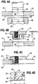
- the attachment to a relatively thin sheet metal part is now based on the Fig. 2A to 2C described.
- the sheet metal part 25 is at least in the region 26 of the attachment of the fastener before and after attachment of the fastener in a plane.
- the die on the intermediate plate of the press and the punch in the upper die the press or the stamp on the lower tool of the press and the die above the punch on the upper tool of the press or to attach to the intermediate plate of the press.
- the punch could be attached to the intermediate plate of the press and the die on the upper tool of the press.
- mount the die and the stamp in a so-called C-frame and make by appropriate hydraulic load of one or the other part, ie the die or the punch, the perforation of the sheet metal part.
- the corresponding tools can be designed as progressive dies, wherein in a first station, the perforation is made and in a second station, the fastener is guided into the previously produced perforation.
- the follow-on composite tool can also have other stations, so that further steps in the press are made simultaneously.
- Such an arrangement works by continuously moving the sheet metal part through the press, so that machining operations on the sheet metal strip in each work station of the press are carried out simultaneously with each stroke of the press. After leaving In the press or in the press, the individual sheet metal parts are then separated from each other or from the bleaching strip.
- the taper of the cone-diverging portion 62 of the hole in the sheet metal part can be selected by choosing the diameter D3 of the opening 68 of the die in comparison to the diameter D1 of the punch within the required limits. Preferably, one aims at an included cone angle of, for example, about 7 °.
- FIG. 7 shows then the same procedure with a thicker sheet metal part where the widened rivet flange 44 now significantly above the bottom plate 46 comes to an end, since just the sheet metal part 25 is here significantly thicker than the sheet metal part 25 of the FIGS. 6A to 6D ,
Landscapes
- Engineering & Computer Science (AREA)
- General Engineering & Computer Science (AREA)
- Mechanical Engineering (AREA)
- Connection Of Plates (AREA)
- Insertion Pins And Rivets (AREA)
- Iron Core Of Rotating Electric Machines (AREA)
Claims (14)
- Composant assemblé constitué par un élément de fixation (10) et par une pièce en tôle (25),
dans lequel
l'élément de fixation (10) présente une partie de bride (12) de grand diamètre (D1) et une partie de tige (14) de petit diamètre (D2) s'étendant en éloignement depuis la partie de bride (12) et se transformant, à son extrémité (16) détournée de la partie de bride (12), en une portion de rivetage cylindrique (18) dont la face extérieure est au moins sensiblement en affleurement avec la face extérieure de la partie de tige (14), c'est-à-dire qu'elle présente le même diamètre (D2),
la face de la partie de bride (12) tournée vers la partie de tige (14) constitue un épaulement d'appui de tôle (22), et
des caractéristiques de blocage anti-rotation (24) sont prévues sur la partie de tige (14) et/ou dans la zone de l'épaulement d'appui de tôle (22), caractérisé en ce que
l'élément de fixation est conçu pour l'utilisation avec des pièces en tôle (25) ayant des épaisseurs dans la plage de 3 mm et plus,
et en ce que
la pièce en tôle se situe dans un plan aussi bien directement au niveau du montage de l'élément de fixation qu'au voisinage de l'emplacement de montage dans des directions radiales, avant et après le montage de l'élément de fixation, eta) pour des pièces en tôle relativement minces ayant une épaisseur de 3 à 4,5 mm, la pièce en tôle (25) présente une ouverture cylindrique (40) percée lisse qui présente un diamètre (D2) qui correspond au moins sensiblement au diamètre (D2) de la partie de tige (14), la portion de rivetage cylindrique (18) étant mise en forme de serti de rivetage (44) qui prend appui contre la face (46) de la pièce en tôle (25) détournée de l'épaulement d'appui de tôle (22), oub) pour des pièces en tôle ayant une épaisseur moyenne, une épaisseur de 4,5 à 6,5 mm, la pièce en tôle (25) présente un trou étagé (50) ayant une partie de trou (52) cylindrique tournée vers l'épaulement d'appui de tôle (22) et ayant un petit diamètre (D2) qui correspond au moins sensiblement au diamètre (D2) de la partie de tige (14), et ayant une zone de trou (54) de grand diamètre qui reçoit la portion de rivetage (18) sertie en forme de serti de rivetage (44), ouc) pour des pièces en tôle relativement épaisses dans lesquelles la pièce en tôle (25) présente une épaisseur qui correspond au moins sensiblement à la longueur totale de la partie de tige (14) et de la portion de rivetage (18) ou bien qui est plus épaisse, la pièce en tôle (25) est pourvue d'un trou conique (62) qui diverge en direction depuis la face (42) de la pièce en tôle (25) tournée vers l'épaulement d'appui de tôle (22) jusqu'à la face (46) détournée de celui-ci, la portion de rivetage cylindrique (18) étant mise en forme de serti de rivetage conique (44) qui est calé dans le trou (62) divergeant en forme conique. - Composant assemblé selon la revendication 1,
caractérisé en ce que
l'élément de fixation (10) est un élément formant écrou. - Composant assemblé selon la revendication 1,
caractérisé en ce que
les caractéristiques de blocage anti-rotation (24) sont formées par des ergots de blocage anti-rotation qui forment des renfoncements (30) correspondants dans la pièce en tôle lors du montage de l'élément de fixation. - Composant assemblé selon la revendication 3,
caractérisé en ce que
les ergots de blocage anti-rotation (24) s'étendent en direction axiale (32) de la partie de tige (14) le long de celle-ci et/ou en directions radiales sur l'épaulement d'appui de tôle (22). - Composant assemblé selon l'une des revendications précédentes,
caractérisé en ce que
des pièces en tôle (25) plus épaisses présentent une épaisseur supérieure à 6,5 mm. - Composant assemblé selon l'une des revendications précédentes,
caractérisé en ce que
la partie de bride (12) est circulaire en section transversale radiale. - Composant assemblé selon l'une des revendications précédentes,
caractérisé en ce que
la partie de bride (12) présente une forme bombée, en vue latérale. - Composant assemblé selon l'une des revendications précédentes,
caractérisé en ce que
l'élément de fixation (10) présente une partie de tige creuse (14) pourvue d'un taraudage central (28) qui s'étend à travers la partie de bride (12) et à travers la partie de tige (14). - Procédé de réalisation d'un composant assemblé selon l'une des revendications précédentes avec une pièce en tôle (25) mince,
caractérisé en ce que
celle-ci est pré-perforée au moyen d'un poinçon de perforation afin de réaliser une ouverture cylindrique (40) percée lisse qui présente un diamètre (D2) qui correspond au moins sensiblement au diamètre (D2) de la partie de tige (14), la partie de tige (14) de l'élément de fixation (10) étant pressée à travers le trou cylindrique (40) jusqu'à ce que l'épaulement d'appui de tôle (22) de la partie de bride (12) vienne s'appuyer contre une face de la pièce en tôle (25) et que les caractéristiques ou ergots de blocage anti-rotation (24) se soient enfoncé(e)s dans la pièce en tôle (25) et que la portion de rivetage cylindrique (18) soit mise en forme de serti de rivetage (44) qui s'appuie contre la face (46) de la pièce en tôle (25) détournée de l'épaulement d'appui de tôle (22). - Procédé de réalisation d'un composant assemblé selon l'une des revendications 1 à 8 avec une pièce en tôle (25) d'épaisseur moyenne,
caractérisé en ce que
un trou étagé (50) est ménagé dans la pièce en tôle (25), présentant une partie de trou (52) cylindrique tournée vers l'épaulement d'appui de tôle (22) et ayant un petit diamètre (D2) qui correspond au moins sensiblement au diamètre (D2) de la partie de tige (14), et présentant une zone de trou (54) de grand diamètre,
la partie de tige (14) de l'élément de fixation (10) est pressée à travers le trou (50) jusqu'à ce que l'épaulement d'appui de tôle (22) de la partie de bride (12) vienne s'appuyer contre une face (42) de la pièce en tôle et que les caractéristiques ou ergots de blocage anti-rotation (24) se soient enfoncé(e)s dans la pièce en tôle (25) et
la portion de rivetage cylindrique (18) est mise en forme de serti de rivetage (44) qui est reçu dans la zone de trou (54) de grand diamètre. - Procédé selon la revendication 10,
caractérisé en ce que
le trou étagé (50) est réalisé par une opération de perçage ou par une opération de pressage à deux étages. - Procédé de réalisation d'un composant assemblé selon l'une des revendications 1 à 8 avec une pièce en tôle (25) relativement épaisse,
caractérisé en ce que
celle-ci est pré-perforée au moyen d'un poinçon de perforation (60) ou autre, afin de former un trou conique (62) qui diverge en direction de la face (42) de la pièce en tôle (25) tournée vers l'épaulement d'appui de tôle (22) jusqu'à la face (46) détournée de celui-ci, et
sur la face (64) tournée vers l'épaulement d'appui de tôle (22), le trou (62) présente un diamètre (D2) qui correspond au moins sensiblement au diamètre (D2) de la partie de tige (14),
la partie de tige (14) de l'élément de fixation (10) est pressée à travers le trou (62) jusqu'à ce que l'épaulement d'appui de tôle (22) de la partie de bride (12) vienne s'appuyer contre une face (42) de la pièce en tôle (25) et que les caractéristiques ou ergots de blocage anti-rotation (24) se soient enfoncé(e)s dans la pièce en tôle (25), et
la portion de rivetage cylindrique (18) est mise en forme de serti de rivetage (44) qui se cale dans le trou (62) divergeant en forme conique. - Procédé selon la revendication 12,
caractérisé en ce que
le trou (62) s'étendant en forme conique se raccorde à une zone cylindrique (64) du trou, qui est réalisée au voisinage de l'épaulement d'appui de tôle (22). - Procédé selon l'une des revendications 12 ou 13,
caractérisé en ce que
le trou conique (62) est réalisé en utilisant un poinçon de perforation (60) ayant un diamètre (D2) qui correspond au diamètre de la partie de tige (14), en combinaison avec une matrice de perforation (66) de grand diamètre (D3).
Applications Claiming Priority (1)
| Application Number | Priority Date | Filing Date | Title |
|---|---|---|---|
| DE102008052383A DE102008052383A1 (de) | 2008-10-20 | 2008-10-20 | Zusammenbauteil bestehend aus einem Befestigungselement und einem Blechteil sowie ein Verfahren zur Herstellung eines solchen Zusammenbauteils |
Publications (3)
| Publication Number | Publication Date |
|---|---|
| EP2177776A2 EP2177776A2 (fr) | 2010-04-21 |
| EP2177776A3 EP2177776A3 (fr) | 2015-05-27 |
| EP2177776B1 true EP2177776B1 (fr) | 2019-07-17 |
Family
ID=41563165
Family Applications (1)
| Application Number | Title | Priority Date | Filing Date |
|---|---|---|---|
| EP09013045.1A Active EP2177776B1 (fr) | 2008-10-20 | 2009-10-15 | Assemblage comprenant un élément de fixation et un élément en tôle et procédé de fabrication d'un tel élément d'ensemble |
Country Status (12)
| Country | Link |
|---|---|
| US (2) | US8221040B2 (fr) |
| EP (1) | EP2177776B1 (fr) |
| JP (1) | JP2010096351A (fr) |
| KR (1) | KR20100044120A (fr) |
| CN (1) | CN101725613B (fr) |
| BR (1) | BRPI0904822A2 (fr) |
| CA (1) | CA2683277C (fr) |
| DE (1) | DE102008052383A1 (fr) |
| ES (1) | ES2751172T3 (fr) |
| MX (1) | MX2009011128A (fr) |
| RU (1) | RU2512812C2 (fr) |
| TR (1) | TR201911053T4 (fr) |
Families Citing this family (38)
| Publication number | Priority date | Publication date | Assignee | Title |
|---|---|---|---|---|
| DE102004017866A1 (de) * | 2004-04-13 | 2005-11-03 | Profil-Verbindungstechnik Gmbh & Co. Kg | Verfahren zur Herstellung von Hohlkörperelementen, Hohlkörperelement, Zusammenbauteil sowie Folgeverbundwerkzeug zur Durchführung des Verfahrens |
| DE102008052383A1 (de) | 2008-10-20 | 2010-04-22 | Profil Verbindungstechnik Gmbh & Co. Kg | Zusammenbauteil bestehend aus einem Befestigungselement und einem Blechteil sowie ein Verfahren zur Herstellung eines solchen Zusammenbauteils |
| DE102009042336A1 (de) * | 2009-09-21 | 2011-03-24 | Profil Verbindungstechnik Gmbh & Co. Kg | Selbststanzendes hohles Einpresselement, Zusammenbauteil bestehend aus einem Einpresselement und einem Blechteil sowie ein Verfahren zur Herstellung einer selbststanzenden Einpressmutter sowie zur Anbringung einer selbststanzenden Einpressmutter |
| DE102010032866A1 (de) * | 2010-07-30 | 2012-02-02 | Profil Verbindungstechnik Gmbh & Co. Kg | Selbststanzendes Mutterelement und Zusammenbauteil bestehend aus dem Mutterelement und einem Blechteil |
| CN103118819B (zh) * | 2010-09-23 | 2016-03-30 | 舍弗勒技术股份两合公司 | 用铆钉连接变矩器中的板的方法及用于变矩器的组件 |
| CN102173029A (zh) * | 2010-12-29 | 2011-09-07 | 鸿富锦精密工业(深圳)有限公司 | 成型方法及用于该成型方法的螺母 |
| DE102012001088A1 (de) * | 2012-01-20 | 2013-07-25 | Profil Verbindungstechnik Gmbh & Co. Kg | Zweiteiliges Mutterelement für Kunststoffbauteile |
| DE102012001087A1 (de) * | 2012-01-20 | 2013-07-25 | Profil Verbindungstechnik Gmbh & Co. Kg | Kombination aus funktionselement und druckscheibe |
| DE102012003972A1 (de) | 2012-02-29 | 2013-08-29 | Profil Verbindungstechnik Gmbh & Co. Kg | Einstanzelement, Vormontagebauteil, Zusammenbauteil und Verfahren |
| JP6007018B2 (ja) * | 2012-07-31 | 2016-10-12 | 株式会社カネシン | ナット付羽子板ボルト |
| KR102131811B1 (ko) * | 2013-03-13 | 2020-07-08 | 엘지전자 주식회사 | 태양 전지 모듈 및 이를 포함하는 태양광 발전 장치 |
| KR101284244B1 (ko) * | 2013-03-19 | 2013-07-09 | 희성전자 주식회사 | 디스플레이 패널 고정용 너트 조립 방법 |
| US9435362B2 (en) | 2014-03-05 | 2016-09-06 | Morgan Truck Body, Llc | Bolt and nut assembly with plastic cover for controlled sealing compression |
| CN104842127A (zh) * | 2015-05-29 | 2015-08-19 | 东莞豪顺家具有限公司 | 一种背板用带底孔铆钉的快捷加工方法 |
| DE102016204619B4 (de) | 2016-03-21 | 2019-10-17 | Richard Bergner Verbindungstechnik Gmbh & Co. Kg | Einpressverbindung zwischen einem hochfesten Bauteil und einem Einpresselement, Verfahren zur Ausbildung einer solchen Einpressverbindung sowie Einpresselement für eine solche Einpressverbindung |
| CN106475737A (zh) * | 2016-09-29 | 2017-03-08 | 菲斯达排放控制装置(苏州)有限公司 | 执行器壳体与执行器底座的固定方法 |
| DE102016119479A1 (de) * | 2016-10-12 | 2018-04-12 | Profil Verbindungstechnik Gmbh & Co. Kg | Funktionselement zur fluiddichten Anbringung an ein Blechteil, Zusammenbauteil und Verfahren |
| WO2018193937A1 (fr) * | 2017-04-17 | 2018-10-25 | パナソニックIpマネジメント株式会社 | Écrou de rivet et son procédé de fabrication |
| CA3254953A1 (en) * | 2017-05-09 | 2025-04-24 | Penn Engineering & Manufacturing Corp. | Fastener and installation method for very thin sheets |
| FR3068541B1 (fr) * | 2017-06-28 | 2019-07-19 | Valeo Equipements Electriques Moteur | Assemblage de pieces et procede de fabrication d’un tel assemblage |
| JP6891081B2 (ja) * | 2017-09-20 | 2021-06-18 | プレス工業株式会社 | カシメナット、カシメナット用カシメ工具及びカシメナットの取付方法 |
| EP3734124B1 (fr) * | 2017-12-26 | 2023-12-06 | Asahi Yukizai Corporation | Mécanisme d'alignement de tuyau pour robinet à papillon |
| CN108436392B (zh) * | 2018-03-15 | 2019-07-09 | 江苏九众九自动化科技有限公司 | 缩颈模热镶硬质合金制作工艺 |
| WO2020084971A1 (fr) * | 2018-10-23 | 2020-04-30 | 株式会社神戸製鋼所 | Procédé de soudage à l'arc à des fins d'assemblage de matériaux multiples, élément d'aide à l'assemblage, joint soudé pour matériaux multiples, et matériau en plaque équipé d'un élément d'aide à l'assemblage |
| KR102701618B1 (ko) * | 2018-12-27 | 2024-09-03 | 삼성전자주식회사 | 스터드 |
| JP7301435B2 (ja) * | 2019-09-17 | 2023-07-03 | ガウリアン コーポレーション | 圧入ナット-ボルトアセンブリー |
| JP6850847B2 (ja) * | 2019-09-19 | 2021-03-31 | プレス工業株式会社 | カシメナットの取付工法及びカシメ工具 |
| CN111173826A (zh) * | 2020-02-25 | 2020-05-19 | 浙江邦利五金制品有限公司 | 一种螺母及其合金材料 |
| JP7332966B2 (ja) * | 2020-07-03 | 2023-08-24 | 日本製鉄株式会社 | 継手の製造方法、継手、及び自動車部品 |
| CN112192148A (zh) * | 2020-09-14 | 2021-01-08 | 苏州施必牢精密紧固件有限公司 | 预装盖形螺母的加工方法及其在高空塔筒的装配方法 |
| DE102021101366A1 (de) * | 2021-01-22 | 2022-07-28 | Profil Verbindungstechnik Gmbh & Co. Kg | Selbststanzendes Funktionselement, Zusammenbauteil und Verfahren zur Herstellung eines Zusammenbauteils |
| RU2769077C1 (ru) * | 2021-06-11 | 2022-03-28 | Компания Домидо Лимитед | Самоцентрирующийся вставной уплотнительный элемент |
| CN113369821B (zh) * | 2021-06-28 | 2022-09-27 | 中通钢构股份有限公司 | 余热回收通风管道用天圆地方施工工艺 |
| US12146519B2 (en) * | 2022-03-08 | 2024-11-19 | GM Global Technology Operations LLC | Fastening device with embedment |
| JP7473574B2 (ja) | 2022-03-18 | 2024-04-23 | 株式会社豊田中央研究所 | 締結用部材およびその製造方法 |
| CN116641954A (zh) * | 2023-05-23 | 2023-08-25 | 宾科汽车紧固件(昆山)有限公司 | 一种螺母连接机构与螺母 |
| DE102023208982A1 (de) * | 2023-09-15 | 2025-03-20 | Richard Bergner Holding GmbH & Co. KG | Einpresselement, Verfahren zur Ausbildung einer Einpressverbindung sowie Einpressverbindung |
| DE102023136189A1 (de) * | 2023-12-21 | 2025-06-26 | Arnold Umformtechnik Gmbh & Co. Kg | Verbindungselement, Anordnung und Verfahren |
Family Cites Families (38)
| Publication number | Priority date | Publication date | Assignee | Title |
|---|---|---|---|---|
| US2415695A (en) * | 1944-10-20 | 1947-02-11 | Cann Edward | Attaching nuts to plates |
| US3535678A (en) * | 1968-06-19 | 1970-10-20 | Deutsch Fastener Corp | Electrical terminal |
| US3938239A (en) * | 1973-05-14 | 1976-02-17 | Lauth Fasteners Limited | Method of forming a self-flanging nut joint |
| US4186787A (en) * | 1977-12-28 | 1980-02-05 | Amerace Corporation | Floating anchor nut assembly and basket member component |
| JPS5576210A (en) * | 1978-12-04 | 1980-06-09 | Sutaufu Corp | Fixing method of nut on supporting plate |
| US5564873A (en) * | 1980-02-02 | 1996-10-15 | Multifastener Corporation | Self-attaching fastening element and method of attachment |
| JPS6052410U (ja) * | 1983-09-19 | 1985-04-12 | 西精工株式会社 | カ−リングナツト |
| JPH0328514A (ja) * | 1989-04-27 | 1991-02-06 | Iwata Booruto Kogyo Kk | クリンチナット及びその取付方法 |
| JPH04237536A (ja) * | 1991-01-17 | 1992-08-26 | Press Kogyo Kk | リベット締結方法 |
| US5528812A (en) | 1991-10-31 | 1996-06-25 | Profil-Verbindungstechnik Gmbh & Co. Kg | Method of attaching a fastener to a plurality of panels |
| US5251370A (en) | 1991-10-31 | 1993-10-12 | Profil Verbindungstechnik Gmbh & Co. | Method of attaching a fastening element to a panel |
| US5267832A (en) * | 1992-03-30 | 1993-12-07 | United Technologies Corporation | Flarable retainer |
| US5445483A (en) * | 1993-08-23 | 1995-08-29 | Emhart Inc. | Female clinch fastener with cold-formed locking flange and associated installation method |
| JPH07208439A (ja) * | 1994-01-28 | 1995-08-11 | Watanabe Seisakusho:Kk | 全自動座金付きナットの同時加工組立装置 |
| US6125524A (en) * | 1994-03-25 | 2000-10-03 | Multifastener Corporation | Rivetable element, assembly, method of assembly and riveting die |
| DE29522323U1 (de) * | 1994-11-22 | 2001-09-06 | Profil Verbindungstechnik GmbH & Co. KG, 61381 Friedrichsdorf | Befestigungselement |
| ES2183895T5 (es) | 1995-06-07 | 2007-03-01 | PROFIL-VERBINDUNGSTECHNIK GMBH & CO. KG | Dispositivo de guia y/o recalcado para elementos, especialmente elementos a soldar. |
| US5611654A (en) * | 1995-08-02 | 1997-03-18 | Southco, Inc. | Captive nut |
| JP3293026B2 (ja) * | 1996-09-30 | 2002-06-17 | 株式会社サンノハシ | 嵌合部を有する部材とその製造方法及び取付方法 |
| RU2164630C1 (ru) * | 2000-05-06 | 2001-03-27 | Открытое акционерное общество "Нормаль" | Самоконтрящаяся анкерная гайка из титановых сплавов |
| US6318940B1 (en) * | 2000-06-21 | 2001-11-20 | Illinois Tool Works Inc. | Fastener for self-locking securement within a panel opening |
| US7124492B2 (en) * | 2001-07-19 | 2006-10-24 | Whitesell International Corporation | Fastener, method of attaching a fastener to a panel and fastener and panel assembly |
| US6543855B2 (en) * | 2001-08-24 | 2003-04-08 | Bae Industries, Inc. | Cup style spacer for attaching an upper arm to a seat frame forming a part of a seat integrated restraint mechanism |
| DE102004031379A1 (de) * | 2003-07-25 | 2005-02-10 | Profil Verbindungstechnik Gmbh & Co. Kg | Verfahren zur Anbringung eines Funktionselementes an ein Bleichteil sowie Zusammenbauteil |
| JP2005106183A (ja) * | 2003-09-30 | 2005-04-21 | Anritsu Corp | 締結支持具 |
| ATE474901T1 (de) | 2003-11-06 | 2010-08-15 | Nemoto Tokushu Kagaku Kk | Phosphoreszierender leuchtstoff und herstellungsverfahren dafür |
| DE102004020676A1 (de) * | 2004-04-28 | 2005-11-24 | Profil-Verbindungstechnik Gmbh & Co. Kg | Verfahren und Vorrichtung zur Anbringung eines Befestigungselements an ein Bauteil, insbesondere an ein Blechteil |
| DE102004043688A1 (de) * | 2004-06-23 | 2006-04-06 | Profil-Verbindungstechnik Gmbh & Co. Kg | Verfahren zur Herstellung eines Zusammenbauteils bestehend aus einem Blechteil und einem an diesem angebrachten Funktionselement, Blechteil sowie Funktionselement |
| DE102004042478B4 (de) * | 2004-09-02 | 2008-05-29 | Richard Bergner Verbindungstechnik Gmbh & Co. Kg | Verfahren zur verdrehsicheren Befestigung eines Funktionselements in einem Bauteil sowie Verbindung zwischen einem Bauteil und einem Funktionselement |
| DE102004062391A1 (de) * | 2004-12-23 | 2006-07-13 | Profil-Verbindungstechnik Gmbh & Co. Kg | Ein durch Nieten an ein Blechteil anbringbares Element sowie Zusammenbauteil und Verfahren zur Erzeugung des Zusammenbauteils |
| DE202005005536U1 (de) * | 2005-04-07 | 2005-06-09 | Böllhoff Verbindungstechnik GmbH | Blindniet |
| US7480971B2 (en) * | 2005-04-28 | 2009-01-27 | Profile Verbindungstechnik Gmbh & Co., Kg | Method and device for mounting a fastener element on a part, particularly a sheet metal part |
| JP3121114U (ja) * | 2006-02-03 | 2006-04-27 | 大阪製鐵株式会社 | ナットが固着された鋼材 |
| US7740436B2 (en) | 2006-03-22 | 2010-06-22 | R B & W Manufacturing Llc | Clinch nut |
| CN101086270B (zh) * | 2006-06-05 | 2012-11-21 | 形状连接技术有限公司及两合公司 | 可通过铆接连接到金属薄板部件上的元件和一种零件总成 |
| DE102007034987A1 (de) | 2007-07-26 | 2009-01-29 | Profil Verbindungstechnik Gmbh & Co. Kg | Einpresselement zum Einpressen in ein nicht gelochtes oder gelochtes Bauteil sowie Verfahren zur Herstellung des Einpresselements |
| DE102008052383A1 (de) | 2008-10-20 | 2010-04-22 | Profil Verbindungstechnik Gmbh & Co. Kg | Zusammenbauteil bestehend aus einem Befestigungselement und einem Blechteil sowie ein Verfahren zur Herstellung eines solchen Zusammenbauteils |
| DE102010047636A1 (de) * | 2010-10-06 | 2012-04-12 | Profil Verbindungstechnik Gmbh & Co. Kg | Funktionselement zur Anbringung an einem Kunststoffbauteil, ein Zusammenbauteil, eine Matrize und Verfahren |
-
2008
- 2008-10-20 DE DE102008052383A patent/DE102008052383A1/de not_active Ceased
-
2009
- 2009-10-15 TR TR2019/11053T patent/TR201911053T4/tr unknown
- 2009-10-15 ES ES09013045T patent/ES2751172T3/es active Active
- 2009-10-15 EP EP09013045.1A patent/EP2177776B1/fr active Active
- 2009-10-15 MX MX2009011128A patent/MX2009011128A/es active IP Right Grant
- 2009-10-16 BR BRPI0904822-7A patent/BRPI0904822A2/pt not_active IP Right Cessation
- 2009-10-16 JP JP2009238814A patent/JP2010096351A/ja active Pending
- 2009-10-19 RU RU2009138603/12A patent/RU2512812C2/ru not_active IP Right Cessation
- 2009-10-19 US US12/581,800 patent/US8221040B2/en active Active
- 2009-10-20 KR KR1020090099692A patent/KR20100044120A/ko not_active Ceased
- 2009-10-20 CA CA2683277A patent/CA2683277C/fr not_active Expired - Fee Related
- 2009-10-20 CN CN200910175175.5A patent/CN101725613B/zh active Active
-
2012
- 2012-05-03 US US13/462,903 patent/US8646166B2/en active Active
Non-Patent Citations (1)
| Title |
|---|
| None * |
Also Published As
| Publication number | Publication date |
|---|---|
| KR20100044120A (ko) | 2010-04-29 |
| US8221040B2 (en) | 2012-07-17 |
| CA2683277A1 (fr) | 2010-04-20 |
| US8646166B2 (en) | 2014-02-11 |
| JP2010096351A (ja) | 2010-04-30 |
| CA2683277C (fr) | 2017-03-28 |
| CN101725613A (zh) | 2010-06-09 |
| RU2009138603A (ru) | 2011-04-27 |
| BRPI0904822A2 (pt) | 2011-03-15 |
| CN101725613B (zh) | 2014-05-07 |
| MX2009011128A (es) | 2010-05-14 |
| TR201911053T4 (tr) | 2019-08-21 |
| US20120216390A1 (en) | 2012-08-30 |
| RU2512812C2 (ru) | 2014-04-10 |
| ES2751172T3 (es) | 2020-03-30 |
| US20100129173A1 (en) | 2010-05-27 |
| EP2177776A2 (fr) | 2010-04-21 |
| EP2177776A3 (fr) | 2015-05-27 |
| DE102008052383A1 (de) | 2010-04-22 |
Similar Documents
| Publication | Publication Date | Title |
|---|---|---|
| EP2177776B1 (fr) | Assemblage comprenant un élément de fixation et un élément en tôle et procédé de fabrication d'un tel élément d'ensemble | |
| EP2980426B1 (fr) | Composant d'assemblage comprenant un element a sertir et une partie de tole | |
| EP1806509B1 (fr) | Élément fonctionnel, ensemble de montage composés de l'élément fonctionnel et d'une plaque ainsi que d'une procédure de attacher d'un élément fonctionnel | |
| EP2292940B1 (fr) | Elément d'écrou auto-perforant et composant constitué de l'élément d'écrou et d'un élément de tôle | |
| EP1269033B1 (fr) | Ensemble element fonctionnel, element fonctionnel, element d'assemblage auxiliaire, piece assemblee et procedes pour obtenir une piece assemblee | |
| EP2549128B1 (fr) | Elément fonctionnel avec propriétés de sécurisation contre la torsion et composant composé d'un élément fonctionnel et d'une partie en tôle | |
| EP2032282B1 (fr) | Rivet auto-poinçonneur et matrice | |
| EP2412991B1 (fr) | Elément d'écrou auto-perforant et composant constitué de l'élément d'écrou et d'un élément de tôle | |
| EP1690013B1 (fr) | Element fonctionnel, composant d'assemblage compose de l'element fonctionnel combine a une tole, procede de fabrication du composant d'assemblage et procede de fabrication de l'element fonctionnel | |
| EP3216556B1 (fr) | Procédé de fixation d'un élément fonctionnel sur une pièce de tôlerie | |
| DE10243759B4 (de) | Verfahren zur Erzeugung einer elektrisch leitenden Verbindung zwischen einer elektrischen Anschlusseinrichtung wie ein Kabelschuh und einem Blechteil, Befestigungselement und Zusammenbauteil | |
| WO1999049227A2 (fr) | Procede, outil et poinçon pour relier des composants a une plaque | |
| DE102013217640A1 (de) | Verfahren zur Anbringung eines Befestigungselements an ein Werkstück, Kombination einer Scheibe mit einer Matrize sowie Matrize | |
| EP1442809B1 (fr) | Procédé de production d'éléments à corps creux | |
| WO2017157959A1 (fr) | Elément d'insertion à force autoperforant, assemblage par insertion à force et procédé pour réaliser un tel assemblage par insertion à force | |
| EP0759510B1 (fr) | Corps creux, matrice pour le corps creux, méthode pour la fixation d'un corps creux sur un élément en forme plate et ensemble de montage | |
| DE102013218548A1 (de) | Lochstempel sowie Verfahren zum Durchstanzen eines Werkstücks, das als Schaummaterial und/oder als Sandwichmaterial vorliegt, sowie Verfahren zur Herstellung des Lochstempels | |
| EP1370777B1 (fr) | Element fonctionnel, piece d'assemblage comprenant une piece de tole et un element fonctionnel, et procede permettant la fixation d'un element fonctionnel a une piece de tole | |
| DE102006062073A1 (de) | Funktionselement, Zusammenbauteil bestehend aus dem Funktionselement und einem Blechteil sowie Verfahren zum Anbringen eines Funktionselements | |
| EP1892427B1 (fr) | Élément de fixation et procédure de fixation de cet élément de fixation à un élément de tôle metallique | |
| EP3564545B1 (fr) | Composant d'assemblage comprenant un composant et d'un élément doté d'une partie de tête et d'un col disposé sur un côté de la partie de tête ainsi que son procédé de fabrication | |
| DE202006013981U1 (de) | Stanzniet und Matrize | |
| EP2145116B1 (fr) | Procédé pour fixer un élément d'assemblage ou fonctionnel sur un matériau plat, assemblage riveté et élément d'assemblage ou fonctionnel | |
| DE102019110635A1 (de) | Zusammenbauteil bestehend aus einem Bauteil und einem Element mit einem Kopfteil und einem auf einer Seite des Kopfteils angeordneten Kragen sowie Herstellungsverfahren | |
| EP2042751B1 (fr) | Procédé d'application d'un élément de fonction sur une pièce en tôle et composant d'ensemble |
Legal Events
| Date | Code | Title | Description |
|---|---|---|---|
| PUAI | Public reference made under article 153(3) epc to a published international application that has entered the european phase |
Free format text: ORIGINAL CODE: 0009012 |
|
| AK | Designated contracting states |
Kind code of ref document: A2 Designated state(s): AT BE BG CH CY CZ DE DK EE ES FI FR GB GR HR HU IE IS IT LI LT LU LV MC MK MT NL NO PL PT RO SE SI SK SM TR |
|
| AX | Request for extension of the european patent |
Extension state: AL BA RS |
|
| PUAL | Search report despatched |
Free format text: ORIGINAL CODE: 0009013 |
|
| AK | Designated contracting states |
Kind code of ref document: A3 Designated state(s): AT BE BG CH CY CZ DE DK EE ES FI FR GB GR HR HU IE IS IT LI LT LU LV MC MK MT NL NO PL PT RO SE SI SK SM TR |
|
| AX | Request for extension of the european patent |
Extension state: AL BA RS |
|
| RIC1 | Information provided on ipc code assigned before grant |
Ipc: F16B 37/06 20060101AFI20150422BHEP |
|
| 17P | Request for examination filed |
Effective date: 20150923 |
|
| RBV | Designated contracting states (corrected) |
Designated state(s): AT BE BG CH CY CZ DE DK EE ES FI FR GB GR HR HU IE IS IT LI LT LU LV MC MK MT NL NO PL PT RO SE SI SK SM TR |
|
| STAA | Information on the status of an ep patent application or granted ep patent |
Free format text: STATUS: EXAMINATION IS IN PROGRESS |
|
| 17Q | First examination report despatched |
Effective date: 20180111 |
|
| GRAP | Despatch of communication of intention to grant a patent |
Free format text: ORIGINAL CODE: EPIDOSNIGR1 |
|
| STAA | Information on the status of an ep patent application or granted ep patent |
Free format text: STATUS: GRANT OF PATENT IS INTENDED |
|
| INTG | Intention to grant announced |
Effective date: 20190131 |
|
| GRAS | Grant fee paid |
Free format text: ORIGINAL CODE: EPIDOSNIGR3 |
|
| GRAA | (expected) grant |
Free format text: ORIGINAL CODE: 0009210 |
|
| STAA | Information on the status of an ep patent application or granted ep patent |
Free format text: STATUS: THE PATENT HAS BEEN GRANTED |
|
| AK | Designated contracting states |
Kind code of ref document: B1 Designated state(s): AT BE BG CH CY CZ DE DK EE ES FI FR GB GR HR HU IE IS IT LI LT LU LV MC MK MT NL NO PL PT RO SE SI SK SM TR |
|
| REG | Reference to a national code |
Ref country code: GB Ref legal event code: FG4D Free format text: NOT ENGLISH |
|
| REG | Reference to a national code |
Ref country code: CH Ref legal event code: EP |
|
| REG | Reference to a national code |
Ref country code: IE Ref legal event code: FG4D Free format text: LANGUAGE OF EP DOCUMENT: GERMAN |
|
| REG | Reference to a national code |
Ref country code: DE Ref legal event code: R096 Ref document number: 502009015874 Country of ref document: DE |
|
| REG | Reference to a national code |
Ref country code: AT Ref legal event code: REF Ref document number: 1156108 Country of ref document: AT Kind code of ref document: T Effective date: 20190815 |
|
| REG | Reference to a national code |
Ref country code: NL Ref legal event code: MP Effective date: 20190717 |
|
| REG | Reference to a national code |
Ref country code: LT Ref legal event code: MG4D |
|
| PG25 | Lapsed in a contracting state [announced via postgrant information from national office to epo] |
Ref country code: SE Free format text: LAPSE BECAUSE OF FAILURE TO SUBMIT A TRANSLATION OF THE DESCRIPTION OR TO PAY THE FEE WITHIN THE PRESCRIBED TIME-LIMIT Effective date: 20190717 Ref country code: NO Free format text: LAPSE BECAUSE OF FAILURE TO SUBMIT A TRANSLATION OF THE DESCRIPTION OR TO PAY THE FEE WITHIN THE PRESCRIBED TIME-LIMIT Effective date: 20191017 Ref country code: FI Free format text: LAPSE BECAUSE OF FAILURE TO SUBMIT A TRANSLATION OF THE DESCRIPTION OR TO PAY THE FEE WITHIN THE PRESCRIBED TIME-LIMIT Effective date: 20190717 Ref country code: PT Free format text: LAPSE BECAUSE OF FAILURE TO SUBMIT A TRANSLATION OF THE DESCRIPTION OR TO PAY THE FEE WITHIN THE PRESCRIBED TIME-LIMIT Effective date: 20191118 Ref country code: HR Free format text: LAPSE BECAUSE OF FAILURE TO SUBMIT A TRANSLATION OF THE DESCRIPTION OR TO PAY THE FEE WITHIN THE PRESCRIBED TIME-LIMIT Effective date: 20190717 Ref country code: BG Free format text: LAPSE BECAUSE OF FAILURE TO SUBMIT A TRANSLATION OF THE DESCRIPTION OR TO PAY THE FEE WITHIN THE PRESCRIBED TIME-LIMIT Effective date: 20191017 Ref country code: NL Free format text: LAPSE BECAUSE OF FAILURE TO SUBMIT A TRANSLATION OF THE DESCRIPTION OR TO PAY THE FEE WITHIN THE PRESCRIBED TIME-LIMIT Effective date: 20190717 Ref country code: LT Free format text: LAPSE BECAUSE OF FAILURE TO SUBMIT A TRANSLATION OF THE DESCRIPTION OR TO PAY THE FEE WITHIN THE PRESCRIBED TIME-LIMIT Effective date: 20190717 |
|
| PG25 | Lapsed in a contracting state [announced via postgrant information from national office to epo] |
Ref country code: GR Free format text: LAPSE BECAUSE OF FAILURE TO SUBMIT A TRANSLATION OF THE DESCRIPTION OR TO PAY THE FEE WITHIN THE PRESCRIBED TIME-LIMIT Effective date: 20191018 Ref country code: LV Free format text: LAPSE BECAUSE OF FAILURE TO SUBMIT A TRANSLATION OF THE DESCRIPTION OR TO PAY THE FEE WITHIN THE PRESCRIBED TIME-LIMIT Effective date: 20190717 Ref country code: IS Free format text: LAPSE BECAUSE OF FAILURE TO SUBMIT A TRANSLATION OF THE DESCRIPTION OR TO PAY THE FEE WITHIN THE PRESCRIBED TIME-LIMIT Effective date: 20191117 |
|
| REG | Reference to a national code |
Ref country code: ES Ref legal event code: FG2A Ref document number: 2751172 Country of ref document: ES Kind code of ref document: T3 Effective date: 20200330 |
|
| PG25 | Lapsed in a contracting state [announced via postgrant information from national office to epo] |
Ref country code: RO Free format text: LAPSE BECAUSE OF FAILURE TO SUBMIT A TRANSLATION OF THE DESCRIPTION OR TO PAY THE FEE WITHIN THE PRESCRIBED TIME-LIMIT Effective date: 20190717 Ref country code: DK Free format text: LAPSE BECAUSE OF FAILURE TO SUBMIT A TRANSLATION OF THE DESCRIPTION OR TO PAY THE FEE WITHIN THE PRESCRIBED TIME-LIMIT Effective date: 20190717 Ref country code: PL Free format text: LAPSE BECAUSE OF FAILURE TO SUBMIT A TRANSLATION OF THE DESCRIPTION OR TO PAY THE FEE WITHIN THE PRESCRIBED TIME-LIMIT Effective date: 20190717 Ref country code: EE Free format text: LAPSE BECAUSE OF FAILURE TO SUBMIT A TRANSLATION OF THE DESCRIPTION OR TO PAY THE FEE WITHIN THE PRESCRIBED TIME-LIMIT Effective date: 20190717 |
|
| PG25 | Lapsed in a contracting state [announced via postgrant information from national office to epo] |
Ref country code: CZ Free format text: LAPSE BECAUSE OF FAILURE TO SUBMIT A TRANSLATION OF THE DESCRIPTION OR TO PAY THE FEE WITHIN THE PRESCRIBED TIME-LIMIT Effective date: 20190717 Ref country code: SM Free format text: LAPSE BECAUSE OF FAILURE TO SUBMIT A TRANSLATION OF THE DESCRIPTION OR TO PAY THE FEE WITHIN THE PRESCRIBED TIME-LIMIT Effective date: 20190717 Ref country code: IS Free format text: LAPSE BECAUSE OF FAILURE TO SUBMIT A TRANSLATION OF THE DESCRIPTION OR TO PAY THE FEE WITHIN THE PRESCRIBED TIME-LIMIT Effective date: 20200224 Ref country code: MC Free format text: LAPSE BECAUSE OF FAILURE TO SUBMIT A TRANSLATION OF THE DESCRIPTION OR TO PAY THE FEE WITHIN THE PRESCRIBED TIME-LIMIT Effective date: 20190717 Ref country code: SK Free format text: LAPSE BECAUSE OF FAILURE TO SUBMIT A TRANSLATION OF THE DESCRIPTION OR TO PAY THE FEE WITHIN THE PRESCRIBED TIME-LIMIT Effective date: 20190717 |
|
| REG | Reference to a national code |
Ref country code: CH Ref legal event code: PL |
|
| REG | Reference to a national code |
Ref country code: DE Ref legal event code: R097 Ref document number: 502009015874 Country of ref document: DE |
|
| PLBE | No opposition filed within time limit |
Free format text: ORIGINAL CODE: 0009261 |
|
| STAA | Information on the status of an ep patent application or granted ep patent |
Free format text: STATUS: NO OPPOSITION FILED WITHIN TIME LIMIT |
|
| PG2D | Information on lapse in contracting state deleted |
Ref country code: IS |
|
| PG25 | Lapsed in a contracting state [announced via postgrant information from national office to epo] |
Ref country code: LU Free format text: LAPSE BECAUSE OF NON-PAYMENT OF DUE FEES Effective date: 20191015 Ref country code: CH Free format text: LAPSE BECAUSE OF NON-PAYMENT OF DUE FEES Effective date: 20191031 Ref country code: LI Free format text: LAPSE BECAUSE OF NON-PAYMENT OF DUE FEES Effective date: 20191031 |
|
| 26N | No opposition filed |
Effective date: 20200603 |
|
| REG | Reference to a national code |
Ref country code: BE Ref legal event code: MM Effective date: 20191031 |
|
| PG25 | Lapsed in a contracting state [announced via postgrant information from national office to epo] |
Ref country code: BE Free format text: LAPSE BECAUSE OF NON-PAYMENT OF DUE FEES Effective date: 20191031 Ref country code: SI Free format text: LAPSE BECAUSE OF FAILURE TO SUBMIT A TRANSLATION OF THE DESCRIPTION OR TO PAY THE FEE WITHIN THE PRESCRIBED TIME-LIMIT Effective date: 20190717 |
|
| PG25 | Lapsed in a contracting state [announced via postgrant information from national office to epo] |
Ref country code: IE Free format text: LAPSE BECAUSE OF NON-PAYMENT OF DUE FEES Effective date: 20191015 |
|
| REG | Reference to a national code |
Ref country code: AT Ref legal event code: MM01 Ref document number: 1156108 Country of ref document: AT Kind code of ref document: T Effective date: 20191015 |
|
| PG25 | Lapsed in a contracting state [announced via postgrant information from national office to epo] |
Ref country code: AT Free format text: LAPSE BECAUSE OF NON-PAYMENT OF DUE FEES Effective date: 20191015 |
|
| PG25 | Lapsed in a contracting state [announced via postgrant information from national office to epo] |
Ref country code: CY Free format text: LAPSE BECAUSE OF FAILURE TO SUBMIT A TRANSLATION OF THE DESCRIPTION OR TO PAY THE FEE WITHIN THE PRESCRIBED TIME-LIMIT Effective date: 20190717 |
|
| PG25 | Lapsed in a contracting state [announced via postgrant information from national office to epo] |
Ref country code: MT Free format text: LAPSE BECAUSE OF FAILURE TO SUBMIT A TRANSLATION OF THE DESCRIPTION OR TO PAY THE FEE WITHIN THE PRESCRIBED TIME-LIMIT Effective date: 20190717 Ref country code: HU Free format text: LAPSE BECAUSE OF FAILURE TO SUBMIT A TRANSLATION OF THE DESCRIPTION OR TO PAY THE FEE WITHIN THE PRESCRIBED TIME-LIMIT; INVALID AB INITIO Effective date: 20091015 |
|
| PG25 | Lapsed in a contracting state [announced via postgrant information from national office to epo] |
Ref country code: MK Free format text: LAPSE BECAUSE OF FAILURE TO SUBMIT A TRANSLATION OF THE DESCRIPTION OR TO PAY THE FEE WITHIN THE PRESCRIBED TIME-LIMIT Effective date: 20190717 |
|
| PGFP | Annual fee paid to national office [announced via postgrant information from national office to epo] |
Ref country code: IT Payment date: 20250922 Year of fee payment: 17 |
|
| PGFP | Annual fee paid to national office [announced via postgrant information from national office to epo] |
Ref country code: GB Payment date: 20250821 Year of fee payment: 17 |
|
| PGFP | Annual fee paid to national office [announced via postgrant information from national office to epo] |
Ref country code: FR Payment date: 20250821 Year of fee payment: 17 |
|
| PGFP | Annual fee paid to national office [announced via postgrant information from national office to epo] |
Ref country code: DE Payment date: 20250819 Year of fee payment: 17 |
|
| PGFP | Annual fee paid to national office [announced via postgrant information from national office to epo] |
Ref country code: TR Payment date: 20251009 Year of fee payment: 17 |
|
| PGFP | Annual fee paid to national office [announced via postgrant information from national office to epo] |
Ref country code: ES Payment date: 20251107 Year of fee payment: 17 |