EP2177957A2 - Analoger Anzeiger aus kristallenem Material, Uhr mit solchem Anzeiger, und Herstellungsverfahren dafür - Google Patents
Analoger Anzeiger aus kristallenem Material, Uhr mit solchem Anzeiger, und Herstellungsverfahren dafür Download PDFInfo
- Publication number
- EP2177957A2 EP2177957A2 EP10152831A EP10152831A EP2177957A2 EP 2177957 A2 EP2177957 A2 EP 2177957A2 EP 10152831 A EP10152831 A EP 10152831A EP 10152831 A EP10152831 A EP 10152831A EP 2177957 A2 EP2177957 A2 EP 2177957A2
- Authority
- EP
- European Patent Office
- Prior art keywords
- main body
- needle
- display member
- silicon
- analog display
- Prior art date
- Legal status (The legal status is an assumption and is not a legal conclusion. Google has not performed a legal analysis and makes no representation as to the accuracy of the status listed.)
- Granted
Links
Images
Classifications
-
- B—PERFORMING OPERATIONS; TRANSPORTING
- B81—MICROSTRUCTURAL TECHNOLOGY
- B81C—PROCESSES OR APPARATUS SPECIALLY ADAPTED FOR THE MANUFACTURE OR TREATMENT OF MICROSTRUCTURAL DEVICES OR SYSTEMS
- B81C99/00—Subject matter not provided for in other groups of this subclass
- B81C99/0075—Manufacture of substrate-free structures
- B81C99/008—Manufacture of substrate-free structures separating the processed structure from a mother substrate
-
- G—PHYSICS
- G04—HOROLOGY
- G04B—MECHANICALLY-DRIVEN CLOCKS OR WATCHES; MECHANICAL PARTS OF CLOCKS OR WATCHES IN GENERAL; TIME PIECES USING THE POSITION OF THE SUN, MOON OR STARS
- G04B19/00—Indicating the time by visual means
- G04B19/04—Hands; Discs with a single mark or the like
-
- G—PHYSICS
- G04—HOROLOGY
- G04B—MECHANICALLY-DRIVEN CLOCKS OR WATCHES; MECHANICAL PARTS OF CLOCKS OR WATCHES IN GENERAL; TIME PIECES USING THE POSITION OF THE SUN, MOON OR STARS
- G04B19/00—Indicating the time by visual means
- G04B19/04—Hands; Discs with a single mark or the like
- G04B19/042—Construction and manufacture of the hands; arrangements for increasing reading accuracy
-
- G—PHYSICS
- G04—HOROLOGY
- G04B—MECHANICALLY-DRIVEN CLOCKS OR WATCHES; MECHANICAL PARTS OF CLOCKS OR WATCHES IN GENERAL; TIME PIECES USING THE POSITION OF THE SUN, MOON OR STARS
- G04B45/00—Time pieces of which the indicating means or cases provoke special effects, e.g. aesthetic effects
- G04B45/02—Time pieces of which the clockwork is visible partly or wholly
-
- G—PHYSICS
- G04—HOROLOGY
- G04D—APPARATUS OR TOOLS SPECIALLY DESIGNED FOR MAKING OR MAINTAINING CLOCKS OR WATCHES
- G04D3/00—Watchmakers' or watch-repairers' machines or tools for working materials
-
- G—PHYSICS
- G04—HOROLOGY
- G04D—APPARATUS OR TOOLS SPECIALLY DESIGNED FOR MAKING OR MAINTAINING CLOCKS OR WATCHES
- G04D3/00—Watchmakers' or watch-repairers' machines or tools for working materials
- G04D3/0002—Watchmakers' or watch-repairers' machines or tools for working materials for mechanical working other than with a lathe
- G04D3/0043—Watchmakers' or watch-repairers' machines or tools for working materials for mechanical working other than with a lathe for components of the time-indicating mechanisms
- G04D3/0046—Watchmakers' or watch-repairers' machines or tools for working materials for mechanical working other than with a lathe for components of the time-indicating mechanisms for hands
-
- G—PHYSICS
- G04—HOROLOGY
- G04D—APPARATUS OR TOOLS SPECIALLY DESIGNED FOR MAKING OR MAINTAINING CLOCKS OR WATCHES
- G04D3/00—Watchmakers' or watch-repairers' machines or tools for working materials
- G04D3/0069—Watchmakers' or watch-repairers' machines or tools for working materials for working with non-mechanical means, e.g. chemical, electrochemical, metallising, vapourising; with electron beams, laser beams
-
- Y—GENERAL TAGGING OF NEW TECHNOLOGICAL DEVELOPMENTS; GENERAL TAGGING OF CROSS-SECTIONAL TECHNOLOGIES SPANNING OVER SEVERAL SECTIONS OF THE IPC; TECHNICAL SUBJECTS COVERED BY FORMER USPC CROSS-REFERENCE ART COLLECTIONS [XRACs] AND DIGESTS
- Y10—TECHNICAL SUBJECTS COVERED BY FORMER USPC
- Y10T—TECHNICAL SUBJECTS COVERED BY FORMER US CLASSIFICATION
- Y10T74/00—Machine element or mechanism
- Y10T74/15—Intermittent grip type mechanical movement
- Y10T74/1558—Grip units and features
- Y10T74/1587—Grip features
Definitions
- the invention relates to an analog display member such as a timepiece needle.
- the invention also relates to a timepiece and a method of manufacturing a display member.
- the manufacture of a needle intended to be used as a display member in a timepiece is particularly complex, especially when it is a needle intended to equip a high-end timepiece, for which the needle must have a particularly neat surface appearance, possibly with facets.
- the needles are made of brass, steel, gold, aluminum, or special alloy. They can be galvanically treated, coated with paint, oxidized, or rough when the material used is gold. They are generally made by machining or stamping.
- the present invention aims to provide a needle which is easier to manufacture while offering great freedom of design of its shape, and which can be manufactured in series so as to minimize production costs.
- the invention proposes an analog display element equipping a timepiece, of the type comprising a main body in which is arranged a pinhole, the pinhole being fitted on a drive shaft , characterized in that the main body is made of crystalline material based on silicon.
- the main body of the analog display member is in the form of a watchmaker's needle.
- the display member according to the invention has the advantage of being easily manufactured using technologies proven in microelectronics. for the manufacture of integrated circuits and in micromechanics for the manufacture of micro-structures.
- Silicon has the advantage of being very light, since its density is about 2.49 kg / dm3, which makes it possible to minimize the mass of the display member, therefore the problems of inertia and unbalanced, especially when it is shaped like a needle.
- the reduction of the unbalance and the inertia of the display member has a favorable influence on the dimensioning of the drive means of the display member and on the energy consumption of these drive means.
- the invention also proposes a timepiece characterized in that it comprises at least one analog display element according to one of the preceding characteristics.
- the invention also proposes a method of manufacturing analog display members intended to equip timepieces, each analog display member comprising a main body in which is arranged an axis hole, the axis hole. being fitted on a drive shaft, characterized in that it comprises at least one micromachining step of a silicon-based crystalline material plate so as to produce at least one main body made of such a crystalline material with its axis hole.
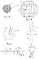
- the analog display members 10 are here needles 10, an example of which is shown schematically on the figure 9 .
- each needle 10 comprises a main body 11 which is made of crystalline material based on silicon.
- Silicon-based crystalline material is here understood to mean a crystalline material containing silicon such as monocrystalline silicon, polycrystalline silicon, and quartz.
- the needle 10 according to the invention is micro-machined in a monocrystalline silicon plate 12 such as those used for the production of integrated electronic circuits, these plates being generally designated by the term "wafer”.
- a series of several needles 10 is made in the same silicon wafer 12, according to a method called "batch processing", using technologies from the field of microelectronics that make it possible to manufacture mechanical microstructures in a plate of silicon 12.
- These methods generally use masking techniques which make it possible to locally eliminate a layer of material of a predetermined thickness.
- Dry etching methods use, for example, a laser beam or a high density plasma source.
- Electropolishing is an example of a technique used for etching silicon. This technique uses the property for monocrystalline silicon to be porosified by anodic electrochemical etching in an acid solution hydrofluoric using a low current density, this technique to completely eliminate silicon with high current densities.
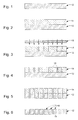
- a silicon wafer 12 is shown before carrying out the method according to the invention.
- the figure 2 illustrates a step of depositing a sacrificial layer 14 on the upper face of the silicon wafer 12.
- the figure 3 illustrates the treatment of the sacrificial layer 14, through a mask 16, for locally modifying the structure of the sacrificial layer 14 so as to draw on the silicon plate 12 a pattern representing a series of needles 10.
- the sacrificial layer 14 is developed, that is to say that the treated sacrificial layer portions 14 have been eliminated, so that the sacrificial layer 14 locally reveals portions 18 of the upper face of the silicon plate 12 .
- the silicon wafer 12 has been etched through the sacrificial layer, preferably by an anisotropic etching technique, so that the pattern representing the needles 10 is now drawn in the thickness of the silicon wafer 12.
- the remaining sacrificial layer 14 is then removed, as shown in FIG. figure 6 .
- a silicon wafer 12 is then obtained in which the needles 10 are pre-cut and retained attached to the body of the wafer 12 by material bridges, as shown in FIGS. Figures 7a and 7b .
- the final step in the manufacture of the needles 10 is to detach the needles from the silicon wafer 12.
- the method according to the invention may comprise at least one step during which a coating, for example metal, is deposited on the silicon forming the needles 10.
- a coating for example metal
- This coating may be deposited according to chemical or physical deposition techniques. vapor phase (“Chemical Vapor Deposition” or “Physical Vapor Deposition”).
- the method according to the invention may also comprise a chemical and / or thermal treatment step applied to the surface of the silicon forming the needles 10, for example in order to modify the surface appearance of the silicon.
- etching steps can also be implemented so as to modify the surface appearance of the silicon, or so as to modify the surface appearance of a coating deposited on the silicon, by producing geometric patterns or others, which makes it possible to obtain interesting optical effects.
- Such geometric patterns may, for example, give a guilloche-like appearance to the surface of the needles 10 made in the silicon.
- Such etching steps can be implemented when the needles 10 are still carried by the silicon wafer 12.
- the upper face of the needle 10 is provided with geometric patterns 24 in relief which were made by etching silicon.
- a metal deposit 26 has been made on these geometric patterns 24 which gives the needle 10 a guilloché metallic exterior appearance. It is noted that such a result would be very difficult to obtain in the case of a needle 10 whose main body 11 is metal.
- two longitudinal facets 28 were etched in the upper face of the needle 10.
- the patterns 24 and the facets 28 may have curved profiles so as to form corrugations on the surface of the needle 10.
- the method of manufacturing needles 10 according to the invention makes it possible to easily produce needles 10 having a variety of shapes and external aspects.
- the method according to the invention can be implemented in parallel on several silicon plates 12, so as to simultaneously produce, in several silicon plates 12, needles 10 of similar characteristics.
- FIG 8 there is shown a watch 20 which is provided with at least one silicon needle 10 made according to the method according to the invention.
- Each needle 10 is intended to be rotatably connected to an axis or a wheel of the watch movement (not shown) of the watch 20.
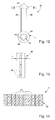
- the needle 10 is provided here with a pin hole 32 intended to be driven on a drive shaft 34.
- the internal axial surface of the pinhole 32 is provided with a layer 36 of material intended to enable the needle 10 to be driven by deformation of the layer 36 or by sliding against the layer 36, limiting the risks of rupture of the main body 11.
- the needle 10 according to the invention can be glued or welded to the drive shaft 34.
- an integrated circuit element 22 is made in the thickness of the silicon plate 12, in the body 11 of the needle 10.
- the integrated circuit element 22 can be produced, according to conventional microelectronics manufacturing technologies, before, during, or after the implementation of the manufacturing method according to the invention.
- elements 22 of integrated circuit may be previously made in the silicon wafer 12 as shown in FIG. figure 1 from which needles 10 are made.
- the integrated circuit element 22 can be electrically connected to the control circuit of the watch 20, through the rotation shaft of the needle 10.
- the integrated circuit element 22 comprises, for example, a light-emitting diode integrated in the thickness of the needle 10.
- the needle 10 can thus be illuminated from the inside, by exploiting the transparency properties of the silicon.
- the integrated circuit element 22 may include a sensor provided to provide the control circuit of the watch 20 with indications of the angular position of the needle 10 relative to the dial.
- the needle 10 is made entirely of silicon, that is to say that its main body 11, which forms the mechanical structure of the needle 10, is made of silicon and defines the outer shape of the needle 10.
- the main body 11 may be covered with one or more layers of coatings such as metal coatings.
- the main body 11 has an annular proximal portion 38 in which is arranged the axis hole 32 to allow the mounting of the needle 10 on the drive shaft 34 of the watch 20.
- the Axis hole 32 is provided to be fitted to the drive shaft 34, so that attachment of the needle 10 to the drive shaft 34 is similar to driving.
- the pin hole 32 is here provided with flexible elements 40 in the form of tongues which are formed in one piece with the proximal portion 38 of the main body 11 and which project on the inner surface of the pinhole 32
- the flexible elements 40 are provided to deform elastically during assembly of the needle 10 on the drive shaft 34.
- the flexible elements 40 exert a clamping force on the drive shaft 34 which allows to axially retain the needle 10 on the drive shaft 34 and to link these two elements in rotation.
- the flexible elements 40 are preferably formed during the micromachining step of the silicon plate 12.
- the main body 11 also comprises a distal portion 42 which constitutes the indicator portion of the needle 10.
- the distal portion 42 here has the shape of a triangle but it could take any other suitable form to indicate a determined angular position on the dial of the timepiece 20.
- the distal portion 42 is connected to the proximal portion 38 by two beams 44, 46 whose width 11, in a plane transverse to the drive axis 34, is between thirty and two hundred microns, and is preferably equal to fifty microns.
- the width 11 of fifty microns offers a good compromise between the rigidity and the fineness of the beam 44, 46.
- a needle 10 is thus obtained, of which practically only the proximal portion 38 and the distal portion 42 are visible, when the user of the watch 20 consults the indications given by the needle 10, in particular in plan view.
- the small width 11 makes the beams 44, 46 virtually invisible to the naked eye and thus render the elements under the needle 10, between the proximal portion 38 and the distal portion 42, are more clearly visible, in particular elements displayed on the dial of the watch 20.
- the use of these almost invisible beams 44, 46 makes it possible to offer more freedom in the drawing of the needle 10, by concealing a part of the structure of the needle 10.
- the needle 10 according to the invention may comprise more than two beams 44, 46.
- the number of beams 44, 46 may be chosen according to the shape of the needle 10, in particular depending on the shape of the distal portion 42, in order to ensure sufficient rigidity and shock resistance of the needle 10.
- the beams 46 may be provided with recesses 48 which are adapted to reduce the structure of the needle 10 without significantly penalizing its rigidity and impact resistance.
- the recesses 48 are constituted here by openings or windows which are aligned and distributed along the length of the beam 46 by defining material bridges between the two parallel parts forming the beam 46.
- the main body 11 of the needle 10 comprises, in its axial thickness, a plurality of generally cylindrical bores 50 which are substantially parallel to the drive axis 34 and which have a diameter of less than fifty microns, preferably a diameter between three and ten microns.
- the purpose of these holes 50 is to reduce the unbalance and inertia of the needle 10.
- the holes 50 are preferably arranged only in the distal portion 42, but they could also be arranged in the other parts of the main body 11.
- the holes 50 pass through the thickness of the main body 11 from one side to the other. They have dimensions small enough to be invisible to the naked eye for the user of the watch 20, so that they do not penalize the aesthetic appearance of the needle 10.
Landscapes
- Physics & Mathematics (AREA)
- General Physics & Mathematics (AREA)
- Engineering & Computer Science (AREA)
- Manufacturing & Machinery (AREA)
- Microelectronics & Electronic Packaging (AREA)
- Plasma & Fusion (AREA)
- Optics & Photonics (AREA)
- Micromachines (AREA)
- Crystals, And After-Treatments Of Crystals (AREA)
- Electromechanical Clocks (AREA)
- Apparatuses And Processes For Manufacturing Resistors (AREA)
- Electric Clocks (AREA)
- Glass Compositions (AREA)
- Liquid Crystal (AREA)
- Devices For Indicating Variable Information By Combining Individual Elements (AREA)
Priority Applications (1)
| Application Number | Priority Date | Filing Date | Title |
|---|---|---|---|
| EP10152831.3A EP2177957B1 (de) | 2005-05-12 | 2006-05-01 | Analoger Anzeiger aus kristallenem Material |
Applications Claiming Priority (3)
| Application Number | Priority Date | Filing Date | Title |
|---|---|---|---|
| EP05103979A EP1722281A1 (de) | 2005-05-12 | 2005-05-12 | Analoger Anzeiger aus kristallenem Material, Uhr mit solchem Anzeiger, und Herstellungsverfahren dafür |
| EP06754937A EP1882212B1 (de) | 2005-05-12 | 2006-05-01 | Aus kristallinem material hergestelltes analoganzeigeelement, mit einem anzeigeelement dieses typs ausgestattete uhr und herstellungsverfahren dafür |
| EP10152831.3A EP2177957B1 (de) | 2005-05-12 | 2006-05-01 | Analoger Anzeiger aus kristallenem Material |
Related Parent Applications (1)
| Application Number | Title | Priority Date | Filing Date |
|---|---|---|---|
| EP06754937.8 Division | 2006-05-01 |
Publications (3)
| Publication Number | Publication Date |
|---|---|
| EP2177957A2 true EP2177957A2 (de) | 2010-04-21 |
| EP2177957A3 EP2177957A3 (de) | 2011-10-26 |
| EP2177957B1 EP2177957B1 (de) | 2013-08-14 |
Family
ID=35708610
Family Applications (3)
| Application Number | Title | Priority Date | Filing Date |
|---|---|---|---|
| EP05103979A Withdrawn EP1722281A1 (de) | 2005-05-12 | 2005-05-12 | Analoger Anzeiger aus kristallenem Material, Uhr mit solchem Anzeiger, und Herstellungsverfahren dafür |
| EP06754937A Expired - Lifetime EP1882212B1 (de) | 2005-05-12 | 2006-05-01 | Aus kristallinem material hergestelltes analoganzeigeelement, mit einem anzeigeelement dieses typs ausgestattete uhr und herstellungsverfahren dafür |
| EP10152831.3A Expired - Lifetime EP2177957B1 (de) | 2005-05-12 | 2006-05-01 | Analoger Anzeiger aus kristallenem Material |
Family Applications Before (2)
| Application Number | Title | Priority Date | Filing Date |
|---|---|---|---|
| EP05103979A Withdrawn EP1722281A1 (de) | 2005-05-12 | 2005-05-12 | Analoger Anzeiger aus kristallenem Material, Uhr mit solchem Anzeiger, und Herstellungsverfahren dafür |
| EP06754937A Expired - Lifetime EP1882212B1 (de) | 2005-05-12 | 2006-05-01 | Aus kristallinem material hergestelltes analoganzeigeelement, mit einem anzeigeelement dieses typs ausgestattete uhr und herstellungsverfahren dafür |
Country Status (10)
| Country | Link |
|---|---|
| US (1) | US7618183B2 (de) |
| EP (3) | EP1722281A1 (de) |
| JP (1) | JP4993769B2 (de) |
| KR (1) | KR20080015402A (de) |
| CN (2) | CN101738924B (de) |
| AT (1) | ATE501468T1 (de) |
| CH (1) | CH696475A5 (de) |
| DE (1) | DE602006020560D1 (de) |
| TW (2) | TWI390370B (de) |
| WO (1) | WO2006122873A1 (de) |
Families Citing this family (35)
| Publication number | Priority date | Publication date | Assignee | Title |
|---|---|---|---|---|
| ATE467860T1 (de) * | 2006-11-09 | 2010-05-15 | Eta Sa Mft Horlogere Suisse | Montageelement, das dehnbare strukturen in form von gabeln umfasst, und dieses element umfassende uhr |
| DE602006011760D1 (de) * | 2006-11-09 | 2010-03-04 | Eta Sa Mft Horlogere Suisse | Montageelement, das zwei Reihen von dehnbaren Strukturen umfasst, und dieses Element umfassende Uhr |
| EP1921518B1 (de) * | 2006-11-09 | 2010-05-26 | ETA SA Manufacture Horlogère Suisse | Montageelement, das dehnbare Strukturen in Form von aufeinander liegenden Plättchen umfasst, und mit diesem Element ausgerüstete Uhr |
| EP1932804B1 (de) * | 2006-12-11 | 2017-03-22 | Mimotec S.A. | Silizium-Metall-Mischteile und damit verbundene Herstellungsverfahren |
| EP2011763B1 (de) * | 2007-07-03 | 2011-09-14 | EM Microelectronic-Marin SA | Verfahren zur Herstellung von mikromechanischen Teilen aus kristallinischem Material |
| EP2060534A1 (de) * | 2007-11-16 | 2009-05-20 | Nivarox-FAR S.A. | Mikromechanisches Bauteil aus Silizium-Metall-Verbundmaterial und Verfahren zu dessen Herstellung |
| EP2104008A1 (de) * | 2008-03-20 | 2009-09-23 | Nivarox-FAR S.A. | Monoblock-Regulierungsorgan und sein Herstellungsverfahren |
| CH699110A1 (fr) * | 2008-07-10 | 2010-01-15 | Swatch Group Res & Dev Ltd | Procédé de fabrication d'une pièce micromécanique. |
| CH699109A1 (fr) * | 2008-07-10 | 2010-01-15 | Swatch Group Res & Dev Ltd | Procédé de fabrication d'une pièce micromécanique. |
| EP2189854A1 (de) * | 2008-11-21 | 2010-05-26 | Nivarox-FAR S.A. | Verfahren zur Herstellung eines mikromechanischen Bauteils |
| EP2263971A1 (de) * | 2009-06-09 | 2010-12-22 | Nivarox-FAR S.A. | Mikromechanisches Verbundbauteil und sein Herstellungsverfahren |
| CN102347085B (zh) * | 2010-07-27 | 2013-12-04 | 比亚迪股份有限公司 | 用于仪表的指针、包括该指针的仪表及该指针的制造方法 |
| EP2469351A1 (de) | 2010-12-22 | 2012-06-27 | Nivarox-FAR S.A. | Zusammenbau eines Teils, das keinen Plastikbereich enthält |
| EP2469352A1 (de) | 2010-12-22 | 2012-06-27 | Nivarox-FAR S.A. | Zusammenbau eines Teils, das keinen Plastikbereich enthält |
| EP2503404B1 (de) * | 2011-03-23 | 2019-05-01 | Patek Philippe SA Genève | Verfahren zur Herstellung eines mechanischen Bauteils, insbesondere für Uhren |
| CN102167282A (zh) * | 2011-04-07 | 2011-08-31 | 天津海鸥表业集团有限公司 | 一种硅与金属复合材料的微结构加工方法 |
| EP2794463B1 (de) * | 2011-12-22 | 2017-03-15 | CSEM Centre Suisse d'Electronique et de Microtechnique SA - Recherche et Développement | Verfahren zur freisetzung eines mikromechanischen bauteils mit zerbrechlichen befestigungselementen |
| JP5447900B1 (ja) * | 2012-08-30 | 2014-03-19 | カシオ計算機株式会社 | 指針 |
| EP2952979B1 (de) * | 2014-06-03 | 2017-03-01 | Nivarox-FAR S.A. | Uhrkomponente aus fotostrukturierbarem glas |
| EP2988177A1 (de) * | 2014-08-21 | 2016-02-24 | Universo S.A. | Zeiger einer Armbanduhr |
| EP3035128B1 (de) * | 2014-12-17 | 2020-09-16 | Nivarox-FAR S.A. | Herstellungsverfahren eines Dekorelements einer Uhr oder eines Schmuckstücks |
| EP3141966B1 (de) | 2015-09-08 | 2018-05-09 | Nivarox-FAR S.A. | Erzeugungsverfahren einer dekoroberfläche eines mikromechanischen uhrenbauteils, und entsprechendes mikromechanisches uhrenbauteil |
| EP3168696A1 (de) * | 2015-11-11 | 2017-05-17 | Nivarox-FAR S.A. | Herstellungsverfahren für ein werkstück auf siliziumbasis mit mindestens einem motiv mit optischen täuschungselementen |
| US9791833B1 (en) | 2016-04-13 | 2017-10-17 | Google Inc. | Physical watch hands for a computerized watch |
| EP3249474B1 (de) * | 2016-05-26 | 2019-03-13 | ETA SA Manufacture Horlogère Suisse | Analoger zeiger |
| EP3425458A1 (de) * | 2017-07-07 | 2019-01-09 | ETA SA Manufacture Horlogère Suisse | Abtrennbares stück eines uhrenoszillators |
| EP3495894B1 (de) * | 2017-12-05 | 2023-01-04 | Rolex Sa | Verfahren zur herstellung einer uhrkomponente |
| JP7087873B2 (ja) * | 2018-09-20 | 2022-06-21 | セイコーエプソン株式会社 | 時計部品の製造方法 |
| EP3640745B1 (de) * | 2018-10-18 | 2023-02-22 | Patek Philippe SA Genève | Anzeigezeiger für uhr |
| EP3680731B1 (de) * | 2019-01-08 | 2022-06-08 | Patek Philippe SA Genève | Herstellungsverfahren von uhrkomponenten aus zerbrechlichem material |
| EP3907565A1 (de) | 2020-05-07 | 2021-11-10 | Patek Philippe SA Genève | Verfahren zur herstellung einer uhrenkomponente aus silizium |
| EP4312084B1 (de) | 2022-07-26 | 2026-06-24 | Nivarox-FAR S.A. | Verfahren zur herstellung einer siliziumspirale |
| JP7740302B2 (ja) * | 2023-06-20 | 2025-09-17 | カシオ計算機株式会社 | 時計 |
| JP2025002811A (ja) * | 2023-06-23 | 2025-01-09 | セイコーエプソン株式会社 | 時計用歯車の製造方法、板状部材、時計用歯車、及び時計 |
| DE102024128330B3 (de) * | 2024-10-01 | 2025-12-31 | Fabian Jurisch | Turmuhr und Verfahren zu deren Betrieb |
Family Cites Families (17)
| Publication number | Priority date | Publication date | Assignee | Title |
|---|---|---|---|---|
| DE7045090U (de) * | 1970-12-07 | 1971-03-11 | Rodi & Wienenberger Ag | Uhr, insbesondere armbanduhr |
| JPS4945753A (en) * | 1972-09-04 | 1974-05-01 | Seiko Instr & Electronics | Tokeito no shishin no seizohoho |
| JPS49114976U (de) * | 1973-01-25 | 1974-10-01 | ||
| DE7432697U (de) * | 1974-09-28 | 1976-04-01 | Philips Patentverwaltung Gmbh, 2000 Hamburg | Zeiger fuer eine uhr |
| JPS55167177U (de) * | 1979-05-18 | 1980-12-01 | ||
| JPS61245078A (ja) * | 1985-04-23 | 1986-10-31 | Citizen Watch Co Ltd | 時計用針 |
| JPS63115792U (de) * | 1987-01-20 | 1988-07-26 | ||
| JPH0580163A (ja) * | 1991-09-20 | 1993-04-02 | Seiko Epson Corp | 時計用外装部品 |
| CH682966B5 (fr) * | 1992-02-10 | 1994-06-30 | Gerald Genta | Aiguille pour pièce d'horlogerie. |
| US5569742A (en) * | 1994-06-22 | 1996-10-29 | The Salk Institute For Biological Studies | Centrally truncated NPY cyclic peptides |
| JP2799957B2 (ja) * | 1994-10-27 | 1998-09-21 | セイコークロック株式会社 | El発光針 |
| FR2731715B1 (fr) * | 1995-03-17 | 1997-05-16 | Suisse Electronique Microtech | Piece de micro-mecanique et procede de realisation |
| JP3928364B2 (ja) * | 2001-03-21 | 2007-06-13 | セイコーエプソン株式会社 | 時計 |
| US6863436B2 (en) * | 2001-12-19 | 2005-03-08 | Eta Sa Fabriques D'ebauches | Watch including a casing ring for a movement mounted in a case assembled via the bezel or via the back cover |
| US6871643B2 (en) * | 2002-10-18 | 2005-03-29 | Hoyt Usa, Inc. | Eccentric elements for a compound archery bow |
| ATE514124T1 (de) * | 2003-09-02 | 2011-07-15 | Patek Philippe Sa Geneve | Spiralrolle für uhr |
| CN2657055Y (zh) * | 2003-09-19 | 2004-11-17 | 杜一志 | 钟针具有显示效果的石英钟 |
-
2005
- 2005-05-12 CH CH00839/05A patent/CH696475A5/fr not_active IP Right Cessation
- 2005-05-12 EP EP05103979A patent/EP1722281A1/de not_active Withdrawn
-
2006
- 2006-05-01 EP EP06754937A patent/EP1882212B1/de not_active Expired - Lifetime
- 2006-05-01 WO PCT/EP2006/061949 patent/WO2006122873A1/fr not_active Ceased
- 2006-05-01 CN CN2009102250867A patent/CN101738924B/zh not_active Expired - Lifetime
- 2006-05-01 US US11/913,984 patent/US7618183B2/en not_active Expired - Lifetime
- 2006-05-01 KR KR1020077025971A patent/KR20080015402A/ko not_active Ceased
- 2006-05-01 DE DE602006020560T patent/DE602006020560D1/de not_active Expired - Lifetime
- 2006-05-01 AT AT06754937T patent/ATE501468T1/de not_active IP Right Cessation
- 2006-05-01 CN CN2006800164062A patent/CN101176044B/zh not_active Expired - Lifetime
- 2006-05-01 EP EP10152831.3A patent/EP2177957B1/de not_active Expired - Lifetime
- 2006-05-01 JP JP2008510536A patent/JP4993769B2/ja not_active Expired - Lifetime
- 2006-05-05 TW TW095116076A patent/TWI390370B/zh not_active IP Right Cessation
- 2006-05-05 TW TW101140503A patent/TWI463283B/zh not_active IP Right Cessation
Non-Patent Citations (2)
| Title |
|---|
| MARC MADOU: "Fundamentals of microfabrication", CRC PRESS |
| R.W. TJERKSTRA ET AL.: "Electrochemical Fabrication of Multiwalled Micro Channels", PROCEEDINGS OF MICRO TOTAL ANALYSIS SYSTEMS 98 WORKSHOP, pages 133 - 136 |
Also Published As
| Publication number | Publication date |
|---|---|
| KR20080015402A (ko) | 2008-02-19 |
| DE602006020560D1 (de) | 2011-04-21 |
| EP1882212A1 (de) | 2008-01-30 |
| US20080198702A1 (en) | 2008-08-21 |
| TWI390370B (zh) | 2013-03-21 |
| WO2006122873A1 (fr) | 2006-11-23 |
| CH696475A5 (fr) | 2007-06-29 |
| JP4993769B2 (ja) | 2012-08-08 |
| JP2009508084A (ja) | 2009-02-26 |
| TW200707142A (en) | 2007-02-16 |
| CN101176044A (zh) | 2008-05-07 |
| EP1722281A1 (de) | 2006-11-15 |
| CN101176044B (zh) | 2010-06-23 |
| EP2177957A3 (de) | 2011-10-26 |
| CN101738924A (zh) | 2010-06-16 |
| TWI463283B (zh) | 2014-12-01 |
| US7618183B2 (en) | 2009-11-17 |
| ATE501468T1 (de) | 2011-03-15 |
| EP1882212B1 (de) | 2011-03-09 |
| CN101738924B (zh) | 2012-07-04 |
| TW201312303A (zh) | 2013-03-16 |
| HK1119788A1 (en) | 2009-03-13 |
| EP2177957B1 (de) | 2013-08-14 |
Similar Documents
| Publication | Publication Date | Title |
|---|---|---|
| EP2177957B1 (de) | Analoger Anzeiger aus kristallenem Material | |
| EP3035128B1 (de) | Herstellungsverfahren eines Dekorelements einer Uhr oder eines Schmuckstücks | |
| EP3083487B1 (de) | Verfahren zur herstellung einer uhrenkomponente | |
| EP2326995B1 (de) | Getriebesystem für uhrwerk | |
| EP2145856B1 (de) | Verfahren zur Herstellung eines mikromechanischen Bauteils | |
| EP2145857B1 (de) | Verfahren zur Herstellung eines mikromechanischen Bauteils | |
| EP2579104B1 (de) | Herstellungsverfahren eines Verbunduhrwerks | |
| EP3088969B1 (de) | Thermocompensierte spiralfeder und verfahren zu deren herstellung | |
| CH700640B1 (fr) | Pièce d'horlogerie allegée et renforcée. | |
| EP3839659B1 (de) | Verfahren zur dekoration eines mechanischen bauteils | |
| EP4170435A1 (de) | Verfahren zur herstellung eines verkleidungsteils, insbesondere eines verkleidungsteils für uhren | |
| EP2784600A2 (de) | Herstellungsverfahren eines mikromechanischen Bauteils, das im wesentlichen eben ist, und mikromechanisches Bauteil, das mindestens einen Teil aus Siliziumoxid umfasst | |
| EP3814553B1 (de) | Herstellungsverfahren von dekorteilen | |
| EP4348357A1 (de) | Verfahren zur herstellung einer uhrwerkskomponente | |
| EP3168697B1 (de) | Herstellungsverfahren für ein werkstück auf siliziumbasis mit mindestens einem motiv mit optischen täuschungselementen | |
| CH719085A2 (fr) | Procédé de fabrication d'une pièce d'habillage, notamment d'une pièce d'horlogerie. | |
| EP4640917A1 (de) | Verfahren zum dekorieren eines substrats durch auftragen einer maskenschicht auf sol-gel-basis zur herstellung eines verkleidungsteils | |
| CH719929A2 (fr) | Procédé de fabrication d'un composant horloger en silicium. | |
| EP4312084A1 (de) | Verfahren zur herstellung einer siliziumspirale | |
| CH716363B1 (fr) | Procédé de décoration d'une pièce mécanique. | |
| CH713854A2 (fr) | Procédé de fabrication d'une pièce micromécanique. |
Legal Events
| Date | Code | Title | Description |
|---|---|---|---|
| PUAI | Public reference made under article 153(3) epc to a published international application that has entered the european phase |
Free format text: ORIGINAL CODE: 0009012 |
|
| AC | Divisional application: reference to earlier application |
Ref document number: 1882212 Country of ref document: EP Kind code of ref document: P |
|
| AK | Designated contracting states |
Kind code of ref document: A2 Designated state(s): AT BE BG CH CY CZ DE DK EE ES FI FR GB GR HU IE IS IT LI LT LU LV MC NL PL PT RO SE SI SK TR |
|
| RIN1 | Information on inventor provided before grant (corrected) |
Inventor name: BLONDEAU, FABIEN Inventor name: FLEURY, EMMANUEL Inventor name: MEISTER, PIERRE-ANDRE Inventor name: ZANETTA, ANDRE |
|
| PUAL | Search report despatched |
Free format text: ORIGINAL CODE: 0009013 |
|
| AK | Designated contracting states |
Kind code of ref document: A3 Designated state(s): AT BE BG CH CY CZ DE DK EE ES FI FR GB GR HU IE IS IT LI LT LU LV MC NL PL PT RO SE SI SK TR |
|
| RIC1 | Information provided on ipc code assigned before grant |
Ipc: G04B 45/02 20060101ALI20110919BHEP Ipc: G04D 3/00 20060101ALI20110919BHEP Ipc: G04B 19/04 20060101AFI20110919BHEP Ipc: B81C 1/00 20060101ALI20110919BHEP |
|
| 17P | Request for examination filed |
Effective date: 20120426 |
|
| GRAP | Despatch of communication of intention to grant a patent |
Free format text: ORIGINAL CODE: EPIDOSNIGR1 |
|
| GRAS | Grant fee paid |
Free format text: ORIGINAL CODE: EPIDOSNIGR3 |
|
| GRAA | (expected) grant |
Free format text: ORIGINAL CODE: 0009210 |
|
| AC | Divisional application: reference to earlier application |
Ref document number: 1882212 Country of ref document: EP Kind code of ref document: P |
|
| AK | Designated contracting states |
Kind code of ref document: B1 Designated state(s): AT BE BG CH CY CZ DE DK EE ES FI FR GB GR HU IE IS IT LI LT LU LV MC NL PL PT RO SE SI SK TR |
|
| REG | Reference to a national code |
Ref country code: GB Ref legal event code: FG4D Free format text: NOT ENGLISH |
|
| REG | Reference to a national code |
Ref country code: CH Ref legal event code: EP Ref country code: AT Ref legal event code: REF Ref document number: 627185 Country of ref document: AT Kind code of ref document: T Effective date: 20130815 |
|
| REG | Reference to a national code |
Ref country code: CH Ref legal event code: NV Representative=s name: ICB INGENIEURS CONSEILS EN BREVETS SA, CH |
|
| REG | Reference to a national code |
Ref country code: IE Ref legal event code: FG4D Free format text: LANGUAGE OF EP DOCUMENT: FRENCH |
|
| REG | Reference to a national code |
Ref country code: DE Ref legal event code: R096 Ref document number: 602006037914 Country of ref document: DE Effective date: 20131010 |
|
| REG | Reference to a national code |
Ref country code: NL Ref legal event code: VDEP Effective date: 20130814 Ref country code: AT Ref legal event code: MK05 Ref document number: 627185 Country of ref document: AT Kind code of ref document: T Effective date: 20130814 |
|
| REG | Reference to a national code |
Ref country code: LT Ref legal event code: MG4D |
|
| PG25 | Lapsed in a contracting state [announced via postgrant information from national office to epo] |
Ref country code: PT Free format text: LAPSE BECAUSE OF FAILURE TO SUBMIT A TRANSLATION OF THE DESCRIPTION OR TO PAY THE FEE WITHIN THE PRESCRIBED TIME-LIMIT Effective date: 20131216 Ref country code: AT Free format text: LAPSE BECAUSE OF FAILURE TO SUBMIT A TRANSLATION OF THE DESCRIPTION OR TO PAY THE FEE WITHIN THE PRESCRIBED TIME-LIMIT Effective date: 20130814 Ref country code: IS Free format text: LAPSE BECAUSE OF FAILURE TO SUBMIT A TRANSLATION OF THE DESCRIPTION OR TO PAY THE FEE WITHIN THE PRESCRIBED TIME-LIMIT Effective date: 20131214 Ref country code: LT Free format text: LAPSE BECAUSE OF FAILURE TO SUBMIT A TRANSLATION OF THE DESCRIPTION OR TO PAY THE FEE WITHIN THE PRESCRIBED TIME-LIMIT Effective date: 20130814 Ref country code: SE Free format text: LAPSE BECAUSE OF FAILURE TO SUBMIT A TRANSLATION OF THE DESCRIPTION OR TO PAY THE FEE WITHIN THE PRESCRIBED TIME-LIMIT Effective date: 20130814 Ref country code: CY Free format text: LAPSE BECAUSE OF FAILURE TO SUBMIT A TRANSLATION OF THE DESCRIPTION OR TO PAY THE FEE WITHIN THE PRESCRIBED TIME-LIMIT Effective date: 20130828 |
|
| PG25 | Lapsed in a contracting state [announced via postgrant information from national office to epo] |
Ref country code: SI Free format text: LAPSE BECAUSE OF FAILURE TO SUBMIT A TRANSLATION OF THE DESCRIPTION OR TO PAY THE FEE WITHIN THE PRESCRIBED TIME-LIMIT Effective date: 20130814 Ref country code: FI Free format text: LAPSE BECAUSE OF FAILURE TO SUBMIT A TRANSLATION OF THE DESCRIPTION OR TO PAY THE FEE WITHIN THE PRESCRIBED TIME-LIMIT Effective date: 20130814 Ref country code: PL Free format text: LAPSE BECAUSE OF FAILURE TO SUBMIT A TRANSLATION OF THE DESCRIPTION OR TO PAY THE FEE WITHIN THE PRESCRIBED TIME-LIMIT Effective date: 20130814 Ref country code: LV Free format text: LAPSE BECAUSE OF FAILURE TO SUBMIT A TRANSLATION OF THE DESCRIPTION OR TO PAY THE FEE WITHIN THE PRESCRIBED TIME-LIMIT Effective date: 20130814 Ref country code: GR Free format text: LAPSE BECAUSE OF FAILURE TO SUBMIT A TRANSLATION OF THE DESCRIPTION OR TO PAY THE FEE WITHIN THE PRESCRIBED TIME-LIMIT Effective date: 20131115 |
|
| PG25 | Lapsed in a contracting state [announced via postgrant information from national office to epo] |
Ref country code: CY Free format text: LAPSE BECAUSE OF FAILURE TO SUBMIT A TRANSLATION OF THE DESCRIPTION OR TO PAY THE FEE WITHIN THE PRESCRIBED TIME-LIMIT Effective date: 20130814 |
|
| PG25 | Lapsed in a contracting state [announced via postgrant information from national office to epo] |
Ref country code: SK Free format text: LAPSE BECAUSE OF FAILURE TO SUBMIT A TRANSLATION OF THE DESCRIPTION OR TO PAY THE FEE WITHIN THE PRESCRIBED TIME-LIMIT Effective date: 20130814 Ref country code: RO Free format text: LAPSE BECAUSE OF FAILURE TO SUBMIT A TRANSLATION OF THE DESCRIPTION OR TO PAY THE FEE WITHIN THE PRESCRIBED TIME-LIMIT Effective date: 20130814 Ref country code: EE Free format text: LAPSE BECAUSE OF FAILURE TO SUBMIT A TRANSLATION OF THE DESCRIPTION OR TO PAY THE FEE WITHIN THE PRESCRIBED TIME-LIMIT Effective date: 20130814 Ref country code: NL Free format text: LAPSE BECAUSE OF FAILURE TO SUBMIT A TRANSLATION OF THE DESCRIPTION OR TO PAY THE FEE WITHIN THE PRESCRIBED TIME-LIMIT Effective date: 20130814 Ref country code: DK Free format text: LAPSE BECAUSE OF FAILURE TO SUBMIT A TRANSLATION OF THE DESCRIPTION OR TO PAY THE FEE WITHIN THE PRESCRIBED TIME-LIMIT Effective date: 20130814 Ref country code: CZ Free format text: LAPSE BECAUSE OF FAILURE TO SUBMIT A TRANSLATION OF THE DESCRIPTION OR TO PAY THE FEE WITHIN THE PRESCRIBED TIME-LIMIT Effective date: 20130814 |
|
| PG25 | Lapsed in a contracting state [announced via postgrant information from national office to epo] |
Ref country code: ES Free format text: LAPSE BECAUSE OF FAILURE TO SUBMIT A TRANSLATION OF THE DESCRIPTION OR TO PAY THE FEE WITHIN THE PRESCRIBED TIME-LIMIT Effective date: 20130814 Ref country code: IT Free format text: LAPSE BECAUSE OF FAILURE TO SUBMIT A TRANSLATION OF THE DESCRIPTION OR TO PAY THE FEE WITHIN THE PRESCRIBED TIME-LIMIT Effective date: 20130814 |
|
| PLBE | No opposition filed within time limit |
Free format text: ORIGINAL CODE: 0009261 |
|
| STAA | Information on the status of an ep patent application or granted ep patent |
Free format text: STATUS: NO OPPOSITION FILED WITHIN TIME LIMIT |
|
| 26N | No opposition filed |
Effective date: 20140515 |
|
| REG | Reference to a national code |
Ref country code: DE Ref legal event code: R097 Ref document number: 602006037914 Country of ref document: DE Effective date: 20140515 |
|
| PG25 | Lapsed in a contracting state [announced via postgrant information from national office to epo] |
Ref country code: LU Free format text: LAPSE BECAUSE OF FAILURE TO SUBMIT A TRANSLATION OF THE DESCRIPTION OR TO PAY THE FEE WITHIN THE PRESCRIBED TIME-LIMIT Effective date: 20140501 |
|
| PG25 | Lapsed in a contracting state [announced via postgrant information from national office to epo] |
Ref country code: MC Free format text: LAPSE BECAUSE OF FAILURE TO SUBMIT A TRANSLATION OF THE DESCRIPTION OR TO PAY THE FEE WITHIN THE PRESCRIBED TIME-LIMIT Effective date: 20130814 |
|
| REG | Reference to a national code |
Ref country code: IE Ref legal event code: MM4A |
|
| PG25 | Lapsed in a contracting state [announced via postgrant information from national office to epo] |
Ref country code: IE Free format text: LAPSE BECAUSE OF NON-PAYMENT OF DUE FEES Effective date: 20140501 |
|
| REG | Reference to a national code |
Ref country code: FR Ref legal event code: PLFP Year of fee payment: 11 |
|
| PG25 | Lapsed in a contracting state [announced via postgrant information from national office to epo] |
Ref country code: BG Free format text: LAPSE BECAUSE OF FAILURE TO SUBMIT A TRANSLATION OF THE DESCRIPTION OR TO PAY THE FEE WITHIN THE PRESCRIBED TIME-LIMIT Effective date: 20130814 |
|
| PG25 | Lapsed in a contracting state [announced via postgrant information from national office to epo] |
Ref country code: HU Free format text: LAPSE BECAUSE OF FAILURE TO SUBMIT A TRANSLATION OF THE DESCRIPTION OR TO PAY THE FEE WITHIN THE PRESCRIBED TIME-LIMIT; INVALID AB INITIO Effective date: 20060501 Ref country code: BE Free format text: LAPSE BECAUSE OF FAILURE TO SUBMIT A TRANSLATION OF THE DESCRIPTION OR TO PAY THE FEE WITHIN THE PRESCRIBED TIME-LIMIT Effective date: 20140531 Ref country code: TR Free format text: LAPSE BECAUSE OF FAILURE TO SUBMIT A TRANSLATION OF THE DESCRIPTION OR TO PAY THE FEE WITHIN THE PRESCRIBED TIME-LIMIT Effective date: 20130814 |
|
| REG | Reference to a national code |
Ref country code: FR Ref legal event code: PLFP Year of fee payment: 12 |
|
| REG | Reference to a national code |
Ref country code: FR Ref legal event code: PLFP Year of fee payment: 13 |
|
| P01 | Opt-out of the competence of the unified patent court (upc) registered |
Effective date: 20230611 |
|
| PGFP | Annual fee paid to national office [announced via postgrant information from national office to epo] |
Ref country code: DE Payment date: 20250423 Year of fee payment: 20 |
|
| PGFP | Annual fee paid to national office [announced via postgrant information from national office to epo] |
Ref country code: GB Payment date: 20250423 Year of fee payment: 20 |
|
| PGFP | Annual fee paid to national office [announced via postgrant information from national office to epo] |
Ref country code: FR Payment date: 20250423 Year of fee payment: 20 |
|
| PGFP | Annual fee paid to national office [announced via postgrant information from national office to epo] |
Ref country code: CH Payment date: 20250601 Year of fee payment: 20 |
|
| REG | Reference to a national code |
Ref country code: CH Ref legal event code: H14 Free format text: ST27 STATUS EVENT CODE: U-0-0-H10-H14 (AS PROVIDED BY THE NATIONAL OFFICE) Effective date: 20260501 Ref country code: DE Ref legal event code: R071 Ref document number: 602006037914 Country of ref document: DE |
|
| REG | Reference to a national code |
Ref country code: GB Ref legal event code: PE20 Expiry date: 20260430 |
|
| PG25 | Lapsed in a contracting state [announced via postgrant information from national office to epo] |
Ref country code: GB Free format text: LAPSE BECAUSE OF EXPIRATION OF PROTECTION Effective date: 20260430 |