EP2185372B1 - Hakenkupplung - Google Patents
Hakenkupplung Download PDFInfo
- Publication number
- EP2185372B1 EP2185372B1 EP08785491A EP08785491A EP2185372B1 EP 2185372 B1 EP2185372 B1 EP 2185372B1 EP 08785491 A EP08785491 A EP 08785491A EP 08785491 A EP08785491 A EP 08785491A EP 2185372 B1 EP2185372 B1 EP 2185372B1
- Authority
- EP
- European Patent Office
- Prior art keywords
- hook
- blocking
- blocking lever
- triggering
- hook coupling
- Prior art date
- Legal status (The legal status is an assumption and is not a legal conclusion. Google has not performed a legal analysis and makes no representation as to the accuracy of the status listed.)
- Not-in-force
Links
- 230000008878 coupling Effects 0.000 title claims abstract description 53
- 238000010168 coupling process Methods 0.000 title claims abstract description 53
- 238000005859 coupling reaction Methods 0.000 title claims abstract description 53
- 230000000903 blocking effect Effects 0.000 claims abstract description 59
- 238000006073 displacement reaction Methods 0.000 claims abstract description 13
- 230000000295 complement effect Effects 0.000 claims description 4
- 230000000284 resting effect Effects 0.000 claims 1
- 230000000052 comparative effect Effects 0.000 description 6
- 230000015572 biosynthetic process Effects 0.000 description 5
- 230000006835 compression Effects 0.000 description 3
- 238000007906 compression Methods 0.000 description 3
- 230000000694 effects Effects 0.000 description 3
- 210000004072 lung Anatomy 0.000 description 2
- 239000011324 bead Substances 0.000 description 1
- 238000004519 manufacturing process Methods 0.000 description 1
- 230000002093 peripheral effect Effects 0.000 description 1
- 230000036316 preload Effects 0.000 description 1
- 239000007787 solid Substances 0.000 description 1
Images


Classifications
-
- B—PERFORMING OPERATIONS; TRANSPORTING
- B60—VEHICLES IN GENERAL
- B60D—VEHICLE CONNECTIONS
- B60D1/00—Traction couplings; Hitches; Draw-gear; Towing devices
- B60D1/01—Traction couplings or hitches characterised by their type
- B60D1/04—Hook or hook-and-hasp couplings
-
- F—MECHANICAL ENGINEERING; LIGHTING; HEATING; WEAPONS; BLASTING
- F16—ENGINEERING ELEMENTS AND UNITS; GENERAL MEASURES FOR PRODUCING AND MAINTAINING EFFECTIVE FUNCTIONING OF MACHINES OR INSTALLATIONS; THERMAL INSULATION IN GENERAL
- F16B—DEVICES FOR FASTENING OR SECURING CONSTRUCTIONAL ELEMENTS OR MACHINE PARTS TOGETHER, e.g. NAILS, BOLTS, CIRCLIPS, CLAMPS, CLIPS OR WEDGES; JOINTS OR JOINTING
- F16B45/00—Hooks; Eyes
- F16B45/02—Hooks with pivoting or elastically bending closing member
- F16B45/023—Hooks with pivoting or elastically bending closing member the closing member pivoting about an axis perpendicular to the plane of the hook
-
- F—MECHANICAL ENGINEERING; LIGHTING; HEATING; WEAPONS; BLASTING
- F16—ENGINEERING ELEMENTS AND UNITS; GENERAL MEASURES FOR PRODUCING AND MAINTAINING EFFECTIVE FUNCTIONING OF MACHINES OR INSTALLATIONS; THERMAL INSULATION IN GENERAL
- F16B—DEVICES FOR FASTENING OR SECURING CONSTRUCTIONAL ELEMENTS OR MACHINE PARTS TOGETHER, e.g. NAILS, BOLTS, CIRCLIPS, CLAMPS, CLIPS OR WEDGES; JOINTS OR JOINTING
- F16B45/00—Hooks; Eyes
- F16B45/02—Hooks with pivoting or elastically bending closing member
- F16B45/024—Hooks with pivoting or elastically bending closing member and having means biasing the closing member about the pivot
-
- F—MECHANICAL ENGINEERING; LIGHTING; HEATING; WEAPONS; BLASTING
- F16—ENGINEERING ELEMENTS AND UNITS; GENERAL MEASURES FOR PRODUCING AND MAINTAINING EFFECTIVE FUNCTIONING OF MACHINES OR INSTALLATIONS; THERMAL INSULATION IN GENERAL
- F16B—DEVICES FOR FASTENING OR SECURING CONSTRUCTIONAL ELEMENTS OR MACHINE PARTS TOGETHER, e.g. NAILS, BOLTS, CIRCLIPS, CLAMPS, CLIPS OR WEDGES; JOINTS OR JOINTING
- F16B45/00—Hooks; Eyes
- F16B45/02—Hooks with pivoting or elastically bending closing member
- F16B45/027—Hooks with pivoting or elastically bending closing member and having position-locking means for the closing member
- F16B45/028—Hooks with pivoting or elastically bending closing member and having position-locking means for the closing member the position-locking means being pivotally connected
Definitions
- the present invention relates to a hook coupling with the features of the preamble of claim 1.
- a hook coupling is known with a hooking body having a hooking opening and a locking pawl, which is adjustable between an open position in which the hooking opening is at least as far open that a drawbar eye can be hooked to the hook body for producing a positive connection with this, and a closure position, in which the hooking opening is obstructed at least to the extent that a hooked to the hook body to stay on this is secured, wherein the hook clutch further comprises: a locking lever which is displaceable between a blocking position in which he an adjustment of the closure pawl from the closed position to Open position locks out, and a release position in which it allows an adjustment of the closure pawl from the closed position to the open position, and a triggering device, which in its normal position when the locking lever in the Sperrstellu ng, inhibits a displacement of the locking lever in the release position, and which allows when actuated from its normal position out a shift of the locking lever in the release position.
- a locking lever which is displaceable between a blocking
- a hook coupling with the features of the preamble of claim 1 is from the document US 3,475,037 A known.
- This publication discloses a simplified operability of the hook coupling with increased operational reliability by the triggering device has a hook member movably mounted release member which is pivotable between the normal position and a release position in which it allows the displacement of the locking lever in the release position.
- the release member is provided for easy movement pivotally mounted on the hook body.
- the triggering component is pivotable from the basic position into the release position.
- the object of the present invention is to increase the reliability, in particular with regard to the safety of the lock.
- position is not to be understood as a clearly defined or even lockable position, but is to be judged by definition only in terms of their property, whether it allows or inhibits the definition of designated movement of the component also designated.
- the release member is movably mounted on the hook body, since the hook body can take as a solid component even high forces easily.
- the release member is biased by the action of force in the basic position.
- movement of the triggering component is at least assisted or even automatically initiated in the basic position securing the coupling state of the hook coupling.
- the hook coupling from a constructive point of view may comprise at least one trigger lever biasing spring, which at one end on the triggering component and at the other end to a component of locking lever, hook body or locking pawl, preferably supported on the closure pawl.
- the release member biasing spring is supported on the lock pawl since it is then moved together with the lock pawl and thus does not interfere with the hooking aperture.
- the release member is movable to its normal position only when the locking lever is in the locked position.
- the locking lever is pivotally mounted in the closure pawl, so that it can then be safely brought into its blocking position when the closure pawl is in its closed position.
- the locking lever and the release component are pivotable in opposite directions according to the invention.
- the locking lever and the release member regardless of the direction of rotation to reduce the required space around a locking lever pivot axis and a parallel to this triggering component pivot axis be pivotable.
- the trigger member has a locking portion which is arranged in the basic position of the trigger member to achieve a positive connection in juxtaposition to or in contact with a Verriegeiungsalleabrough the locking lever. If one then adjusts the release component in the release position, then the locking portion is then removed from the locking counter portion, so that the locking portion no longer prevents the locking counterpart form-fitting in its movement.
- a particularly high reliability of the hook coupling against its unwanted opening can be achieved that in the basic position of the release member self-locking between locking lever and release member is achieved such that movement of the locking lever from the blocking position to the release position towards no movement of the trigger member from the basic position Tripping position causes.
- This desired self-locking can be particularly easily realized in the above-mentioned opposing pivoting of release member and locking lever.
- the storage of the locking lever fails, such as by breaking a pivot shaft or shaft of the Locking lever can still be a desired locking effect of the locking lever with a closed hook clutch (locking pawl is in the closed position) are ensured when the locking lever at its locking lever schwenkachsen für longitudinal end is partially rotationally symmetrical with respect to the locking lever pivot axis and this longitudinal end of a substantially complementary recess in the component storing the locking lever is surrounded over a predetermined angular range.
- the Sperrhebelschwenkachsen technicallyre longitudinal end of the locking lever part-cylindrical, partially spherical, partially conical and the like may be formed.
- the complementary recess is preferably located close to the boundary surface of the partially rotationally symmetrical longitudinal end facing it, preferably forming a gap of very small gap width, for example from 0.5 to 2.5 mm.
- the wrap angle, over which the complementary recess surrounds the partially rotationally symmetrical longitudinal end, should be selected so that the wrap does not affect the desired mobility of the lock lever.
- a pivotable locking lever between its locking position and its release position only needs to be pivoted by a few angular degrees, to ensure the desired locking effect even at about broken locking lever pivot axis or shaft a wrap angle of 140 ° to 180 °, preferably from 160 ° s to 180 ° can be selected.
- wrap angle of more than 180 ° are conceivable with a corresponding structural design of the locking lever.
- the trigger member has a driver, which at least during a portion of a pivoting movement of the trigger member from the basic position away the locking lever from the blocking position towards the release position takes along.
- the entrainment device is designed and provided on the release component such that the locking lever can be displaced from the blocking position into the release position by the release component by means of the entrainment device.
- the driver device In order to reduce the number of components which are necessary for the formation of the hook clutch discussed here, provision can be made for the driver device to serve as a release-component-side preload spring bearing.
- the entrainment device has a sliding surface which at least during a portion of the pivoting movement of the release member from the basic position to the release position in sliding engagement with a contact contour of the locking lever arrives.
- Such Gleitstromeingriff can be realized without additional components in a very simple manner.
- the closure pawl can be moved as desired between its closed position and its open position.
- the closure pawl is pivotally provided on the hook body or on a rigidly connected thereto component.
- the number of components required for the production of the hook coupling can be kept low, when the closure pawl and the release member are pivotable about a common pivot axis. If this is not the case, the hook coupling can be realized even in a small space when the locking pawl pivot axis, the locking lever pivot axis and the release member pivot axis are parallel to each other.
- the locking lever may have a latching contour, which in addition is designed to lock with a formed on the hook body counter-latching contour when the closure pawl reaches its open position.
- the closure latch can be held in an advantageous manner without additional components in its open position.
- the locking contour is provided on the locking lever such that the biasing force acting on the locking lever, which biases him to the blocking position, also for securing the locking, in particular overcoming locking, can be used.
- the closure pawl can only be pivoted from its closed position into its open position by one-handed actuating engagement on the triggering component if the closure pawl comprises a mechanical stop which limits the displacement region of the blocking lever near the release position against movement away from the blocking position.
- the release member is first moved from its normal position to its release position, so that the locking lever is no longer fixed in its locked position. Then, the release lever is moved beyond the release position of the basic position away until the driver device has entered the sliding engagement described above with the contact contour of the locking lever. Moving starting from this state, the release lever even further away from the basic position, the locking lever is taken by the entrainment and spent during the movement of the trigger member from its blocking position to its release position.
- counter stop surface of the hook body Against excessive opening while protecting a provided for the locking lever to ensure its blocking action counter stop surface of the hook body can be provided that the counter stop surface of the hook body, with which a stop surface of the locking lever in its locked position comes into abutting engagement, also for investment of an abutment portion of the closure pawl is formed, in such a way that the counter-abutment surface limits the adjustability of the closure pawl near the open position in the direction away from the closed position.
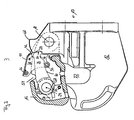
- a hook coupling according to the invention generally designated 10. It comprises a hook body 12 with a hooking opening 14 (see Fig. 4 and 5 ) And with a pivotally hinged on the hook body closure pawl 16. More precisely, the closure pawl 16 is pivotable about a closure pawl pivot axis 18 on the hook body 12 is provided.
- the hook body 12 and closure pawl 16 define a passage opening 22 in which a drawbar eye of a trailing vehicle can be accommodated.
- a locking lever 26 is pivoted about a locking lever pivot axis 24 parallel to the locking pawl pivot axis 18.
- the locking lever 26 is in its blocking position, that is, a front-side stop surface 28 is in contact with a counter-abutment surface 30 of the hook body.
- the closure flap 16 can not escape its position in FIG Fig. 2 shown closure position to be pivoted clockwise.
- the locking lever 26 is by a compression spring 32, which is stretched between the locking pawl 16 and a clamping extension 34 of the locking lever 26, in the in Fig. 2 biased locked position shown.
- the compression spring 32 is only in Fig. 2 represented and in the Fig. 3 to 5 omitted.
- the hook coupling 10 comprises a triggering device 36 pivotable about the pivot axis 18 on the hook body 12.
- This comprises a lever-like triggering component 38 Fig. 2 is the trigger member 38 shown in its normal position in which it inhibits movement of the locking lever 26 from its blocking position.
- the triggering component 38 in a cover part 40 on a locking portion 42 which is arranged in juxtaposition to a locking counter portion 44 of the locking lever 26.
- the locking counterpart portion 44 is replicated following an envelope at a distance, which is generated by the locking portion 44 upon pivoting of the triggering member 38 from the basic position to the release position.
- the triggering device 36 handles 46, which protrude in the lateral direction.
- a tension spring 48 in the in Fig. 2 biased basic position shown biased.
- the tension spring is set triggering component side on a the triggering member 38 passing through rod 50 and is fixed with its other longitudinal end to a catch ratchet fixed spring abutment 52.
- the tension spring 48 is for clarity only in the Fig. 2 represented and in the Fig. 3 to 5 omitted.
- depressions 54 are provided on the side legs 16 a and 16 b of the closure pawl (see in particular Fig. 3 to 5 ).
- the locking lever pivot near the longitudinal end of the locking lever 26 is formed as a sub-cylinder, wherein the cylinder axis of the sub-cylinder coincides with the locking lever pivot axis 24.
- a partially cylindrical recess 58 is formed with a small gap distance from the part-cylindrical formation 56 of the locking lever 26, which surrounds the teilzylindwitz training 56 of the locking lever 26 through an angle of about 170 °.
- the gap between the part-cylindrical formation 56 of the locking lever 26 and the part-cylindrical recess 58 in the closure pawl is between about 0.5 and 2.5 mm.
- the partially cylindrical recess 58 of the locking pawl 16 holds the locking lever 26 approximately in its in Fig. 2 Shown blocking position, so that even with a broken pivot axis or pivot shaft of the locking lever 26, the desired locking action of the locking lever 26 is maintained.
- the locking lever 26 is further pivoted by the Schmidtstromeingriff the rod 50 on the contact contour 60 in a counterclockwise direction until it is against a mechanical stop 62 (see Fig. 4 ) arrives at the lock pawl 16.
- the closure pawl 16 of the locking lever 26 and the trigger member 38 are braced against each other in a further pivotal movement of the trigger member 38 in a clockwise direction such that a pivoting movement of the trigger member 38 in a clockwise direction to a pivotal movement of the latch 16 in a clockwise direction leads (see Fig. 4 ), so that the hooking opening 14 is gradually released.
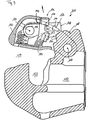
- Fig. 5 the closure pawl 16 is shown in its open position, wherein a contact portion 64 of the closure pawl 16 abuts against the abutment surface 30 of the hook body 12 so that a towing eye for coupling to the hook body 12 can not reach the counter stop surface 30 and damage it.
- the locking lever 26 is latched with a latching recess 66 on a latching counter-geometry 68 of the hook body under the action of the compression spring 32 surmountable.
- the closure pawl 16 by pressing in the counterclockwise direction, releasing the surmountable locking between locking lever 26 and hook body 12 back into the in Fig. 2 Shutter position shown to be moved. Due to the bias voltages of the individual components shown above, the locking pawl 16 automatically locks in its closed position against reopening.
- the opening operation of the pawl 16 can, as explained above, be carried out with one hand.
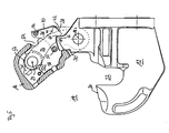
- a comparative example of a hook coupling is shown.
- the same or functionally identical components of the comparative example are denoted by the same reference numerals as corresponding components of the first embodiment, but increased by the number 100.
- the comparative example will be described below only insofar as it undercuts the first embodiment.
- the triggering component 138 in the comparative example is pivotably connected to the closure pawl 116 about a triggering component pivot axis 119.
- the trigger member 136 is not in the clockwise direction as in the first embodiment, but in the counterclockwise direction from the in Fig. 6 shown basic position in a locking lever 126 for movement from the locking position releasing release position movable.
- the trigger member 138 is connected by a torsion spring 148 in the in Fig. 6 biased basic position shown biased.
- One end leg of the torsion spring 148 rests on a rigidly connected to the trigger member 136 plastic buffer 151, while another, opposite end leg of the torsion spring 148 is supported on the lock pawl 116.
- the plastic buffer 151 has a bead 153, which serves as a driver device and, as in the first embodiment, in the basic position of the trigger member 138 spaced from a contact contour 160 of the locking lever 126, upon pivoting of the trigger member 138 from the normal position on the release position addition However, in abutting engagement with the system contour 160 passes, and thus pivots the locking lever 126 with continued pivotal movement of the trigger member 138 in the counterclockwise direction from the blocking position in the direction of the release position.
- a cover part 140 of the release component 138 is formed with a step to the pivot axis 119 of the release member 138 back.
- a free longitudinal end of the lid part 140 is formed as an extended cover, which is to prevent dirt entering the lock pawl.
- a step formation 145 interacting with the radial step of the cover part 140 is formed, which ensures that the pivot lever 126 can not be pivoted counterclockwise out of the locked position until the radial step of the cover part 140 the step formation 145 of the locking lever 126 has passed.
- the locking portion 142 of the release member 138 is hook-shaped, wherein the engagement surface 142 a of the locking portion 142 is a part-cylindrical peripheral surface with the release member pivot axis 119 as the central axis.
- the latch 116 can simply be moved clockwise from the closed position to the open position (see FIG Fig. 9 and 10 ).
- the basic position for the respective triggering component can only be achieved when the locking lever is in the blocking position.
Landscapes
- Engineering & Computer Science (AREA)
- General Engineering & Computer Science (AREA)
- Mechanical Engineering (AREA)
- Transportation (AREA)
- Lock And Its Accessories (AREA)
- Hooks, Suction Cups, And Attachment By Adhesive Means (AREA)
- Mechanical Operated Clutches (AREA)
- Vending Machines For Individual Products (AREA)
- Sewing Machines And Sewing (AREA)
- Invalid Beds And Related Equipment (AREA)
- Cookers (AREA)
Description
- Die vorliegende Erfindung betrifft eine Hakenkupplung mit den Merkmalen des Oberbegriffs von Anspruch 1.
- Aus der
US 2004/0239077 A1 ist beispielsweise eine Hakenkupplung bekannt mit einem eine Einhaköffnung aufweisenden Hakenkörper und einer Verschlussklinke, welche verstellbar ist zwischen einer Offenstellung, in welcher die Einhaköffnung zumindest soweit offen ist, dass eine Zugöse an dem Hakenkörper zur Herstellung einer Formschlussverbindung mit diesem einhakbar ist, und einer Verschlussstellung, in welcher die Einhaköffnung zumindest soweit versperrt ist, dass eine an dem Hakenkörper eingehakte Zugöse zum Verbleib an diesem gesichert ist, wobei die Hakenkupplung weiter umfasst: einen Sperrhebel, welcher verlagerbar ist zwischen einer Sperrstellung, in welcher er eine Verstellung der Verschlussklinke von der Verschlussstellung zur Offenstellung hin sperrt, und einer Freigabestellung, in welcher er eine Verstellung der Verschlussklinke von der Verschlussstellung zur Offenstellung hin gestattet, sowie eine Auslöseeinrichtung, welche in ihrer Grundstellung dann, wenn der Sperrhebel sich in der Sperrstellung befindet, eine Verlagerung des Sperrhebels in die Freigabestellung hemmt, und welche bei Betätigung aus ihrer Grundstellung heraus eine Verlagerung des Sperrhebels in die Freigabestellung erlaubt. Bei dieser Hakenkupplung ist die Auslöseeinrichtung beweglich am Sperrhebel gelagert, wobei sich die Auslöseeinrichtung an der Verschlussklinke abstützt und so eine Bewegung des Sperrhebels aus der Sperrstellung zur Freigabestellung hin hemmt. - Nachteilig an der aus der
US 2004/0239077 A1 bekannten Hakenkupplung ist zum einen die umständliche Bedienung, da zum Öffnen der Hakenkupplung, also zur Verstellung der Verschlussklinke in die Offenstellung, die Auslöseeinrichtung zunächst in einer ersten Richtung betätigt und der Sperrhebel in der derselben ersten Richtung bewegt werden muss, woraufhin nach der Verlagerung des Sperrhebels in die Freigabestellung die den Sperrhebel lagernde Verschlussklinke in die entgegengesetzte Richtung zur Offenstellung hin verstellt werden muss. - Darüber hinaus erscheint die aus der
US 2004/0239007 A1 bekannte Hakenkupplung in ihrer Betriebssicherheit verbesserungswürdig. Dann nämlich, wenn eine den Sperrhebel zum Verschwenken lagernde Schwenkwelle brechen sollte, kann sich der Sperrhebel ohne weiteres aus seiner Sperrstellung herausbewegen und seine Sperrwirkung einbüßen. - Eine Hakenkupplung mit den Merkmalen des Oberbegriffs von Anspruch 1 ist aus der Druckschrift
US 3,475,037 A bekannt. - Diese Druckschrift offenbart eine vereinfachte Betätigbarkeit der Hakenkupplung bei erhöhter Betriebssicherkeit, indem die Auslöseeinrichtung ein am Hakenkörper beweglich gelagertes Auslösebauteil aufweist, welches schwenkbar ist zwischen der Grundstellung und einer Auslösestellung, in welcher es die Verlagerung des Sperrhebels in die Freigabestellung erlaubt.
- Dabei ist das Auslösebauteil zur einfachen Bewegung verschwenkbar am Hakenkörper vorgesehen. Dabei ist das Auslösebauteil von der Grundstellung in die Auslösestellung verschwenkbar.
- Zur Sicherstellung einer möglichst einfachen aber robusten Bewegbarkeit des Sperrhebels ist auch dieser zwischen der Sperrstellung und der Freigabestellung schwenkbar ausgebildet.
- Die Aufgabe der vorliegenden Erfindung besteht in einer Erhöhung der Betriebssicherheit, insbesondere im Hinblick auf die Sicherheit der Verriegelung.
- Diese Aufgabe wird gelöst, indem bei einer gattungsgemäßen Hakenkupplung der Sperrhebel und das Auslösebauteil gegensinnig verschwenkbar sind.
- Die in dieser Anmeldung genannten Stellungen einzelner Bauteile der Hakenkupplung sind häufig dadurch gekenntzeichnet, dass sie eine Bewegung desselben oder eines anderen Bauteils gestatten oder hemmen. Dabei ist "Stellung" nicht als eindeutig definierte oder gar verrastbare Stellung zu verstehen, sondern ist definitionsgemäß lediglich hinsichtlich ihrer Eigenschaft zu beurteilen, ob sie die definitionsgemäß bezeichnete Bewegung des ebenfalls bezeichneten Bauteils gestattet oder hemmt.
- Bevorzugt ist das Auslösebauteil am Hakenkörper beweglich gelagert, da der Hakenkörper als massives Bauteil selbst hohe Kräfte problemlos auf nehmen kann.
- Zur Erhöhung der Betriebssicherheit der Hakenkupplung kann vorgesehen sein, dass das Auslösebauteil durch Krafteinwirkung in die Grundstellung vorgespannt ist. Dadurch wird eine Bewegung des Auslösebauteils in die den Kupplungszustand der Hakenkupplung sichernde Grundstellung zumindest unterstützt oder sogar selbsttätig eingeleitet.
- Hierzu kann die Hakenkupplung aus konstruktiver Sicht wenigstens eine Auslösehebel-Vorspannfeder umfassen, welche einenends am Auslösebauteil und andernends an einem Bauteil aus Sperrhebel, Hakenkörper oder Verschlussklinke, vorzugsweise an der Verschlussklinke abgestützt ist.
- Vorzugsweise ist die Auslösebauteil-Vorspannfeder an der Verschlussklinke abgestützt, da sie dann gemeinsam mit der Verschlussklinke bewegt wird und so die Einhaköffnung nicht stört.
- Je nach der benötigten Vorspannkraft können auch zwei oder mehr Auslösebauteil-Vorspannfedern vorgesehen sein.
- Zur weiteren Erhöhung der Betriebssicherheit kann daran gedacht sein, dass das Auslösebauteil nur dann in seine Grundstellung bewegbar ist, wenn sich der Sperrhebel in der Sperrstellung befindet.
- Vorteilhafterweise ist der Sperrhebel schwenkbar in der Verschlussklinke gelagert, so dass er dann sicher in seine Sperrstellung verbracht werden kann, wenn sich die Verschlussklinke in ihrer Verschlussstellung befindet.
- Wie weiter unten ausgeführt werden wird, ist es aus mehrerlei Hinsicht vorteilhaft, dass der Sperrhebel und das Auslösebauteil erfindungsgemäß gegensinnig verschwenkbar sind. Vorteilhafterweise können der Sperrhebel und das Auslösebauteil unabhängig vom jeweiligen Drehsinn zur Verringerung des benötigten Bauraums um eine Sperrhebel-Schwenkachse und eine zu dieser parallele Auslösebauteil-Schwenkachse schwenkbar sein.
- Zur besonders sicheren mechanischen Verriegelung des Sperrhebels in dessen Sperrstellung kann konstruktiv vorgesehen sein, dass das Auslösebauteil einen Verriegelungsabschnitt aufweist, welcher in der Grundstellung des Auslösebauteils zur Erzielung eines Formschlusses in Gegenüberstellung zu oder in Anlage an einem Verriegeiungsgegenabschnitt des Sperrhebels angeordnet ist. Verstellt man dann das Auslösebauteil in die Auslösestellung, so befindet sich der Verriegelungsabschnitt dann vom Verriegelungsgegenabschnitt entfernt, so dass der Verriegelungsabschnitt den Verriegelungsgegenabschnitt nicht mehr formschlüssig an seiner Bewegung hindert.
- Eine besonders hohe Betriebssicherheit der Hakenkupplung gegen ihr unerwünschtes Öffnen kann dadurch erreicht werden, dass in der Grundstellung des Auslösebauteils eine Selbsthemmung zwischen Sperrhebel und Auslösebauteil derart erreicht ist, dass eine Bewegung des Sperrhebels von der Sperrstellung zur Freigabestellung hin keine Bewegung des Auslösebauteils von der Grundstellung zur Auslösestellung hin bewirkt. Diese gewünschte Selbsthemmung kann bei der oben genannten gegensinnigen Verschwenkbarkeit von Auslösebauteil und Sperrhebel besonders einfach realisiert werden.
- Wenn, wie oben bereits angedeutet wurde, die Lagerung des Sperrhebels versagt, etwa durch Brechen einer Schwenkwelle oder -achse des Sperrhebels, kann dennoch eine gewünschte Sperrwirkung des Sperrhebels bei geschlossener Hakenkupplung (Verschlussklinke befindet sich in der Verschlussstellung) sichergestellt werden, wenn der Sperrhebel an seinem Sperrhebel-schwenkachsennäheren Längsende teilrotationssymmetrisch bezüglich der Sperrhebel-Schwenkachse ausgeführt ist und dieses Längsende von einer im Wesentlichen komplementären Ausnehmung in dem den Sperrhebel lagernden Bauteil über einen vorbestimmten Winkelbereich hinweg umgeben ist. Dabei kann das Sperrhebelschwenkachsennähere Längsende des Sperrhebels teilzylindrisch, teilsphärisch, teilkonisch und dergleichen ausgebildet sein. Die komplementäre Ausnehmung befindet sich vorzugsweise nahe an der zu ihr hin weisenden Begrenzungsfläche des teilrotationssymmetrischen Längsendes, vorzugsweise unter Bildung eines Spalts von sehr geringer Spaltbreite, etwa von 0,5 bis 2,5 mm.
- Der Umschlingungswinkel, über welchen hinweg die komplementäre Ausnehmung das teilrotationssymmetrische Längsende umgibt, sollte so gewählt sein, dass die Umschlingung die gewünschte Bewegbarkeit des Sperrhebels nicht beeinträchtigt. Da jedoch ein verschwenkbarer Sperrhebel zwischen seiner Sperrstellung und seiner Freigabestellung nur um wenige Winkelgrad verschwenkt werden muss, kann zur Sicherstellung der gewünschten Sperrwirkung auch bei etwa gebrochener Sperrhebel-Schwenkachse oder -welle ein Umschlingungswinkel von 140° bis 180°, vorzugsweise von 160°s bis 180° gewählt sein. Auch Umschlingungswinkel von mehr als 180° sind bei entsprechender konstruktiver Ausgestaltung des Sperrhebels denkbar.
- Zur sicheren gewünschten Verlagerung des Sperrhebels von dessen Sperrstellung in dessen Freigabestellung bei gleichzeitig sehr einfacher Bedienbarkeit kann vorgesehen sein, dass das Auslösebauteil eine Mitnehmereinrichtung aufweist, welche zumindest während eines Abschnitts einer Verschwenkbewegung des Auslösebauteils von der Grundstellung weg den Sperrhebel von der Sperrstellung in Richtung zur Freigabestellung hin mitnimmt. Vorzugsweise ist die Mitnehmereinrichtung derart ausgebildet und am Auslösebauteil vorgesehen, dass der Sperrhebel durch das Auslösebauteil vermittels der Mitnehmereinrichtung von der Sperrstellung in die Freigabestellung verlagerbar ist.
- Zur Verringerung der Anzahl an Bauteilen, welche zur Bildung der hier diskutierten Hakenkupplung notwendig sind, kann vorgesehen sein, dass die Mitnehmereinrichtung als auslösebauteilseitiges Vorspannfederlager dient.
- Zur Sicherstellung der Verlagerung des Sperrhebels von dessen Sperrstellung zu seiner Freigabestellung hin kann konstruktiv vorgesehen sein, dass die Mitnehmereinrichtung eine Gleitfläche aufweist, welche zumindest während eines Abschnitts der Verschwenkbewegung des Auslösebauteils von der Grundstellung in die Auslösestellung in Gleitanlageeingriff an eine Anlagekontur des Sperrhebels gelangt. Ein derartiger Gleitanlageeingriff kann ohne zusätzliche Bauteile in sehr einfacher Weise realisiert sein.
- Grundsätzlich kann vorgesehen sein, dass die Verschlussklinke beliebig zwischen ihrer Verschlussstellung und ihrer Offenstellung bewegbar ist. Vorzugsweise ist jedoch auch die Verschlussklinke schwenkbar am Hakenkörper oder an einem mit diesem starr verbundenen Bauteil vorgesehen. Dabei kann die Anzahl an zur Herstellung der Hakenkupplung benötigten Bauteilen gering gehalten werden, wenn die Verschlussklinke und das Auslösebauteil um eine gemeinsame Schwenkachse schwenkbar sind. Ist dies nicht der Fall, kann die Hakenkupplung selbst bei geringem Bauraum realisiert sein, wenn die Verschlussklinken-Schwenkachse, die Sperrhebel-Schwenkachse und die Auslösebauteil-Schwenkachse zueinander parallel sind.
- Zur Erhöhung der Betriebssicherheit kann der Sperrhebel zur Sperrstellung hin vorgespannt sein.
- Weiterhin kann der Sperrhebel eine Rastkontur aufweisen, welche dazu ausgebildet ist, mit einer am Hakenkörper ausgebildeten Gegenrastkontur zu verrasten, wenn die Verschlussklinke ihre Offenstellung erreicht. Dadurch kann die Verschlussklinke in vorteilhafter Weise ohne zusätzliche Bauteile in ihrer Offenstellung gehalten werden. Vorzugsweise ist die Rastkontur derart am Sperrhebel vorgesehen, dass die auf den Sperrhebel wirkende Vorspannkraft, die ihn zur Sperrstellung hin vorspannt, auch zur Sicherstellung der Verrastung, insbesondere überwindbaren Verrastung, genutzt werden kann.
- Zur besonders einfachen Betätigung der Verschlussklinke durch das Auslösebauteil sind diese vorteilhafterweise derart vorgesehen, dass das Auslösebauteil bei seiner Betätigung von der Grundstellung in die Auslösestellung und ggf. darüber hinaus im gleichen Drehsinn verschwenkt wird wie die Verschlussklinke bei ihrer Verstellung von der Verschlussstellung in die Offenstellung.
- Durch die oben beschriebene Mitnehmervorrichtung kann die Verschlussklinke lediglich durch einhändigen Betätigungsangriff an dem Auslösebauteil von ihrer Verschlussstellung in ihre Offenstellung verschwenkt werden, wenn die Verschlussklinke einen mechanischen Anschlag umfasst, welcher den Verlagerungsbereich des Sperrhebels nahe der Freigabestellung gegen eine Bewegung von der Sperrstellung weg begrenzt.
- In diesem Falle wird zunächst das Auslösebauteil aus seiner Grundstellung in seine Auslösestellung verbracht, so dass der Sperrhebel nicht länger in dessen Sperrstellung festgelegt ist. Dann wird der Auslösehebel über die Auslösestellung hinaus von der Grundstellung weg bewegt, bis die Mitnehmereinrichtung in den oben beschriebenen Gleitanlageeingriff mit der Anlagekontur des Sperrhebels gelangt ist. Bewegt man ausgehend von diesem Zustand den Auslösehebel noch weiter von der Grundstellung weg, so wird der Sperrhebel durch die Mitnehmereinrichtung mitgenommen und während der Bewegung des Auslösebauteils aus seiner Sperrstellung in seine Freigabestellung verbracht.
- Bewegt man das Auslösebauteil schließlich so weit, bis der Sperrhebel an dem gerade erwähnten mechanischen Anschlag zur Anlage kommt, so verspannen sich Verschlussklinke, Sperrhebel und Auslösebauteil gegeneinander, so dass bei noch einer weiteren Bewegung des Auslösebauteils von der Grundstellung weg die Verschlussklinke als Ganzes gleichsinnig mit dem Auslösebauteil verschwenkt wird.
- Gegen ein übermäßiges Öffnen bei gleichzeitigem Schutz einer für den Sperrhebel zur Sicherstellung von dessen Sperrwirkung vorgesehenen Gegenanschlagfläche des Hakenkörpers kann vorgesehen sein, dass die Gegenanschlagfläche des Hakenkörpers, mit welcher eine Anschlagfläche des Sperrhebels in dessen Sperrstellung in Anlageeingriff gelangt, auch zur Anlage eines Anlageabschnitts der Verschlussklinke daran ausgebildet ist, und zwar derart, dass die Gegenanschlagfläche die Verstellbarkeit der Verschlussklinke nahe der Offenstellung in Richtung von der Verschlussstellung weg begrenzt.
- Die vorliegende Erfindung wird im Folgenden anhand eines Ausführungsbeispiels näher erläutert werden. Es stellt dar:
- Fig. 1
- eine Draufsicht auf eine erfindungsgemäße erste Ausführungs- form einer Hakenkupplung,
- Fig. 2
- eine Teilschnittansicht der Hakenkupplung von
Fig. 1 mit der Verschlussklinke in der Verschlussstellung, - Fig. 3
- eine Teilschnittansicht der Hakenkupplung der
Fig. 1 und 2 bei Beginn eines Öffnungsvorgangs zum Öffnen der Hakenkupp- lung, - Fig. 4
- die Hakenkupplung der
Fig. 1 bis 3 mit fortgeschrittener Öff- nungsbetätigung, - Fig. 5
- die Hakenkupplung der
Fig. 1 bis 4 mit der Verschlussklinke in der Offenstellung, - Fig.6
- eine der
Fig. 2 entsprechende Teilschnittansicht eines vergleichsbeispiels einer Hakenkupp- lung, - Fig. 7
- eine Teilschnittansicht der Hakenkupplung von
Fig. 6 bei Beginn eines Öffnungsvorgangs zum Öffnen der Hakenkupplung, - Fig. 8
- die Hakenkupplung der
Fig. 6 und7 mit maximal von seiner Grundstellung entferntem Auslösebauteil, - Fig. 9
- die Hakenkupplung der
Fig. 6 bis 8 , wobei die Verschlussklinke sich zwischen ihrer Verschlussstellung und ihrer Offenstellung befindet, und - Fig. 10
- die Hakenkupplung der
Fig. 6 bis 9 mit der Verschlussklinke in der Offenstellung. - In den
Fig. 1 bis 5 ist eine erfindungsgemäße Hakenkupplung allgemein mit 10 bezeichnet. Sie umfasst einen Hakenkörper 12 mit einer Einhaköffnung 14 (sieheFig. 4 und5 ) und mit einer schwenkbar am Hakenkörper angelenkten Verschlussklinke 16. Genauer ist die Verschlussklinke 16 um eine Verschlussklinken-Schwenkachse 18 schwenkbar am Hakenkörper 12 vorgesehen. - In der in Fg. 2 dargestellten Verschlussstellung der Verschlussklinke 16, in welcher diese auf einer Auflagefläche 20 des Hakenkörpers 12 aufliegt und somit die Einhaköffnung 14 verschließt, definieren Hakenkörper 12 und Verschlussklinke 16 eine Durchgangsöffnung 22, in welcher eine Zugöse eines Nachlauffahrzeugs aufgenommen sein kann.
- An der Verschlussklinke 16 ist um eine zur Verschlussklinken-Schwenkachse 18 parallele Sperrhebel-Schwenkachse 24 ein Sperrhebel 26 schwenkbar angelenkt.
- Wie in
Fig. 2 dargestellt ist, befindet sich der Sperrhebel 26 in seiner Sperrstellung, d. h. eine stirnseitige Anschlagfläche 28 befindet sich in Anlage an einer Gegenanschlagfläche 30 des Hakenkörpers. Dadurch kann die Verschlusslkinke 16 nicht aus ihrer inFig. 2 gezeigten Verschlussstellung im Uhrzeigersinn verschwenkt werden. - Der Sperrhebel 26 ist durch eine Druckfeder 32, welche zwischen die Verschlussklinke 16 und einen Spannfortsatz 34 des Sperrhebels 26 gespannt ist, in die in
Fig. 2 gezeigte Sperrstellung vorgespannt. Der Übersichtlichkeit halber ist die Druckfeder 32 nur inFig. 2 dargestellt und in denFig. 3 bis 5 weggelassen. - Weiterhin umfasst die Hakenkupplung 10 eine an dem Hakenkörper 12 um die Schwenkachse 18 verschwenkbare Auslöseeinrichtung 36. Diese umfasst ein hebelartiges Auslösebauteil 38. In
Fig. 2 ist das Auslösebauteil 38 in seiner Grundstellung gezeigt, in welcher es eine Bewegung des Sperrhebels 26 aus dessen Sperrstellung hemmt. - Hierzu weist das Auslösebauteil 38 in einem Deckelteil 40 einen Verriegelungsabschnitt 42 auf, welcher in Gegenüberstellung zu einem Verriegelungsgegenabschnitt 44 des Sperrhebels 26 angeordnet ist. Der Verriegelungsgegenabschnitt 44 ist einer Einhüllenden mit Abstand folgend nachgebildet, welche durch den Verriegelungsabschnitt 44 bei Verschwenken des Auslösebauteils 38 von der Grundstellung in die Auslösestellung erzeugt wird.
- Zur einfachen Handbetätigung weist die Auslöseeinrichtung 36 Handgriffe 46 auf, welche in Seitenrichtung abstehen.
- Zur Erhöhung der Betriebssicherheit ist das Anlagebauteil 38 durch eine Zugfeder 48 in die in
Fig. 2 gezeigte Grundstellung vorgespannt. Die Zugfeder ist auslösebauteilseitig an einer das Auslösebauteil 38 durchsetzenden Stange 50 festgelegt und ist mit ihrem anderen Längsende an einem verschlussklinkenfesten Federwiderlager 52 festgelegt. Auch die Zugfeder 48 ist der Übersichtlichkeit halber lediglich in derFig. 2 dargestellt und in denFig. 3 bis 5 weggelassen. - Für die Aufnahme der Handgriffe 46 sind an den Seitenschenkeln 16a und 16b der Verschlussklinke 16 Vertiefungen 54 vorgesehen (siehe insbesondere
Fig. 3 bis 5 ). - Wie in den
Fig. 2 bis 5 zu erkennen ist, ist das Sperrhebel-schwenkachsennahe Längsende des Sperrhebels 26 als Teilzylinder ausgebildet, wobei die Zylinderachse des Teilzylinders mit der Sperrhebel-Schwenkachse 24 zusammenfällt. - In der Verschlussklinke ist mit geringem Spaltabstand von der teilzylindrischen Ausbildung 56 des Sperrhebels 26 eine ebenfalls teilzylindrische Ausnehmung 58 ausgebildet, welche die teilzylindrische Ausbildung 56 des Sperrhebels 26 über einen Winkel von ca. 170° umgibt. Das Spaltmaß zwischen der teilzylindrischen Ausbildung 56 des Sperrhebels 26 und der teilzylindrischen Ausnehmung 58 in der Verschlussklinke beträgt zwischen ca. 0,5 und 2,5 mm.
- Falls die Schwenklagerung des Sperrhebels 26 brechen sollte, hält die teilzylindrische Ausnehmung 58 der Verschlussklinke 16 den Sperrhebel 26 etwa in dessen in
Fig. 2 gezeigter Sperrstellung, so dass selbst bei gebrochener Schwenkachse oder Schwenkwelle des Sperrhebels 26 die gewünschte Sperrwirkung des Sperrhebels 26 erhalten bleibt. - Anhand der
Fig. 2 bis 5 wird im Folgenden ein Vorgang zum Öffnen der Hakenkupplung 10 erläutert. - Hierzu werden ausgehend von der in
Fig. 2 gezeigten geschlossenen Stellung der Hakenkupplung 10 die Handgriffe 46 des Auslösebauteils 38 gegriffen und das Auslösebauteil 38 inFig. 2 im Uhrzeigersinn verschwenkt. Dabei wird die inFig. 3 gezeigte Stellung erreicht. Hier hat das Auslösebauteil 38 seine Auslösestellung bereits überschritten, in welcher der Sperrhebel 26 nicht länger durch den Verriegelungsabschnitt 42 festgelegt ist. Vielmehr ist die Stange 50, welche neben einem Federwiderlager für die Zugfeder 48 auch als Mitnehmereinrichtung dient, in Gleitanlageeingriff mit einer Anlagekontur 60 des Sperrhebels 26 gelangt (siehe insbesondereFig. 3 und4 ). Durch diesen Gleitanlageeingriff wurde der Sperrhebel 26 verglichen mit seiner Sperrstellung inFig. 2 geringfügig angehoben, wobei er immer noch Sperrwirkung entfaltet, da seine Anschiagfiäche 28 an der Gegenanschlagfläche 30 des Hakenkörpers 12 anliegt. - Wird das Auslösebauteil 38 ausgehend von
Fig. 3 weiter im Uhrzeigersinn verschwenkt, so wird der Sperrhebel 26 durch den Gegenanlageeingriff der Stange 50 an der Anlagekontur 60 weiter im Gegenuhrzeigersinn verschwenkt, bis er an einen mechanischen Anschlag 62 (sieheFig. 4 ) an der Verschlussklinke 16 gelangt. Ab der Anlage des Sperrhebels 26 an dem mechanischen Anschlag 62 sind bei weiterer Schwenkbewegung des Auslösebauteils 38 im Uhrzeigersinn die Verschlussklinke 16 der Sperrhebel 26 und das Auslösebauteil 38 derart gegeneinander verspannt, dass eine Schwenkbewegung des Auslösebauteils 38 im Uhrzeigersinn zu einer Schwenkbewegung der Verschlussklinke 16 im Uhrzeigersinn führt (sieheFig. 4 ), so dass die Einhaköffnung 14 allmählich freigegeben wird. - In
Fig. 5 ist die Verschlussklinke 16 in ihrer Offenstellung dargestellt, wobei ein Anlageabschnitt 64 der Verschlussklinke 16 an der Gegenanschlagfläche 30 des Hakenkörpers 12 anliegt, so dass eine Zugöse zur Ankupplung an den Hakenkörper 12 die Gegenanschlagfläche 30 nicht erreichen und nicht beschädigen kann. - Gleichzeitig ist der Sperrhebel 26 mit einer Rastausnehmung 66 an einer Rastgegengeometrie 68 des Hakenkörpers unter der Wirkung der Druckfeder 32 überwindbar verrastet.
- Ausgehend von der in
Fig. 5 gezeigten Stellung kann die Verschlussklinke 16 durch Drücken in Gegenuhrzeigersinnrichtung unter Lösen der überwindbaren Verrastung zwischen Sperrhebel 26 und Hakenkörper 12 zurück in die inFig. 2 gezeigte Verschlussstellung bewegt werden. Aufgrund der oben dargestellten Vorspannungen der einzelnen Bauteile verriegelt die Verschlussklinke 16 in ihrer Verschlussstellung automatisch gegen ein erneutes Öffnen. - Die Öffnungsbetätigung der Verschlussklinke 16 kann, wie oben erläutert wurde, mit einer Hand ausgeführt werden.
- In den
Fig. 6 bis 10 ist ein Vergleichsbeispiel einer Hakenkupplung gezeigt. Gleiche oder funktionsgleiche Bauteile des Vergleichsbeispiels sind mit den gleichen Bezugszeichen bezeichnet wie entsprechende Bauteile der ersten Ausführungsform, jedoch erhöht um die Zahl 100. Das Vergleichsbeispiel wird im Folgenden nur insofern beschrieben werden, als es sich von der ersten Ausführungsform unterschneidet. - Der wesentlichste Unterschied zu der ersten Ausführungsform liegt darin, dass das Auslösebauteil 138 im Vergleichsbeispiel um eine Auslösebauteil-Schwenkachse 119 schwenkbar an der Verschlussklinke 116 angelenkt ist. Darüber hinaus ist das Auslösebauteil 136 nicht wie in der ersten Ausführungsform im Uhrzeigersinn, sondern im Gegenuhrzeigersinn aus der in
Fig. 6 gezeigten Grundstellung in eine den Sperrhebel 126 zur Bewegung aus der Sperrstellung freigebenden Auslösestellung bewegbar. - Das Auslösebauteil 138 ist durch eine Torsionsfeder 148 in die in
Fig. 6 gezeigte Grundstellung vorgespannt. Ein Endschenkel der Torsionsfeder 148 stützt sich dabei auf einem starr mit dem Auslösebauteil 136 verbundenen Kunststoffpuffer 151 auf, während ein anderer, entgegegengesetzter Endschenkel der Torsionsfeder 148 sich an der Verschlussklinke 116 abstützt. - Der Kunststoffpuffer 151 weist eine Wulst 153 auf, welche als Mitnehmereinrichtung dient und, wie bei der ersten Ausführungsform, in der Grundstellung des Auslösebauteils 138 mit Abstand von einer Anlagekontur 160 des Sperrhebels 126 angeordnet, beim Verschwenken des Auslösebauteils 138 aus der Grundstellung über die Auslösestellung hinaus jedoch in Anlageeingriff an die Anlagekontur 160 gelangt, und somit den Sperrhebel 126 bei fortgesetzter Schwenkbewegung des Auslösebauteils 138 im Gegenuhrzeigersinn aus der Sperrstellung in Richtung zur Freigabestellung hin verschwenkt.
- Ein Deckelteil 140 des Auslösebauteils 138 ist mit einer Stufe zur Schwenkachse 119 des Auslösebauteils 138 hin ausgebildet.
- Ein freies Längsende des Deckelteils 140 ist als verlängerte Abdeckung ausgebildet, welche Schmutzeintritt in die Verschlussklinke verhindern soll.
- Auf der zum Deckelteil 140 hin weisenden Oberseite des Sperrhebels 126 ist eine mit der radialen Stufe des Deckelteils 140 wechselwirkende Stufenausbildung 145 ausgebildet, welche dafür sorgt, dass der Schwenkhebel 126 erst dann im Gegenuhrzeigersinn aus der Sperrstellung verschwenkbar ist, wenn die radiale Stufe des Deckelteils 140 die Stufenausbildung 145 des Sperrhebels 126 passiert hat.
- Der Verriegelungsabschnitt 142 des Auslösebauteils 138 ist hakenförmig ausgebildet, wobei die Eingriffsfläche 142a des Verriegelungsabschnitts 142 eine teilzylindrische Umfangsfläche mit der Auslösebauteil-Schwenkachse 119 als Mittelachse ist. Gleiches gilt für die Verriegelungsgegenabschnittsfläche 144a des Verriegelungsgegenabschnitts 144 des Sperrhebels 126, welche in der Grundstellung des Auslösebauteils 138 in Gegenüberstellung zur Verriegelungsabschnittsfläche 142a sich befindet
- Möchte man die Verschlussklinke 116 aus der in
Fig. 6 gezeigten Verschlussstellung in die Offenstellung bewegen, so ist zunächst das Auslösebauteil 138 im Gegenuhrzeigersinn zu verschwenken, bis der Sperrhebel 126 durch die Mitnehmerwulst 153 in die Freigabestellung bewegt wird (siehe hierzuFig. 7 und8 ). - Dann kann die Verschlussklinke 116 einfach im Uhrzeigersinn aus der Geschlossenstellung in die Offenstellung bewegt werden (siehe
Fig. 9 und10 ). - Sowohl bei der ersten Ausführungsform als auch dem Vergleichsbeispiel ist die Grundstellung für das jeweilige Auslösebauteil nur dann erreichbar, wenn sich der Sperrhebel in der Sperrstellung befindet.
Claims (16)
- Hakenkupplung mit einem eine Einhaköffnung (14) aufweisenden Hakenkörper (12) und einer Verschlussklinke (16), welche verstellbar ist zwischen einer Offenstellung, in welcher die Einhaköffnung (14) zumindest soweit offen ist, dass eine Zugöse an dem Hakenkörper (12) zur Herstellung einer Formschlussverbindung mit diesem einhakbar ist, und einer Verschlussstellung, in weicher die Einhaköffnung (14) zumindest soweit versperrt ist, dass eine an dem Hakenkörper (12) eingehakte Zugöse zum Verbleib an diesem gesichert ist, wobei die Hakenkupplung (10) weiter umfasst:einen Sperrhebel (26), welcher schwenkbar ist zwischen einer Sperrstellung, in welcher er eine Verstellung der Verschlussklinke (16) von der Verschlussstellung zur Offenstellung hin sperrt, und einer Freigabestellung, in welcher er eine Verstellung der Verschlussklinke (16) von der Verschlussstellung zur Offenstellung hin gestattet, sowieeine Auslöseeinrichtung (36), welche in ihrer Grundstellung dann, wenn der Sperrhebel (26) sich in der Sperrstellung befindet, eine Verlagerung des Sperrhebels (26) in die Freigabestellung hemmt, und welche bei Betätigung aus ihrer Grundstellung heraus eine Verlagerung des Sperrhebels (26) in die Freigabestellung erlaubt, wobeidie Auslöseeinrichtung (36) ein an der Verschlussklinke (16) oder vorzugsweise am Hakenkörper (12) oder an einem starr mit Hakenkörper (12) oder Verschlussklinke (16) verbundenen Bauteil beweglich gelagertes Auslösebauteil (38) aufweist, welches beweglich ist zwischen der Grundstellung und einer Auslösestellung, in welcher es die Verlagerung des Sperrhebels (26) in die Freigabestellung erlaubt, wobei das Auslösebauteil (38) zwischen der Grundstellung und der Auslösestellung verschwenkbar an der Verschlussklinke (16) oder vorzugsweise am Hakenkörper (12) vorgesehen ist, dadurch gekennzeichnet, dass der Sperrhebel (26) und das Auslösebauteil (38) gegensinnig verschwenkbar sind.
- Hakenkupplung nach Anspruch 1,
dadurch gekennzeichnet, dass das Auslösebauteil (38) durch Krafteinwirkung in die Grundstellung vorgespannt ist. - Hakenkupplung nach Anspruch 2,
dadurch gekennzeichnet, dass sie wenigstens eine Auslösebauteil-Vorspannfeder (48) umfasst, welche einenends am Auslösebauteil (38) und andernends an einem Bauteil aus Sperrhebel (26), Hakenkörper (12) oder Verschlussklinke (16), vorzugsweise an der Verschlussklinke (16) abgestützt ist. - Hakenkupplung nach einem der vorhergehenden Ansprüche,
dadurch gekennzeichnet, dass das Auslösebauteil (38) einen Verriegelungsabschnitt (42) aufweist, welcher in der Grundstellung des Auslösebauteils (38) in Gegenüberstellung zu oder in Anlage an einem Verriegelungsgegenabschnitt (44) des Sperrhebels (26) angeordnet ist. - Hakenkupplung nach Anspruch 4,
dadurch gekennzeichnet, dass in der Auslösestellung der Verriegelungsabschnitt (42) vom Verriegelungsgegenabschnitt (44) entfernt ist. - Hakenkupplung nach Anspruch 4 oder 5,
dadurch gekennzeichnet, dass in der Grundstellung des Auslösebauteils (38) eine Selbsthemmung zwischen Sperrhebel (26) und Auslösebauteil (38) derart erreicht ist, dass eine Bewegung des Sperrhebels (26) von der Sperrstellung zur Freigabestellung hin keine Bewegung des Auslösebauteils (38) von der Grundstellung zur Auslösestellung hin bewirkt. - Hakenkupplung nach einem der vorhergehenden Ansprüche,
dadurch gekennzeichnet, dass der Sperrhebel (26) an seinem Sperrhebel-schwenkachsennäheren Längsende teilrotationssymmetrisch bezüglich der Sperrhebel-Schwenkachse (24) ausgeführt ist und dieses Längsende von einer im Wesentlichen komplementären Ausnehmung (58) in dem den Sperrhebel lagernden Bauteil über einen vorbestimmten Winkelbereich hinweg, vorzugsweise ca. 140° -180°, umgeben ist. - Hakenkupplung nach einem der vorhergehenden Ansprüche,
dadurch gekennzeichnet, dass das Auslösebauteil (38) eine Mitnehmereinrichtung (50) aufweist, welche zumindest während eines Abschnitts einer Verschwenkbewegung des Auslösebauteils (38) von der Grundstellung weg den Sperrhebel (26) von der Sperrstellung in Richtung zur Freigabestellung hin mitnimmt. - Hakenkupplung nach Anspruch 8,
dadurch gekennzeichnet, dass der Sperrhebel (26) durch das Auslösebauteil (28) vermittels der Mitnehmereinrichtung (50) von der Sperrstellung in die Freigabestellung verlagerbar ist. - Hakenkupplung nach Anspruch 8 oder 9, unter Einbeziehung des Anspruchs 3,
dadurch gekennzeichnet, dass die Mitnehmereinrichtung (50) als auslösebauteilseitiges Vorspannfederlager dient. - Hakenkupplung nach einem der Ansprüche 8 bis 10,
dadurch gekennzeichnet, dass die Mitnehmereinrichtung (50) eine Gleitfläche aufweist, welche zumindest während eines Abschnitts der Verschwenkbewegung des Auslösebauteils (38) von der Grundstellung in die Auslösestellung in Gleitanlageeingriff an eine Anlagekontur (60) des Sperrhebels (26) gelangt. - Hakenkupplung nach einem der vorhergehenden Ansprüche,
dadurch gekennzeichnet, dass die Verschlussklinke (16) schwenkbar vorgesehen ist, wobei Verschlussklinke (16) und Auslösebauteil (38) um eine gemeinsame Schwenkachse (18) schwenkbar sind. - Hakenkupplung nach einem der vorhergehenden Ansprüche,
dadurch gekennzeichnet, dass der Sperrhebel (26) zur Sperrstellung hin vorgespannt ist. - Hakenkupplung nach einem der vorhergehenden Ansprüche,
dadurch gekennzeichnet, dass der Sperrhebel (26) in der Verschlussklinke (16) zwischen Sperrstellung und Freigabestellung verlagerbar gelagert ist. - Hakenkupplung nach einem der vorhergehenden Ansprüche,
dadurch gekennzeichnet, dass die Verschlussklinke (16) einen mechanischen Anschlag (62) umfasst, welcher den Verlagerungsbereich des Sperrhebels (26) nahe der Freigabestellung gegen eine Bewegung von der Sperrstellung weg begrenzt. - Hakenkupplung nach einem der vorhergehenden Ansprüche,
dadurch gekennzeichnet, dass eine Gegenanschlagfläche (30) des Hakenkörpers (12), mit welcher eine Anschlagfläche (28) des Sperrhebels (26) in dessen Sperrstellung in Anlageeingriff gelangt, auch zur Anlage eines Anlageabschnitts (64) der Verschlussklinke (16) daran ausgebildet ist, und zwar derart, dass die Gegenanschlagfläche (30) die Verstellbarkeit der Verschlussklinke (16) nahe der Offenstellung in Richtung von der Verschlussstellung weg begrenzt.
Applications Claiming Priority (2)
| Application Number | Priority Date | Filing Date | Title |
|---|---|---|---|
| DE102007038142A DE102007038142A1 (de) | 2007-08-13 | 2007-08-13 | Hakenkupplung |
| PCT/EP2008/006611 WO2009021709A1 (de) | 2007-08-13 | 2008-08-11 | Hakenkupplung |
Publications (2)
| Publication Number | Publication Date |
|---|---|
| EP2185372A1 EP2185372A1 (de) | 2010-05-19 |
| EP2185372B1 true EP2185372B1 (de) | 2011-03-02 |
Family
ID=39739617
Family Applications (1)
| Application Number | Title | Priority Date | Filing Date |
|---|---|---|---|
| EP08785491A Not-in-force EP2185372B1 (de) | 2007-08-13 | 2008-08-11 | Hakenkupplung |
Country Status (8)
| Country | Link |
|---|---|
| US (1) | US8684391B2 (de) |
| EP (1) | EP2185372B1 (de) |
| AT (1) | ATE500076T1 (de) |
| AU (1) | AU2008286362A1 (de) |
| DE (2) | DE102007038142A1 (de) |
| RU (1) | RU2438881C2 (de) |
| WO (1) | WO2009021709A1 (de) |
| ZA (1) | ZA201001098B (de) |
Families Citing this family (5)
| Publication number | Priority date | Publication date | Assignee | Title |
|---|---|---|---|---|
| US11186129B1 (en) * | 2018-05-11 | 2021-11-30 | Premier Equipment, Inc. | Towing coupler |
| US11318801B1 (en) * | 2018-05-11 | 2022-05-03 | Premier Equipment, Inc. | Towing coupler with coupler closer |
| US10933706B2 (en) * | 2018-12-04 | 2021-03-02 | Ford Global Technologies, Llc | Vehicle tow hook |
| RU190000U1 (ru) * | 2019-02-11 | 2019-06-14 | Публичное акционерное общество "КАМАЗ" | Тягово-сцепное устройство транспортного средства |
| US11577559B2 (en) | 2020-06-03 | 2023-02-14 | Ford Global Technologies, Llc | Vehicle tow hook |
Family Cites Families (12)
| Publication number | Priority date | Publication date | Assignee | Title |
|---|---|---|---|---|
| US2426532A (en) | 1944-08-03 | 1947-08-26 | Atwood Vacuum Machine Co | Pintle hook for coupling devices |
| US2766995A (en) * | 1953-06-09 | 1956-10-16 | Dewey S Weiss | Positive lock trailer hitch |
| DE1717113U (de) | 1955-11-22 | 1956-02-16 | Ade Werk G M B H | Sicherheitsklinke an anhaengerkupplungen. |
| US2842380A (en) | 1956-04-16 | 1958-07-08 | Dewey S Weiss | Double lock trailer coupling |
| FR1527021A (fr) | 1967-03-30 | 1968-05-31 | Cie Francaise John Deere | Dispositif pour accoupler des remorques ou des outils à un véhicule tracteur |
| US3475037A (en) | 1967-07-31 | 1969-10-28 | Dewey S Weiss | Double lock trailer coupling |
| AT338021B (de) * | 1975-03-11 | 1977-07-25 | Walterscheid Gmbh Jean | Kupplungshaken, insbesondere fur ein dreipunktgestange eines schleppers |
| US4758015A (en) | 1985-03-20 | 1988-07-19 | Eagle Manufacturing Company | Latch mechanism for hitch assembly |
| US4721324A (en) | 1987-02-19 | 1988-01-26 | William Blacklaw | Locking mechanism for trailer coupling |
| US4958848A (en) * | 1989-05-01 | 1990-09-25 | Nash Boyd B | Pintle type trailer coupling |
| US5033764A (en) | 1990-06-04 | 1991-07-23 | William Blacklaw | Locking trailer coupling |
| US7431321B2 (en) | 2003-05-28 | 2008-10-07 | Saf-Holland, Inc. | Trailer hitch assembly |
-
2007
- 2007-08-13 DE DE102007038142A patent/DE102007038142A1/de not_active Withdrawn
-
2008
- 2008-08-11 AT AT08785491T patent/ATE500076T1/de active
- 2008-08-11 RU RU2010109389/11A patent/RU2438881C2/ru not_active IP Right Cessation
- 2008-08-11 AU AU2008286362A patent/AU2008286362A1/en not_active Abandoned
- 2008-08-11 DE DE502008002755T patent/DE502008002755D1/de active Active
- 2008-08-11 WO PCT/EP2008/006611 patent/WO2009021709A1/de not_active Ceased
- 2008-08-11 EP EP08785491A patent/EP2185372B1/de not_active Not-in-force
- 2008-08-11 US US12/673,373 patent/US8684391B2/en active Active
-
2010
- 2010-02-16 ZA ZA201001098A patent/ZA201001098B/xx unknown
Also Published As
| Publication number | Publication date |
|---|---|
| ZA201001098B (en) | 2010-10-27 |
| US8684391B2 (en) | 2014-04-01 |
| DE102007038142A1 (de) | 2009-02-19 |
| US20110209310A1 (en) | 2011-09-01 |
| RU2010109389A (ru) | 2011-09-20 |
| DE502008002755D1 (de) | 2011-04-14 |
| EP2185372A1 (de) | 2010-05-19 |
| RU2438881C2 (ru) | 2012-01-10 |
| ATE500076T1 (de) | 2011-03-15 |
| AU2008286362A1 (en) | 2009-02-19 |
| WO2009021709A1 (de) | 2009-02-19 |
Similar Documents
| Publication | Publication Date | Title |
|---|---|---|
| DE602005000040T2 (de) | Vorrichtung zum Anheben einer Motorhaube mit einem Haken als Verriegelungssystem | |
| DE4321586C2 (de) | Motorbetriebene Schließvorrichtung | |
| EP2655126B1 (de) | Schloss für einen fahrzeugsitz und fahrzeugsitz | |
| AT510436B1 (de) | Karabinerhaken | |
| EP2325419A9 (de) | Sicherheitstürgriff | |
| DE3815890A1 (de) | Fernbetaetigter riegelmechanismus | |
| DE10312304A1 (de) | Kraftffahrzeugschloß | |
| EP2185372B1 (de) | Hakenkupplung | |
| DE2415948A1 (de) | Schnappverriegelung fuer tueren und aehnliche schwenkbare oder gleitbare bauteile | |
| DE102015122575A1 (de) | Sicherheitsvorrichtung für ein Kraftfahrzeug mit einer Drehfalle und einer Vorraststellung und einer Hauptraststellung | |
| EP2843168B1 (de) | Kraftfahrzeugschloss | |
| DE3925513A1 (de) | Antriebsvorrichtung fuer einen ueberrollbuegel eines kraftfahrzeugs | |
| EP2248966A1 (de) | Türschloss mit Verschlusselement und schaltbarem Verschlusselementantrieb | |
| DE1653994B2 (de) | Kraftfahrzeugtürverschluß | |
| EP1970508A2 (de) | Vorrichtung zur Arretierung eines schwenkbaren Bauteiles eines Kraftfahrzeuges | |
| DE102013112124A1 (de) | Lenkradschloss für eine Lenksäule für ein Kraftfahrzeug | |
| EP3122968B1 (de) | Schaltschloss mit manipulationssicherung gegen hilfsfallenbetätigung | |
| EP1538287B1 (de) | Türaussengriff | |
| EP1420100A2 (de) | Türverriegelungsvorrichtung, insbesondere für die Tür einer Wäschebehandlungsmaschine | |
| DE69906647T2 (de) | Anhängerkupplung mit Schloss | |
| WO2020212070A1 (de) | Flügelelementöffnungsvorrichtung sowie fahrzeug | |
| EP3192956A1 (de) | Deckelsteller | |
| EP1418385A2 (de) | Türverriegelung für einen Backofen | |
| DE102006002850A1 (de) | Kraftfahrzeugschloß | |
| DE102019124646B4 (de) | Verriegelungseinrichtung |
Legal Events
| Date | Code | Title | Description |
|---|---|---|---|
| PUAI | Public reference made under article 153(3) epc to a published international application that has entered the european phase |
Free format text: ORIGINAL CODE: 0009012 |
|
| 17P | Request for examination filed |
Effective date: 20100312 |
|
| AK | Designated contracting states |
Kind code of ref document: A1 Designated state(s): AT BE BG CH CY CZ DE DK EE ES FI FR GB GR HR HU IE IS IT LI LT LU LV MC MT NL NO PL PT RO SE SI SK TR |
|
| AX | Request for extension of the european patent |
Extension state: AL BA MK RS |
|
| GRAP | Despatch of communication of intention to grant a patent |
Free format text: ORIGINAL CODE: EPIDOSNIGR1 |
|
| DAX | Request for extension of the european patent (deleted) | ||
| GRAA | (expected) grant |
Free format text: ORIGINAL CODE: 0009210 |
|
| GRAS | Grant fee paid |
Free format text: ORIGINAL CODE: EPIDOSNIGR3 |
|
| AK | Designated contracting states |
Kind code of ref document: B1 Designated state(s): AT BE BG CH CY CZ DE DK EE ES FI FR GB GR HR HU IE IS IT LI LT LU LV MC MT NL NO PL PT RO SE SI SK TR |
|
| REG | Reference to a national code |
Ref country code: GB Ref legal event code: FG4D Free format text: NOT ENGLISH |
|
| REG | Reference to a national code |
Ref country code: CH Ref legal event code: NV Representative=s name: BOHEST AG Ref country code: CH Ref legal event code: EP |
|
| REG | Reference to a national code |
Ref country code: IE Ref legal event code: FG4D Free format text: LANGUAGE OF EP DOCUMENT: GERMAN |
|
| REF | Corresponds to: |
Ref document number: 502008002755 Country of ref document: DE Date of ref document: 20110414 Kind code of ref document: P |
|
| REG | Reference to a national code |
Ref country code: DE Ref legal event code: R096 Ref document number: 502008002755 Country of ref document: DE Effective date: 20110414 |
|
| REG | Reference to a national code |
Ref country code: SE Ref legal event code: TRGR |
|
| REG | Reference to a national code |
Ref country code: NL Ref legal event code: VDEP Effective date: 20110302 |
|
| PG25 | Lapsed in a contracting state [announced via postgrant information from national office to epo] |
Ref country code: GR Free format text: LAPSE BECAUSE OF FAILURE TO SUBMIT A TRANSLATION OF THE DESCRIPTION OR TO PAY THE FEE WITHIN THE PRESCRIBED TIME-LIMIT Effective date: 20110603 Ref country code: LV Free format text: LAPSE BECAUSE OF FAILURE TO SUBMIT A TRANSLATION OF THE DESCRIPTION OR TO PAY THE FEE WITHIN THE PRESCRIBED TIME-LIMIT Effective date: 20110302 Ref country code: HR Free format text: LAPSE BECAUSE OF FAILURE TO SUBMIT A TRANSLATION OF THE DESCRIPTION OR TO PAY THE FEE WITHIN THE PRESCRIBED TIME-LIMIT Effective date: 20110302 Ref country code: ES Free format text: LAPSE BECAUSE OF FAILURE TO SUBMIT A TRANSLATION OF THE DESCRIPTION OR TO PAY THE FEE WITHIN THE PRESCRIBED TIME-LIMIT Effective date: 20110613 Ref country code: NO Free format text: LAPSE BECAUSE OF FAILURE TO SUBMIT A TRANSLATION OF THE DESCRIPTION OR TO PAY THE FEE WITHIN THE PRESCRIBED TIME-LIMIT Effective date: 20110602 |
|
| PG25 | Lapsed in a contracting state [announced via postgrant information from national office to epo] |
Ref country code: CY Free format text: LAPSE BECAUSE OF FAILURE TO SUBMIT A TRANSLATION OF THE DESCRIPTION OR TO PAY THE FEE WITHIN THE PRESCRIBED TIME-LIMIT Effective date: 20110302 Ref country code: NL Free format text: LAPSE BECAUSE OF FAILURE TO SUBMIT A TRANSLATION OF THE DESCRIPTION OR TO PAY THE FEE WITHIN THE PRESCRIBED TIME-LIMIT Effective date: 20110302 Ref country code: SI Free format text: LAPSE BECAUSE OF FAILURE TO SUBMIT A TRANSLATION OF THE DESCRIPTION OR TO PAY THE FEE WITHIN THE PRESCRIBED TIME-LIMIT Effective date: 20110302 Ref country code: BG Free format text: LAPSE BECAUSE OF FAILURE TO SUBMIT A TRANSLATION OF THE DESCRIPTION OR TO PAY THE FEE WITHIN THE PRESCRIBED TIME-LIMIT Effective date: 20110602 |
|
| REG | Reference to a national code |
Ref country code: IE Ref legal event code: FD4D |
|
| PG25 | Lapsed in a contracting state [announced via postgrant information from national office to epo] |
Ref country code: EE Free format text: LAPSE BECAUSE OF FAILURE TO SUBMIT A TRANSLATION OF THE DESCRIPTION OR TO PAY THE FEE WITHIN THE PRESCRIBED TIME-LIMIT Effective date: 20110302 Ref country code: IE Free format text: LAPSE BECAUSE OF FAILURE TO SUBMIT A TRANSLATION OF THE DESCRIPTION OR TO PAY THE FEE WITHIN THE PRESCRIBED TIME-LIMIT Effective date: 20110302 Ref country code: PT Free format text: LAPSE BECAUSE OF FAILURE TO SUBMIT A TRANSLATION OF THE DESCRIPTION OR TO PAY THE FEE WITHIN THE PRESCRIBED TIME-LIMIT Effective date: 20110704 |
|
| PG25 | Lapsed in a contracting state [announced via postgrant information from national office to epo] |
Ref country code: RO Free format text: LAPSE BECAUSE OF FAILURE TO SUBMIT A TRANSLATION OF THE DESCRIPTION OR TO PAY THE FEE WITHIN THE PRESCRIBED TIME-LIMIT Effective date: 20110302 Ref country code: IS Free format text: LAPSE BECAUSE OF FAILURE TO SUBMIT A TRANSLATION OF THE DESCRIPTION OR TO PAY THE FEE WITHIN THE PRESCRIBED TIME-LIMIT Effective date: 20110702 Ref country code: CZ Free format text: LAPSE BECAUSE OF FAILURE TO SUBMIT A TRANSLATION OF THE DESCRIPTION OR TO PAY THE FEE WITHIN THE PRESCRIBED TIME-LIMIT Effective date: 20110302 Ref country code: SK Free format text: LAPSE BECAUSE OF FAILURE TO SUBMIT A TRANSLATION OF THE DESCRIPTION OR TO PAY THE FEE WITHIN THE PRESCRIBED TIME-LIMIT Effective date: 20110302 |
|
| PG25 | Lapsed in a contracting state [announced via postgrant information from national office to epo] |
Ref country code: MT Free format text: LAPSE BECAUSE OF FAILURE TO SUBMIT A TRANSLATION OF THE DESCRIPTION OR TO PAY THE FEE WITHIN THE PRESCRIBED TIME-LIMIT Effective date: 20110302 |
|
| PLBE | No opposition filed within time limit |
Free format text: ORIGINAL CODE: 0009261 |
|
| STAA | Information on the status of an ep patent application or granted ep patent |
Free format text: STATUS: NO OPPOSITION FILED WITHIN TIME LIMIT |
|
| 26N | No opposition filed |
Effective date: 20111205 |
|
| BERE | Be: lapsed |
Owner name: JOST-WERKE G.M.B.H. Effective date: 20110831 |
|
| PG25 | Lapsed in a contracting state [announced via postgrant information from national office to epo] |
Ref country code: PL Free format text: LAPSE BECAUSE OF FAILURE TO SUBMIT A TRANSLATION OF THE DESCRIPTION OR TO PAY THE FEE WITHIN THE PRESCRIBED TIME-LIMIT Effective date: 20110302 Ref country code: DK Free format text: LAPSE BECAUSE OF FAILURE TO SUBMIT A TRANSLATION OF THE DESCRIPTION OR TO PAY THE FEE WITHIN THE PRESCRIBED TIME-LIMIT Effective date: 20110302 |
|
| REG | Reference to a national code |
Ref country code: DE Ref legal event code: R097 Ref document number: 502008002755 Country of ref document: DE Effective date: 20111205 |
|
| PG25 | Lapsed in a contracting state [announced via postgrant information from national office to epo] |
Ref country code: MC Free format text: LAPSE BECAUSE OF NON-PAYMENT OF DUE FEES Effective date: 20110831 |
|
| PG25 | Lapsed in a contracting state [announced via postgrant information from national office to epo] |
Ref country code: BE Free format text: LAPSE BECAUSE OF NON-PAYMENT OF DUE FEES Effective date: 20110831 |
|
| PG25 | Lapsed in a contracting state [announced via postgrant information from national office to epo] |
Ref country code: LU Free format text: LAPSE BECAUSE OF NON-PAYMENT OF DUE FEES Effective date: 20110811 |
|
| PG25 | Lapsed in a contracting state [announced via postgrant information from national office to epo] |
Ref country code: HU Free format text: LAPSE BECAUSE OF FAILURE TO SUBMIT A TRANSLATION OF THE DESCRIPTION OR TO PAY THE FEE WITHIN THE PRESCRIBED TIME-LIMIT Effective date: 20110302 |
|
| PGFP | Annual fee paid to national office [announced via postgrant information from national office to epo] |
Ref country code: TR Payment date: 20130725 Year of fee payment: 6 |
|
| REG | Reference to a national code |
Ref country code: CH Ref legal event code: PCAR Free format text: NEW ADDRESS: HOLBEINSTRASSE 36-38, 4051 BASEL (CH) |
|
| PGFP | Annual fee paid to national office [announced via postgrant information from national office to epo] |
Ref country code: FI Payment date: 20140821 Year of fee payment: 7 Ref country code: LT Payment date: 20140811 Year of fee payment: 7 |
|
| PGFP | Annual fee paid to national office [announced via postgrant information from national office to epo] |
Ref country code: GB Payment date: 20140820 Year of fee payment: 7 Ref country code: AT Payment date: 20140821 Year of fee payment: 7 |
|
| REG | Reference to a national code |
Ref country code: DE Ref legal event code: R082 Ref document number: 502008002755 Country of ref document: DE Representative=s name: RUTTENSPERGER LACHNIT TROSSIN GOMOLL PATENT- U, DE Ref country code: DE Ref legal event code: R082 Ref document number: 502008002755 Country of ref document: DE Representative=s name: RUTTENSPERGER LACHNIT TROSSIN GOMOLL, PATENT- , DE |
|
| REG | Reference to a national code |
Ref country code: LT Ref legal event code: MM4D Effective date: 20150811 |
|
| REG | Reference to a national code |
Ref country code: AT Ref legal event code: MM01 Ref document number: 500076 Country of ref document: AT Kind code of ref document: T Effective date: 20150811 |
|
| GBPC | Gb: european patent ceased through non-payment of renewal fee |
Effective date: 20150811 |
|
| PG25 | Lapsed in a contracting state [announced via postgrant information from national office to epo] |
Ref country code: LT Free format text: LAPSE BECAUSE OF NON-PAYMENT OF DUE FEES Effective date: 20150811 |
|
| PG25 | Lapsed in a contracting state [announced via postgrant information from national office to epo] |
Ref country code: FI Free format text: LAPSE BECAUSE OF NON-PAYMENT OF DUE FEES Effective date: 20150811 Ref country code: AT Free format text: LAPSE BECAUSE OF NON-PAYMENT OF DUE FEES Effective date: 20150811 |
|
| PG25 | Lapsed in a contracting state [announced via postgrant information from national office to epo] |
Ref country code: GB Free format text: LAPSE BECAUSE OF NON-PAYMENT OF DUE FEES Effective date: 20150811 |
|
| REG | Reference to a national code |
Ref country code: FR Ref legal event code: PLFP Year of fee payment: 9 |
|
| REG | Reference to a national code |
Ref country code: FR Ref legal event code: PLFP Year of fee payment: 10 |
|
| PG25 | Lapsed in a contracting state [announced via postgrant information from national office to epo] |
Ref country code: TR Free format text: LAPSE BECAUSE OF NON-PAYMENT OF DUE FEES Effective date: 20150811 |
|
| PGFP | Annual fee paid to national office [announced via postgrant information from national office to epo] |
Ref country code: LU Payment date: 20170808 Year of fee payment: 14 Ref country code: CH Payment date: 20170817 Year of fee payment: 10 Ref country code: IT Payment date: 20170831 Year of fee payment: 10 |
|
| REG | Reference to a national code |
Ref country code: CH Ref legal event code: PL |
|
| PG25 | Lapsed in a contracting state [announced via postgrant information from national office to epo] |
Ref country code: LI Free format text: LAPSE BECAUSE OF NON-PAYMENT OF DUE FEES Effective date: 20180831 Ref country code: CH Free format text: LAPSE BECAUSE OF NON-PAYMENT OF DUE FEES Effective date: 20180831 |
|
| PG25 | Lapsed in a contracting state [announced via postgrant information from national office to epo] |
Ref country code: IT Free format text: LAPSE BECAUSE OF NON-PAYMENT OF DUE FEES Effective date: 20180811 |
|
| PG25 | Lapsed in a contracting state [announced via postgrant information from national office to epo] |
Ref country code: FR Free format text: LAPSE BECAUSE OF NON-PAYMENT OF DUE FEES Effective date: 20180831 |
|
| PGFP | Annual fee paid to national office [announced via postgrant information from national office to epo] |
Ref country code: SE Payment date: 20190826 Year of fee payment: 12 Ref country code: DE Payment date: 20190903 Year of fee payment: 12 |
|
| REG | Reference to a national code |
Ref country code: DE Ref legal event code: R119 Ref document number: 502008002755 Country of ref document: DE |
|
| REG | Reference to a national code |
Ref country code: SE Ref legal event code: EUG |
|
| PG25 | Lapsed in a contracting state [announced via postgrant information from national office to epo] |
Ref country code: SE Free format text: LAPSE BECAUSE OF NON-PAYMENT OF DUE FEES Effective date: 20200812 |
|
| PG25 | Lapsed in a contracting state [announced via postgrant information from national office to epo] |
Ref country code: DE Free format text: LAPSE BECAUSE OF NON-PAYMENT OF DUE FEES Effective date: 20210302 |