EP2185372B1 - Couplage par crochet - Google Patents
Couplage par crochet Download PDFInfo
- Publication number
- EP2185372B1 EP2185372B1 EP08785491A EP08785491A EP2185372B1 EP 2185372 B1 EP2185372 B1 EP 2185372B1 EP 08785491 A EP08785491 A EP 08785491A EP 08785491 A EP08785491 A EP 08785491A EP 2185372 B1 EP2185372 B1 EP 2185372B1
- Authority
- EP
- European Patent Office
- Prior art keywords
- hook
- blocking
- blocking lever
- triggering
- hook coupling
- Prior art date
- Legal status (The legal status is an assumption and is not a legal conclusion. Google has not performed a legal analysis and makes no representation as to the accuracy of the status listed.)
- Not-in-force
Links
- 230000008878 coupling Effects 0.000 title claims abstract description 53
- 238000010168 coupling process Methods 0.000 title claims abstract description 53
- 238000005859 coupling reaction Methods 0.000 title claims abstract description 53
- 230000000903 blocking effect Effects 0.000 claims abstract description 59
- 238000006073 displacement reaction Methods 0.000 claims abstract description 13
- 230000000295 complement effect Effects 0.000 claims description 4
- 230000000284 resting effect Effects 0.000 claims 1
- 230000000052 comparative effect Effects 0.000 description 6
- 230000015572 biosynthetic process Effects 0.000 description 5
- 230000006835 compression Effects 0.000 description 3
- 238000007906 compression Methods 0.000 description 3
- 230000000694 effects Effects 0.000 description 3
- 210000004072 lung Anatomy 0.000 description 2
- 239000011324 bead Substances 0.000 description 1
- 238000004519 manufacturing process Methods 0.000 description 1
- 230000002093 peripheral effect Effects 0.000 description 1
- 230000036316 preload Effects 0.000 description 1
- 239000007787 solid Substances 0.000 description 1
Images





Classifications
-
- B—PERFORMING OPERATIONS; TRANSPORTING
- B60—VEHICLES IN GENERAL
- B60D—VEHICLE CONNECTIONS
- B60D1/00—Traction couplings; Hitches; Draw-gear; Towing devices
- B60D1/01—Traction couplings or hitches characterised by their type
- B60D1/04—Hook or hook-and-hasp couplings
-
- F—MECHANICAL ENGINEERING; LIGHTING; HEATING; WEAPONS; BLASTING
- F16—ENGINEERING ELEMENTS AND UNITS; GENERAL MEASURES FOR PRODUCING AND MAINTAINING EFFECTIVE FUNCTIONING OF MACHINES OR INSTALLATIONS; THERMAL INSULATION IN GENERAL
- F16B—DEVICES FOR FASTENING OR SECURING CONSTRUCTIONAL ELEMENTS OR MACHINE PARTS TOGETHER, e.g. NAILS, BOLTS, CIRCLIPS, CLAMPS, CLIPS OR WEDGES; JOINTS OR JOINTING
- F16B45/00—Hooks; Eyes
- F16B45/02—Hooks with pivoting or elastically bending closing member
- F16B45/023—Hooks with pivoting or elastically bending closing member the closing member pivoting about an axis perpendicular to the plane of the hook
-
- F—MECHANICAL ENGINEERING; LIGHTING; HEATING; WEAPONS; BLASTING
- F16—ENGINEERING ELEMENTS AND UNITS; GENERAL MEASURES FOR PRODUCING AND MAINTAINING EFFECTIVE FUNCTIONING OF MACHINES OR INSTALLATIONS; THERMAL INSULATION IN GENERAL
- F16B—DEVICES FOR FASTENING OR SECURING CONSTRUCTIONAL ELEMENTS OR MACHINE PARTS TOGETHER, e.g. NAILS, BOLTS, CIRCLIPS, CLAMPS, CLIPS OR WEDGES; JOINTS OR JOINTING
- F16B45/00—Hooks; Eyes
- F16B45/02—Hooks with pivoting or elastically bending closing member
- F16B45/024—Hooks with pivoting or elastically bending closing member and having means biasing the closing member about the pivot
-
- F—MECHANICAL ENGINEERING; LIGHTING; HEATING; WEAPONS; BLASTING
- F16—ENGINEERING ELEMENTS AND UNITS; GENERAL MEASURES FOR PRODUCING AND MAINTAINING EFFECTIVE FUNCTIONING OF MACHINES OR INSTALLATIONS; THERMAL INSULATION IN GENERAL
- F16B—DEVICES FOR FASTENING OR SECURING CONSTRUCTIONAL ELEMENTS OR MACHINE PARTS TOGETHER, e.g. NAILS, BOLTS, CIRCLIPS, CLAMPS, CLIPS OR WEDGES; JOINTS OR JOINTING
- F16B45/00—Hooks; Eyes
- F16B45/02—Hooks with pivoting or elastically bending closing member
- F16B45/027—Hooks with pivoting or elastically bending closing member and having position-locking means for the closing member
- F16B45/028—Hooks with pivoting or elastically bending closing member and having position-locking means for the closing member the position-locking means being pivotally connected
Definitions
- the present invention relates to a hook coupling with the features of the preamble of claim 1.
- a hook coupling is known with a hooking body having a hooking opening and a locking pawl, which is adjustable between an open position in which the hooking opening is at least as far open that a drawbar eye can be hooked to the hook body for producing a positive connection with this, and a closure position, in which the hooking opening is obstructed at least to the extent that a hooked to the hook body to stay on this is secured, wherein the hook clutch further comprises: a locking lever which is displaceable between a blocking position in which he an adjustment of the closure pawl from the closed position to Open position locks out, and a release position in which it allows an adjustment of the closure pawl from the closed position to the open position, and a triggering device, which in its normal position when the locking lever in the Sperrstellu ng, inhibits a displacement of the locking lever in the release position, and which allows when actuated from its normal position out a shift of the locking lever in the release position.
- a locking lever which is displaceable between a blocking
- a hook coupling with the features of the preamble of claim 1 is from the document US 3,475,037 A known.
- This publication discloses a simplified operability of the hook coupling with increased operational reliability by the triggering device has a hook member movably mounted release member which is pivotable between the normal position and a release position in which it allows the displacement of the locking lever in the release position.
- the release member is provided for easy movement pivotally mounted on the hook body.
- the triggering component is pivotable from the basic position into the release position.
- the object of the present invention is to increase the reliability, in particular with regard to the safety of the lock.
- position is not to be understood as a clearly defined or even lockable position, but is to be judged by definition only in terms of their property, whether it allows or inhibits the definition of designated movement of the component also designated.
- the release member is movably mounted on the hook body, since the hook body can take as a solid component even high forces easily.
- the release member is biased by the action of force in the basic position.
- movement of the triggering component is at least assisted or even automatically initiated in the basic position securing the coupling state of the hook coupling.
- the hook coupling from a constructive point of view may comprise at least one trigger lever biasing spring, which at one end on the triggering component and at the other end to a component of locking lever, hook body or locking pawl, preferably supported on the closure pawl.
- the release member biasing spring is supported on the lock pawl since it is then moved together with the lock pawl and thus does not interfere with the hooking aperture.
- the release member is movable to its normal position only when the locking lever is in the locked position.
- the locking lever is pivotally mounted in the closure pawl, so that it can then be safely brought into its blocking position when the closure pawl is in its closed position.
- the locking lever and the release component are pivotable in opposite directions according to the invention.
- the locking lever and the release member regardless of the direction of rotation to reduce the required space around a locking lever pivot axis and a parallel to this triggering component pivot axis be pivotable.
- the trigger member has a locking portion which is arranged in the basic position of the trigger member to achieve a positive connection in juxtaposition to or in contact with a Verriegeiungsalleabrough the locking lever. If one then adjusts the release component in the release position, then the locking portion is then removed from the locking counter portion, so that the locking portion no longer prevents the locking counterpart form-fitting in its movement.
- a particularly high reliability of the hook coupling against its unwanted opening can be achieved that in the basic position of the release member self-locking between locking lever and release member is achieved such that movement of the locking lever from the blocking position to the release position towards no movement of the trigger member from the basic position Tripping position causes.
- This desired self-locking can be particularly easily realized in the above-mentioned opposing pivoting of release member and locking lever.
- the storage of the locking lever fails, such as by breaking a pivot shaft or shaft of the Locking lever can still be a desired locking effect of the locking lever with a closed hook clutch (locking pawl is in the closed position) are ensured when the locking lever at its locking lever schwenkachsen für longitudinal end is partially rotationally symmetrical with respect to the locking lever pivot axis and this longitudinal end of a substantially complementary recess in the component storing the locking lever is surrounded over a predetermined angular range.
- the Sperrhebelschwenkachsen technicallyre longitudinal end of the locking lever part-cylindrical, partially spherical, partially conical and the like may be formed.
- the complementary recess is preferably located close to the boundary surface of the partially rotationally symmetrical longitudinal end facing it, preferably forming a gap of very small gap width, for example from 0.5 to 2.5 mm.
- the wrap angle, over which the complementary recess surrounds the partially rotationally symmetrical longitudinal end, should be selected so that the wrap does not affect the desired mobility of the lock lever.
- a pivotable locking lever between its locking position and its release position only needs to be pivoted by a few angular degrees, to ensure the desired locking effect even at about broken locking lever pivot axis or shaft a wrap angle of 140 ° to 180 °, preferably from 160 ° s to 180 ° can be selected.
- wrap angle of more than 180 ° are conceivable with a corresponding structural design of the locking lever.
- the trigger member has a driver, which at least during a portion of a pivoting movement of the trigger member from the basic position away the locking lever from the blocking position towards the release position takes along.
- the entrainment device is designed and provided on the release component such that the locking lever can be displaced from the blocking position into the release position by the release component by means of the entrainment device.
- the driver device In order to reduce the number of components which are necessary for the formation of the hook clutch discussed here, provision can be made for the driver device to serve as a release-component-side preload spring bearing.
- the entrainment device has a sliding surface which at least during a portion of the pivoting movement of the release member from the basic position to the release position in sliding engagement with a contact contour of the locking lever arrives.
- Such Gleitstromeingriff can be realized without additional components in a very simple manner.
- the closure pawl can be moved as desired between its closed position and its open position.
- the closure pawl is pivotally provided on the hook body or on a rigidly connected thereto component.
- the number of components required for the production of the hook coupling can be kept low, when the closure pawl and the release member are pivotable about a common pivot axis. If this is not the case, the hook coupling can be realized even in a small space when the locking pawl pivot axis, the locking lever pivot axis and the release member pivot axis are parallel to each other.
- the locking lever may have a latching contour, which in addition is designed to lock with a formed on the hook body counter-latching contour when the closure pawl reaches its open position.
- the closure latch can be held in an advantageous manner without additional components in its open position.
- the locking contour is provided on the locking lever such that the biasing force acting on the locking lever, which biases him to the blocking position, also for securing the locking, in particular overcoming locking, can be used.
- the closure pawl can only be pivoted from its closed position into its open position by one-handed actuating engagement on the triggering component if the closure pawl comprises a mechanical stop which limits the displacement region of the blocking lever near the release position against movement away from the blocking position.
- the release member is first moved from its normal position to its release position, so that the locking lever is no longer fixed in its locked position. Then, the release lever is moved beyond the release position of the basic position away until the driver device has entered the sliding engagement described above with the contact contour of the locking lever. Moving starting from this state, the release lever even further away from the basic position, the locking lever is taken by the entrainment and spent during the movement of the trigger member from its blocking position to its release position.
- counter stop surface of the hook body Against excessive opening while protecting a provided for the locking lever to ensure its blocking action counter stop surface of the hook body can be provided that the counter stop surface of the hook body, with which a stop surface of the locking lever in its locked position comes into abutting engagement, also for investment of an abutment portion of the closure pawl is formed, in such a way that the counter-abutment surface limits the adjustability of the closure pawl near the open position in the direction away from the closed position.
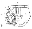
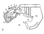
- a hook coupling according to the invention generally designated 10. It comprises a hook body 12 with a hooking opening 14 (see Fig. 4 and 5 ) And with a pivotally hinged on the hook body closure pawl 16. More precisely, the closure pawl 16 is pivotable about a closure pawl pivot axis 18 on the hook body 12 is provided.
- the hook body 12 and closure pawl 16 define a passage opening 22 in which a drawbar eye of a trailing vehicle can be accommodated.
- a locking lever 26 is pivoted about a locking lever pivot axis 24 parallel to the locking pawl pivot axis 18.
- the locking lever 26 is in its blocking position, that is, a front-side stop surface 28 is in contact with a counter-abutment surface 30 of the hook body.
- the closure flap 16 can not escape its position in FIG Fig. 2 shown closure position to be pivoted clockwise.
- the locking lever 26 is by a compression spring 32, which is stretched between the locking pawl 16 and a clamping extension 34 of the locking lever 26, in the in Fig. 2 biased locked position shown.
- the compression spring 32 is only in Fig. 2 represented and in the Fig. 3 to 5 omitted.
- the hook coupling 10 comprises a triggering device 36 pivotable about the pivot axis 18 on the hook body 12.
- This comprises a lever-like triggering component 38 Fig. 2 is the trigger member 38 shown in its normal position in which it inhibits movement of the locking lever 26 from its blocking position.
- the triggering component 38 in a cover part 40 on a locking portion 42 which is arranged in juxtaposition to a locking counter portion 44 of the locking lever 26.
- the locking counterpart portion 44 is replicated following an envelope at a distance, which is generated by the locking portion 44 upon pivoting of the triggering member 38 from the basic position to the release position.
- the triggering device 36 handles 46, which protrude in the lateral direction.
- a tension spring 48 in the in Fig. 2 biased basic position shown biased.
- the tension spring is set triggering component side on a the triggering member 38 passing through rod 50 and is fixed with its other longitudinal end to a catch ratchet fixed spring abutment 52.
- the tension spring 48 is for clarity only in the Fig. 2 represented and in the Fig. 3 to 5 omitted.
- depressions 54 are provided on the side legs 16 a and 16 b of the closure pawl (see in particular Fig. 3 to 5 ).
- the locking lever pivot near the longitudinal end of the locking lever 26 is formed as a sub-cylinder, wherein the cylinder axis of the sub-cylinder coincides with the locking lever pivot axis 24.
- a partially cylindrical recess 58 is formed with a small gap distance from the part-cylindrical formation 56 of the locking lever 26, which surrounds the teilzylindwitz training 56 of the locking lever 26 through an angle of about 170 °.
- the gap between the part-cylindrical formation 56 of the locking lever 26 and the part-cylindrical recess 58 in the closure pawl is between about 0.5 and 2.5 mm.
- the partially cylindrical recess 58 of the locking pawl 16 holds the locking lever 26 approximately in its in Fig. 2 Shown blocking position, so that even with a broken pivot axis or pivot shaft of the locking lever 26, the desired locking action of the locking lever 26 is maintained.
- the locking lever 26 is further pivoted by the Schmidtstromeingriff the rod 50 on the contact contour 60 in a counterclockwise direction until it is against a mechanical stop 62 (see Fig. 4 ) arrives at the lock pawl 16.
- the closure pawl 16 of the locking lever 26 and the trigger member 38 are braced against each other in a further pivotal movement of the trigger member 38 in a clockwise direction such that a pivoting movement of the trigger member 38 in a clockwise direction to a pivotal movement of the latch 16 in a clockwise direction leads (see Fig. 4 ), so that the hooking opening 14 is gradually released.
- Fig. 5 the closure pawl 16 is shown in its open position, wherein a contact portion 64 of the closure pawl 16 abuts against the abutment surface 30 of the hook body 12 so that a towing eye for coupling to the hook body 12 can not reach the counter stop surface 30 and damage it.
- the locking lever 26 is latched with a latching recess 66 on a latching counter-geometry 68 of the hook body under the action of the compression spring 32 surmountable.
- the closure pawl 16 by pressing in the counterclockwise direction, releasing the surmountable locking between locking lever 26 and hook body 12 back into the in Fig. 2 Shutter position shown to be moved. Due to the bias voltages of the individual components shown above, the locking pawl 16 automatically locks in its closed position against reopening.
- the opening operation of the pawl 16 can, as explained above, be carried out with one hand.
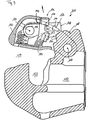
- a comparative example of a hook coupling is shown.
- the same or functionally identical components of the comparative example are denoted by the same reference numerals as corresponding components of the first embodiment, but increased by the number 100.
- the comparative example will be described below only insofar as it undercuts the first embodiment.
- the triggering component 138 in the comparative example is pivotably connected to the closure pawl 116 about a triggering component pivot axis 119.
- the trigger member 136 is not in the clockwise direction as in the first embodiment, but in the counterclockwise direction from the in Fig. 6 shown basic position in a locking lever 126 for movement from the locking position releasing release position movable.
- the trigger member 138 is connected by a torsion spring 148 in the in Fig. 6 biased basic position shown biased.
- One end leg of the torsion spring 148 rests on a rigidly connected to the trigger member 136 plastic buffer 151, while another, opposite end leg of the torsion spring 148 is supported on the lock pawl 116.
- the plastic buffer 151 has a bead 153, which serves as a driver device and, as in the first embodiment, in the basic position of the trigger member 138 spaced from a contact contour 160 of the locking lever 126, upon pivoting of the trigger member 138 from the normal position on the release position addition However, in abutting engagement with the system contour 160 passes, and thus pivots the locking lever 126 with continued pivotal movement of the trigger member 138 in the counterclockwise direction from the blocking position in the direction of the release position.
- a cover part 140 of the release component 138 is formed with a step to the pivot axis 119 of the release member 138 back.
- a free longitudinal end of the lid part 140 is formed as an extended cover, which is to prevent dirt entering the lock pawl.
- a step formation 145 interacting with the radial step of the cover part 140 is formed, which ensures that the pivot lever 126 can not be pivoted counterclockwise out of the locked position until the radial step of the cover part 140 the step formation 145 of the locking lever 126 has passed.
- the locking portion 142 of the release member 138 is hook-shaped, wherein the engagement surface 142 a of the locking portion 142 is a part-cylindrical peripheral surface with the release member pivot axis 119 as the central axis.
- the latch 116 can simply be moved clockwise from the closed position to the open position (see FIG Fig. 9 and 10 ).
- the basic position for the respective triggering component can only be achieved when the locking lever is in the blocking position.
Landscapes
- Engineering & Computer Science (AREA)
- General Engineering & Computer Science (AREA)
- Mechanical Engineering (AREA)
- Transportation (AREA)
- Lock And Its Accessories (AREA)
- Hooks, Suction Cups, And Attachment By Adhesive Means (AREA)
- Mechanical Operated Clutches (AREA)
- Vending Machines For Individual Products (AREA)
- Sewing Machines And Sewing (AREA)
- Invalid Beds And Related Equipment (AREA)
- Cookers (AREA)
Claims (16)
- Couplage par crochet avec un corps de crochet (12) présentant une ouverture d'accrochage (14) et un cliquet de fermeture (16) qui peut être réglé entre une position ouverte, dans laquelle l'ouverture d'accrochage (14) est ouverte au moins jusqu'à ce qu'un anneau d'attelage puisse être accroché au corps de crochet (12) pour l'établissement d'une liaison positive avec celui-ci, et une position de fermeture, dans laquelle l'ouverture d'accrochage (14) est bloquée au moins jusqu'à ce qu'un anneau d'attelage accroché au corps de crochet (12) soit bloqué pour rester sur celui-ci, le couplage par crochet (10) comprenant en outre :un levier d'arrêt (26) qui peut être pivoté entre une position de blocage, dans laquelle il bloque un réglage du cliquet de fermeture (16) de la position de fermeture à la position ouverte, et une position de libération, dans laquelle il autorise un réglage du cliquet de fermeture (16) de la position de fermeture à la position ouverte, ainsi queun dispositif de déclenchement (36) qui bloque dans sa position de base si le levier d'arrêt (26) se trouve dans la position de blocage, un déplacement du levier d'arrêt (26) dans la position de libération et qui permet en cas d'actionnement depuis sa position de base, un déplacement du levier d'arrêt (26) dans la position de libération,le dispositif de déclenchement (36) présentant un composant de déclenchement (38) logé de manière mobile sur le cliquet de fermeture (16) ou de préférence sur le corps de crochet (12) ou sur un composant relié de manière rigide au corps de crochet (12) ou cliquet de fermeture (16), qui est mobile entre la position de base et une position de déclenchement, dans laquelle il permet le déplacement du levier d'arrêt (26) dans la position de libération, le composant de déclenchement (38) étant prévu de manière pivotante entre la position de base et la position de déclenchement sur le cliquet de fermeture (16) ou de préférence sur le corps de crochet (12),caractérisé en ce que le levier d'arrêt (26) et le composant de déclenchement (38) peuvent être pivotés en sens inverse.
- Couplage par crochet selon la revendication 1,
caractérisé en ce que le composant de déclenchement (38) est précontraint sous l'effet de la force dans la position de base. - Couplage par crochet selon la revendication 2,
caractérisé en ce qu'il comporte au moins un ressort de précontrainte de composant de déclenchement (48) qui est appuyé au niveau d'une extrémité contre le composant de déclenchement (38) et au niveau de l'autre extrémité contre l'un des composants suivants, le levier d'arrêt (26), le corps de crochet (12) ou le cliquet de fermeture (16), de préférence contre le cliquet de fermeture (16). - Couplage par crochet selon l'une quelconque des revendications précédentes,
caractérisé en ce que le composant de déclenchement (38) présente une section de verrouillage (42) qui est disposée dans la position de base du composant de déclenchement (38) en parallèle ou en appui contre une section antagoniste de verrouillage (44) du levier d'arrêt (26). - Couplage par crochet selon la revendication 4,
caractérisé en ce que dans la position de déclenchement, la section de verrouillage (42) est éloignée de la section antagoniste de verrouillage (44). - Couplage par crochet selon la revendication 4 ou 5,
caractérisé en ce que dans la position de base du composant de déclenchement (38), le levier d'arrêt (26) et le composant de déclenchement (38) sont bloqués automatiquement de telle manière qu'un déplacement du levier d'arrêt (26) de la position de blocage à la position de libération ne provoque aucun déplacement du composant de déclenchement (38) de la position de base à la position de déclenchement. - Couplage par crochet selon l'une quelconque des revendications précédentes,
caractérisé en ce que le levier d'arrêt (26) est réalisé sur son extrémité longitudinale plus proche de l'axe de pivotement du levier d'arrêt de manière partiellement symétrique en rotation par rapport à l'axe de pivotement du levier d'arrêt (24) et cette extrémité longitudinale est entourée par un évidement (58) essentiellement complémentaire dans le composant logeant le levier d'arrêt au-delà d'une plage angulaire prédéterminée, comprise de préférence environ entre 140 et 180°. - Couplage par crochet selon l'une quelconque des revendications précédentes,
caractérisé en ce que le composant de déclenchement (38) présente un dispositif d'entraînement (50) qui entraîne le levier d'arrêt (26) de la position de blocage en direction de la position de libération, au moins pendant une section d'un mouvement de pivotement du composant de déclenchement (38) de la position de base. - Couplage par crochet selon la revendication 8,
caractérisé en ce que le levier d'arrêt (26) peut être déplacé par le composant de déclenchement (28) au moyen du dispositif d'entraînement (50) de la position de blocage à la position de libération. - Couplage par crochet selon la revendication 8 ou 9 en intégrant la revendication 3,
caractérisé en ce que le dispositif d'entraînement (50) sert d'appui au ressort de précontrainte côté composant de déclenchement. - Couplage par crochet selon l'une quelconque des revendications 8 à 10,
caractérisé en ce que le dispositif d'entraînement (50) présente une surface de glissement qui parvient en engagement d'appui glissant sur un contour d'appui (60) du levier d'arrêt (26) au moins pendant une section du mouvement de pivotement du composant de déclenchement (38) de la position de base à la position de déclenchement. - Couplage par crochet selon l'une quelconque des revendications précédentes,
caractérisé en ce que le cliquet de fermeture (16) est prévu de manière à pouvoir pivoter, le cliquet de fermeture (16) et le composant de déclenchement (38) pouvant être pivotés autour d'un axe de pivotement commun (18). - Couplage par crochet selon l'une quelconque des revendications précédentes,
caractérisé en ce que le levier d'arrêt (26) est précontraint vers la position de blocage. - Couplage par crochet selon l'une quelconque des revendications précédentes,
caractérisé en ce que le levier d'arrêt (26) est logé de manière mobile dans le cliquet de fermeture (16) entre la position de blocage et la position de libération. - Couplage par crochet selon l'une quelconque des revendications précédentes,
caractérisé en ce que le cliquet de fermeture (16) comporte une butée mécanique (62) qui limite la zone de déplacement du levier d'arrêt (26) près de la position de libération contre tout déplacement de la position de blocage. - Couplage par crochet selon l'une quelconque des revendications précédentes,
caractérisé en ce qu'une surface de butée antagoniste (30) du corps de crochet (12), avec laquelle une surface de butée (28) du levier d'arrêt (26) parvient en engagement d'appui dans sa position de blocage, est réalisée aussi pour l'appui d'une section d'appui (64) du cliquet de fermeture (16) dessus et ce de telle manière que la surface de butée antagoniste (30) limite la possibilité de réglage du cliquet de fermeture (16) près de la position ouverte en direction de la position de fermeture.
Applications Claiming Priority (2)
| Application Number | Priority Date | Filing Date | Title |
|---|---|---|---|
| DE102007038142A DE102007038142A1 (de) | 2007-08-13 | 2007-08-13 | Hakenkupplung |
| PCT/EP2008/006611 WO2009021709A1 (fr) | 2007-08-13 | 2008-08-11 | Couplage par crochet |
Publications (2)
| Publication Number | Publication Date |
|---|---|
| EP2185372A1 EP2185372A1 (fr) | 2010-05-19 |
| EP2185372B1 true EP2185372B1 (fr) | 2011-03-02 |
Family
ID=39739617
Family Applications (1)
| Application Number | Title | Priority Date | Filing Date |
|---|---|---|---|
| EP08785491A Not-in-force EP2185372B1 (fr) | 2007-08-13 | 2008-08-11 | Couplage par crochet |
Country Status (8)
| Country | Link |
|---|---|
| US (1) | US8684391B2 (fr) |
| EP (1) | EP2185372B1 (fr) |
| AT (1) | ATE500076T1 (fr) |
| AU (1) | AU2008286362A1 (fr) |
| DE (2) | DE102007038142A1 (fr) |
| RU (1) | RU2438881C2 (fr) |
| WO (1) | WO2009021709A1 (fr) |
| ZA (1) | ZA201001098B (fr) |
Families Citing this family (5)
| Publication number | Priority date | Publication date | Assignee | Title |
|---|---|---|---|---|
| US11186129B1 (en) * | 2018-05-11 | 2021-11-30 | Premier Equipment, Inc. | Towing coupler |
| US11318801B1 (en) * | 2018-05-11 | 2022-05-03 | Premier Equipment, Inc. | Towing coupler with coupler closer |
| US10933706B2 (en) * | 2018-12-04 | 2021-03-02 | Ford Global Technologies, Llc | Vehicle tow hook |
| RU190000U1 (ru) * | 2019-02-11 | 2019-06-14 | Публичное акционерное общество "КАМАЗ" | Тягово-сцепное устройство транспортного средства |
| US11577559B2 (en) | 2020-06-03 | 2023-02-14 | Ford Global Technologies, Llc | Vehicle tow hook |
Family Cites Families (12)
| Publication number | Priority date | Publication date | Assignee | Title |
|---|---|---|---|---|
| US2426532A (en) | 1944-08-03 | 1947-08-26 | Atwood Vacuum Machine Co | Pintle hook for coupling devices |
| US2766995A (en) * | 1953-06-09 | 1956-10-16 | Dewey S Weiss | Positive lock trailer hitch |
| DE1717113U (de) | 1955-11-22 | 1956-02-16 | Ade Werk G M B H | Sicherheitsklinke an anhaengerkupplungen. |
| US2842380A (en) | 1956-04-16 | 1958-07-08 | Dewey S Weiss | Double lock trailer coupling |
| FR1527021A (fr) | 1967-03-30 | 1968-05-31 | Cie Francaise John Deere | Dispositif pour accoupler des remorques ou des outils à un véhicule tracteur |
| US3475037A (en) | 1967-07-31 | 1969-10-28 | Dewey S Weiss | Double lock trailer coupling |
| AT338021B (de) * | 1975-03-11 | 1977-07-25 | Walterscheid Gmbh Jean | Kupplungshaken, insbesondere fur ein dreipunktgestange eines schleppers |
| US4758015A (en) | 1985-03-20 | 1988-07-19 | Eagle Manufacturing Company | Latch mechanism for hitch assembly |
| US4721324A (en) | 1987-02-19 | 1988-01-26 | William Blacklaw | Locking mechanism for trailer coupling |
| US4958848A (en) * | 1989-05-01 | 1990-09-25 | Nash Boyd B | Pintle type trailer coupling |
| US5033764A (en) | 1990-06-04 | 1991-07-23 | William Blacklaw | Locking trailer coupling |
| US7431321B2 (en) | 2003-05-28 | 2008-10-07 | Saf-Holland, Inc. | Trailer hitch assembly |
-
2007
- 2007-08-13 DE DE102007038142A patent/DE102007038142A1/de not_active Withdrawn
-
2008
- 2008-08-11 AT AT08785491T patent/ATE500076T1/de active
- 2008-08-11 RU RU2010109389/11A patent/RU2438881C2/ru not_active IP Right Cessation
- 2008-08-11 AU AU2008286362A patent/AU2008286362A1/en not_active Abandoned
- 2008-08-11 DE DE502008002755T patent/DE502008002755D1/de active Active
- 2008-08-11 WO PCT/EP2008/006611 patent/WO2009021709A1/fr not_active Ceased
- 2008-08-11 EP EP08785491A patent/EP2185372B1/fr not_active Not-in-force
- 2008-08-11 US US12/673,373 patent/US8684391B2/en active Active
-
2010
- 2010-02-16 ZA ZA201001098A patent/ZA201001098B/xx unknown
Also Published As
| Publication number | Publication date |
|---|---|
| ZA201001098B (en) | 2010-10-27 |
| US8684391B2 (en) | 2014-04-01 |
| DE102007038142A1 (de) | 2009-02-19 |
| US20110209310A1 (en) | 2011-09-01 |
| RU2010109389A (ru) | 2011-09-20 |
| DE502008002755D1 (de) | 2011-04-14 |
| EP2185372A1 (fr) | 2010-05-19 |
| RU2438881C2 (ru) | 2012-01-10 |
| ATE500076T1 (de) | 2011-03-15 |
| AU2008286362A1 (en) | 2009-02-19 |
| WO2009021709A1 (fr) | 2009-02-19 |
Similar Documents
| Publication | Publication Date | Title |
|---|---|---|
| DE602005000040T2 (de) | Vorrichtung zum Anheben einer Motorhaube mit einem Haken als Verriegelungssystem | |
| DE4321586C2 (de) | Motorbetriebene Schließvorrichtung | |
| EP2655126B1 (fr) | Verrou pour siège de véhicule et siège de véhicule | |
| AT510436B1 (de) | Karabinerhaken | |
| EP2325419A9 (fr) | Poignée de porte de sécurité | |
| DE3815890A1 (de) | Fernbetaetigter riegelmechanismus | |
| DE10312304A1 (de) | Kraftffahrzeugschloß | |
| EP2185372B1 (fr) | Couplage par crochet | |
| DE2415948A1 (de) | Schnappverriegelung fuer tueren und aehnliche schwenkbare oder gleitbare bauteile | |
| DE102015122575A1 (de) | Sicherheitsvorrichtung für ein Kraftfahrzeug mit einer Drehfalle und einer Vorraststellung und einer Hauptraststellung | |
| EP2843168B1 (fr) | Serrure de véhicule automobile | |
| DE3925513A1 (de) | Antriebsvorrichtung fuer einen ueberrollbuegel eines kraftfahrzeugs | |
| EP2248966A1 (fr) | Serrure de porte dotée d'un élément de fermeture et entraînement d'élément de fermeture commutable | |
| DE1653994B2 (de) | Kraftfahrzeugtürverschluß | |
| EP1970508A2 (fr) | Dispositif de blocage d'un élément pivotant d'un véhicule automobile | |
| DE102013112124A1 (de) | Lenkradschloss für eine Lenksäule für ein Kraftfahrzeug | |
| EP3122968B1 (fr) | Serrure à loqueteau avec protection contre les manipulations par actionnement de loquet auxiliaire | |
| EP1538287B1 (fr) | Poignée extérieure de porte | |
| EP1420100A2 (fr) | Dispositif de verrouillage de porte, en particulier pour la porte d'une machine de traitement du linge | |
| DE69906647T2 (de) | Anhängerkupplung mit Schloss | |
| WO2020212070A1 (fr) | Dispositif d'ouverture d'élément en forme d'ailette, ainsi que véhicule | |
| EP3192956A1 (fr) | Positionneur de couvercle | |
| EP1418385A2 (fr) | Dispositif de verrouillage de porte pour four de cuisson | |
| DE102006002850A1 (de) | Kraftfahrzeugschloß | |
| DE102019124646B4 (de) | Verriegelungseinrichtung |
Legal Events
| Date | Code | Title | Description |
|---|---|---|---|
| PUAI | Public reference made under article 153(3) epc to a published international application that has entered the european phase |
Free format text: ORIGINAL CODE: 0009012 |
|
| 17P | Request for examination filed |
Effective date: 20100312 |
|
| AK | Designated contracting states |
Kind code of ref document: A1 Designated state(s): AT BE BG CH CY CZ DE DK EE ES FI FR GB GR HR HU IE IS IT LI LT LU LV MC MT NL NO PL PT RO SE SI SK TR |
|
| AX | Request for extension of the european patent |
Extension state: AL BA MK RS |
|
| GRAP | Despatch of communication of intention to grant a patent |
Free format text: ORIGINAL CODE: EPIDOSNIGR1 |
|
| DAX | Request for extension of the european patent (deleted) | ||
| GRAA | (expected) grant |
Free format text: ORIGINAL CODE: 0009210 |
|
| GRAS | Grant fee paid |
Free format text: ORIGINAL CODE: EPIDOSNIGR3 |
|
| AK | Designated contracting states |
Kind code of ref document: B1 Designated state(s): AT BE BG CH CY CZ DE DK EE ES FI FR GB GR HR HU IE IS IT LI LT LU LV MC MT NL NO PL PT RO SE SI SK TR |
|
| REG | Reference to a national code |
Ref country code: GB Ref legal event code: FG4D Free format text: NOT ENGLISH |
|
| REG | Reference to a national code |
Ref country code: CH Ref legal event code: NV Representative=s name: BOHEST AG Ref country code: CH Ref legal event code: EP |
|
| REG | Reference to a national code |
Ref country code: IE Ref legal event code: FG4D Free format text: LANGUAGE OF EP DOCUMENT: GERMAN |
|
| REF | Corresponds to: |
Ref document number: 502008002755 Country of ref document: DE Date of ref document: 20110414 Kind code of ref document: P |
|
| REG | Reference to a national code |
Ref country code: DE Ref legal event code: R096 Ref document number: 502008002755 Country of ref document: DE Effective date: 20110414 |
|
| REG | Reference to a national code |
Ref country code: SE Ref legal event code: TRGR |
|
| REG | Reference to a national code |
Ref country code: NL Ref legal event code: VDEP Effective date: 20110302 |
|
| PG25 | Lapsed in a contracting state [announced via postgrant information from national office to epo] |
Ref country code: GR Free format text: LAPSE BECAUSE OF FAILURE TO SUBMIT A TRANSLATION OF THE DESCRIPTION OR TO PAY THE FEE WITHIN THE PRESCRIBED TIME-LIMIT Effective date: 20110603 Ref country code: LV Free format text: LAPSE BECAUSE OF FAILURE TO SUBMIT A TRANSLATION OF THE DESCRIPTION OR TO PAY THE FEE WITHIN THE PRESCRIBED TIME-LIMIT Effective date: 20110302 Ref country code: HR Free format text: LAPSE BECAUSE OF FAILURE TO SUBMIT A TRANSLATION OF THE DESCRIPTION OR TO PAY THE FEE WITHIN THE PRESCRIBED TIME-LIMIT Effective date: 20110302 Ref country code: ES Free format text: LAPSE BECAUSE OF FAILURE TO SUBMIT A TRANSLATION OF THE DESCRIPTION OR TO PAY THE FEE WITHIN THE PRESCRIBED TIME-LIMIT Effective date: 20110613 Ref country code: NO Free format text: LAPSE BECAUSE OF FAILURE TO SUBMIT A TRANSLATION OF THE DESCRIPTION OR TO PAY THE FEE WITHIN THE PRESCRIBED TIME-LIMIT Effective date: 20110602 |
|
| PG25 | Lapsed in a contracting state [announced via postgrant information from national office to epo] |
Ref country code: CY Free format text: LAPSE BECAUSE OF FAILURE TO SUBMIT A TRANSLATION OF THE DESCRIPTION OR TO PAY THE FEE WITHIN THE PRESCRIBED TIME-LIMIT Effective date: 20110302 Ref country code: NL Free format text: LAPSE BECAUSE OF FAILURE TO SUBMIT A TRANSLATION OF THE DESCRIPTION OR TO PAY THE FEE WITHIN THE PRESCRIBED TIME-LIMIT Effective date: 20110302 Ref country code: SI Free format text: LAPSE BECAUSE OF FAILURE TO SUBMIT A TRANSLATION OF THE DESCRIPTION OR TO PAY THE FEE WITHIN THE PRESCRIBED TIME-LIMIT Effective date: 20110302 Ref country code: BG Free format text: LAPSE BECAUSE OF FAILURE TO SUBMIT A TRANSLATION OF THE DESCRIPTION OR TO PAY THE FEE WITHIN THE PRESCRIBED TIME-LIMIT Effective date: 20110602 |
|
| REG | Reference to a national code |
Ref country code: IE Ref legal event code: FD4D |
|
| PG25 | Lapsed in a contracting state [announced via postgrant information from national office to epo] |
Ref country code: EE Free format text: LAPSE BECAUSE OF FAILURE TO SUBMIT A TRANSLATION OF THE DESCRIPTION OR TO PAY THE FEE WITHIN THE PRESCRIBED TIME-LIMIT Effective date: 20110302 Ref country code: IE Free format text: LAPSE BECAUSE OF FAILURE TO SUBMIT A TRANSLATION OF THE DESCRIPTION OR TO PAY THE FEE WITHIN THE PRESCRIBED TIME-LIMIT Effective date: 20110302 Ref country code: PT Free format text: LAPSE BECAUSE OF FAILURE TO SUBMIT A TRANSLATION OF THE DESCRIPTION OR TO PAY THE FEE WITHIN THE PRESCRIBED TIME-LIMIT Effective date: 20110704 |
|
| PG25 | Lapsed in a contracting state [announced via postgrant information from national office to epo] |
Ref country code: RO Free format text: LAPSE BECAUSE OF FAILURE TO SUBMIT A TRANSLATION OF THE DESCRIPTION OR TO PAY THE FEE WITHIN THE PRESCRIBED TIME-LIMIT Effective date: 20110302 Ref country code: IS Free format text: LAPSE BECAUSE OF FAILURE TO SUBMIT A TRANSLATION OF THE DESCRIPTION OR TO PAY THE FEE WITHIN THE PRESCRIBED TIME-LIMIT Effective date: 20110702 Ref country code: CZ Free format text: LAPSE BECAUSE OF FAILURE TO SUBMIT A TRANSLATION OF THE DESCRIPTION OR TO PAY THE FEE WITHIN THE PRESCRIBED TIME-LIMIT Effective date: 20110302 Ref country code: SK Free format text: LAPSE BECAUSE OF FAILURE TO SUBMIT A TRANSLATION OF THE DESCRIPTION OR TO PAY THE FEE WITHIN THE PRESCRIBED TIME-LIMIT Effective date: 20110302 |
|
| PG25 | Lapsed in a contracting state [announced via postgrant information from national office to epo] |
Ref country code: MT Free format text: LAPSE BECAUSE OF FAILURE TO SUBMIT A TRANSLATION OF THE DESCRIPTION OR TO PAY THE FEE WITHIN THE PRESCRIBED TIME-LIMIT Effective date: 20110302 |
|
| PLBE | No opposition filed within time limit |
Free format text: ORIGINAL CODE: 0009261 |
|
| STAA | Information on the status of an ep patent application or granted ep patent |
Free format text: STATUS: NO OPPOSITION FILED WITHIN TIME LIMIT |
|
| 26N | No opposition filed |
Effective date: 20111205 |
|
| BERE | Be: lapsed |
Owner name: JOST-WERKE G.M.B.H. Effective date: 20110831 |
|
| PG25 | Lapsed in a contracting state [announced via postgrant information from national office to epo] |
Ref country code: PL Free format text: LAPSE BECAUSE OF FAILURE TO SUBMIT A TRANSLATION OF THE DESCRIPTION OR TO PAY THE FEE WITHIN THE PRESCRIBED TIME-LIMIT Effective date: 20110302 Ref country code: DK Free format text: LAPSE BECAUSE OF FAILURE TO SUBMIT A TRANSLATION OF THE DESCRIPTION OR TO PAY THE FEE WITHIN THE PRESCRIBED TIME-LIMIT Effective date: 20110302 |
|
| REG | Reference to a national code |
Ref country code: DE Ref legal event code: R097 Ref document number: 502008002755 Country of ref document: DE Effective date: 20111205 |
|
| PG25 | Lapsed in a contracting state [announced via postgrant information from national office to epo] |
Ref country code: MC Free format text: LAPSE BECAUSE OF NON-PAYMENT OF DUE FEES Effective date: 20110831 |
|
| PG25 | Lapsed in a contracting state [announced via postgrant information from national office to epo] |
Ref country code: BE Free format text: LAPSE BECAUSE OF NON-PAYMENT OF DUE FEES Effective date: 20110831 |
|
| PG25 | Lapsed in a contracting state [announced via postgrant information from national office to epo] |
Ref country code: LU Free format text: LAPSE BECAUSE OF NON-PAYMENT OF DUE FEES Effective date: 20110811 |
|
| PG25 | Lapsed in a contracting state [announced via postgrant information from national office to epo] |
Ref country code: HU Free format text: LAPSE BECAUSE OF FAILURE TO SUBMIT A TRANSLATION OF THE DESCRIPTION OR TO PAY THE FEE WITHIN THE PRESCRIBED TIME-LIMIT Effective date: 20110302 |
|
| PGFP | Annual fee paid to national office [announced via postgrant information from national office to epo] |
Ref country code: TR Payment date: 20130725 Year of fee payment: 6 |
|
| REG | Reference to a national code |
Ref country code: CH Ref legal event code: PCAR Free format text: NEW ADDRESS: HOLBEINSTRASSE 36-38, 4051 BASEL (CH) |
|
| PGFP | Annual fee paid to national office [announced via postgrant information from national office to epo] |
Ref country code: FI Payment date: 20140821 Year of fee payment: 7 Ref country code: LT Payment date: 20140811 Year of fee payment: 7 |
|
| PGFP | Annual fee paid to national office [announced via postgrant information from national office to epo] |
Ref country code: GB Payment date: 20140820 Year of fee payment: 7 Ref country code: AT Payment date: 20140821 Year of fee payment: 7 |
|
| REG | Reference to a national code |
Ref country code: DE Ref legal event code: R082 Ref document number: 502008002755 Country of ref document: DE Representative=s name: RUTTENSPERGER LACHNIT TROSSIN GOMOLL PATENT- U, DE Ref country code: DE Ref legal event code: R082 Ref document number: 502008002755 Country of ref document: DE Representative=s name: RUTTENSPERGER LACHNIT TROSSIN GOMOLL, PATENT- , DE |
|
| REG | Reference to a national code |
Ref country code: LT Ref legal event code: MM4D Effective date: 20150811 |
|
| REG | Reference to a national code |
Ref country code: AT Ref legal event code: MM01 Ref document number: 500076 Country of ref document: AT Kind code of ref document: T Effective date: 20150811 |
|
| GBPC | Gb: european patent ceased through non-payment of renewal fee |
Effective date: 20150811 |
|
| PG25 | Lapsed in a contracting state [announced via postgrant information from national office to epo] |
Ref country code: LT Free format text: LAPSE BECAUSE OF NON-PAYMENT OF DUE FEES Effective date: 20150811 |
|
| PG25 | Lapsed in a contracting state [announced via postgrant information from national office to epo] |
Ref country code: FI Free format text: LAPSE BECAUSE OF NON-PAYMENT OF DUE FEES Effective date: 20150811 Ref country code: AT Free format text: LAPSE BECAUSE OF NON-PAYMENT OF DUE FEES Effective date: 20150811 |
|
| PG25 | Lapsed in a contracting state [announced via postgrant information from national office to epo] |
Ref country code: GB Free format text: LAPSE BECAUSE OF NON-PAYMENT OF DUE FEES Effective date: 20150811 |
|
| REG | Reference to a national code |
Ref country code: FR Ref legal event code: PLFP Year of fee payment: 9 |
|
| REG | Reference to a national code |
Ref country code: FR Ref legal event code: PLFP Year of fee payment: 10 |
|
| PG25 | Lapsed in a contracting state [announced via postgrant information from national office to epo] |
Ref country code: TR Free format text: LAPSE BECAUSE OF NON-PAYMENT OF DUE FEES Effective date: 20150811 |
|
| PGFP | Annual fee paid to national office [announced via postgrant information from national office to epo] |
Ref country code: LU Payment date: 20170808 Year of fee payment: 14 Ref country code: CH Payment date: 20170817 Year of fee payment: 10 Ref country code: IT Payment date: 20170831 Year of fee payment: 10 |
|
| REG | Reference to a national code |
Ref country code: CH Ref legal event code: PL |
|
| PG25 | Lapsed in a contracting state [announced via postgrant information from national office to epo] |
Ref country code: LI Free format text: LAPSE BECAUSE OF NON-PAYMENT OF DUE FEES Effective date: 20180831 Ref country code: CH Free format text: LAPSE BECAUSE OF NON-PAYMENT OF DUE FEES Effective date: 20180831 |
|
| PG25 | Lapsed in a contracting state [announced via postgrant information from national office to epo] |
Ref country code: IT Free format text: LAPSE BECAUSE OF NON-PAYMENT OF DUE FEES Effective date: 20180811 |
|
| PG25 | Lapsed in a contracting state [announced via postgrant information from national office to epo] |
Ref country code: FR Free format text: LAPSE BECAUSE OF NON-PAYMENT OF DUE FEES Effective date: 20180831 |
|
| PGFP | Annual fee paid to national office [announced via postgrant information from national office to epo] |
Ref country code: SE Payment date: 20190826 Year of fee payment: 12 Ref country code: DE Payment date: 20190903 Year of fee payment: 12 |
|
| REG | Reference to a national code |
Ref country code: DE Ref legal event code: R119 Ref document number: 502008002755 Country of ref document: DE |
|
| REG | Reference to a national code |
Ref country code: SE Ref legal event code: EUG |
|
| PG25 | Lapsed in a contracting state [announced via postgrant information from national office to epo] |
Ref country code: SE Free format text: LAPSE BECAUSE OF NON-PAYMENT OF DUE FEES Effective date: 20200812 |
|
| PG25 | Lapsed in a contracting state [announced via postgrant information from national office to epo] |
Ref country code: DE Free format text: LAPSE BECAUSE OF NON-PAYMENT OF DUE FEES Effective date: 20210302 |