EP2186569A2 - Moulin de biomasse - Google Patents
Moulin de biomasse Download PDFInfo
- Publication number
- EP2186569A2 EP2186569A2 EP09013941A EP09013941A EP2186569A2 EP 2186569 A2 EP2186569 A2 EP 2186569A2 EP 09013941 A EP09013941 A EP 09013941A EP 09013941 A EP09013941 A EP 09013941A EP 2186569 A2 EP2186569 A2 EP 2186569A2
- Authority
- EP
- European Patent Office
- Prior art keywords
- biomass
- wooden
- pulverizing
- outer peripheral
- pulverized
- Prior art date
- Legal status (The legal status is an assumption and is not a legal conclusion. Google has not performed a legal analysis and makes no representation as to the accuracy of the status listed.)
- Granted
Links
- 239000002028 Biomass Substances 0.000 title claims abstract description 76
- 238000010298 pulverizing process Methods 0.000 claims abstract description 62
- 230000002093 peripheral effect Effects 0.000 claims abstract description 47
- 238000007664 blowing Methods 0.000 claims abstract description 8
- 239000000843 powder Substances 0.000 claims description 16
- 239000002245 particle Substances 0.000 claims description 5
- 239000003245 coal Substances 0.000 description 43
- 239000008188 pellet Substances 0.000 description 5
- 239000000446 fuel Substances 0.000 description 4
- 238000002485 combustion reaction Methods 0.000 description 2
- 239000000835 fiber Substances 0.000 description 2
- 230000005484 gravity Effects 0.000 description 2
- 238000004519 manufacturing process Methods 0.000 description 2
- 239000011802 pulverized particle Substances 0.000 description 2
- 230000001174 ascending effect Effects 0.000 description 1
- 230000003247 decreasing effect Effects 0.000 description 1
- 230000000694 effects Effects 0.000 description 1
- 229910052705 radium Inorganic materials 0.000 description 1
- HCWPIIXVSYCSAN-UHFFFAOYSA-N radium atom Chemical compound [Ra] HCWPIIXVSYCSAN-UHFFFAOYSA-N 0.000 description 1
- 239000004449 solid propellant Substances 0.000 description 1
Images


Classifications
-
- B—PERFORMING OPERATIONS; TRANSPORTING
- B02—CRUSHING, PULVERISING, OR DISINTEGRATING; PREPARATORY TREATMENT OF GRAIN FOR MILLING
- B02C—CRUSHING, PULVERISING, OR DISINTEGRATING IN GENERAL; MILLING GRAIN
- B02C15/00—Disintegrating by milling members in the form of rollers or balls co-operating with rings or discs
- B02C15/003—Shape or construction of discs or rings
-
- Y—GENERAL TAGGING OF NEW TECHNOLOGICAL DEVELOPMENTS; GENERAL TAGGING OF CROSS-SECTIONAL TECHNOLOGIES SPANNING OVER SEVERAL SECTIONS OF THE IPC; TECHNICAL SUBJECTS COVERED BY FORMER USPC CROSS-REFERENCE ART COLLECTIONS [XRACs] AND DIGESTS
- Y02—TECHNOLOGIES OR APPLICATIONS FOR MITIGATION OR ADAPTATION AGAINST CLIMATE CHANGE
- Y02E—REDUCTION OF GREENHOUSE GAS [GHG] EMISSIONS, RELATED TO ENERGY GENERATION, TRANSMISSION OR DISTRIBUTION
- Y02E50/00—Technologies for the production of fuel of non-fossil origin
- Y02E50/30—Fuel from waste, e.g. synthetic alcohol or diesel
Definitions
- the present invention relates to a biomass mill for pulverizing a wooden (ligneous) biomass such as wooden chips, wooden pallets, etc. to be used as a fuel for boilers.
- the wooden biomass When the wooden biomass is used as the fuel for boilers, the wooden biomass such as wooden chips, wooden pellets, etc. must be pulverized so that the wooden biomass will be combustible by burners.
- the wooden biomass When the wooden biomass is mixed in coal and is used as fuel, and if a mixing quantity of the wooden biomass is not much, it can be mixed and pulverized by using an existing type of coal mill. However, if the quantity of the wooden biomass used is increased, it is necessary to pulverize the wooden biomass by itself.
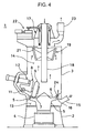
- a closed space is formed by a casing 3, which is erected on a base 2, and a pulverizing table 5 is mounted in a lower portion of the space via a table drive unit 4.
- the pulverizing table 5 is rotated at constant speed by the table drive unit 4.
- a table segment 7 is provided, which has a recessed groove 6 with a cross-section in arcuate form.
- the necessary sets, e.g. 3 sets, of pressure roller units 8 are arranged in radial direction from a rotation center of the pulverizing table 5.
- the pressure roller unit 8 has a pressure roller 9, which can be tilted freely with a horizontal support shaft 11 as a center.
- 3 sets of roller pressure devices 12 are disposed so that the roller pressure devices penetrate the casing 3 in radial direction.
- Each pressure roller 9 is pressed into the recessed groove 6 by the roller pressure device 12.
- a primary air chamber 13 is provided under the pulverizing table 5.
- a classifier chamber 14 is arranged above the pulverizing table 5 inside the casing 3.
- a primary air supply port 15 is mounted, and the primary air supply port 15 is communicated with the primary air chamber 13.
- a gap is formed, and the gap fulfills a function as a primary air blowout hole 16.
- a coal supply and discharge unit 17 is disposed in an upper part of the casing 3.
- a chute 18 in form of pipe is provided so that the chute 18 penetrates a central portion of the coal supply and discharge unit 17, and the chute 18 is extended to inner space of the casing 3.
- the coal is supplied to the chute 18, and the supplied coal is to fall down to the pulverizing table 5.
- a classifier 19 is rotatably mounted at the middle of the chute 18.
- the classifier 19 has a strip-type blade 21, which is disposed with a predetermined pitch in circumferential direction, and the classifier 19 is rotated by a rotary drive unit 22.
- a pulverized coal feeding pipe 23 for feeding the pulverized coal to the boiler burner is connected to the coal supply and discharge unit 17.
- the coal in form of lump is sent through the chute 18.
- the coal in form of lump fall toward a center of the pulverizing table 5 from a lower end of the chute 18, and the coal is supplied onto the pulverizing table 5.
- the coal on the pulverizing table 5 is moved in outer peripheral direction by centrifugal force.
- the coal is then caught by the pressure roller 9, is pulverized and is turned to powder state. Further, the coal is filled up in outer peripheral region by the centrifugal force from the table segment 7.
- the pulverized coal thus filled up is moved upward by the primary air, which is blown upward via the blowout hole 16.
- a dumb-ring 24 or an inner edge 26a is disposed in order to hold the coal on the table segment 7 for a required time period and to increase a pulverizing efficiency, and a coal layer with a thickness as required is formed on an upper surface of the table segment 7.
- wooden biomass such as wooden chips, wooden pellets, etc.
- wooden biomass When the wooden biomass such as wooden chips, wooden pellets, etc. (hereinafter referred as "wooden biomass”) is supplied to the vertical mill 1 or to a mill with an equivalent structure and is pulverized, it is found that the biomass exhibits behavior different from behavior of the coal described as follows, and that the pulverizing efficiency cannot be attained sufficiently.
- the coal has no caking property and has high specific gravity
- the coal is moved smoothly by the centrifugal force caused by the rotation of the pulverizing table 5, and the pulverizing efficiency as desired can be attained.
- sufficient pulverizing efficiency can be accomplished when a mixing ratio of the wooden biomass is 5% or less.
- the present invention provides a biomass mill, comprising a rotatable pulverizing table, a recessed groove which is provided in form of ring on an upper surface of the pulverizing table and has an arcuate cross-section, a pressure roller pressed into the recessed groove, a blowout hole for blowing out the air from around the pulverizing table, and a chute for supplying a wooden biomass toward a center of the pulverizing table, wherein the wooden biomass is supplied via the chute, the wooden biomass is pulverized between the pulverizing table and the pressure roller, and the pulverized wooden biomass is carried by blowing the air through the blowout hole, wherein a surface from an outer peripheral of the recessed groove to the blowout hole is flat surface.
- the present invention provides the biomass mill as described above, wherein at least an outer peripheral groove width angle of the recessed groove is set from 0° to 35° , and also provides the biomass mill as described above, wherein the outer peripheral groove width angle of the recessed groove is set to a value smaller than the inner peripheral groove width angle.
- the present invention provides a biomass mill, comprising a rotatable pulverizing table, a recessed groove which is provided in form of ring on an upper surface of the pulverizing table and has an arcuate cross-section, a pressure roller pressed into the recessed groove, a blowout hole for blowing out the air from around the pulverizing table, and a chute for supplying a wooden biomass toward a center of the pulverizing table, wherein the wooden biomass is supplied via the chute, the wooden biomass is pulverized between the pulverizing table and the pressure roller, and the pulverized wooden biomass is carried by blowing the air through the blowout hole, wherein a surface from an outer peripheral of the recessed groove to the blowout hole is flat surface.
- the wooden biomass is easily moved in outer peripheral direction, and the pulverizing capacity can be increased. Because the outer peripheral groove width angle of the recessed groove is designed smaller than the inner peripheral groove width angle, the wooden biomass is moved in outer peripheral direction more easily, and this contributes to the increase of the pulverizing capacity.
- An air port ring 26 is disposed on outer periphery of the table segment 7.
- a blowout hole 16 is formed on the air port ring 26 at a predetermined distance so that a primary air is blown upward via the blowout hole 16.
- An inner edge 26a of the air port ring 26 is designed so that an inner edge 26a of the air port ring 26 is tapered and inclined downward toward a center, and the inner edge 26a is inclined in approximately similar manner to a tangential line on an outer edge end of a recessed groove 6.
- the inner edge 26a is designed in such manner that a pulverized coal can be moved smoothly from the recessed groove 6 to the inner edge 26a.
- a dumb-ring 24 and the inner edge 26a are provided on an upper surface and on inner periphery of the air port ring 26, a dumb-ring 24 and the inner edge 26a are provided.
- the dumb-ring 24 is positioned between the outer peripheral edge of the inner edge 26a and the blowout hole 16.
- An inner peripheral surface of the dumb-ring 24 runs in vertical direction, and is a surface bent discontinuously with the inner edge 26a.
- reference numeral 27 denotes a layer of the pulverized coal where the coal is pulverized, and an arrow mark 28 indicates a flow of the pulverized coal layer 27.
- the dumb-ring 24 is disposed on a periphery of the table segment 7 so that the flow of the pulverized coal layer 27 is blocked and a thickness of the pulverized coal layer 27 is maintained. After passing beyond the dumb-ring 24 or the inner edge 26a, the pulverized coal is blown upward by the primary air blown via the blowout hole 16.
- the coal has no caking property and has high specific gravity.
- the pulverized coal layer 27 is moved smoothly by the centrifugal force caused by the rotation of the pulverizing table 5.
- the dumb-ring 24 or the inner edge 26a is needed, which can suppress the flow of the pulverized coal layer 27.
- the wooden biomass is made of light-weight fibers and the wooden biomass moves on the table not very smoothly compared with the coal. Accordingly, when the dumb-ring 24 or the inner edge 26a is disposed, the movement of the pulverizing table 5 is hindered more.
- biomass powder the powder (hereinafter referred as "biomass powder") is not easily discharged out of the mill. As a result, the pulverizing capacity is limited because of the increase of differential pressure within the mill and the increase of moving power of the table drive unit 4.
- pulverizing may be carried out to have the maximum particle size of less than 1 mm.
- the recessed groove 6 is designed symmetrically to a line, which runs perpendicularly to the center of the groove (left-to-right symmetry in the figure).
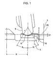
- a radius of curvature of the recessed groove 6 is set to "r” and angle of groove width (i.e. an angle from the centerline to a groove edge; hereinafter referred as "groove width angle") is ⁇ 2.
- groove width angle angle of groove width
- depth D2 of the recessed groove 6 is given as: (r - r cos ⁇ 2).
- the groove width angle ⁇ 2 is 40° or more.
- the dumb-ring 24 and the inner edge 26a are not used.
- a portion from outer peripheral edge of the recessed groove 6 to the blowout hole 16 is designed as a horizontal flat surface.
- a groove width angle on inner peripheral side from the center of the groove hereinafter referred as “inner peripheral groove width angle ⁇ 2”
- a groove width angle on outer peripheral side hereinafter referred as “outer peripheral groove width angle ⁇ 1”
- ⁇ ⁇ 2 45 ⁇ ° to 30 ⁇ °
- ⁇ ⁇ 1 35 ⁇ ° to 0 ⁇ ° .
- the flat surface may be horizontal or may be inclined upward to outside or may be inclined downward with respect to a horizontal plane. To design the flat surface horizontally or with ascending inclination or descending inclination, it is determined according to the pulverized condition of the wooden biomass or to the moving condition in radial direction.
- a depth D1 on outer peripheral side of the recessed groove 6 in the present embodiment is: (r - r cos ⁇ 1) ( ⁇ D2).
- the depth of the groove is shallower by an extent of h2.
- the depth of the groove is shallower by an extent of hl, i.e. shallower by the height of the inner edge 26a and the height of the dumb-ring 24.
- the depth of the groove on outer peripheral side is shallower by (hl + h2) than the prior art.
- the biomass powder is more easily moved toward outer peripheral side of the pulverizing table 5.
- the dumb-ring 24 is not used, a stagnation of the biomass powder in the recessed groove 6 can be eliminated, and the biomass powder moves more quickly toward outer peripheral side.
- the width of the recessed groove 6 is "2rsin ⁇ 2" in the prior art, while it is “rsin ⁇ 1 + rsin ⁇ 2" (where ⁇ 1 ⁇ ⁇ 2; rsin ⁇ 1 ⁇ rsin ⁇ 2).
- the region where pressure is applied by the pressure roller 9 will be smaller, and the pulverized particle diameter will be larger than the pulverized particle diameter in the past.
- the pulverizing capacity can be extensively increased.
- the turning radius (radium of gyration) R at the center of the recessed groove 6 is set to 675 mm, and the radius of curvature "r" of the recessed groove 6 is set to 189 mm.
- Fig. 3 shows the results of comparison between a case where a conventional type coal mill is used as a biomass mill and the wooden chips and the wooden pellets are pulverized by themselves and a case where the wooden chips and the wooden pellets are pulverized by a biomass mill according to the present embodiment.
Landscapes
- Engineering & Computer Science (AREA)
- Food Science & Technology (AREA)
- Crushing And Grinding (AREA)
- Solid Fuels And Fuel-Associated Substances (AREA)
Applications Claiming Priority (1)
| Application Number | Priority Date | Filing Date | Title |
|---|---|---|---|
| JP2008293770A JP5412801B2 (ja) | 2008-11-17 | 2008-11-17 | バイオマスミル |
Publications (3)
| Publication Number | Publication Date |
|---|---|
| EP2186569A2 true EP2186569A2 (fr) | 2010-05-19 |
| EP2186569A3 EP2186569A3 (fr) | 2010-07-07 |
| EP2186569B1 EP2186569B1 (fr) | 2012-03-14 |
Family
ID=41466829
Family Applications (1)
| Application Number | Title | Priority Date | Filing Date |
|---|---|---|---|
| EP09013941A Not-in-force EP2186569B1 (fr) | 2008-11-17 | 2009-11-06 | Broyeur à cylindres pour le broyage de matière biomasse |
Country Status (4)
| Country | Link |
|---|---|
| US (1) | US7926755B2 (fr) |
| EP (1) | EP2186569B1 (fr) |
| JP (1) | JP5412801B2 (fr) |
| AT (1) | ATE549086T1 (fr) |
Families Citing this family (2)
| Publication number | Priority date | Publication date | Assignee | Title |
|---|---|---|---|---|
| JP5496055B2 (ja) * | 2010-10-26 | 2014-05-21 | 三菱重工業株式会社 | バイオマスペレット粉砕装置及びバイオマス・石炭混焼システム |
| JP7282540B2 (ja) * | 2019-02-13 | 2023-05-29 | 三菱重工業株式会社 | 固体燃料粉砕装置及びこれを備えた発電プラント並びに固体燃料粉砕方法 |
Family Cites Families (14)
| Publication number | Priority date | Publication date | Assignee | Title |
|---|---|---|---|---|
| JPS5415348B2 (fr) * | 1975-01-28 | 1979-06-14 | ||
| JPS6049940U (ja) * | 1983-09-16 | 1985-04-08 | 宇部興産株式会社 | 竪型粉砕機 |
| US4606506A (en) * | 1984-05-04 | 1986-08-19 | Kawasaki Jukogyo Kabushiki Kaisha | Vertical type roller mill |
| JPS614548A (ja) * | 1984-06-16 | 1986-01-10 | 川崎重工業株式会社 | 竪型ミル |
| DE3822290A1 (de) * | 1988-07-01 | 1990-01-04 | Babcock Werke Ag | Walzenschuesselmuehle |
| JP2685820B2 (ja) * | 1988-07-14 | 1997-12-03 | バブコツク日立株式会社 | ローラ式粉砕装置 |
| CA1311232C (fr) * | 1989-07-20 | 1992-12-08 | Randall J. Novotny | Pulverisateur a table de broyage rotative avec segments d'arrivee d'air remplacables |
| JPH06210193A (ja) * | 1993-01-20 | 1994-08-02 | Sumitomo Metal Ind Ltd | 高炉水砕スラグ微粉化における粒鉄の回収方法と装置 |
| JPH11207200A (ja) | 1998-01-20 | 1999-08-03 | Mitsubishi Heavy Ind Ltd | 竪型ローラミルおよびその運転方法 |
| GB0002149D0 (en) * | 2000-02-01 | 2000-03-22 | Nat Power Plc | Flow improvement element in a flow directing means |
| JP2003071306A (ja) * | 2001-08-30 | 2003-03-11 | Kurimoto Ltd | 堅型粉砕機 |
| JP4379263B2 (ja) | 2003-09-17 | 2009-12-09 | 宇部興産株式会社 | 木質燃料製造方法 |
| GB2420992B (en) * | 2004-04-19 | 2008-05-21 | William Graham Bell | Industrial apparatus |
| JP4939145B2 (ja) * | 2006-08-21 | 2012-05-23 | 三菱重工業株式会社 | バイオマス粉砕装置およびその制御方法 |
-
2008
- 2008-11-17 JP JP2008293770A patent/JP5412801B2/ja active Active
-
2009
- 2009-11-06 AT AT09013941T patent/ATE549086T1/de active
- 2009-11-06 EP EP09013941A patent/EP2186569B1/fr not_active Not-in-force
- 2009-11-12 US US12/590,702 patent/US7926755B2/en not_active Expired - Fee Related
Also Published As
| Publication number | Publication date |
|---|---|
| EP2186569B1 (fr) | 2012-03-14 |
| JP2010119923A (ja) | 2010-06-03 |
| ATE549086T1 (de) | 2012-03-15 |
| JP5412801B2 (ja) | 2014-02-12 |
| EP2186569A3 (fr) | 2010-07-07 |
| US20100123033A1 (en) | 2010-05-20 |
| US7926755B2 (en) | 2011-04-19 |
Similar Documents
| Publication | Publication Date | Title |
|---|---|---|
| RU145376U1 (ru) | Центробежный дисковый измельчитель | |
| US10124373B2 (en) | Rotary classifier and vertical mill | |
| RU2011148952A (ru) | Перемешивающий ротор и перемешивающее устройство | |
| EP2186569B1 (fr) | Broyeur à cylindres pour le broyage de matière biomasse | |
| JP5030430B2 (ja) | 竪型ローラミル | |
| FI72891B (fi) | Tallrikskross. | |
| JP2012228636A (ja) | 竪型ミル | |
| US10882050B2 (en) | Rotary classifier and vertical mill | |
| JP2010149052A (ja) | 竪型ミル | |
| JP2019084476A (ja) | 粉砕機及び粉砕機の運転方法 | |
| CN205222144U (zh) | 落料装置 | |
| JP6024302B2 (ja) | 竪型粉砕機 | |
| CN118847258A (zh) | 一种破碎给料装置及分选机 | |
| JP5857629B2 (ja) | バイオマスミル | |
| CN112317028B (zh) | 一种应用于矿山开采的圆锥破碎机 | |
| JP5810542B2 (ja) | バイオマスミル | |
| CN212409404U (zh) | 一种水泥窑用动力扬料装置及采用该装置的水泥窑 | |
| CN116873597A (zh) | 一种高精度定量送料机 | |
| CN203764349U (zh) | 一种立式粉碎机 | |
| JP2007117825A (ja) | 分級装置 | |
| CN207342585U (zh) | 一种高速气流混合机 | |
| JP2013252494A (ja) | 竪型ミル | |
| CN212702315U (zh) | 一种高速离心粉碎机用粉碎装置 | |
| CN223069929U (zh) | 一种石灰石粉空气选粉机 | |
| JP2012217920A (ja) | 竪型ミル |
Legal Events
| Date | Code | Title | Description |
|---|---|---|---|
| PUAI | Public reference made under article 153(3) epc to a published international application that has entered the european phase |
Free format text: ORIGINAL CODE: 0009012 |
|
| 17P | Request for examination filed |
Effective date: 20100219 |
|
| AK | Designated contracting states |
Kind code of ref document: A2 Designated state(s): AT BE BG CH CY CZ DE DK EE ES FI FR GB GR HR HU IE IS IT LI LT LU LV MC MK MT NL NO PL PT RO SE SI SK SM TR |
|
| AX | Request for extension of the european patent |
Extension state: AL BA RS |
|
| PUAL | Search report despatched |
Free format text: ORIGINAL CODE: 0009013 |
|
| AK | Designated contracting states |
Kind code of ref document: A3 Designated state(s): AT BE BG CH CY CZ DE DK EE ES FI FR GB GR HR HU IE IS IT LI LT LU LV MC MK MT NL NO PL PT RO SE SI SK SM TR |
|
| AX | Request for extension of the european patent |
Extension state: AL BA RS |
|
| GRAP | Despatch of communication of intention to grant a patent |
Free format text: ORIGINAL CODE: EPIDOSNIGR1 |
|
| GRAS | Grant fee paid |
Free format text: ORIGINAL CODE: EPIDOSNIGR3 |
|
| GRAA | (expected) grant |
Free format text: ORIGINAL CODE: 0009210 |
|
| AK | Designated contracting states |
Kind code of ref document: B1 Designated state(s): AT BE BG CH CY CZ DE DK EE ES FI FR GB GR HR HU IE IS IT LI LT LU LV MC MK MT NL NO PL PT RO SE SI SK SM TR |
|
| REG | Reference to a national code |
Ref country code: GB Ref legal event code: FG4D |
|
| REG | Reference to a national code |
Ref country code: AT Ref legal event code: REF Ref document number: 549086 Country of ref document: AT Kind code of ref document: T Effective date: 20120315 Ref country code: CH Ref legal event code: EP |
|
| REG | Reference to a national code |
Ref country code: IE Ref legal event code: FG4D |
|
| REG | Reference to a national code |
Ref country code: DE Ref legal event code: R096 Ref document number: 602009005835 Country of ref document: DE Effective date: 20120510 |
|
| REG | Reference to a national code |
Ref country code: NL Ref legal event code: VDEP Effective date: 20120314 |
|
| PG25 | Lapsed in a contracting state [announced via postgrant information from national office to epo] |
Ref country code: HR Free format text: LAPSE BECAUSE OF FAILURE TO SUBMIT A TRANSLATION OF THE DESCRIPTION OR TO PAY THE FEE WITHIN THE PRESCRIBED TIME-LIMIT Effective date: 20120314 Ref country code: NO Free format text: LAPSE BECAUSE OF FAILURE TO SUBMIT A TRANSLATION OF THE DESCRIPTION OR TO PAY THE FEE WITHIN THE PRESCRIBED TIME-LIMIT Effective date: 20120614 Ref country code: LT Free format text: LAPSE BECAUSE OF FAILURE TO SUBMIT A TRANSLATION OF THE DESCRIPTION OR TO PAY THE FEE WITHIN THE PRESCRIBED TIME-LIMIT Effective date: 20120314 |
|
| LTIE | Lt: invalidation of european patent or patent extension |
Effective date: 20120314 |
|
| PG25 | Lapsed in a contracting state [announced via postgrant information from national office to epo] |
Ref country code: GR Free format text: LAPSE BECAUSE OF FAILURE TO SUBMIT A TRANSLATION OF THE DESCRIPTION OR TO PAY THE FEE WITHIN THE PRESCRIBED TIME-LIMIT Effective date: 20120615 Ref country code: FI Free format text: LAPSE BECAUSE OF FAILURE TO SUBMIT A TRANSLATION OF THE DESCRIPTION OR TO PAY THE FEE WITHIN THE PRESCRIBED TIME-LIMIT Effective date: 20120314 Ref country code: LV Free format text: LAPSE BECAUSE OF FAILURE TO SUBMIT A TRANSLATION OF THE DESCRIPTION OR TO PAY THE FEE WITHIN THE PRESCRIBED TIME-LIMIT Effective date: 20120314 |
|
| REG | Reference to a national code |
Ref country code: AT Ref legal event code: MK05 Ref document number: 549086 Country of ref document: AT Kind code of ref document: T Effective date: 20120314 |
|
| PG25 | Lapsed in a contracting state [announced via postgrant information from national office to epo] |
Ref country code: CY Free format text: LAPSE BECAUSE OF FAILURE TO SUBMIT A TRANSLATION OF THE DESCRIPTION OR TO PAY THE FEE WITHIN THE PRESCRIBED TIME-LIMIT Effective date: 20120314 |
|
| PG25 | Lapsed in a contracting state [announced via postgrant information from national office to epo] |
Ref country code: IS Free format text: LAPSE BECAUSE OF FAILURE TO SUBMIT A TRANSLATION OF THE DESCRIPTION OR TO PAY THE FEE WITHIN THE PRESCRIBED TIME-LIMIT Effective date: 20120714 Ref country code: EE Free format text: LAPSE BECAUSE OF FAILURE TO SUBMIT A TRANSLATION OF THE DESCRIPTION OR TO PAY THE FEE WITHIN THE PRESCRIBED TIME-LIMIT Effective date: 20120314 Ref country code: CZ Free format text: LAPSE BECAUSE OF FAILURE TO SUBMIT A TRANSLATION OF THE DESCRIPTION OR TO PAY THE FEE WITHIN THE PRESCRIBED TIME-LIMIT Effective date: 20120314 Ref country code: SE Free format text: LAPSE BECAUSE OF FAILURE TO SUBMIT A TRANSLATION OF THE DESCRIPTION OR TO PAY THE FEE WITHIN THE PRESCRIBED TIME-LIMIT Effective date: 20120314 Ref country code: PL Free format text: LAPSE BECAUSE OF FAILURE TO SUBMIT A TRANSLATION OF THE DESCRIPTION OR TO PAY THE FEE WITHIN THE PRESCRIBED TIME-LIMIT Effective date: 20120314 Ref country code: RO Free format text: LAPSE BECAUSE OF FAILURE TO SUBMIT A TRANSLATION OF THE DESCRIPTION OR TO PAY THE FEE WITHIN THE PRESCRIBED TIME-LIMIT Effective date: 20120314 Ref country code: SI Free format text: LAPSE BECAUSE OF FAILURE TO SUBMIT A TRANSLATION OF THE DESCRIPTION OR TO PAY THE FEE WITHIN THE PRESCRIBED TIME-LIMIT Effective date: 20120314 Ref country code: BE Free format text: LAPSE BECAUSE OF FAILURE TO SUBMIT A TRANSLATION OF THE DESCRIPTION OR TO PAY THE FEE WITHIN THE PRESCRIBED TIME-LIMIT Effective date: 20120314 |
|
| PG25 | Lapsed in a contracting state [announced via postgrant information from national office to epo] |
Ref country code: PT Free format text: LAPSE BECAUSE OF FAILURE TO SUBMIT A TRANSLATION OF THE DESCRIPTION OR TO PAY THE FEE WITHIN THE PRESCRIBED TIME-LIMIT Effective date: 20120716 Ref country code: SK Free format text: LAPSE BECAUSE OF FAILURE TO SUBMIT A TRANSLATION OF THE DESCRIPTION OR TO PAY THE FEE WITHIN THE PRESCRIBED TIME-LIMIT Effective date: 20120314 |
|
| PLBE | No opposition filed within time limit |
Free format text: ORIGINAL CODE: 0009261 |
|
| STAA | Information on the status of an ep patent application or granted ep patent |
Free format text: STATUS: NO OPPOSITION FILED WITHIN TIME LIMIT |
|
| PG25 | Lapsed in a contracting state [announced via postgrant information from national office to epo] |
Ref country code: NL Free format text: LAPSE BECAUSE OF FAILURE TO SUBMIT A TRANSLATION OF THE DESCRIPTION OR TO PAY THE FEE WITHIN THE PRESCRIBED TIME-LIMIT Effective date: 20120314 Ref country code: AT Free format text: LAPSE BECAUSE OF FAILURE TO SUBMIT A TRANSLATION OF THE DESCRIPTION OR TO PAY THE FEE WITHIN THE PRESCRIBED TIME-LIMIT Effective date: 20120314 Ref country code: DK Free format text: LAPSE BECAUSE OF FAILURE TO SUBMIT A TRANSLATION OF THE DESCRIPTION OR TO PAY THE FEE WITHIN THE PRESCRIBED TIME-LIMIT Effective date: 20120314 |
|
| 26N | No opposition filed |
Effective date: 20121217 |
|
| PG25 | Lapsed in a contracting state [announced via postgrant information from national office to epo] |
Ref country code: IT Free format text: LAPSE BECAUSE OF FAILURE TO SUBMIT A TRANSLATION OF THE DESCRIPTION OR TO PAY THE FEE WITHIN THE PRESCRIBED TIME-LIMIT Effective date: 20120314 |
|
| REG | Reference to a national code |
Ref country code: DE Ref legal event code: R097 Ref document number: 602009005835 Country of ref document: DE Effective date: 20121217 |
|
| PG25 | Lapsed in a contracting state [announced via postgrant information from national office to epo] |
Ref country code: ES Free format text: LAPSE BECAUSE OF FAILURE TO SUBMIT A TRANSLATION OF THE DESCRIPTION OR TO PAY THE FEE WITHIN THE PRESCRIBED TIME-LIMIT Effective date: 20120625 |
|
| PG25 | Lapsed in a contracting state [announced via postgrant information from national office to epo] |
Ref country code: BG Free format text: LAPSE BECAUSE OF FAILURE TO SUBMIT A TRANSLATION OF THE DESCRIPTION OR TO PAY THE FEE WITHIN THE PRESCRIBED TIME-LIMIT Effective date: 20120614 |
|
| REG | Reference to a national code |
Ref country code: IE Ref legal event code: MM4A |
|
| REG | Reference to a national code |
Ref country code: FR Ref legal event code: ST Effective date: 20130731 |
|
| PG25 | Lapsed in a contracting state [announced via postgrant information from national office to epo] |
Ref country code: IE Free format text: LAPSE BECAUSE OF NON-PAYMENT OF DUE FEES Effective date: 20121106 |
|
| PG25 | Lapsed in a contracting state [announced via postgrant information from national office to epo] |
Ref country code: FR Free format text: LAPSE BECAUSE OF NON-PAYMENT OF DUE FEES Effective date: 20121130 Ref country code: MT Free format text: LAPSE BECAUSE OF FAILURE TO SUBMIT A TRANSLATION OF THE DESCRIPTION OR TO PAY THE FEE WITHIN THE PRESCRIBED TIME-LIMIT Effective date: 20120314 |
|
| PG25 | Lapsed in a contracting state [announced via postgrant information from national office to epo] |
Ref country code: MC Free format text: LAPSE BECAUSE OF NON-PAYMENT OF DUE FEES Effective date: 20121130 Ref country code: TR Free format text: LAPSE BECAUSE OF FAILURE TO SUBMIT A TRANSLATION OF THE DESCRIPTION OR TO PAY THE FEE WITHIN THE PRESCRIBED TIME-LIMIT Effective date: 20120314 |
|
| PG25 | Lapsed in a contracting state [announced via postgrant information from national office to epo] |
Ref country code: LU Free format text: LAPSE BECAUSE OF NON-PAYMENT OF DUE FEES Effective date: 20121106 Ref country code: SM Free format text: LAPSE BECAUSE OF FAILURE TO SUBMIT A TRANSLATION OF THE DESCRIPTION OR TO PAY THE FEE WITHIN THE PRESCRIBED TIME-LIMIT Effective date: 20120314 |
|
| REG | Reference to a national code |
Ref country code: CH Ref legal event code: PL |
|
| GBPC | Gb: european patent ceased through non-payment of renewal fee |
Effective date: 20131106 |
|
| PG25 | Lapsed in a contracting state [announced via postgrant information from national office to epo] |
Ref country code: CH Free format text: LAPSE BECAUSE OF NON-PAYMENT OF DUE FEES Effective date: 20131130 Ref country code: HU Free format text: LAPSE BECAUSE OF FAILURE TO SUBMIT A TRANSLATION OF THE DESCRIPTION OR TO PAY THE FEE WITHIN THE PRESCRIBED TIME-LIMIT Effective date: 20091106 Ref country code: LI Free format text: LAPSE BECAUSE OF NON-PAYMENT OF DUE FEES Effective date: 20131130 |
|
| PG25 | Lapsed in a contracting state [announced via postgrant information from national office to epo] |
Ref country code: GB Free format text: LAPSE BECAUSE OF NON-PAYMENT OF DUE FEES Effective date: 20131106 |
|
| PG25 | Lapsed in a contracting state [announced via postgrant information from national office to epo] |
Ref country code: MK Free format text: LAPSE BECAUSE OF FAILURE TO SUBMIT A TRANSLATION OF THE DESCRIPTION OR TO PAY THE FEE WITHIN THE PRESCRIBED TIME-LIMIT Effective date: 20120314 |
|
| PGFP | Annual fee paid to national office [announced via postgrant information from national office to epo] |
Ref country code: DE Payment date: 20171031 Year of fee payment: 9 |
|
| REG | Reference to a national code |
Ref country code: DE Ref legal event code: R119 Ref document number: 602009005835 Country of ref document: DE |
|
| PG25 | Lapsed in a contracting state [announced via postgrant information from national office to epo] |
Ref country code: DE Free format text: LAPSE BECAUSE OF NON-PAYMENT OF DUE FEES Effective date: 20190601 |