EP2186631A1 - Bancs de formage dotés d'un mode de fonctionnement efficace - Google Patents
Bancs de formage dotés d'un mode de fonctionnement efficace Download PDFInfo
- Publication number
- EP2186631A1 EP2186631A1 EP08019744A EP08019744A EP2186631A1 EP 2186631 A1 EP2186631 A1 EP 2186631A1 EP 08019744 A EP08019744 A EP 08019744A EP 08019744 A EP08019744 A EP 08019744A EP 2186631 A1 EP2186631 A1 EP 2186631A1
- Authority
- EP
- European Patent Office
- Prior art keywords
- forming machine
- flywheel
- shaft
- motor
- drive
- Prior art date
- Legal status (The legal status is an assumption and is not a legal conclusion. Google has not performed a legal analysis and makes no representation as to the accuracy of the status listed.)
- Withdrawn
Links
- 238000007493 shaping process Methods 0.000 title 1
- 238000000034 method Methods 0.000 claims abstract description 29
- 230000005540 biological transmission Effects 0.000 claims abstract description 28
- 230000007246 mechanism Effects 0.000 claims abstract description 21
- 230000008878 coupling Effects 0.000 claims abstract description 15
- 238000010168 coupling process Methods 0.000 claims abstract description 15
- 238000005859 coupling reaction Methods 0.000 claims abstract description 15
- 238000004519 manufacturing process Methods 0.000 claims description 4
- 238000003032 molecular docking Methods 0.000 claims description 4
- 238000009420 retrofitting Methods 0.000 abstract description 3
- 230000033001 locomotion Effects 0.000 description 16
- 238000006243 chemical reaction Methods 0.000 description 6
- 238000005516 engineering process Methods 0.000 description 4
- 229910052751 metal Inorganic materials 0.000 description 4
- 239000002184 metal Substances 0.000 description 4
- 238000003825 pressing Methods 0.000 description 4
- 230000008569 process Effects 0.000 description 4
- 238000005452 bending Methods 0.000 description 3
- 238000005520 cutting process Methods 0.000 description 3
- 230000006870 function Effects 0.000 description 3
- 238000004080 punching Methods 0.000 description 3
- 230000000717 retained effect Effects 0.000 description 3
- 238000005096 rolling process Methods 0.000 description 3
- 239000007787 solid Substances 0.000 description 3
- 239000000463 material Substances 0.000 description 2
- 241001136792 Alle Species 0.000 description 1
- 229910000831 Steel Inorganic materials 0.000 description 1
- 238000005054 agglomeration Methods 0.000 description 1
- 230000002776 aggregation Effects 0.000 description 1
- 229910052782 aluminium Inorganic materials 0.000 description 1
- XAGFODPZIPBFFR-UHFFFAOYSA-N aluminium Chemical compound [Al] XAGFODPZIPBFFR-UHFFFAOYSA-N 0.000 description 1
- 230000008901 benefit Effects 0.000 description 1
- 230000000903 blocking effect Effects 0.000 description 1
- 230000008859 change Effects 0.000 description 1
- 150000001875 compounds Chemical class 0.000 description 1
- 238000004590 computer program Methods 0.000 description 1
- 238000010276 construction Methods 0.000 description 1
- 230000001419 dependent effect Effects 0.000 description 1
- 238000013461 design Methods 0.000 description 1
- 238000011161 development Methods 0.000 description 1
- 230000018109 developmental process Effects 0.000 description 1
- 230000000694 effects Effects 0.000 description 1
- 230000006872 improvement Effects 0.000 description 1
- 238000007689 inspection Methods 0.000 description 1
- 238000003754 machining Methods 0.000 description 1
- 238000012423 maintenance Methods 0.000 description 1
- 230000004048 modification Effects 0.000 description 1
- 238000012986 modification Methods 0.000 description 1
- 230000003068 static effect Effects 0.000 description 1
- 239000010959 steel Substances 0.000 description 1
- 230000001360 synchronised effect Effects 0.000 description 1
- 230000007704 transition Effects 0.000 description 1
- 239000002699 waste material Substances 0.000 description 1
Images

Classifications
-
- B—PERFORMING OPERATIONS; TRANSPORTING
- B30—PRESSES
- B30B—PRESSES IN GENERAL
- B30B1/00—Presses, using a press ram, characterised by the features of the drive therefor, pressure being transmitted directly, or through simple thrust or tension members only, to the press ram or platen
Definitions
- the present invention relates to forming machines, especially forming presses, as well as a method for improved operation and methods for converting an existing forming machine.
- forming machines are known in the prior art in numerous technical variations.
- work-related hammers flywheel spindle presses, or power-driven machines such as hydraulic presses, flywheel-free spindle presses, or off-press machines such as crank presses, eccentric presses, toggle presses, or steering lever presses.
- off-press machines such as crank presses, eccentric presses, toggle presses, or steering lever presses.
- rolling and bending machines as well as cutting and punching machines are known, which all also cause a forming process of a workpiece in that at least one tool is moved in the direction of another tool and the intermediate workpiece in contact accordingly is transformed.
- cutting and punching is meant in a broad sense herein cutting and punching, as well as rolling and bending.
- a common characteristic of all these machines is especially if they are designed for industrial use for the deformation of relatively large sheet metal parts and for a long service life, that their base frame is very solid, which is particularly true for all presses to torsion sometimes very large pressures to be able to accurately reshape the workpieces.
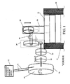
- FIG. 1 is shown in section the upper part of an eccentric-based forming press, as known from the prior art.
- the illustration thus essentially shows the head part of the press.
- the frame 10 of the press is shown only in sections. It can be a C-frame or a gate or any other frame.
- a classic AC or DC electric motor 12 drives via a belt drive 14 to a flywheel 16, which sits on a flywheel 18.
- a flywheel 16 On this shaft 18 is followed by a clutch 20, a brake 22, which - as known in the art - on demand and can be turned off.
- a gear 24 At the end of the flywheel mass shaft 18 sits a gear 24, which reduces the speed of the flywheel shaft 18 to a lower speed. The rotation is thus transmitted from the flywheel shaft 18 on the eccentric shaft 26 which is coupled to the large gear of the transmission.
- the eccentric shaft 26 opens into an eccentric bushing.
- the eccentric sleeve is enclosed by the head of a connecting rod 30, which converts the rotational movement of the eccentric shaft 26 together with the eccentric bushing 28 in an up and down movement.
- At the lower end of the connecting rod is attached to the connecting rod of the so-called plunger 32 with the coupling to any tool, which in turn is then adapted to act on a workpiece, which applies it to transform by a corresponding movement downward.
- a flywheel By means of an electric motor, a flywheel is driven via a belt drive, from which the movement is transmitted to the clutch bell via a small gear and a large gear (mounted on the eccentric shaft).
- the inner clutch bell presses against the clutch plate fitted with friction pads (wedged on the eccentric shaft), which then frictionally receives the movement of the gear wheel.
- the mechanically closed brake is pressed by means of a piston ring against the springs, and thus opened.
- the function of the clutch-brake combination is realized in that both are controlled with separate press safety valves, which are characterized by undercut or overlap against each other.
- the change from a driven with an electric motor eccentric press for forming sheet metal parts for the production of car hoods the energy for the forming-pressing operations in each case comes from the movement of a flywheel, wherein the movement of the flywheel is then switched on and off specifically for each pressing process. If the operator of this press wants to use the more modern and universally applicable technology of servo presses, he has no choice but to invest in a complete new system.
- the servo-forming presses have improved functionality and flexibility for the respective forming applications and in particular are more versatile that the movement of the plunger is arbitrarily programmable, thereby arbitrary path-time curves (also interposed with backward motion) perform leave, whereby a very flexible and if necessary very gentle workpiece machining can be done.
- this increased flexibility allows one and the same forming press can be used without major conversion today for forming sheet metal parts for steel hoods for trucks and tomorrow for aluminum hoods for small cars. The conversion
- a different type of press can be very much desired in order to be able to reshape a component according to the material requirements for different component sizes and materials.
- the old press which is not to be used, actually represents a very large operational value and therefore represents a waste of proven technology and resources in the scrapping of the old press. Since you can not easily dismantle a larger press machine and elsewhere, for example, after exporting to another country can build elsewhere, large losses in business terms in the transition from an old press to a new press to disadvantageously accept.
- It is therefore an object of the present invention is to remedy this situation and to show how you can continue to use cost-saving existing forming machines without having to do without the simultaneous use of modern drive technologies in the form of programmable servo drives.
- An essential idea of the present invention is to convert an existing forming machine, for example a forming press, whose forming force is generated in a mechanical way such that the existing drive motor, for example a DC or AC motor and the drive train from the electric motor to the flywheel, including clutch between the two elements and - if present - the flywheel is disassembled and a new drive, namely an electric servo drive is connected to the undeveloped shaft of the flywheel via a power transmission mechanism and all aggregates "downstream" seen in the power flow towards the workpiece remain and can be used further. From a technical point of view, the forces from the servo drive can also be transmitted directly to the eccentric shaft.
- the servo drive is an electrically functioning, freely programmable controllable servo motor.
- the eccentric with its socket, possibly the flywheel shaft, the connecting rod, the plunger, and of course the entire press frame available.
- the servo motor can transmit its power from the motor shaft to the former flywheel mass shaft via one or more V-belts, planetary gears or the like.
- V-belt pulleys and suitable tensioning devices for this V-belt transmission or another type of power transmission (transmission) are installed according to the prior art.
- the former flywheel shaft can be selectively rotated, whereby the thus realized rotation of the former flywheel shaft together with the existing eccentric mechanism causes the desired, realizable movement of the plunger.
- forming machines can be retrofitted by connecting a servo motor instead of an existing drive to a location in the drive train for the ram where there is room for, preferably at a drive shaft already existing on the machine prior to the start of the method, such as for example a flywheel or eccentric shaft.
- the other mechanical periphery such as frame, press table, workpiece feed, tool holder, brakes, or the transmission in the head of the machine.
- Particularly suitable are forming machines, which currently have a particularly massive, valuable and functional periphery, which thus represent a high operational value. If there is not enough room on an existing shaft, a new shaft can be installed, which provides enough space for the new coupling point.
- the scope of application of the invention includes not only press machines, but also rolling machines and bending machines, as well as cutting and punching machines.
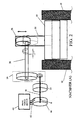
- FIG. 2 shows a schematic sketch of the forming press FIG. 1 After the inventive method has been applied to this device according to an embodiment thereof.
- the previously existing engine 12 together with the belt drive 14 is reduced to the flywheel 16, see FIG. 1 .
- the flywheel 16 is degraded.
- the clutch 20 is dismantled.
- an electric servo motor 40 is fixedly mounted in the vicinity of the pulleys 44, for example on the frame of the press head part, and a belt drive is mounted between the servo motor 40 and the pulleys 44.
- the belts are held tensioned by a tensioning device, as known in the art, so that any rotational movement of the axis of the servomotor 40 can be transmitted as free of play as possible via the mentioned plurality of belts.
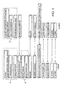
- FIG. 3 illustrates once again clearly which components can be retained on the forming device and which components are dismantled or which new components are added.
- the components indicated in box 50 are dismantled in this embodiment, the components from box 52 are newly added and all other components are retained.
- a modified transmission 24 is installed with a different gear ratio to allow for optimal matching between the kinematics of the servomotor and the kinematics of the eccentric movement.
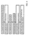
- FIG. 4 shows a schematic representation of the sequence of steps according to the invention in the inventive method according to the above embodiment.
- a first step 410 the flywheel 16 is removed from the flywheel shaft 18.
- step 420 the existing drive motor 12 including the belt 14 between flywheel and engine is dismantled.
- the clutch 20 is disassembled from the flywheel mass.
- the new servo drive is mounted, for example, at the same location of the pre-existing electric motor.
- a power transmission mechanism is mounted between the servo motor 40 and the flywheel shaft 18.
- this is a belt drive.
- any other power transmission mechanisms such as gears, gear connections, etc., may be used and correspondingly, other power transmission elements may be mounted to transmit the forces and movement of the motor axle to the flywheel shaft.
- the assembly takes place by means of fastening techniques known in the art.
- a control for the servo motor 40 is implemented which exactly meets the requirements required for any specific forming operation.
- the controller takes into account the possibly new kinematics of the new coupling point 8 for the introduction of force from the servomotor to the coupled drive shaft in the machine head part.
- a control of the brake 22 is implemented.
- FIG. 5 shows a schematic sketch of the forming press FIG. 1 after the method according to the invention has been applied to this device, with a coupling point 8 for a power transmission mechanism (42, 44 on the eccentric shaft 26 itself.
- the power transmission mechanism between servo motor 40 and the eccentric shaft 26 is made in this embodiment itself. That is, the flywheel mass shaft 18 and the brake 22 are degraded, and instead of the brake 22, another brake 46 is installed to brake the eccentric shaft itself. Thus, the new docking point 8 for the programmable Serrvoantrieb is made.
- This embodiment can now be changed in a meaningful way, for example, by the fact that the brake 22, the transmission gear 24 and the flywheel shaft 18 still remain in order to meet any existing safety requirements easier.
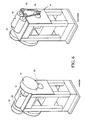
- FIG. 6 on the right shows the result of a further embodiment of the method according to the invention and on the right side according to the invention restructured forming in a further embodiment, in which a press frame in column construction is available and the existing press device (shown left) with a DC or AC motor 12, Clutch 20 and brake 22 in the drive train and a flywheel 16 as in the first-mentioned embodiment is present.
- the force is transmitted via an eccentric shaft 26 to the connecting rod and plunger.
- two synchronized servomotors 40 are mounted on the press frame, after the previously existing engine has been dismantled, including clutch and flywheel.
- the drive shafts of the newly installed servomotors are in this embodiment directly connected to the eccentric shaft 26 by installing a suitable power transmission system between these shafts. Shown here is a belt drive 42. However, any other suitable power transmission mechanism could be used.
- the subject matter of driving the servomotors of the present invention may be implemented in hardware, software, or a combination of both.
- This controller may also be embedded in a computer program product.
Landscapes
- Engineering & Computer Science (AREA)
- Mechanical Engineering (AREA)
- Press Drives And Press Lines (AREA)
Priority Applications (3)
| Application Number | Priority Date | Filing Date | Title |
|---|---|---|---|
| EP08019744A EP2186631A1 (fr) | 2008-11-12 | 2008-11-12 | Bancs de formage dotés d'un mode de fonctionnement efficace |
| PCT/DE2009/001562 WO2010054626A1 (fr) | 2008-11-12 | 2009-11-09 | Machines de formage à mode de fonctionnement efficace |
| DE112009003249T DE112009003249A5 (de) | 2008-11-12 | 2009-11-09 | Umformmaschinen mit effizienter betriebsweise |
Applications Claiming Priority (1)
| Application Number | Priority Date | Filing Date | Title |
|---|---|---|---|
| EP08019744A EP2186631A1 (fr) | 2008-11-12 | 2008-11-12 | Bancs de formage dotés d'un mode de fonctionnement efficace |
Publications (1)
| Publication Number | Publication Date |
|---|---|
| EP2186631A1 true EP2186631A1 (fr) | 2010-05-19 |
Family
ID=40494934
Family Applications (1)
| Application Number | Title | Priority Date | Filing Date |
|---|---|---|---|
| EP08019744A Withdrawn EP2186631A1 (fr) | 2008-11-12 | 2008-11-12 | Bancs de formage dotés d'un mode de fonctionnement efficace |
Country Status (3)
| Country | Link |
|---|---|
| EP (1) | EP2186631A1 (fr) |
| DE (1) | DE112009003249A5 (fr) |
| WO (1) | WO2010054626A1 (fr) |
Cited By (2)
| Publication number | Priority date | Publication date | Assignee | Title |
|---|---|---|---|---|
| DE102011104665A1 (de) * | 2011-06-06 | 2012-12-06 | Schuler Pressen Gmbh | Presse |
| WO2017089433A1 (fr) * | 2015-11-26 | 2017-06-01 | Schuler Pressen Gmbh | Procédé de fonctionnement d'une presse, en particulier d'une presse à vilebrequin d'estampage |
Citations (7)
| Publication number | Priority date | Publication date | Assignee | Title |
|---|---|---|---|---|
| US20040003729A1 (en) | 2002-07-04 | 2004-01-08 | Komatsu Artec Ltd. | Drive unit and drive method for press |
| DE102004009256A1 (de) | 2004-02-26 | 2005-09-15 | Schuler Pressen Gmbh & Co. Kg | Mechanische Mehrservopresse |
| EP1640145A1 (fr) | 2004-09-27 | 2006-03-29 | Burkhardt GmbH Maschinenfabrik | Entraînement direct et régulation pour presse à excentrique |
| WO2006136045A1 (fr) | 2005-06-22 | 2006-12-28 | Roland-Marcel Zumstein | Dispositif d'estampage et/ou de formage de toles, fils metalliques et similaires |
| DE102005040263A1 (de) | 2005-08-24 | 2007-03-01 | Müller Weingarten AG | Verfahren und Vorrichtung zur Steuerung und Regelung der Stößelbewegung an servo-elektrischen Pressen |
| EP1930149A1 (fr) | 2006-12-05 | 2008-06-11 | Burkhardt GmbH Maschinenfabrik | Entrainement pour presse à excentrique |
| WO2008149171A1 (fr) | 2007-06-06 | 2008-12-11 | Abb Research Ltd | Kit d'amélioration de moteur pour une presse mécanique |
-
2008
- 2008-11-12 EP EP08019744A patent/EP2186631A1/fr not_active Withdrawn
-
2009
- 2009-11-09 DE DE112009003249T patent/DE112009003249A5/de not_active Withdrawn
- 2009-11-09 WO PCT/DE2009/001562 patent/WO2010054626A1/fr not_active Ceased
Patent Citations (7)
| Publication number | Priority date | Publication date | Assignee | Title |
|---|---|---|---|---|
| US20040003729A1 (en) | 2002-07-04 | 2004-01-08 | Komatsu Artec Ltd. | Drive unit and drive method for press |
| DE102004009256A1 (de) | 2004-02-26 | 2005-09-15 | Schuler Pressen Gmbh & Co. Kg | Mechanische Mehrservopresse |
| EP1640145A1 (fr) | 2004-09-27 | 2006-03-29 | Burkhardt GmbH Maschinenfabrik | Entraînement direct et régulation pour presse à excentrique |
| WO2006136045A1 (fr) | 2005-06-22 | 2006-12-28 | Roland-Marcel Zumstein | Dispositif d'estampage et/ou de formage de toles, fils metalliques et similaires |
| DE102005040263A1 (de) | 2005-08-24 | 2007-03-01 | Müller Weingarten AG | Verfahren und Vorrichtung zur Steuerung und Regelung der Stößelbewegung an servo-elektrischen Pressen |
| EP1930149A1 (fr) | 2006-12-05 | 2008-06-11 | Burkhardt GmbH Maschinenfabrik | Entrainement pour presse à excentrique |
| WO2008149171A1 (fr) | 2007-06-06 | 2008-12-11 | Abb Research Ltd | Kit d'amélioration de moteur pour une presse mécanique |
Cited By (3)
| Publication number | Priority date | Publication date | Assignee | Title |
|---|---|---|---|---|
| DE102011104665A1 (de) * | 2011-06-06 | 2012-12-06 | Schuler Pressen Gmbh | Presse |
| WO2017089433A1 (fr) * | 2015-11-26 | 2017-06-01 | Schuler Pressen Gmbh | Procédé de fonctionnement d'une presse, en particulier d'une presse à vilebrequin d'estampage |
| CN108391425A (zh) * | 2015-11-26 | 2018-08-10 | 许勒压力机有限责任公司 | 用于运行压力机、尤其是锻造用曲柄压力机的方法 |
Also Published As
| Publication number | Publication date |
|---|---|
| DE112009003249A5 (de) | 2012-07-05 |
| WO2010054626A1 (fr) | 2010-05-20 |
| WO2010054626A4 (fr) | 2010-07-29 |
Similar Documents
| Publication | Publication Date | Title |
|---|---|---|
| EP0418779B1 (fr) | Méthode pour manufacture de pièces d'oeuvre par découpage, en particulier dans un outil à contre découpage à précision | |
| EP2895766B1 (fr) | Dispositif de rattrapage d'un frein à disque et frein à disque | |
| DE102009012111A1 (de) | Mechanische Umformpresse | |
| EP3096899B1 (fr) | Dispositif d'assemblage, de préférence de rivetage, clinchage ou poinçonnage | |
| EP2367676B1 (fr) | Procédé de régulation d'une presse à forger | |
| EP2512703A1 (fr) | Procédé et dispositif d'emboutissage de tôles | |
| DE102007022715A1 (de) | Presse | |
| DE102009055739A1 (de) | Umformmaschine, insbesondere Servopresse | |
| DE4335318A1 (de) | Werkzeugmaschine | |
| EP2186631A1 (fr) | Bancs de formage dotés d'un mode de fonctionnement efficace | |
| DE102015111227A1 (de) | Bearbeitungszange | |
| EP2319635A1 (fr) | Entraînement de presse et procédé de production d'un mouvement de levée d'une mise en place d'outils à l'aide d'un entraînement de presses | |
| CH695990A5 (de) | Pressmaschine, insbesondere Gelenkpresse. | |
| EP1930149A1 (fr) | Entrainement pour presse à excentrique | |
| EP3609648B1 (fr) | Procédé et dispositif d'ecrouissage par impact des rayons de transition d'un vilebrequin | |
| DE19925029A1 (de) | Verfahren zum Umformen und Vorrichtung zur Durchführung des Verfahrens | |
| DE102014112754A1 (de) | Stauchverfahren und Stauchvorrichtung | |
| DE102007044259B4 (de) | Ziehwerkzeug mit kurzem Kraftweg | |
| EP4414099A2 (fr) | Procédé de formage à chaud d'un bloc de forgeage coulé à l'aide d'un dispositif de forgeage | |
| DE3323428A1 (de) | Presse | |
| DE10230071C1 (de) | Zuhaltevorrichtung | |
| EP1523388A1 (fr) | Dispositif de maintien en position fermee | |
| DE4123495A1 (de) | Einrichtung zur nutzbremsung an exzenter- oder kurbelpressen | |
| DE102012102526A1 (de) | C-Gestell-Presse | |
| DE2918074A1 (de) | Mechanische presse |
Legal Events
| Date | Code | Title | Description |
|---|---|---|---|
| PUAI | Public reference made under article 153(3) epc to a published international application that has entered the european phase |
Free format text: ORIGINAL CODE: 0009012 |
|
| 17P | Request for examination filed |
Effective date: 20090129 |
|
| AK | Designated contracting states |
Kind code of ref document: A1 Designated state(s): AT BE BG CH CY CZ DE DK EE ES FI FR GB GR HR HU IE IS IT LI LT LU LV MC MT NL NO PL PT RO SE SI SK TR |
|
| AX | Request for extension of the european patent |
Extension state: AL BA MK RS |
|
| AKX | Designation fees paid |
Designated state(s): AT BE BG CH CY CZ DE DK EE ES FI FR GB GR HR HU IE IS IT LI LT LU LV MC MT NL NO PL PT RO SE SI SK TR |
|
| 17Q | First examination report despatched |
Effective date: 20111208 |
|
| STAA | Information on the status of an ep patent application or granted ep patent |
Free format text: STATUS: THE APPLICATION IS DEEMED TO BE WITHDRAWN |
|
| 18D | Application deemed to be withdrawn |
Effective date: 20120419 |