EP2367676B1 - Procédé de régulation d'une presse à forger - Google Patents
Procédé de régulation d'une presse à forger Download PDFInfo
- Publication number
- EP2367676B1 EP2367676B1 EP09806075.9A EP09806075A EP2367676B1 EP 2367676 B1 EP2367676 B1 EP 2367676B1 EP 09806075 A EP09806075 A EP 09806075A EP 2367676 B1 EP2367676 B1 EP 2367676B1
- Authority
- EP
- European Patent Office
- Prior art keywords
- ram
- plunger
- stroke range
- direct drive
- forming
- Prior art date
- Legal status (The legal status is an assumption and is not a legal conclusion. Google has not performed a legal analysis and makes no representation as to the accuracy of the status listed.)
- Active
Links
Images

Classifications
-
- B—PERFORMING OPERATIONS; TRANSPORTING
- B30—PRESSES
- B30B—PRESSES IN GENERAL
- B30B1/00—Presses, using a press ram, characterised by the features of the drive therefor, pressure being transmitted directly, or through simple thrust or tension members only, to the press ram or platen
- B30B1/26—Presses, using a press ram, characterised by the features of the drive therefor, pressure being transmitted directly, or through simple thrust or tension members only, to the press ram or platen by cams, eccentrics, or cranks
- B30B1/266—Drive systems for the cam, eccentric or crank axis
-
- B—PERFORMING OPERATIONS; TRANSPORTING
- B30—PRESSES
- B30B—PRESSES IN GENERAL
- B30B15/00—Details of, or accessories for, presses; Auxiliary measures in connection with pressing
- B30B15/14—Control arrangements for mechanically-driven presses
Definitions
- the invention relates to a method for operating a forming machine, in particular a forging press, or a forming system according to the preamble of claim 1.
- Mechanical forming machines or mechanical forming plants find in the industry a variety of applications.
- An essential category in this case are the forging-crank presses, in which, for the purpose of forming a workpiece, a ram acts on the workpiece via a drive with a defined deformation energy, thereby carrying out the desired forming.
- the Hubtaktiere and the residence time of the plunger in the individual Hubumblenabitesen essential parameters especially because of the residence time of the plunger in the upper stroke of the workpiece area for manipulation of the workpiece, for example, to replace the workpiece or for cooling the plunger is available.
- a pressing device in which the press ram is driven by a direct drive as the main drive, so that over any such trained press structure any curve of the ram stroke can be adjusted over time.
- the applicant also describes the configuration of the forge-type "Speed Forge” press, in which a rotary direct drive is used to manipulate the stroke time course, in which case the forming energy is provided shortly before the forming process energy-storing flywheel drive is engaged, which provides the plunger with the required forming energy available.
- a disadvantage of such methods is that extremely efficient direct drives are necessary for an almost freely configurable course of the plunger movement, so that the usually extremely heavy plunger can be driven with a conventionally required stroke rate of about 30 to 60 strokes per minute.
- an electric direct drive can take such a stroke-time curve, as for example in the DE 10 260 127 A1 are specified, extremely high power requirements are required, which in turn results in an extremely high power consumption and the resulting connection value, and in addition requires expensive and economically demanding direct drive motors.
- the document EP-A-947 259 discloses a method according to the preamble of claim 1.
- the object of the present invention is therefore to provide a method in which a stroke height-dependent modification of the plunger movement is provided, and the disadvantages of the prior art, in particular the need for powerful powerful and thus energy-consuming direct drive motors is reduced.
- this object is achieved by the characterizing part of claim 1.
- advantageous developments and expedient embodiments of the method according to the invention are given.
- the inventive method for operating a forming machine or a forming plant moves at least one arranged on a shaft via a hinge plunger, at least temporarily via a rotary drive, which provides the required deformation energy on the plunger and which is preferably designed as a flywheel drive , and which allows a defined plunger movement, ie a deviation from the classical sinus rhythm of an eccentric-driven crank press with concurrent eccentric speed.
- the method according to the invention is characterized in that the fall acceleration effectively acting on the plunger is adjusted via the direct drive, that the plunger experiences an acceleration force that reduces the fall acceleration in an upper stroke range by the direct drive and that the plunger at a predetermined fall speed, preferably in the lower stroke range, is engaged on the rotary drive.
- a force counteracting the weight force is necessary, which can be generated, for example, by a pneumatic ram weight compensation or the like.
- the movement of the plunger is controlled by the balance of power considerably flexible compared to the pure eccentric linkage.
- another direct drive acting on the ram, at least temporarily is provided, preferably a servomotor, which allows a defined periodic ram movement.
- a second direct drive preferably a servomotor
- the case of the ram is braked, so that the increase in movement speed per time is reduced compared to the free fall.
- the plunger is provided with the energy required for forming. The required deformation energy can thus be specified exactly by the flywheel.
- the direct drive carrying out the method is designed hydraulically.
- a hydraulic reaction force generation on the plunger for example, by a mounted in the ram guide hydraulic cylinder, the falling motion can be guided and adjusted.
- the direct drive is designed pneumatically.
- About a pneumatic design of the opposing force generating direct drive is achieved that learns about a pneumatic back pressure of the plunger a case acceleration reducing, preferably constant drag.
- By providing a sufficiently large pressure reservoir it is possible to keep the plunger with a constant counterforce quasi self-weight, and to modulate the acceleration of gravity to counteract this counterforce by the back pressure of the reservoir, for example by appropriate Dossel wornen.
- an accelerating force can in principle be exerted on the ram both by the hydraulic device, as well as by the pneumatic device.
- the plunger is decoupled from the rotary drive, in particular the flywheel drive at a predetermined speed, preferably in the lower stroke range.
- Such Abkupplungsvorgang usually takes place shortly after the conversion and releases the plunger back to the direct drive. In this way, the energy taken from the flywheel can be fed back to the flywheel by the flywheel drive independently of the plunger movement, and the plunger can be moved independently thereof.
- the ram weight compensation of the installation is used as the direct acceleration adapting the fall acceleration.
- a ram weight balance is often provided in such systems, in particular to compensate for the weight of the ram own weight, so that, for example, in the bearings of the joints on the eccentric shaft no complete displacement of the lubricant, and thereby damage the storage.
- Known ram weight compensations are usually designed such that via a pneumatic force acting on the plunger from below and from above is acted upon by a pressure, and the plunger itself thereby quasi free of weight on the eccentric shaft and the crank arranged thereon can be moved.
- Such a ram weight balance can now be used, for example, by reducing the plunger bottom pressure to put the plunger in a falling motion, wherein depending on the degree of pressure reduction, a corresponding counterforce due to the remaining residual pressure adjusts the fall acceleration.
- an accelerated drop movement is performed by the plunger in an upper stroke.
- the falling movement is caused by a force generated by the ram weight balance, namely an opposing force, influenced, wherein at the time of a defined, synchronized with the speed of the rotary drive falling speed of the rotary drive is coupled to the shaft, wherein the engagement process in the lower stroke, especially shortly before forming, and wherein shortly after the forming in the lower stroke the rotary drive at synchronized ram speed is disengaged again, and wherein the residence time of the plunger in the lower stroke range compared to the dwell time in the upper stroke range is shortened at least in the factor 1: 2.
- the method according to the invention can be used on the one hand in a single forming machine but on the other hand also in forming lines of a forming plant.
- Fig. 1 a forging crank press 1 with a movable plunger 2, which is articulated via cranks 3 to an eccentric shaft 4.
- a servomotor 5 and, on the other hand, a flywheel 7 are arranged via a coupling 6, wherein the flywheel 7 in turn can be driven by a flywheel drive 8.
- the in Fig. 1 plunger weight balance is preferably formed pneumatically and usually has a, the plunger upwardly driving lower pressure range (negative pressure) and the plunger down driving upper pressure range (top pressure).
- the ram weight balance can be formed in the ram guide or via a correspondingly attached to the ram piston in a pressure cylinder.
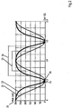
- Fig. 2 shows a stroke-time diagram 20, in which, by way of example, the ram stroke is plotted over time.
- the plunger at its upper reversal point at time 0 starts the movement, at time 0.5 and 1.5 seconds, a lower reversing position was reached and taken at time 1 and 2 seconds again the top dead center at maximum lift becomes.
- a conventional stroke course 21 which has the shape of a classic sinusoid, is shown, on the other hand an inventive stroke profile 22 of a drive system according to the invention, wherein the cycle times in the present case have been set to an equal number of strokes per minute.
- the conventional curve 21 is essentially described by a regular sinusoid, which is due to the direct articulation of the plunger on the eccentric shaft.
- a manipulation of the workpiece to be formed may take place in the lower region.
- manipulators can intervene in the forming machine, remove the workpiece and use a new workpiece.
- manipulators can remove or implement the workpiece, in which case an idle stroke can take place, during which, for example, a plunger cooling is performed.
- FIG Fig. 2 the region in which the tappet has pressure contact with the workpiece to be formed is shown in FIG Fig. 2 as an example, the pressure contact time 24 of the forming process indicated.
- this Druckberlickzeit ie during the deformation of the workpiece before retracting the plunger, thermal energy between the workpiece and the plunger can be replaced, whereby the plunger heats up.
- excessive ram heating involves disadvantages of reduced strength and thermal expansion, which in turn leads to increased tolerances.
- the Hubverlauf a ram 22 so is held by the reduced acceleration of gravity of the plunger over a longer period in the upper stroke range, ie above, for example, 150 mm stroke.
- the plunger can then be moved down by a corresponding influence on the acceleration on a steeper curve, wherein upon reaching a predetermined defined speed, for example at a lifting height of 50 mm, wherein always the speed sets the essential parameters, the flywheel 7 via the clutch 6 are engaged. If the ram speed present at the time of engagement corresponds exactly to the speed which is taken from a movement which is permanently synchronized with the flywheel, the coupling process takes place without wear or losses since no acceleration work has to be applied to the ram.
- the plunger is then in the lower deformation of the flywheel from the flywheel necessary for the transformation of energy, the movement during turn coupled to the flywheel state again corresponds to a sinusoidal shape.
- the area of the deformation 25, ie the duration of the forming contact with the workpiece is substantially reduced compared to the conventional course of the movement, whereby a less heat transfer of the workpiece takes place on the plunger.
- the time available for workpiece manipulation and tool cooling and tool lubrication is considerably extended by the extended residence time of the plunger in the upper stroke range.
- the plunger can remain in the upper stroke range for a period of time 26 when using a method according to the invention, as a result of which an improved number of cycles and improved tact quality can be achieved effectively.
- the ram speeds can thus be varied between 6 and 12 strokes per minute at the upper reversal point and between 30 and 60 and even 120 strokes per minute at the lower reversal point.
- the resulting average number of strokes of the machine is between 30 and 50 strokes / min.
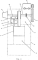
- FIG. 3 shows a schematic representation of a plant according to the invention with ram weight balance.
- the system is constructed in a conventional frame 30 not described in detail, which contains the necessary components, such as guides, leads, bearings, etc.
- the plunger 31 is guided in this context in a work area 32, wherein the representation of tools, etc. has been dispensed with.
- the plunger 31 is connected via a plunger linkage 33 with a shaft 34.
- the plunger linkage 33 transmits the rotary shaft movement of the shaft 34 into a required stroke movement of the plunger 31.
- a direct drive 35 such as a servo motor, arranged, which can take on the movement of the plunger influence.
- a coupling device 36 is further provided, which connects the shaft 34 in the engaged state with a flywheel 37. Via the flywheel 37, the plunger 31 is provided with the energy required for the forming process in the working area 32. Energy taken from the flywheel 37 for forming is fed back to the flywheel 37 through a flywheel drive 38 so that it is ready for the next forming cycle. Between the forming processes, the clutch 36 is opened, so that the plunger movement independent of the movement of the flywheel 37th can be done.
- a ram weight compensation 40 is provided on the plunger.
- the ram weight compensation 40 is shown here only very schematically and is intended to illustrate only the principle of its function.
- the overpressure P 1 can be easily reduced, so that the plunger 31 is pulled down by its weight. If necessary, such a movement can also be accelerated by an overpressure on the upper side 44, that is to say P 2 > P 1 .
- the ratios P 1 / P 2 are adjusted accordingly.
- the pressure ranges can be applied pneumatically, for example if a constant pressure is required over an enlarged pressure reservoir.
- the pneumatic control of the pressure ranges 43 and 44 can be carried out very easily and inexpensively via a pressure reservoir and simple drain or throttle valves. But it is also a hydraulic arrangement conceivable, for example, as undamped forces should be transmitted.
Landscapes
- Engineering & Computer Science (AREA)
- Mechanical Engineering (AREA)
- Press Drives And Press Lines (AREA)
- Forging (AREA)
- Control Of Presses (AREA)
Claims (7)
- Procédé de fonctionnement d'une machine de formage (1) ou d'une installation de formage avec au moins un poussoir (2, 31) disposé sur un arbre (4, 34) par le biais d'une articulation,- au moins un entraînement rotatif (7, 37) qui agit temporairement sur l'arbre (4, 34) fournissant une énergie de formage nécessaire sur le poussoir (2, 31), et- au moins un entraînement direct (5, 35, 40) qui agit temporairement sur le poussoir (2, 31) permettant un mouvement de poussoir défini,- l'accélération due à la pesanteur qui agit effectivement sur le poussoir (2, 31) étant adaptée par le biais de l'entraînement direct (5, 35, 40),caractérisé en ce que- dans une zone de levage supérieure, le poussoir (2, 31) subit du fait de l'entraînement direct (40) une force antagoniste réduisant l'accélération due à la pesanteur- en ce que, dans la zone de levage inférieure, pour une vitesse de chute prédéfinie, le poussoir (2, 31) est embrayé sur l'entraînement rotatif (7, 37).
- Procédé selon la revendication 1,
caractérisé en ce
qu'un autre entraînement direct agissant au moins temporairement sur le poussoir (2, 31), de préférence un servomoteur (5, 35), permet un mouvement de poussoir périodique défini. - Procédé selon l'une des revendications précédentes, caractérisé en ce que
l'entraînement direct (40) est constitué de façon hydraulique. - Procédé selon l'une des revendications précédentes, caractérisé en ce que
l'entraînement direct (40) est constitué de façon pneumatique. - Procédé selon l'une des revendications précédentes, caractérisé en ce que
le poussoir (2, 31), pour une vitesse prédéfinie, de préférence dans la zone de levage inférieure, est débrayé de l'entraînement rotatif (7, 37). - Procédé selon l'une des revendications précédentes, caractérisé en ce que
l'équilibrage du poids de poussoir (40) est mis en oeuvre en tant qu'entraînement direct adaptant l'accélération due à la pesanteur. - Procédé selon l'une des revendications précédentes, caractérisé en ce que- dans une zone de levage supérieure, le poussoir (2, 31) exécute un mouvement de chute accéléré,- le mouvement de chute est influencé, de préférence freiné, par une force produite par l'équilibrage du poids de poussoir (40),- au moment d'une vitesse de chute définie synchronisée avec la vitesse de l'entraînement rotatif (7, 37), l'entraînement rotatif (7, 37) est embrayé sur l'arbre (4, 34),- le processus d'embrayage survenant de préférence dans la zone de levage inférieure, en particulier peu avant le formage, et- peu après le formage, dans la zone de levage inférieure, l'entraînement rotatif (7, 37) est de nouveau débrayé pour une vitesse de poussoir synchronisée, et- la durée de séjour du poussoir dans la zone de levage inférieure est raccourcie d'au moins un facteur 1:2 par rapport à la durée de séjour dans la zone de levage supérieure.
Applications Claiming Priority (2)
| Application Number | Priority Date | Filing Date | Title |
|---|---|---|---|
| DE200810064229 DE102008064229A1 (de) | 2008-12-22 | 2008-12-22 | Verfahren zur Regelung einer Schmiedepresse |
| PCT/DE2009/001792 WO2010072208A2 (fr) | 2008-12-22 | 2009-12-21 | Procédé de régulation d'une presse à forger |
Publications (2)
| Publication Number | Publication Date |
|---|---|
| EP2367676A2 EP2367676A2 (fr) | 2011-09-28 |
| EP2367676B1 true EP2367676B1 (fr) | 2016-06-01 |
Family
ID=42201011
Family Applications (1)
| Application Number | Title | Priority Date | Filing Date |
|---|---|---|---|
| EP09806075.9A Active EP2367676B1 (fr) | 2008-12-22 | 2009-12-21 | Procédé de régulation d'une presse à forger |
Country Status (4)
| Country | Link |
|---|---|
| EP (1) | EP2367676B1 (fr) |
| DE (1) | DE102008064229A1 (fr) |
| ES (1) | ES2588992T3 (fr) |
| WO (1) | WO2010072208A2 (fr) |
Families Citing this family (6)
| Publication number | Priority date | Publication date | Assignee | Title |
|---|---|---|---|---|
| DE102009050390A1 (de) * | 2009-10-22 | 2011-04-28 | Müller Weingarten AG | Arbeitsverfahren und Einrichtung zum Betreiben von Pressen |
| DE102010049492B4 (de) | 2010-10-27 | 2013-04-18 | Schuler Pressen Gmbh | Mechanische Umformmaschine, insbesondere Kurbelpresse sowie Verfahren zur Bereitstellung einer mechanischen Umformmaschine |
| JP5770584B2 (ja) | 2011-09-27 | 2015-08-26 | 住友重機械工業株式会社 | 鍛造プレス装置およびその制御方法 |
| DE102012108933B4 (de) * | 2012-09-21 | 2019-08-08 | Schuler Pressen Gmbh | Verfahren zum Betreiben einer Werkzeugmaschine oder Arbeitsmaschine und danach ausgeführte Werkzeugmaschine oder Arbeitsmaschine mit einer Verbindungsanordnung für ein Hubelement |
| DE102015222995A1 (de) * | 2015-11-20 | 2017-05-24 | Sms Group Gmbh | Weggebundene Presse mit Kulissenstein |
| EP4003677B1 (fr) * | 2019-07-30 | 2026-04-08 | Kama GmbH | Entraînement oscillant de machine |
Citations (1)
| Publication number | Priority date | Publication date | Assignee | Title |
|---|---|---|---|---|
| US20070062247A1 (en) * | 2005-08-16 | 2007-03-22 | Schuler Pressen Gmnh & Co. Kg | Press driving module and method of providing a press line |
Family Cites Families (10)
| Publication number | Priority date | Publication date | Assignee | Title |
|---|---|---|---|---|
| US3869927A (en) * | 1973-09-06 | 1975-03-11 | Gulf & Western Ind Prod Co | Geared drag link-slider-crank press |
| FR2296518A1 (fr) * | 1975-01-06 | 1976-07-30 | Gulf & Western Mfg Co | Presse mecanique de travail du metal |
| JP2570812B2 (ja) * | 1988-05-31 | 1997-01-16 | 石川島播磨重工業株式会社 | 鍛造プレス装置 |
| DD291294A5 (de) * | 1989-12-29 | 1991-06-27 | Komb. Umformtechnik "Herbert Warnke",De | Einrichtung zur steuerung des energetischen und dynamischen verhaltens von antrieben in umformmaschinen |
| JPH0751900A (ja) * | 1993-08-21 | 1995-02-28 | Sumitomo Heavy Ind Ltd | クランクプレスのバランサ吊上げ力制御方法及びそのための装置 |
| JPH08197298A (ja) * | 1995-01-26 | 1996-08-06 | Amada Co Ltd | スライドモーション可変プレス |
| US6453806B1 (en) * | 1998-03-26 | 2002-09-24 | The Minster Machine Company | Infinite variable slide motion for a mechanical power press |
| JP3437758B2 (ja) * | 1998-03-31 | 2003-08-18 | 住友重機械工業株式会社 | クランクプレス |
| EP2261018B1 (fr) * | 2002-06-18 | 2018-10-17 | AMADA Company, Ltd. | Procédé de régulation d'un système de commande asservie et système de commande asservie de presse |
| DE10260127A1 (de) | 2002-12-19 | 2004-07-15 | Siemens Ag | Pressvorrichtung |
-
2008
- 2008-12-22 DE DE200810064229 patent/DE102008064229A1/de not_active Ceased
-
2009
- 2009-12-21 WO PCT/DE2009/001792 patent/WO2010072208A2/fr not_active Ceased
- 2009-12-21 EP EP09806075.9A patent/EP2367676B1/fr active Active
- 2009-12-21 ES ES09806075.9T patent/ES2588992T3/es active Active
Patent Citations (1)
| Publication number | Priority date | Publication date | Assignee | Title |
|---|---|---|---|---|
| US20070062247A1 (en) * | 2005-08-16 | 2007-03-22 | Schuler Pressen Gmnh & Co. Kg | Press driving module and method of providing a press line |
Also Published As
| Publication number | Publication date |
|---|---|
| WO2010072208A2 (fr) | 2010-07-01 |
| ES2588992T3 (es) | 2016-11-08 |
| WO2010072208A3 (fr) | 2010-12-29 |
| DE102008064229A1 (de) | 2010-07-01 |
| EP2367676A2 (fr) | 2011-09-28 |
Similar Documents
| Publication | Publication Date | Title |
|---|---|---|
| EP2697005B1 (fr) | Procédé permettant de faire fonctionner une presse équipée d'un entraînement inférieur et presse fonctionnant selon ledit procédé | |
| EP2608952B1 (fr) | Procédé pour faire fonctionner une presse équipée d'un sous-entraînement et presse utilisée selon le procédé | |
| DE102004009256B4 (de) | Mechanische Mehrservopresse | |
| EP2367676B1 (fr) | Procédé de régulation d'une presse à forger | |
| DE102010060103B4 (de) | Ziehpresse mit dynamisch optimierter Blechhaltung | |
| DE102014201470A1 (de) | Presse und Verfahren zur Steuerung des Pressenstößels | |
| EP3377311B1 (fr) | Presse à course imposée dotée d'un coulisseau | |
| EP2077167A2 (fr) | Procédé pour l'entraînement économe en énergie d'une presse hydraulique et presse économe en énergie et à faible entretien | |
| EP2686161B1 (fr) | Presse d'emboutissage dotée de deux coulisseaux accouplables | |
| EP0929396B1 (fr) | Procede de controle de la vitesse d'un coulisseau de presse dans une presse de formage, et dispositif de commande de ce coulisseau | |
| DE102012217276B4 (de) | Schmiedepresse und Verfahren zum Steuern dieser | |
| DE2319032A1 (de) | Schnellhubschmiedepresse | |
| AT507110A1 (de) | Presse zum umformen von material | |
| DE2132377C3 (de) | Umformmaschine zum wahlweisen Pressen oder Schlagen | |
| DE3323428C2 (fr) | ||
| DE2625881A1 (de) | Stufenpresse | |
| EP2490886B1 (fr) | Procédé de fonctionnement et dispositif destiné à faire fonctionner des presses | |
| WO2017186234A1 (fr) | Presse-transfert pourvue d'un serre-flan en c | |
| DD295589A5 (de) | Einrichtung zur Nutzbremsung an Exzenter- oder Kurbelpressen | |
| WO2008141607A1 (fr) | Entrainement hybride pour une presse de transfert à plusieurs coulisseaux ou un train de presse | |
| DE10215003A1 (de) | Hydraulische Presse | |
| DE102023113473B4 (de) | Hydraulische Umformmaschine zur Werkstückumformung, Hydrauliksteuereinheit und Verfahren zur Steuerung eines Hydraulikzylinders einer hydraulischen Umformmaschine | |
| DD204384A5 (de) | Verfahren und einrichtung zum pressformen von gegenstaenden | |
| DE892847C (de) | Waagerechtschmiede- und Stauchmaschine mit waagerecht geteilten Klemmbacken | |
| WO2010054626A1 (fr) | Machines de formage à mode de fonctionnement efficace |
Legal Events
| Date | Code | Title | Description |
|---|---|---|---|
| PUAI | Public reference made under article 153(3) epc to a published international application that has entered the european phase |
Free format text: ORIGINAL CODE: 0009012 |
|
| 17P | Request for examination filed |
Effective date: 20110506 |
|
| AK | Designated contracting states |
Kind code of ref document: A2 Designated state(s): AT BE BG CH CY CZ DE DK EE ES FI FR GB GR HR HU IE IS IT LI LT LU LV MC MK MT NL NO PL PT RO SE SI SK SM TR |
|
| RIN1 | Information on inventor provided before grant (corrected) |
Inventor name: REUTER, HELMUT Inventor name: BIEG, MARKUS Inventor name: SCHNEIDER, ALEXANDER |
|
| DAX | Request for extension of the european patent (deleted) | ||
| 17Q | First examination report despatched |
Effective date: 20131126 |
|
| GRAP | Despatch of communication of intention to grant a patent |
Free format text: ORIGINAL CODE: EPIDOSNIGR1 |
|
| INTG | Intention to grant announced |
Effective date: 20160202 |
|
| RAP1 | Party data changed (applicant data changed or rights of an application transferred) |
Owner name: SCHULER PRESSEN GMBH |
|
| GRAS | Grant fee paid |
Free format text: ORIGINAL CODE: EPIDOSNIGR3 |
|
| GRAA | (expected) grant |
Free format text: ORIGINAL CODE: 0009210 |
|
| AK | Designated contracting states |
Kind code of ref document: B1 Designated state(s): AT BE BG CH CY CZ DE DK EE ES FI FR GB GR HR HU IE IS IT LI LT LU LV MC MK MT NL NO PL PT RO SE SI SK SM TR |
|
| REG | Reference to a national code |
Ref country code: GB Ref legal event code: FG4D Free format text: NOT ENGLISH |
|
| REG | Reference to a national code |
Ref country code: CH Ref legal event code: EP Ref country code: AT Ref legal event code: REF Ref document number: 803616 Country of ref document: AT Kind code of ref document: T Effective date: 20160615 |
|
| REG | Reference to a national code |
Ref country code: IE Ref legal event code: FG4D Free format text: LANGUAGE OF EP DOCUMENT: GERMAN |
|
| REG | Reference to a national code |
Ref country code: DE Ref legal event code: R096 Ref document number: 502009012657 Country of ref document: DE |
|
| REG | Reference to a national code |
Ref country code: LT Ref legal event code: MG4D |
|
| REG | Reference to a national code |
Ref country code: NL Ref legal event code: MP Effective date: 20160601 |
|
| PG25 | Lapsed in a contracting state [announced via postgrant information from national office to epo] |
Ref country code: FI Free format text: LAPSE BECAUSE OF FAILURE TO SUBMIT A TRANSLATION OF THE DESCRIPTION OR TO PAY THE FEE WITHIN THE PRESCRIBED TIME-LIMIT Effective date: 20160601 Ref country code: LT Free format text: LAPSE BECAUSE OF FAILURE TO SUBMIT A TRANSLATION OF THE DESCRIPTION OR TO PAY THE FEE WITHIN THE PRESCRIBED TIME-LIMIT Effective date: 20160601 Ref country code: NO Free format text: LAPSE BECAUSE OF FAILURE TO SUBMIT A TRANSLATION OF THE DESCRIPTION OR TO PAY THE FEE WITHIN THE PRESCRIBED TIME-LIMIT Effective date: 20160901 |
|
| REG | Reference to a national code |
Ref country code: ES Ref legal event code: FG2A Ref document number: 2588992 Country of ref document: ES Kind code of ref document: T3 Effective date: 20161108 |
|
| PG25 | Lapsed in a contracting state [announced via postgrant information from national office to epo] |
Ref country code: LV Free format text: LAPSE BECAUSE OF FAILURE TO SUBMIT A TRANSLATION OF THE DESCRIPTION OR TO PAY THE FEE WITHIN THE PRESCRIBED TIME-LIMIT Effective date: 20160601 Ref country code: NL Free format text: LAPSE BECAUSE OF FAILURE TO SUBMIT A TRANSLATION OF THE DESCRIPTION OR TO PAY THE FEE WITHIN THE PRESCRIBED TIME-LIMIT Effective date: 20160601 Ref country code: GR Free format text: LAPSE BECAUSE OF FAILURE TO SUBMIT A TRANSLATION OF THE DESCRIPTION OR TO PAY THE FEE WITHIN THE PRESCRIBED TIME-LIMIT Effective date: 20160902 Ref country code: HR Free format text: LAPSE BECAUSE OF FAILURE TO SUBMIT A TRANSLATION OF THE DESCRIPTION OR TO PAY THE FEE WITHIN THE PRESCRIBED TIME-LIMIT Effective date: 20160601 Ref country code: SE Free format text: LAPSE BECAUSE OF FAILURE TO SUBMIT A TRANSLATION OF THE DESCRIPTION OR TO PAY THE FEE WITHIN THE PRESCRIBED TIME-LIMIT Effective date: 20160601 |
|
| PG25 | Lapsed in a contracting state [announced via postgrant information from national office to epo] |
Ref country code: CZ Free format text: LAPSE BECAUSE OF FAILURE TO SUBMIT A TRANSLATION OF THE DESCRIPTION OR TO PAY THE FEE WITHIN THE PRESCRIBED TIME-LIMIT Effective date: 20160601 Ref country code: SK Free format text: LAPSE BECAUSE OF FAILURE TO SUBMIT A TRANSLATION OF THE DESCRIPTION OR TO PAY THE FEE WITHIN THE PRESCRIBED TIME-LIMIT Effective date: 20160601 Ref country code: IS Free format text: LAPSE BECAUSE OF FAILURE TO SUBMIT A TRANSLATION OF THE DESCRIPTION OR TO PAY THE FEE WITHIN THE PRESCRIBED TIME-LIMIT Effective date: 20161001 Ref country code: RO Free format text: LAPSE BECAUSE OF FAILURE TO SUBMIT A TRANSLATION OF THE DESCRIPTION OR TO PAY THE FEE WITHIN THE PRESCRIBED TIME-LIMIT Effective date: 20160601 Ref country code: EE Free format text: LAPSE BECAUSE OF FAILURE TO SUBMIT A TRANSLATION OF THE DESCRIPTION OR TO PAY THE FEE WITHIN THE PRESCRIBED TIME-LIMIT Effective date: 20160601 |
|
| PG25 | Lapsed in a contracting state [announced via postgrant information from national office to epo] |
Ref country code: PT Free format text: LAPSE BECAUSE OF FAILURE TO SUBMIT A TRANSLATION OF THE DESCRIPTION OR TO PAY THE FEE WITHIN THE PRESCRIBED TIME-LIMIT Effective date: 20161003 Ref country code: SM Free format text: LAPSE BECAUSE OF FAILURE TO SUBMIT A TRANSLATION OF THE DESCRIPTION OR TO PAY THE FEE WITHIN THE PRESCRIBED TIME-LIMIT Effective date: 20160601 Ref country code: PL Free format text: LAPSE BECAUSE OF FAILURE TO SUBMIT A TRANSLATION OF THE DESCRIPTION OR TO PAY THE FEE WITHIN THE PRESCRIBED TIME-LIMIT Effective date: 20160601 |
|
| REG | Reference to a national code |
Ref country code: DE Ref legal event code: R097 Ref document number: 502009012657 Country of ref document: DE |
|
| PLBE | No opposition filed within time limit |
Free format text: ORIGINAL CODE: 0009261 |
|
| STAA | Information on the status of an ep patent application or granted ep patent |
Free format text: STATUS: NO OPPOSITION FILED WITHIN TIME LIMIT |
|
| 26N | No opposition filed |
Effective date: 20170302 |
|
| PG25 | Lapsed in a contracting state [announced via postgrant information from national office to epo] |
Ref country code: BE Free format text: LAPSE BECAUSE OF NON-PAYMENT OF DUE FEES Effective date: 20161231 Ref country code: DK Free format text: LAPSE BECAUSE OF FAILURE TO SUBMIT A TRANSLATION OF THE DESCRIPTION OR TO PAY THE FEE WITHIN THE PRESCRIBED TIME-LIMIT Effective date: 20160601 Ref country code: SI Free format text: LAPSE BECAUSE OF FAILURE TO SUBMIT A TRANSLATION OF THE DESCRIPTION OR TO PAY THE FEE WITHIN THE PRESCRIBED TIME-LIMIT Effective date: 20160601 |
|
| REG | Reference to a national code |
Ref country code: CH Ref legal event code: PL |
|
| GBPC | Gb: european patent ceased through non-payment of renewal fee |
Effective date: 20161221 |
|
| PG25 | Lapsed in a contracting state [announced via postgrant information from national office to epo] |
Ref country code: MC Free format text: LAPSE BECAUSE OF FAILURE TO SUBMIT A TRANSLATION OF THE DESCRIPTION OR TO PAY THE FEE WITHIN THE PRESCRIBED TIME-LIMIT Effective date: 20160601 |
|
| REG | Reference to a national code |
Ref country code: FR Ref legal event code: ST Effective date: 20170831 |
|
| REG | Reference to a national code |
Ref country code: IE Ref legal event code: MM4A |
|
| PG25 | Lapsed in a contracting state [announced via postgrant information from national office to epo] |
Ref country code: LI Free format text: LAPSE BECAUSE OF NON-PAYMENT OF DUE FEES Effective date: 20161231 Ref country code: FR Free format text: LAPSE BECAUSE OF NON-PAYMENT OF DUE FEES Effective date: 20170102 Ref country code: CH Free format text: LAPSE BECAUSE OF NON-PAYMENT OF DUE FEES Effective date: 20161231 Ref country code: LU Free format text: LAPSE BECAUSE OF NON-PAYMENT OF DUE FEES Effective date: 20161221 |
|
| PG25 | Lapsed in a contracting state [announced via postgrant information from national office to epo] |
Ref country code: GB Free format text: LAPSE BECAUSE OF NON-PAYMENT OF DUE FEES Effective date: 20161221 Ref country code: IE Free format text: LAPSE BECAUSE OF NON-PAYMENT OF DUE FEES Effective date: 20161221 |
|
| REG | Reference to a national code |
Ref country code: BE Ref legal event code: MM Effective date: 20161231 |
|
| REG | Reference to a national code |
Ref country code: AT Ref legal event code: MM01 Ref document number: 803616 Country of ref document: AT Kind code of ref document: T Effective date: 20161221 |
|
| PG25 | Lapsed in a contracting state [announced via postgrant information from national office to epo] |
Ref country code: CY Free format text: LAPSE BECAUSE OF FAILURE TO SUBMIT A TRANSLATION OF THE DESCRIPTION OR TO PAY THE FEE WITHIN THE PRESCRIBED TIME-LIMIT Effective date: 20160601 Ref country code: AT Free format text: LAPSE BECAUSE OF NON-PAYMENT OF DUE FEES Effective date: 20161221 Ref country code: HU Free format text: LAPSE BECAUSE OF FAILURE TO SUBMIT A TRANSLATION OF THE DESCRIPTION OR TO PAY THE FEE WITHIN THE PRESCRIBED TIME-LIMIT; INVALID AB INITIO Effective date: 20091221 |
|
| PG25 | Lapsed in a contracting state [announced via postgrant information from national office to epo] |
Ref country code: TR Free format text: LAPSE BECAUSE OF FAILURE TO SUBMIT A TRANSLATION OF THE DESCRIPTION OR TO PAY THE FEE WITHIN THE PRESCRIBED TIME-LIMIT Effective date: 20160601 Ref country code: MK Free format text: LAPSE BECAUSE OF FAILURE TO SUBMIT A TRANSLATION OF THE DESCRIPTION OR TO PAY THE FEE WITHIN THE PRESCRIBED TIME-LIMIT Effective date: 20160601 |
|
| PG25 | Lapsed in a contracting state [announced via postgrant information from national office to epo] |
Ref country code: BG Free format text: LAPSE BECAUSE OF FAILURE TO SUBMIT A TRANSLATION OF THE DESCRIPTION OR TO PAY THE FEE WITHIN THE PRESCRIBED TIME-LIMIT Effective date: 20160601 |
|
| PG25 | Lapsed in a contracting state [announced via postgrant information from national office to epo] |
Ref country code: MT Free format text: LAPSE BECAUSE OF FAILURE TO SUBMIT A TRANSLATION OF THE DESCRIPTION OR TO PAY THE FEE WITHIN THE PRESCRIBED TIME-LIMIT Effective date: 20160601 |
|
| PGFP | Annual fee paid to national office [announced via postgrant information from national office to epo] |
Ref country code: IT Payment date: 20181218 Year of fee payment: 10 |
|
| PGFP | Annual fee paid to national office [announced via postgrant information from national office to epo] |
Ref country code: ES Payment date: 20190121 Year of fee payment: 10 |
|
| PG25 | Lapsed in a contracting state [announced via postgrant information from national office to epo] |
Ref country code: IT Free format text: LAPSE BECAUSE OF NON-PAYMENT OF DUE FEES Effective date: 20191221 |
|
| REG | Reference to a national code |
Ref country code: ES Ref legal event code: FD2A Effective date: 20210525 |
|
| PG25 | Lapsed in a contracting state [announced via postgrant information from national office to epo] |
Ref country code: ES Free format text: LAPSE BECAUSE OF NON-PAYMENT OF DUE FEES Effective date: 20191222 |
|
| P01 | Opt-out of the competence of the unified patent court (upc) registered |
Effective date: 20230526 |
|
| REG | Reference to a national code |
Ref country code: DE Ref legal event code: R082 Ref document number: 502009012657 Country of ref document: DE Representative=s name: RAVENSPAT PATENTANWAELTE PARTNERSCHAFT MBB, DE |
|
| PGFP | Annual fee paid to national office [announced via postgrant information from national office to epo] |
Ref country code: DE Payment date: 20250826 Year of fee payment: 17 |