EP3096899B1 - Dispositif d'assemblage, de préférence de rivetage, clinchage ou poinçonnage - Google Patents
Dispositif d'assemblage, de préférence de rivetage, clinchage ou poinçonnage Download PDFInfo
- Publication number
- EP3096899B1 EP3096899B1 EP15700366.6A EP15700366A EP3096899B1 EP 3096899 B1 EP3096899 B1 EP 3096899B1 EP 15700366 A EP15700366 A EP 15700366A EP 3096899 B1 EP3096899 B1 EP 3096899B1
- Authority
- EP
- European Patent Office
- Prior art keywords
- punch
- spindle
- sleeve
- joining device
- movement
- Prior art date
- Legal status (The legal status is an assumption and is not a legal conclusion. Google has not performed a legal analysis and makes no representation as to the accuracy of the status listed.)
- Active
Links
Images



Classifications
-
- B—PERFORMING OPERATIONS; TRANSPORTING
- B21—MECHANICAL METAL-WORKING WITHOUT ESSENTIALLY REMOVING MATERIAL; PUNCHING METAL
- B21J—FORGING; HAMMERING; PRESSING METAL; RIVETING; FORGE FURNACES
- B21J15/00—Riveting
- B21J15/02—Riveting procedures
- B21J15/025—Setting self-piercing rivets
-
- B—PERFORMING OPERATIONS; TRANSPORTING
- B21—MECHANICAL METAL-WORKING WITHOUT ESSENTIALLY REMOVING MATERIAL; PUNCHING METAL
- B21D—WORKING OR PROCESSING OF SHEET METAL OR METAL TUBES, RODS OR PROFILES WITHOUT ESSENTIALLY REMOVING MATERIAL; PUNCHING METAL
- B21D39/00—Application of procedures in order to connect objects or parts, e.g. coating with sheet metal otherwise than by plating; Tube expanders
- B21D39/03—Application of procedures in order to connect objects or parts, e.g. coating with sheet metal otherwise than by plating; Tube expanders of sheet metal otherwise than by folding
-
- B—PERFORMING OPERATIONS; TRANSPORTING
- B21—MECHANICAL METAL-WORKING WITHOUT ESSENTIALLY REMOVING MATERIAL; PUNCHING METAL
- B21J—FORGING; HAMMERING; PRESSING METAL; RIVETING; FORGE FURNACES
- B21J15/00—Riveting
- B21J15/10—Riveting machines
-
- B—PERFORMING OPERATIONS; TRANSPORTING
- B21—MECHANICAL METAL-WORKING WITHOUT ESSENTIALLY REMOVING MATERIAL; PUNCHING METAL
- B21J—FORGING; HAMMERING; PRESSING METAL; RIVETING; FORGE FURNACES
- B21J15/00—Riveting
- B21J15/10—Riveting machines
- B21J15/16—Drives for riveting machines; Transmission means therefor
- B21J15/20—Drives for riveting machines; Transmission means therefor operated by hydraulic or liquid pressure
-
- B—PERFORMING OPERATIONS; TRANSPORTING
- B21—MECHANICAL METAL-WORKING WITHOUT ESSENTIALLY REMOVING MATERIAL; PUNCHING METAL
- B21J—FORGING; HAMMERING; PRESSING METAL; RIVETING; FORGE FURNACES
- B21J15/00—Riveting
- B21J15/10—Riveting machines
- B21J15/16—Drives for riveting machines; Transmission means therefor
- B21J15/22—Drives for riveting machines; Transmission means therefor operated by both hydraulic or liquid pressure and gas pressure
-
- B—PERFORMING OPERATIONS; TRANSPORTING
- B21—MECHANICAL METAL-WORKING WITHOUT ESSENTIALLY REMOVING MATERIAL; PUNCHING METAL
- B21J—FORGING; HAMMERING; PRESSING METAL; RIVETING; FORGE FURNACES
- B21J15/00—Riveting
- B21J15/10—Riveting machines
- B21J15/16—Drives for riveting machines; Transmission means therefor
- B21J15/26—Drives for riveting machines; Transmission means therefor operated by rotary drive, e.g. by electric motor
-
- B—PERFORMING OPERATIONS; TRANSPORTING
- B21—MECHANICAL METAL-WORKING WITHOUT ESSENTIALLY REMOVING MATERIAL; PUNCHING METAL
- B21D—WORKING OR PROCESSING OF SHEET METAL OR METAL TUBES, RODS OR PROFILES WITHOUT ESSENTIALLY REMOVING MATERIAL; PUNCHING METAL
- B21D28/00—Shaping by press-cutting; Perforating
- B21D28/24—Perforating, i.e. punching holes
- B21D28/26—Perforating, i.e. punching holes in sheets or flat parts
Definitions
- the present invention relates to a joining device, preferably for setting rivets, for clinching or for punching.
- the DE 103 59 879 A1 describes a joining device and forms the basis for the preamble of claims 1 and 3.
- Previously known joining devices for example for semi-hollow punching riveting, solid punching riveting or clinching, have a C-shaped carrier. At one end of the C-shaped support is a solid die. At the other end of the C-shaped support a movable punch is arranged. The objects to be joined are arranged between the die and the stamp.
- the drive is carried out hydraulically, pneumatically or servo-electric. Typical drive lengths over which the punch must be movable are greater than 350 mm. This long interference geometry leads to accessibility problems at the joint. Flanges must be hired, joining facilities turned, vehicle concepts changed to ensure accessibility with existing plant technology. At some joints, these above-mentioned cheap joining options must be replaced by costly methods, such as blind rivets.
- the linear movement of the punch carried out by the pre-stroke unit can also be referred to as rapid lift or feed stroke. It is crucial that the punch is moved very quickly and over a long distance to the joint by means of the Vorhubech. During the pre-stroke no or only a very small force acts on the punch. The mechanism for carrying out the preliminary stroke can thus act very quickly and does not have to apply any joining force. As soon as the punch or downholder reaches the joint, the working stroke unit acts. This then only has to move the stamp over a very short distance, but with a great force. During the working stroke, for example, the punch only has to be moved over a distance of less than approximately 20 mm, but with a force of 5 to 100 kN.
- the stamp can be closed very quickly and reopened. This results in improved accessibility to joints and it can be used simple joining methods, such as semi-punched or rivet riveting or clinching.
- the joining device according to the invention is relatively lightweight and can be moved for example by robots and thus used for the assembly of vehicle bodies. This results in a cost and space savings.
- Pre-lift unit is a quick opening and closing of the punch possible, which reduces the assembly times and thus the costs.
- the Vorhubech comprises a first spindle for moving the punch
- the power stroke unit comprises a second spindle for moving the punch.
- the spindles have in particular different pitches, so that different speeds and forces can be generated by means of different spindles.
- the two spindles are arranged one inside the other. As a result, a compact construction of the joining device is possible.
- the two spindles are drive-connected via a differential gear with a common drive.
- the differential gear By means of the differential gear, the first spindle of the Vorhubü is first actuated when closing the punch and then the second spindle of the working stroke unit is actuated.
- the drive is preferably designed as an electric motor or hydraulic motor.
- the Vorhubaji comprises a first spindle.
- This first spindle is connected to the stamp.
- the working stroke unit comprises a sleeve guided linearly movably on the support and a movement device.
- the movement device is designed for linear movement of this sleeve.
- the first spindle of the Vorhubech is guided in this sleeve.
- There is a driver between the first spindle and the sleeve so that the first spindle together with the punch is moved by linear movement of the sleeve.
- the stamp can be brought very quickly and with little force to the joint.
- the sleeve is moved linearly by means of the movement device. With the sleeve, the first spindle and thus the punch moves.
- a backdrop is preferably provided.
- This backdrop includes an oblique groove.
- a pin is guided.
- a corresponding force acts on the pin.
- Either the scenery or the pin is connected to the linearly movable guided sleeve so that a force can be transmitted to the linear guided sleeve on the movement device.
- the term "pen” is broad and includes, for example, a sliding block.
- the gate is preferably provided to connect a hinge lever with the linear guided sleeve. Also on this articulated lever can act a linear force. This is transmitted via the toggle lever on the sleeve.
- the first spindle is drive-connected to a drive and that the movement device is drive-connected to a further drive.
- the drive of the spindle is preferably designed as an electric motor or hydraulic motor.
- the further drive of the moving device is preferably designed as a hydraulic cylinder or pneumatic cylinder.
- the first spindle and the movement device are drive-connected via a transmission with a common drive. This gear is designed so that when closing the punch, first the force acts on the first spindle and subsequently the linearly movable sleeve is displaced via the movement device.
- the Vorhubaji has a hydraulically or pneumatically driven cylinder.
- This cylinder is connected to the plunger and comprises a piston and a piston rod.
- the power stroke unit has an engagement element. This engagement element is used for direct power transmission to the piston rod or the piston.
- a thread is formed between the engagement element and the piston or the piston rod.
- This thread is in particular a fine thread. This thread can be moved over a short distance but with high force of the piston.
- the engagement element of the power stroke unit is preferably moved via an electric motor or hydraulic motor.
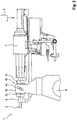
- the joining device 1 has a C-shaped carrier 4. At one end of the C-shaped support 4 is a stationary die 2. At the other end of the C-shaped support 4, a punch 3 is movably received. Between the punch 3 and the die 2, the objects to be joined are positioned.
- the joining device 1 is used for example for clinching, punching or for setting rivets.
- the Vorhubech 5 comprises a first spindle 8 and the working stroke unit 6 a second Spindle 9.
- the two spindles 8, 9 are arranged one inside the other and one of the two spindles 8, 9 is connected directly to the punch 3.
- a differential gear is provided between the two spindles 8, 9 and a drive 7, a differential gear is provided. This differential gear initially distributes the power of the drive 7 to the first spindle 8 to deliver the punch 3 quickly. Then the force of the drive 7 is transmitted to the second spindle 9.
- FIG. 1 an X and Y direction.
- the delivery of the punch 3 takes place against the die 2.
- the Y direction is perpendicular to the X direction.
- the drive 7 is designed as an electric motor or hydraulic motor.
- FIG. 2 shows the joining device 1 according to the second embodiment. For the sake of clarity are in the Figures 2 and 3 only sections of the joining device 1 shown.
- the advance unit 5 has the first spindle 8. This first spindle 8 is connected directly to the punch 3.
- the working stroke unit 6 comprises a linearly movable sleeve 11.
- This linearly movable sleeve is mounted linearly movable in a sleeve 12 fixed relative to the support 4.
- the sleeve 11 is movable in the X direction.
- the fixed sleeve 12 has a groove extending in the X direction. Through this groove, a pin 14 protrudes to the outside. The pin 14 is fixedly connected to the linearly movable sleeve 11.
- the working stroke unit 6 comprises a movement device 10.
- this movement device 10 has a link 13.
- the gate 13 includes an oblique groove. In this oblique groove of the pin 14 is guided.
- FIG. 3 shows the joining device 1 according to the third embodiment.
- the third embodiment corresponds to the second embodiment, with the difference that instead of the link 13, a toggle 15 is used to transmit power to the pin 14.
- this articulated lever 15 has a connection point 16.
- This connection point 16 is arranged shifted with respect to the first spindle 8 in the Y direction. At this connection point 16, the force for moving the articulated lever 15 attacks.
- a thread in particular differential thread, provided to the force of a common drive 7 on the first spindle 8 and on the link 13 and the hinge lever 15 to distribute.
- a motor for the movement of the first spindle 8 and a hydraulic or pneumatic cylinder for moving the link 13 or the articulated lever 15th
- FIGS. 4 and 5 show the joining device 1 according to an example, which is not part of the invention.
- the FIGS. 4 and 5 are purely schematic representations.
- FIG. 4 the state during the execution of the pre-stroke is shown.
- FIG. 5 the working stroke is executed.
- the joining device 1 comprises a cylinder 18 with a guided therein piston 19 and a piston rod 20.
- the chambers on both sides of the piston 19 are provided with hydraulic or acted upon pneumatic pressure. By means of the cylinder 18, the force and movement is transmitted to the punch 3 for the forward stroke.
- FIGS. 4 and 5 an engagement member 21 of the power stroke unit 6. Between the engagement member 21 and the piston 19, a thread 22 is formed. Once the forward stroke is performed, the piston 19 is engaged with the engagement member 21. Then, the engagement member 21 can be moved by a motor 23. This can be done with very high power and a small way the stroke.
Landscapes
- Engineering & Computer Science (AREA)
- Mechanical Engineering (AREA)
- Insertion Pins And Rivets (AREA)
- Punching Or Piercing (AREA)
- Automatic Assembly (AREA)
Claims (7)
- Dispositif d'assemblage (1), de préférence de rivetage, de clinchage ou de poinçonnage comprenant :• une matrice (2) et un poinçon (3) mobile linéairement sur un support (4), l'objet à assembler pouvant être positionné entre le poinçon (3) et la matrice (2),• une unité d'avancement (5) permettant la mise en oeuvre d'un déplacement vers l'avant du poinçon (3),• une unité de course de travail (6) permettant la mise en oeuvre d'un déplacement de course de travail du poinçon (3),• l'unité de course de travail (6) étant réalisée pour permettre d'actionner le poinçon (3) avec une plus grande force et/ou avec un déplacement linéaire plus court que l'unité d'avancement (5),• l'unité d'avancement (5) comprenant une première broche (8) permettant de déplacer le poinçon (3) et l'unité de course de travail (6) comprenant une seconde broche (9) permettant de déplacer le poinçon (3),caractérisé en ce que
les deux broches (8, 9) sont montées l'une dans l'autre. - Dispositif d'assemblage conforme à la revendication 1,
caractérisé en ce que
les deux broches (8, 9) sont en liaison d'entraînement par l'intermédiaire d'une transmission différentielle avec un entraînement (7) commun, de préférence un moteur électrique ou un moteur hydraulique. - Dispositif d'assemblage (1), de préférence de rivetage, de clinchage ou de poinçonnage comprenant :- une matrice (2) et un poinçon (3) mobile linéairement sur un support (4), l'objet à assembler pouvant être positionné entre le poinçon (3) et la matrice (2),- une unité d'avancement (5) permettant la mise en oeuvre d'un déplacement vers l'avant du poinçon (3),- une unité de course de travail (6) permettant la mise en oeuvre d'un déplacement de course de travail du poinçon (3),- l'unité de course de travail (6) étant réalisée pour permettre d'actionner le poinçon (3) avec une plus grande force et/ou un déplacement linéaire plus court que l'unité d'avancement (5), et- l'unité d'avancement (5) comprenant une première broche (8) reliée au poinçon (3),le dispositif d'assemblage étant caractérisé en ce que
l'unité de course de travail (6) comporte un manchon (11) mobile linéairement sur le support (4) et un dispositif de déplacement (10) permettant un déplacement linéaire du manchon (11), la première broche (8) étant guidée dans le manchon (11), et le déplacement linéaire du manchon (11) permettant de déplacer la première broche (8), y compris le poinçon (3). - Dispositif d'assemblage conforme à la revendication 3,
caractérisé en ce que
le dispositif de déplacement (10) comporte une coulisse (13) réalisée sous la forme d'une rainure oblique et une tige (14) guidée dans la coulisse (13), la coulisse (13) étant formée sur le manchon mobile linéairement (11) ou la tige (14) étant reliée au manchon mobile linéairement (11). - Dispositif d'assemblage conforme à la revendication 4,
caractérisé en ce que
le dispositif de déplacement (10) comporte un levier articulé (15) relié au manchon mobile linéairement (11). - Dispositif d'assemblage conforme à l'une des revendications 3 à 5,
caractérisé en ce que
la première broche (8) est en liaison d'entraînement avec un entraînement (7), de préférence un moteur électrique ou un moteur hydraulique et le dispositif de déplacement (10) est en liaison d'entraînement avec un autre entraînement, de préférence un cylindre hydraulique ou un cylindre pneumatique. - Dispositif d'assemblage conforme à l'une des revendications 3 à 5,
caractérisé en ce que
la première broche (8) et le dispositif de déplacement (10) sont en liaison d'entraînement avec un entraînement (7) commun par l'intermédiaire d'une transmission.
Applications Claiming Priority (2)
| Application Number | Priority Date | Filing Date | Title |
|---|---|---|---|
| DE102014200962.6A DE102014200962A1 (de) | 2014-01-21 | 2014-01-21 | Fügevorrichtung, vorzugsweise zum Setzen von Nieten, zum Clinchen oder zum Stanzen |
| PCT/EP2015/050403 WO2015110302A1 (fr) | 2014-01-21 | 2015-01-12 | Dispositif d'assemblage, de préférence de rivetage, clinchage ou poinçonnage |
Publications (2)
| Publication Number | Publication Date |
|---|---|
| EP3096899A1 EP3096899A1 (fr) | 2016-11-30 |
| EP3096899B1 true EP3096899B1 (fr) | 2018-07-25 |
Family
ID=52350105
Family Applications (1)
| Application Number | Title | Priority Date | Filing Date |
|---|---|---|---|
| EP15700366.6A Active EP3096899B1 (fr) | 2014-01-21 | 2015-01-12 | Dispositif d'assemblage, de préférence de rivetage, clinchage ou poinçonnage |
Country Status (3)
| Country | Link |
|---|---|
| EP (1) | EP3096899B1 (fr) |
| DE (1) | DE102014200962A1 (fr) |
| WO (1) | WO2015110302A1 (fr) |
Cited By (1)
| Publication number | Priority date | Publication date | Assignee | Title |
|---|---|---|---|---|
| EP3378581B1 (fr) | 2017-03-24 | 2020-01-29 | Böllhoff Verbindungstechnik GmbH | Dispositif d'assemblage en plusieurs étapes et procédé d'assemblage correspondant |
Families Citing this family (5)
| Publication number | Priority date | Publication date | Assignee | Title |
|---|---|---|---|---|
| DE102015111227A1 (de) * | 2015-07-10 | 2017-01-12 | Heiko Schmidt | Bearbeitungszange |
| CN106141063A (zh) * | 2016-06-30 | 2016-11-23 | 苏州塞默机械有限公司 | 一种智能型铆接机械手的工作方法 |
| DE102016224267A1 (de) * | 2016-12-06 | 2018-06-07 | Mahle International Gmbh | Hebelelement für einen Aktuator einer Wastegate-Einrichtung oder einer variablen Turbinengeometrie oder eines Abgas-Rückführungsventils |
| DE102021104620B4 (de) | 2021-02-26 | 2023-12-07 | Dieter Schmidt | Krafteinheit für eine Bearbeitungsstation zum Be- und/oder Verarbeiten von Werkstücken und zugehörige Bearbeitungsstation |
| DE102021120409A1 (de) | 2021-08-05 | 2023-02-09 | Tox Pressotechnik Gmbh & Co. Kg | Vorrichtung zum Durchsetzfügen |
Family Cites Families (8)
| Publication number | Priority date | Publication date | Assignee | Title |
|---|---|---|---|---|
| DE4319436C1 (de) * | 1993-06-11 | 1994-10-27 | Audi Ag | Doppelhubzylinder |
| ATE185095T1 (de) * | 1996-07-25 | 1999-10-15 | Bodmer Kuesnacht Ag | Überprüfungsvorrichtung, insbesondere für verformungsmaschinen |
| US6725521B1 (en) * | 1998-11-17 | 2004-04-27 | Henrob Limited | Fastening of sheet material |
| DE19905527B4 (de) * | 1999-02-10 | 2006-11-23 | Böllhoff GmbH | Vorrichtung zum Fügen von Werkstücken aus duktilem Material |
| DE20103209U1 (de) * | 2001-02-23 | 2001-06-13 | Britax-Teutonia Kinderwagenfabrik GmbH, 32120 Hiddenhausen | Nietwerkzeug |
| DE10359879B4 (de) * | 2002-12-20 | 2009-08-06 | Heiko Schmidt | Hydraulische Bearbeitungszange |
| JP2013000772A (ja) * | 2011-06-16 | 2013-01-07 | ▲吉▼川鐵工株式会社 | リベッティングマシン及びリベッティング方法 |
| DE102012008902A1 (de) * | 2012-05-08 | 2013-11-14 | Tox Pressotechnik Gmbh & Co. Kg | Hydropneumatische Vorrichtung zur Druckübersetzung und Nietvorrichtung |
-
2014
- 2014-01-21 DE DE102014200962.6A patent/DE102014200962A1/de not_active Withdrawn
-
2015
- 2015-01-12 WO PCT/EP2015/050403 patent/WO2015110302A1/fr not_active Ceased
- 2015-01-12 EP EP15700366.6A patent/EP3096899B1/fr active Active
Non-Patent Citations (1)
| Title |
|---|
| None * |
Cited By (1)
| Publication number | Priority date | Publication date | Assignee | Title |
|---|---|---|---|---|
| EP3378581B1 (fr) | 2017-03-24 | 2020-01-29 | Böllhoff Verbindungstechnik GmbH | Dispositif d'assemblage en plusieurs étapes et procédé d'assemblage correspondant |
Also Published As
| Publication number | Publication date |
|---|---|
| EP3096899A1 (fr) | 2016-11-30 |
| WO2015110302A1 (fr) | 2015-07-30 |
| DE102014200962A1 (de) | 2015-07-23 |
Similar Documents
| Publication | Publication Date | Title |
|---|---|---|
| EP3096899B1 (fr) | Dispositif d'assemblage, de préférence de rivetage, clinchage ou poinçonnage | |
| EP3378581B1 (fr) | Dispositif d'assemblage en plusieurs étapes et procédé d'assemblage correspondant | |
| DE102017203943B4 (de) | Setzeinheit und Verfahren zum Setzen eines Verbindungselements an einem Werkstück | |
| EP3551514B1 (fr) | Maître cylindre avec capteur de position et accouplement entre les deux. | |
| EP3377311B1 (fr) | Presse à course imposée dotée d'un coulisseau | |
| EP3253550B1 (fr) | Unité de fermeture d'une presse à injection présentant des colonnes | |
| EP3199288A2 (fr) | Dispositif d'alimentation en éléments d'un appareil de placement et de soudage, appareil de placement et de soudage et procédé d'assemblage sous la forme d'un processus de placement et de soudage mécano-thermique | |
| EP3681655B1 (fr) | Dispositif ainsi que procédé pour poser un élément de liaison sur une pièce | |
| DE102009052294A1 (de) | Verfahren und Vorrichtung zur automatischen Herstellung einer Nietverbindung | |
| EP3417178B1 (fr) | Vérin à double effet avec deux tiges pour une presse d'extrusion | |
| EP3115126B1 (fr) | Pince de traitement | |
| EP2566635B1 (fr) | Porte-outil, machine-outil comprenant un tel porte-outil, et procédé pour fixer un outil d'usinage sur un porte-outil d'une machine-outil | |
| EP3205801B1 (fr) | Dispositif d'entraînement de porte de véhicule | |
| WO2007112720A1 (fr) | Procédé et dispositif outil de formage | |
| DE102014208994A1 (de) | Vorrichtung zum Direktverschrauben von Bauteilen, insbesondere zum Fließlochschrauben sowie Verfahren zum Direktverschrauben von Bauteilen | |
| DE10258928A1 (de) | Taumelfügevorrichtung | |
| DE102006013651B4 (de) | Werkzeugeinheit und Verfahren zum axialen Verschieben eines Werkzeugkopfes | |
| DE10359879A1 (de) | Hydraulische Bearbeitungszange | |
| EP3956084B1 (fr) | Tête de pose, presse pour tôle ou dispositif de pose pourvu de cette tête de pose et procédé d'assemblage d'un élément d'assemblage avec ladite tête de pose | |
| EP1984132B1 (fr) | Pince d'usinage hydraulique | |
| WO2011038921A1 (fr) | Procédé pour déplacer une unité de façonnage d'une machine | |
| DE102004007265B4 (de) | Bearbeitungszange | |
| DE102014014043B4 (de) | Mehrachsige Schmiedepresse, Adapter für eine mehrachsige Schmiedepresse sowie Schmiedeverfahren zum Schmieden eines Werkstücks in einer mehrachsigen Schmiedepresse | |
| DE102014216676A1 (de) | Antriebsvorrichtung, Verfahren zum Betreiben der Antriebsvorrichtung und elektro-mechanische Presse | |
| DE102011108987A1 (de) | Verfahren zum Kelchen eines Werkstücks, Verfahren zum Einpressen eines Nietelements in ein Werkstück und Werkzeug |
Legal Events
| Date | Code | Title | Description |
|---|---|---|---|
| PUAI | Public reference made under article 153(3) epc to a published international application that has entered the european phase |
Free format text: ORIGINAL CODE: 0009012 |
|
| 17P | Request for examination filed |
Effective date: 20160531 |
|
| AK | Designated contracting states |
Kind code of ref document: A1 Designated state(s): AL AT BE BG CH CY CZ DE DK EE ES FI FR GB GR HR HU IE IS IT LI LT LU LV MC MK MT NL NO PL PT RO RS SE SI SK SM TR |
|
| AX | Request for extension of the european patent |
Extension state: BA ME |
|
| DAX | Request for extension of the european patent (deleted) | ||
| GRAP | Despatch of communication of intention to grant a patent |
Free format text: ORIGINAL CODE: EPIDOSNIGR1 |
|
| STAA | Information on the status of an ep patent application or granted ep patent |
Free format text: STATUS: GRANT OF PATENT IS INTENDED |
|
| INTG | Intention to grant announced |
Effective date: 20180409 |
|
| GRAS | Grant fee paid |
Free format text: ORIGINAL CODE: EPIDOSNIGR3 |
|
| GRAA | (expected) grant |
Free format text: ORIGINAL CODE: 0009210 |
|
| STAA | Information on the status of an ep patent application or granted ep patent |
Free format text: STATUS: THE PATENT HAS BEEN GRANTED |
|
| AK | Designated contracting states |
Kind code of ref document: B1 Designated state(s): AL AT BE BG CH CY CZ DE DK EE ES FI FR GB GR HR HU IE IS IT LI LT LU LV MC MK MT NL NO PL PT RO RS SE SI SK SM TR |
|
| REG | Reference to a national code |
Ref country code: GB Ref legal event code: FG4D Free format text: NOT ENGLISH |
|
| REG | Reference to a national code |
Ref country code: CH Ref legal event code: EP |
|
| REG | Reference to a national code |
Ref country code: AT Ref legal event code: REF Ref document number: 1021215 Country of ref document: AT Kind code of ref document: T Effective date: 20180815 |
|
| REG | Reference to a national code |
Ref country code: IE Ref legal event code: FG4D Free format text: LANGUAGE OF EP DOCUMENT: GERMAN |
|
| REG | Reference to a national code |
Ref country code: DE Ref legal event code: R096 Ref document number: 502015005211 Country of ref document: DE |
|
| REG | Reference to a national code |
Ref country code: NL Ref legal event code: MP Effective date: 20180725 |
|
| REG | Reference to a national code |
Ref country code: LT Ref legal event code: MG4D |
|
| PG25 | Lapsed in a contracting state [announced via postgrant information from national office to epo] |
Ref country code: NL Free format text: LAPSE BECAUSE OF FAILURE TO SUBMIT A TRANSLATION OF THE DESCRIPTION OR TO PAY THE FEE WITHIN THE PRESCRIBED TIME-LIMIT Effective date: 20180725 |
|
| PG25 | Lapsed in a contracting state [announced via postgrant information from national office to epo] |
Ref country code: GR Free format text: LAPSE BECAUSE OF FAILURE TO SUBMIT A TRANSLATION OF THE DESCRIPTION OR TO PAY THE FEE WITHIN THE PRESCRIBED TIME-LIMIT Effective date: 20181026 Ref country code: NO Free format text: LAPSE BECAUSE OF FAILURE TO SUBMIT A TRANSLATION OF THE DESCRIPTION OR TO PAY THE FEE WITHIN THE PRESCRIBED TIME-LIMIT Effective date: 20181025 Ref country code: BG Free format text: LAPSE BECAUSE OF FAILURE TO SUBMIT A TRANSLATION OF THE DESCRIPTION OR TO PAY THE FEE WITHIN THE PRESCRIBED TIME-LIMIT Effective date: 20181025 Ref country code: LT Free format text: LAPSE BECAUSE OF FAILURE TO SUBMIT A TRANSLATION OF THE DESCRIPTION OR TO PAY THE FEE WITHIN THE PRESCRIBED TIME-LIMIT Effective date: 20180725 Ref country code: PL Free format text: LAPSE BECAUSE OF FAILURE TO SUBMIT A TRANSLATION OF THE DESCRIPTION OR TO PAY THE FEE WITHIN THE PRESCRIBED TIME-LIMIT Effective date: 20180725 Ref country code: IS Free format text: LAPSE BECAUSE OF FAILURE TO SUBMIT A TRANSLATION OF THE DESCRIPTION OR TO PAY THE FEE WITHIN THE PRESCRIBED TIME-LIMIT Effective date: 20181125 Ref country code: FI Free format text: LAPSE BECAUSE OF FAILURE TO SUBMIT A TRANSLATION OF THE DESCRIPTION OR TO PAY THE FEE WITHIN THE PRESCRIBED TIME-LIMIT Effective date: 20180725 Ref country code: RS Free format text: LAPSE BECAUSE OF FAILURE TO SUBMIT A TRANSLATION OF THE DESCRIPTION OR TO PAY THE FEE WITHIN THE PRESCRIBED TIME-LIMIT Effective date: 20180725 Ref country code: SE Free format text: LAPSE BECAUSE OF FAILURE TO SUBMIT A TRANSLATION OF THE DESCRIPTION OR TO PAY THE FEE WITHIN THE PRESCRIBED TIME-LIMIT Effective date: 20180725 |
|
| PG25 | Lapsed in a contracting state [announced via postgrant information from national office to epo] |
Ref country code: AL Free format text: LAPSE BECAUSE OF FAILURE TO SUBMIT A TRANSLATION OF THE DESCRIPTION OR TO PAY THE FEE WITHIN THE PRESCRIBED TIME-LIMIT Effective date: 20180725 Ref country code: HR Free format text: LAPSE BECAUSE OF FAILURE TO SUBMIT A TRANSLATION OF THE DESCRIPTION OR TO PAY THE FEE WITHIN THE PRESCRIBED TIME-LIMIT Effective date: 20180725 Ref country code: LV Free format text: LAPSE BECAUSE OF FAILURE TO SUBMIT A TRANSLATION OF THE DESCRIPTION OR TO PAY THE FEE WITHIN THE PRESCRIBED TIME-LIMIT Effective date: 20180725 |
|
| REG | Reference to a national code |
Ref country code: DE Ref legal event code: R097 Ref document number: 502015005211 Country of ref document: DE |
|
| PG25 | Lapsed in a contracting state [announced via postgrant information from national office to epo] |
Ref country code: EE Free format text: LAPSE BECAUSE OF FAILURE TO SUBMIT A TRANSLATION OF THE DESCRIPTION OR TO PAY THE FEE WITHIN THE PRESCRIBED TIME-LIMIT Effective date: 20180725 Ref country code: CZ Free format text: LAPSE BECAUSE OF FAILURE TO SUBMIT A TRANSLATION OF THE DESCRIPTION OR TO PAY THE FEE WITHIN THE PRESCRIBED TIME-LIMIT Effective date: 20180725 Ref country code: IT Free format text: LAPSE BECAUSE OF FAILURE TO SUBMIT A TRANSLATION OF THE DESCRIPTION OR TO PAY THE FEE WITHIN THE PRESCRIBED TIME-LIMIT Effective date: 20180725 Ref country code: ES Free format text: LAPSE BECAUSE OF FAILURE TO SUBMIT A TRANSLATION OF THE DESCRIPTION OR TO PAY THE FEE WITHIN THE PRESCRIBED TIME-LIMIT Effective date: 20180725 Ref country code: RO Free format text: LAPSE BECAUSE OF FAILURE TO SUBMIT A TRANSLATION OF THE DESCRIPTION OR TO PAY THE FEE WITHIN THE PRESCRIBED TIME-LIMIT Effective date: 20180725 |
|
| PG25 | Lapsed in a contracting state [announced via postgrant information from national office to epo] |
Ref country code: SM Free format text: LAPSE BECAUSE OF FAILURE TO SUBMIT A TRANSLATION OF THE DESCRIPTION OR TO PAY THE FEE WITHIN THE PRESCRIBED TIME-LIMIT Effective date: 20180725 Ref country code: DK Free format text: LAPSE BECAUSE OF FAILURE TO SUBMIT A TRANSLATION OF THE DESCRIPTION OR TO PAY THE FEE WITHIN THE PRESCRIBED TIME-LIMIT Effective date: 20180725 Ref country code: SK Free format text: LAPSE BECAUSE OF FAILURE TO SUBMIT A TRANSLATION OF THE DESCRIPTION OR TO PAY THE FEE WITHIN THE PRESCRIBED TIME-LIMIT Effective date: 20180725 |
|
| PLBE | No opposition filed within time limit |
Free format text: ORIGINAL CODE: 0009261 |
|
| STAA | Information on the status of an ep patent application or granted ep patent |
Free format text: STATUS: NO OPPOSITION FILED WITHIN TIME LIMIT |
|
| 26N | No opposition filed |
Effective date: 20190426 |
|
| PG25 | Lapsed in a contracting state [announced via postgrant information from national office to epo] |
Ref country code: SI Free format text: LAPSE BECAUSE OF FAILURE TO SUBMIT A TRANSLATION OF THE DESCRIPTION OR TO PAY THE FEE WITHIN THE PRESCRIBED TIME-LIMIT Effective date: 20180725 Ref country code: MC Free format text: LAPSE BECAUSE OF FAILURE TO SUBMIT A TRANSLATION OF THE DESCRIPTION OR TO PAY THE FEE WITHIN THE PRESCRIBED TIME-LIMIT Effective date: 20180725 |
|
| REG | Reference to a national code |
Ref country code: CH Ref legal event code: PL |
|
| PG25 | Lapsed in a contracting state [announced via postgrant information from national office to epo] |
Ref country code: LU Free format text: LAPSE BECAUSE OF NON-PAYMENT OF DUE FEES Effective date: 20190112 |
|
| REG | Reference to a national code |
Ref country code: BE Ref legal event code: MM Effective date: 20190131 |
|
| REG | Reference to a national code |
Ref country code: IE Ref legal event code: MM4A |
|
| PG25 | Lapsed in a contracting state [announced via postgrant information from national office to epo] |
Ref country code: BE Free format text: LAPSE BECAUSE OF NON-PAYMENT OF DUE FEES Effective date: 20190131 |
|
| PG25 | Lapsed in a contracting state [announced via postgrant information from national office to epo] |
Ref country code: LI Free format text: LAPSE BECAUSE OF NON-PAYMENT OF DUE FEES Effective date: 20190131 Ref country code: CH Free format text: LAPSE BECAUSE OF NON-PAYMENT OF DUE FEES Effective date: 20190131 |
|
| PG25 | Lapsed in a contracting state [announced via postgrant information from national office to epo] |
Ref country code: IE Free format text: LAPSE BECAUSE OF NON-PAYMENT OF DUE FEES Effective date: 20190112 |
|
| PG25 | Lapsed in a contracting state [announced via postgrant information from national office to epo] |
Ref country code: TR Free format text: LAPSE BECAUSE OF FAILURE TO SUBMIT A TRANSLATION OF THE DESCRIPTION OR TO PAY THE FEE WITHIN THE PRESCRIBED TIME-LIMIT Effective date: 20180725 |
|
| PG25 | Lapsed in a contracting state [announced via postgrant information from national office to epo] |
Ref country code: MT Free format text: LAPSE BECAUSE OF FAILURE TO SUBMIT A TRANSLATION OF THE DESCRIPTION OR TO PAY THE FEE WITHIN THE PRESCRIBED TIME-LIMIT Effective date: 20180725 Ref country code: PT Free format text: LAPSE BECAUSE OF FAILURE TO SUBMIT A TRANSLATION OF THE DESCRIPTION OR TO PAY THE FEE WITHIN THE PRESCRIBED TIME-LIMIT Effective date: 20181125 |
|
| REG | Reference to a national code |
Ref country code: AT Ref legal event code: MM01 Ref document number: 1021215 Country of ref document: AT Kind code of ref document: T Effective date: 20200112 |
|
| PG25 | Lapsed in a contracting state [announced via postgrant information from national office to epo] |
Ref country code: AT Free format text: LAPSE BECAUSE OF NON-PAYMENT OF DUE FEES Effective date: 20200112 Ref country code: CY Free format text: LAPSE BECAUSE OF FAILURE TO SUBMIT A TRANSLATION OF THE DESCRIPTION OR TO PAY THE FEE WITHIN THE PRESCRIBED TIME-LIMIT Effective date: 20180725 |
|
| PG25 | Lapsed in a contracting state [announced via postgrant information from national office to epo] |
Ref country code: HU Free format text: LAPSE BECAUSE OF FAILURE TO SUBMIT A TRANSLATION OF THE DESCRIPTION OR TO PAY THE FEE WITHIN THE PRESCRIBED TIME-LIMIT; INVALID AB INITIO Effective date: 20150112 |
|
| PG25 | Lapsed in a contracting state [announced via postgrant information from national office to epo] |
Ref country code: MK Free format text: LAPSE BECAUSE OF FAILURE TO SUBMIT A TRANSLATION OF THE DESCRIPTION OR TO PAY THE FEE WITHIN THE PRESCRIBED TIME-LIMIT Effective date: 20180725 |
|
| P01 | Opt-out of the competence of the unified patent court (upc) registered |
Effective date: 20230502 |
|
| PGFP | Annual fee paid to national office [announced via postgrant information from national office to epo] |
Ref country code: GB Payment date: 20260122 Year of fee payment: 12 |
|
| PGFP | Annual fee paid to national office [announced via postgrant information from national office to epo] |
Ref country code: DE Payment date: 20260121 Year of fee payment: 12 |
|
| PGFP | Annual fee paid to national office [announced via postgrant information from national office to epo] |
Ref country code: FR Payment date: 20260121 Year of fee payment: 12 |