EP2186704A1 - Antriebsvorrichtung für fahrzeug - Google Patents
Antriebsvorrichtung für fahrzeug Download PDFInfo
- Publication number
- EP2186704A1 EP2186704A1 EP07849898A EP07849898A EP2186704A1 EP 2186704 A1 EP2186704 A1 EP 2186704A1 EP 07849898 A EP07849898 A EP 07849898A EP 07849898 A EP07849898 A EP 07849898A EP 2186704 A1 EP2186704 A1 EP 2186704A1
- Authority
- EP
- European Patent Office
- Prior art keywords
- vehicle
- totally enclosed
- disposed
- electric motor
- main motor
- Prior art date
- Legal status (The legal status is an assumption and is not a legal conclusion. Google has not performed a legal analysis and makes no representation as to the accuracy of the status listed.)
- Granted
Links
Images



Classifications
-
- B—PERFORMING OPERATIONS; TRANSPORTING
- B61—RAILWAYS
- B61C—LOCOMOTIVES; MOTOR RAILCARS
- B61C17/00—Arrangement or disposition of parts; Details or accessories not otherwise provided for; Use of control gear and control systems
- B61C17/04—Arrangement or disposition of driving cabins, footplates or engine rooms; Ventilation thereof
-
- B—PERFORMING OPERATIONS; TRANSPORTING
- B61—RAILWAYS
- B61C—LOCOMOTIVES; MOTOR RAILCARS
- B61C5/00—Locomotives or motor railcars with IC engines or gas turbines
- B61C5/02—Arrangement or disposition of intakes and apparatus for supplying, circulating, and filtering air for combustion and engine-cooling purposes
-
- B—PERFORMING OPERATIONS; TRANSPORTING
- B61—RAILWAYS
- B61C—LOCOMOTIVES; MOTOR RAILCARS
- B61C9/00—Locomotives or motor railcars characterised by the type of transmission system used; Transmission systems specially adapted for locomotives or motor railcars
- B61C9/38—Transmission systems in or for locomotives or motor railcars with electric motor propulsion
- B61C9/52—Transmission systems in or for locomotives or motor railcars with electric motor propulsion with transmission shafts at an angle to the driving axles
Definitions
- an open type electric motor is disposed in which outside air is drawn in and used as cooling wind. Since outside air containing dust is drawn in an open type electric motor, it is necessary to perform maintenance tasks, such as replacement of filters for preventing taint damage to the electric motor and disassembling of the electric motor for periodical cleaning of internal parts, specific to the open type structure. Meanwhile, with the aim of enhancing comfort, there is a demand for noise reduction in the vehicular environment; and noise reduction of electric motors is an issue of particular concern among the issues regarding open type electric motors.
- a vehicle driving electric motor is attached to a chassis that is disposed in the bottom part of a vehicle body. Because of that, the dimensions of the electric motor are constrained by the range of a standard rail width. This forces restriction on increasing the capacity of the electric motor. Particularly, in the case of a totally enclosed electric motor, it is necessary to additionally provide a cooling mechanism to enhance the cooling capacity. As a result, the size of a totally enclosed electric motor increases as compared to an open type electric motor capable of giving identical performance. This makes it difficult to install a high-capacity totally enclosed electric motor in a vehicle. Thus, if the required capacity is high, then sometimes the task of installing a totally enclosed electric motor on a chassis itself is not viable.
- the present invention has been made to solve the above problems in the conventional technology and it is an object of the present invention to provide a vehicle driving apparatus that enables achieving enhancement in the cooling efficiency and enables installation of a high-capacity totally enclosed electric motor.
- Fig. 1 is a schematic side view illustrating a configuration of a vehicle driving apparatus according to the present embodiment.
- Fig. 2 is a schematic plan view illustrating the configuration of the vehicle driving apparatus according to the present embodiment when the bottom part of the corresponding vehicle is viewed from below.
- the vehicle driving apparatus according to the present embodiment is disposed in a train vehicle or the like, and runs the corresponding vehicle by converting electric power into torque with the use of an electric motor of a totally enclosed type electric motor (hereinafter referred to as a totally enclosed electric motor).
- chassis 2 In the bottom part of a vehicle body 1, which is the main part of the train vehicle, are disposed chassis 2. On each chassis 2 are disposed axles 3a and 3b. A wheel 4a is impactedly fixed to each end of the axle 3a, while a wheel 4b is impactedly fixed to each end of the axle 3b.
- Fig. 1 two chassis 2 are disposed in a single vehicle and each chassis 2 has two axles. However, in Fig. 2 , the chassis 2 are omitted for simplicity. Moreover, the axles and the wheels disposed on only one chassis are illustrated in Fig. 2 . That is, the axles and the wheels disposed on the other chassis are omitted for simplicity.
- side covers 8 are disposed at the underfloor sides of the vehicle body 1.
- the side covers 8 are, for example, skirts or the like and are disposed at both the underfloor sides of the vehicle body 1.
- a totally enclosed main motor 5 Outside the frame of the chassis 2, which are placed in the bottom part of the vehicle body 1, is disposed a totally enclosed main motor 5.
- disposing the totally enclosed main motor 5 outside the frame of the chassis 2 allows a higher degree of freedom with respect to the installation space.
- the totally enclosed main motor 5 is installed under the floor by, for example, suspending it using a suspending device.
- FIG. 3 is a detail view illustrating a joint portion 12 between the axle 3a and the shaft 6.
- a rectangle cardan system is used as an exemplary connecting method in the present embodiment. That is, the shaft 6 and the axle 3a are placed orthogonal to one another, and a gear 13 attached to the tip of the shaft 6 engages with a gear 14 attached in the central portion along the longitudinal direction of the axle 3a. With this, the rotations of the shaft 6 are transformed into the rotations of the axle 3a.
- the drive force of the totally enclosed main motor 5 is directly transmitted only to the axle 3a, which is disposed at the near side of the totally enclosed main motor 5 than the axle 3b. That is, in the present embodiment, the totally enclosed main motor 5 is coupled with only one of the two axles that are attached to the same chassis.
- Fig. 4 is a cross-sectional view illustrating an exemplary configuration of the totally enclosed main motor 5.
- a stator 51 As essential constituent elements of the totally enclosed main motor 5; a stator 51, a stator winding 52 that is wound around the stator 51, and a rotor 53 are illustrated in Fig. 4 by the corresponding reference numerals.
- an inside air ventilating flue 54 inside which the sealed air in the main motor circulates and an outside air ventilating flue 55 through which the outside air drawn in from a suction inlet 58 flows and then leaves from an exhaust outlet 59 are disposed.
- an inner fan 56 that allows the inside air to circulate.
- an outer fan 57 that allows the outside air to let in from the suction inlet 58.
- a ventilating duct 9 that is used to draw in the outside air is attached to the totally enclosed main motor 5.
- the ventilating duct 9 opens toward the outside of the vehicle at the side covers 8. More particularly, the ventilating duct 9 has two open ends, one open end being connected to the suction inlet 58 of the totally enclosed main motor 5 and the other open end being guided to an opening 10 that is formed on the side covers 8.
- the other open end of the ventilating duct 9 and the opening 10 are mutually connected in a matching manner.
- the opening 10 is formed on the side cover 8 that is disposed at one side of the vehicle and the ventilating duct 9 is disposed to connect the suction inlet 58 to the opening 10. This makes it possible to supply the air from the outside of the vehicle directly to the outside air ventilating flue 55.
- the opening 10 is, for example, rectangular in shape.
- the exhaust outlet 59 is placed on the side at which the chassis 2 is connected to the totally enclosed main motor 5 via the shaft 6; while the suction inlet 58 is placed on the opposite side of the side at which the chassis 2 is connected to the totally enclosed main motor 5 via the shaft 6.
- the ventilating duct 9 elongates from the totally enclosed main motor 5 along the running direction of the vehicle, then bends in a substantial right angle, and linearly elongates up to the opening 10 formed on one of the side covers 8. Particularly, the ventilating duct 9 is so disposed that it lies perpendicular with respect to the side cover 8 at the opening 10. Meanwhile, in Fig. 2 , the flow of the outside air is illustrated by arrows. The air from the outside of the vehicle is supplied to the totally enclosed main motor 5 via the ventilating duct 9 and exhausted from the totally enclosed main motor 5 to the side at which the chassis 2 lies.
- the connecting portion of the ventilating duct 9 with respect to the totally enclosed main motor 5 is, for example, a connecting portion 11 that has a bellows shape with retractility and flexibility. Even if the joint portion between the totally enclosed main motor 5 and the ventilating duct 9 is subjected to stress due to the vibrations or movement generated along with the running of the vehicle, the connecting portion 11 elongates or contracts, or flexibly deforms along the longitudinal direction of the vehicle and reduces the vibrations or movement in a flexible manner. Therefore, the connection reliability between the totally enclosed main motor 5 and the ventilating duct 9 is secured in a stable manner.
- a dust collecting filter 17 at the opening 10 such that it becomes possible to collect the dust contained in the air that flows in the ventilating duct 9 from the outside of the side cover 8.
- the dust collecting filter 17 can be disposed at the opening 10 or at the open end of the ventilating duct 9.
- the drawn-in air of a relatively low temperature then flows through the outside air ventilating flue 55. Subsequently, heat exchange occurs between the high temperature air circulating in the inside air ventilating flue 54 and the relatively low temperature air flowing through the outside air ventilating flue 55. As a result, heat is released to the outside.
- the ventilating duct 9 is disposed to connect the suction inlet 58 of the totally enclosed main motor 5 to the opening 10 that is provided on one of the side covers 8, the air of a relatively low temperature is constantly supplied from the outside of the vehicle to the outside air ventilating flue 55. That enables achieving enhancement in the cooling efficiency of the totally enclosed main motor 5.
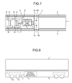
- FIG. 8 is a schematic side view illustrating a configuration of a vehicle driving apparatus that does not include a ventilating duct.
- Fig. 9 is a schematic plan view illustrating the configuration of the vehicle driving apparatus illustrated in Fig. 8 when the bottom part of the corresponding vehicle is viewed from below.
- the constituent elements identical to those illustrated in Figs. 1 and 2 are referred to by the same reference numerals.
- the totally enclosed main motor 5 draws in the outside air around the installation location from the suction inlet 58 and then exhausts high temperature air having a higher temperature than the temperature at the time of drawing in the outside air. Since the side covers 8 are disposed at the underfloor sides of the vehicle body 1, the high temperature air expelled by the totally enclosed main motor 5 tends to stagnate in the region surrounded by the side covers 8. Because of this, the totally enclosed main motor 5 happens to draw in the high temperature air from around the installation location and guide the drawn-in air in the outside air ventilating flue 55.
- the cooling wind from the outside of the vehicle is supplied to the totally enclosed main motor 5 via the ventilating duct 9. That is, the outside air is drawn in by effectively utilizing the already-established features of the totally enclosed main motor 5.
- a vehicle heat transfer apparatus disclosed in Patent Literature 2 utilizes the vehicle running wind generated when the vehicle is running as the cooling wind.
- the air can be drawn in by using the outer fan 57 even if it is not possible to obtain sufficient vehicle running wind when the vehicle slows down or when the main motor is operating after the vehicle comes to a halt.
- Patent Literature 2 is to perform cooling of an electric equipment such as a transformer or a reactor. This object is different from the object of the present embodiment, which is to perform cooling of a totally enclosed main motor.
- the suction inlet 58 and the exhaust outlet 59 provided on the totally enclosed main motor 5 are sufficiently spaced apart. More particularly, the exhaust outlet 59 is placed on the side at which the chassis 2 is connected to the totally enclosed main motor 5; while the suction inlet 58 is placed on the opposite side of the side at which the chassis 2 is connected to the totally enclosed main motor 5. Since the inlet side and the exhaust side are sufficiently spaced apart, the inlet side is not easily affected by the heat of the exhaust air. That contributes in enhancing the cooling efficiency. Moreover, such an arrangement also facilitates easy installation of the ventilating duct 9.
- the ventilating duct 9 lies perpendicular with respect to the side covers 8 at the opening 10. Consequently, the air entering into the ventilating duct 9 from the opening 10 flows perpendicular with respect to the side covers 8.
- Such a configuration is feasible because of the abovementioned feature of drawing in the cooling wind without having to use the vehicle running wind.
- the ventilating duct 9 at a slant with respect to the side cover 8.
- the length of the ventilating duct 9 also decreases thereby enabling achieving cost reduction.
- identical to the conventional configuration it is of course possible to dispose the ventilating duct 9 at a slant with respect to the side covers 8.
- the dust collecting filter 17 is disposed at the opening 10, the dust contained in the air from the outside of the vehicle is prevented from entering into the ventilating duct 9. Consequently, the outside air ventilating flue 55 is also saved from the problem of the dust entering therein. This makes it easier to perform maintenance of the totally enclosed main motor 5.
- the connecting portion 11 provided between the suction inlet 58 and the ventilating duct 9 has retractility and flexibility, it is possible to absorb the vibrations or movement generated along with the running of the vehicle. That enhances the connection reliability between the totally enclosed main motor 5 and the ventilating duct 9.
- the totally enclosed main motor 5 is disposed outside the frame of the chassis 2. This eliminates the dimensional constraints regulated by the chassis 2 while installing the totally enclosed main motor 5. Thus, it is possible to dispose the totally enclosed main motor 5 of a high capacity. That is, by loading the totally enclosed main motor 5 to the vehicle body portion other than the chassis 2, it becomes possible to secure sufficient space and thus increase the capacity of the totally enclosed main motor 5.
- Fig. 10 is a plan view illustrating a configuration of a conventional vehicle driving apparatus.
- main motors 101a and 101b are disposed in a diagonal manner on a chassis frame 104.
- axles 105a and 105b are disposed on the chassis frame 104.
- a wheel 106 is impactedly fixed to both ends of each of the axles 105a and 105b.
- a gear device 102a is connected to the axle 105a, while a gear device 102b is connected to the axle 105b.
- the rotating shaft of the main motor 101a and the pinion shaft of the gear device 102a are flexibly coupled by a gear-type flexible coupling 103a.
- the rotating shaft of the main motor 101b and the pinion shaft of the gear device 102b are flexibly coupled by a gear-type flexible coupling 103b.
- the rotating shafts of the main motors 101a and 101b lie parallel to the axles 105a and 105b.
- the shaft 6 Since the totally enclosed main motor 5 is disposed outside the frame of the chassis 2, the shaft 6 is disposed to connect the totally enclosed main motor 5 to the axle 3a. In addition to its primary function of transmitting the rotary drive force of the totally enclosed main motor 5 to the axle 3a, the shaft 6 has good heat conductivity because of its metallic material. Thus, by helping the heat to release from the totally enclosed main motor 5, the shaft 6 contributes to the cooling effect. This enables achieving enhancement in the cooling efficiency of the totally enclosed main motor 5.
- Fig. 5 is a schematic plan view illustrating a configuration of the vehicle driving apparatus according to the present embodiment when the bottom part of the corresponding vehicle is viewed from below.
- the structure of a ventilating duct 19 is different from the structure of the ventilating duct 9 in the first embodiment.
- the constituent elements identical to those illustrated in Fig. 2 are referred to by the same reference numerals and the detailed description thereof is omitted.
- the ventilating duct 19 is a T-shaped duct having three open ends. One of the three open ends is connected to the suction inlet 58 of the totally enclosed main motor 5. One of the remaining two open ends is connected to an opening 18a that is formed on the side covers 8 disposed at one side of the vehicle, while the other of the remaining two open ends is connected to an opening 18b that is formed on the side covers 8 disposed at the other side of the vehicle. In this way, in the present embodiment, the openings 18a and 18b are formed on the side covers 8 that are disposed at the mutually opposite sides. Moreover, a dust collecting filter 20a is disposed at the opening 18a and a dust collecting filter 20b is disposed at the opening 18b.
- the present embodiment for example, even if the opening 18a formed on one of the side covers 8 gets clogged due to foreign particles, it is possible to use the other opening 18b to draw in the air from the outside of the vehicle. Thus, it becomes possible to obtain a stable flow of the cooling wind through the ventilating duct 19.
- the number of openings is not limited to two and it is generally possible to form more than two openings.
- the configuration, the behavior, and the effect of the present embodiment are identical to that of the first embodiment.
- Fig. 6 is a schematic plan view illustrating a configuration of the vehicle driving apparatus according to the present embodiment when the bottom part of the corresponding vehicle is viewed from below.
- Fig. 7 is a schematic plan view illustrating an exemplary modification of the configuration of the vehicle driving apparatus according to the present embodiment when the bottom part of the corresponding vehicle is viewed from below.
- the constituent elements identical to those illustrated in Fig. 2 are referred to by the same reference numerals and the detailed description thereof is omitted.
- a ventilating duct 30 for exhaust air is disposed in the configuration according to the second embodiment illustrated in Fig. 5 . More particularly, one end of the ventilating duct 30 is connected to the exhaust outlet 59 of the totally enclosed main motor 5 and the other end of the ventilating duct 30 is connected to an opening 31 formed on the side covers 8.
- the ventilating duct 30 for exhaust air Because of the ventilating duct 30 for exhaust air, the high temperature air exhausted from the outside air ventilating flue 55 of the totally enclosed main motor 5 can be reliable exhausted to the outside of the vehicle. That is, the air having its temperature increased due to the release of heat in the totally enclosed main motor 5 does not stagnate around the totally enclosed main motor 5. This enables achieving further enhancement in the cooling efficiency.
- the suction inlet 58 and the exhaust outlet 59 are sufficiently spaced apart.
- the exhaust outlet 59 is placed on the side of the chassis 2 to which the totally enclosed main motor 5 is connected, while the suction inlet 58 is placed on the opposite side of the chassis 2 to which the totally enclosed main motor 5 is connected.
- the ventilating duct 30 for exhaust air is connected to the exhaust outlet 59.
- the ventilating duct 30 elongates along the connecting direction, then bends in a right angle with respect to the running direction of the vehicle, and connects to the opening 31 formed on the side covers 8. Therefore, the position of the opening 31 used in exhaust air is sufficiently spaced apart from the positions of the openings 18a and 18b used in suction air.
- the inlet side is not easily affected by the heat of the exhaust air.
- the exhaust air via the ventilating duct 30 is performed by the operation of the outer fan 57 that is disposed in the outside air ventilating flue 55 of the totally enclosed main motor 5. This eliminates the need of newly disposing a device for producing a forced blast. Moreover, there is also no need of using the vehicle running wind as is the case in the conventional technology.
- the shape of the ventilating duct 30 for exhaust air is not limited to the shape according to the present embodiment and can be configured in, for example, T shape that is identical to the ventilating duct 19 used in suction air.
- the connecting portion of the ventilating duct 30 with respect to the totally enclosed main motor 5 can be configured to have retractility and flexibility in an identical manner to the connecting portion 11.
- the configuration, the behavior, and the effect of the present embodiment are identical to that of the second embodiment.
- the present invention is suitable in a high-speed vehicle in which side covers are disposed at the sides of the bottom part of the vehicle.
Landscapes
- Engineering & Computer Science (AREA)
- Transportation (AREA)
- Mechanical Engineering (AREA)
- Chemical & Material Sciences (AREA)
- Combustion & Propulsion (AREA)
- Automation & Control Theory (AREA)
- Motor Or Generator Cooling System (AREA)
- Electric Propulsion And Braking For Vehicles (AREA)
- Seal Device For Vehicle (AREA)
- Treatment Of Sludge (AREA)
- Control Of Multiple Motors (AREA)
- Arrangement Or Mounting Of Propulsion Units For Vehicles (AREA)
- Body Structure For Vehicles (AREA)
Applications Claiming Priority (1)
| Application Number | Priority Date | Filing Date | Title |
|---|---|---|---|
| PCT/JP2007/067607 WO2009034607A1 (ja) | 2007-09-10 | 2007-09-10 | 車両用駆動装置 |
Publications (3)
| Publication Number | Publication Date |
|---|---|
| EP2186704A1 true EP2186704A1 (de) | 2010-05-19 |
| EP2186704A4 EP2186704A4 (de) | 2010-10-27 |
| EP2186704B1 EP2186704B1 (de) | 2011-11-16 |
Family
ID=40451632
Family Applications (1)
| Application Number | Title | Priority Date | Filing Date |
|---|---|---|---|
| EP07849898A Active EP2186704B1 (de) | 2007-09-10 | 2007-09-10 | Antriebsvorrichtung für fahrzeug |
Country Status (7)
| Country | Link |
|---|---|
| US (1) | US8448732B2 (de) |
| EP (1) | EP2186704B1 (de) |
| JP (1) | JP4503099B2 (de) |
| CN (1) | CN101795922B (de) |
| AT (1) | ATE533681T1 (de) |
| ES (1) | ES2377832T3 (de) |
| WO (1) | WO2009034607A1 (de) |
Cited By (1)
| Publication number | Priority date | Publication date | Assignee | Title |
|---|---|---|---|---|
| FR3016197A1 (fr) * | 2014-01-09 | 2015-07-10 | Technofan | Plaque froide autonome pour refroidissement des composants electroniques d'un ventilateur electrique |
Families Citing this family (6)
| Publication number | Priority date | Publication date | Assignee | Title |
|---|---|---|---|---|
| EP2833080A1 (de) * | 2013-07-29 | 2015-02-04 | ABB Technology AG | Lüftungseinlassmodul, Lüftungsvorrichtung und Verfahren zum Betreiben einer Lüftungsvorrichtung |
| FR3032568B1 (fr) * | 2015-02-06 | 2018-10-26 | Alstom Transport Technologies | Moteur electrique avec radiateur exterieur et deux circuits de refroidissement separes |
| JP2018064384A (ja) * | 2016-10-13 | 2018-04-19 | 東芝三菱電機産業システム株式会社 | 全閉外扇形回転電機 |
| JP7057313B2 (ja) * | 2019-04-09 | 2022-04-19 | ファナック株式会社 | 冷却機を含む電動機を備える工作機械 |
| US12231006B2 (en) * | 2020-01-27 | 2025-02-18 | Mitsubishi Electric Corporation | Drive control device for electric vehicle |
| US12489342B2 (en) | 2021-03-08 | 2025-12-02 | Mitsubishi Electric Corporation | Electric motor |
Family Cites Families (30)
| Publication number | Priority date | Publication date | Assignee | Title |
|---|---|---|---|---|
| US1481888A (en) * | 1920-04-07 | 1924-01-29 | Westinghouse Electric & Mfg Co | Air conductor for railway motors |
| JPS54167904U (de) * | 1978-05-18 | 1979-11-27 | ||
| US4348604A (en) * | 1980-06-13 | 1982-09-07 | General Dynamics Corp. | Totally enclosed air cooled electrical machines |
| JPS58129194A (ja) * | 1982-01-29 | 1983-08-02 | Hitachi Ltd | 車輛用熱交換装置 |
| JPS6164567A (ja) | 1984-09-05 | 1986-04-02 | Japanese National Railways<Jnr> | 高速電気車両の発電ブレ−キ用抵抗器の冷却装置 |
| JPS61115767A (ja) | 1984-11-12 | 1986-06-03 | 財団法人鉄道総合技術研究所 | ボデイマウント式の電車の主回路用電気機器の冷却装置 |
| US4908538A (en) * | 1989-02-28 | 1990-03-13 | Geberth John Daniel Jun | Totally enclosed electric motor |
| JPH05229430A (ja) | 1992-02-19 | 1993-09-07 | Hitachi Ltd | 車 両 |
| JPH06239229A (ja) | 1993-02-19 | 1994-08-30 | Hitachi Ltd | 車両用空調装置及びその制御方法 |
| US5381737A (en) * | 1993-05-25 | 1995-01-17 | Trenary; Bryant | Rail truck suspended car transit vehicles |
| JP3361575B2 (ja) | 1993-09-27 | 2003-01-07 | 株式会社日立製作所 | 車両用機器冷却装置 |
| DE9415770U1 (de) * | 1994-09-30 | 1994-12-15 | ABB Henschel AG, 13509 Berlin | Schienengebundenes Dieseltriebfahrzeug |
| JPH08192654A (ja) | 1995-01-17 | 1996-07-30 | Toshiba Transport Eng Kk | 車両用半導体制御装置 |
| WO1996037397A1 (de) | 1995-05-24 | 1996-11-28 | Krauss-Maffei Verkehrstechnik Gmbh | Angetriebenes laufwerk für schienenfahrzeuge mit spurwechseleinrichtung |
| US5789833A (en) * | 1995-11-24 | 1998-08-04 | Kabushiki Kaisha Toshiba | Totally-enclosed traction motor for electric railcar |
| JP3504052B2 (ja) | 1996-02-14 | 2004-03-08 | 株式会社日立製作所 | 電気車用電力変換装置 |
| JPH10157617A (ja) | 1996-12-03 | 1998-06-16 | Hitachi Ltd | 車両用制御装置 |
| JP3373446B2 (ja) | 1998-11-24 | 2003-02-04 | 三菱電機株式会社 | 車載用冷却装置 |
| US6700235B1 (en) * | 1999-11-02 | 2004-03-02 | Franklin Electric Co. | Enhanced cooling apparatus and method for rotating machinery |
| DE10118219A1 (de) * | 2001-04-12 | 2002-10-17 | Daimlerchrysler Rail Systems | Schienentriebfahrzeug mit einer Antriebsvorrichtung und geräuschdämmenden Mitteln |
| JP3959248B2 (ja) | 2001-08-03 | 2007-08-15 | 東海旅客鉄道株式会社 | 高速鉄道車両用電力変換装置 |
| JP2003088045A (ja) * | 2001-09-12 | 2003-03-20 | Toshiba Transport Eng Inc | 全閉外扇形電動機 |
| JP3894114B2 (ja) * | 2002-12-10 | 2007-03-14 | 三菱電機株式会社 | 全閉形電動機 |
| JP4549086B2 (ja) | 2004-03-23 | 2010-09-22 | 東日本旅客鉄道株式会社 | 鉄道車両用走行風冷却装置 |
| WO2006038515A1 (ja) * | 2004-10-01 | 2006-04-13 | Kabushiki Kaisha Toshiba | 車両駆動用全閉型主電動機 |
| US7644792B2 (en) * | 2006-01-06 | 2010-01-12 | Hamilton Sundstrand | Motor cooling system |
| JP2007306741A (ja) * | 2006-05-12 | 2007-11-22 | Toshiba Corp | 制御装置一体型電動機 |
| GB2448548A (en) * | 2007-04-21 | 2008-10-22 | Converteam Ltd | Vortex cleaning of air intake of electrical machine |
| US8006626B2 (en) * | 2007-05-07 | 2011-08-30 | General Electric Company | System and method for cooling a battery |
| JP2009161062A (ja) * | 2008-01-08 | 2009-07-23 | Calsonic Kansei Corp | 発熱体の冷却装置 |
-
2007
- 2007-09-10 EP EP07849898A patent/EP2186704B1/de active Active
- 2007-09-10 ES ES07849898T patent/ES2377832T3/es active Active
- 2007-09-10 AT AT07849898T patent/ATE533681T1/de active
- 2007-09-10 WO PCT/JP2007/067607 patent/WO2009034607A1/ja not_active Ceased
- 2007-09-10 US US12/672,313 patent/US8448732B2/en not_active Expired - Fee Related
- 2007-09-10 CN CN2007801005797A patent/CN101795922B/zh active Active
- 2007-09-10 JP JP2009531991A patent/JP4503099B2/ja active Active
Cited By (3)
| Publication number | Priority date | Publication date | Assignee | Title |
|---|---|---|---|---|
| FR3016197A1 (fr) * | 2014-01-09 | 2015-07-10 | Technofan | Plaque froide autonome pour refroidissement des composants electroniques d'un ventilateur electrique |
| EP2894351A1 (de) * | 2014-01-09 | 2015-07-15 | Technofan | Autonome Kühlplatte zum Abkühlen der elektronischen Komponenten eines elektrischen Ventilators |
| US10018200B2 (en) | 2014-01-09 | 2018-07-10 | Technofan | Self-contained cold plate for cooling electronic components of an electric fan |
Also Published As
| Publication number | Publication date |
|---|---|
| ES2377832T3 (es) | 2012-04-02 |
| JP4503099B2 (ja) | 2010-07-14 |
| ATE533681T1 (de) | 2011-12-15 |
| WO2009034607A1 (ja) | 2009-03-19 |
| CN101795922B (zh) | 2013-12-04 |
| CN101795922A (zh) | 2010-08-04 |
| US20110315460A1 (en) | 2011-12-29 |
| EP2186704B1 (de) | 2011-11-16 |
| EP2186704A4 (de) | 2010-10-27 |
| US8448732B2 (en) | 2013-05-28 |
| JPWO2009034607A1 (ja) | 2010-12-16 |
Similar Documents
| Publication | Publication Date | Title |
|---|---|---|
| US8448732B2 (en) | Vehicle driving apparatus | |
| TWI410027B (zh) | A fully enclosed main motor for a vehicle | |
| JP2007306741A (ja) | 制御装置一体型電動機 | |
| CN111902327B (zh) | 轨道车辆的转向架 | |
| JP5889512B2 (ja) | 車両駆動装置 | |
| KR20010085527A (ko) | 전폐형 구동 전동기 | |
| WO2012031966A1 (de) | Fahrmotor mit kühlung | |
| JP4772298B2 (ja) | 車両駆動用全閉型電動機 | |
| CN210669792U (zh) | 马达单元 | |
| JP2004194498A (ja) | 全閉外扇冷却型電動機 | |
| CN221834368U (zh) | 一种电动机组合驱动关节模组 | |
| JP4939905B2 (ja) | 車両用駆動装置 | |
| DE112020006619T5 (de) | Antriebssteuerungseinrichtung für ein elektrofahrzeug | |
| JP2008125172A (ja) | 車両用駆動装置 | |
| JP2012017103A (ja) | 電気車制御装置 | |
| JP2018039316A (ja) | 冷却装置およびそれを搭載した台車並びに鉄道車両 | |
| JP2010120483A (ja) | 鉄道車両 | |
| JP4891656B2 (ja) | 車両用全閉形電動機 | |
| CN216564682U (zh) | 一种全封闭双循环风冷电机结构 | |
| JP2008086164A (ja) | 全閉外扇形電動機 | |
| JP3796436B2 (ja) | 車両駆動用電動機 | |
| JP4180974B2 (ja) | 車両駆動用全閉自冷形電動機及び該電動機に備わる冷却器の製造方法 | |
| CN209908796U (zh) | 一种离心风机 | |
| KR102890283B1 (ko) | 방열성능 향상을 위한 인휠 모터용 씰링장치 | |
| US11535281B2 (en) | Drive system for a rail vehicle, rail vehicle having the drive system and methods for the forward movement of a rail vehicle |
Legal Events
| Date | Code | Title | Description |
|---|---|---|---|
| PUAI | Public reference made under article 153(3) epc to a published international application that has entered the european phase |
Free format text: ORIGINAL CODE: 0009012 |
|
| 17P | Request for examination filed |
Effective date: 20100218 |
|
| AK | Designated contracting states |
Kind code of ref document: A1 Designated state(s): AT BE BG CH CY CZ DE DK EE ES FI FR GB GR HU IE IS IT LI LT LU LV MC MT NL PL PT RO SE SI SK TR |
|
| AX | Request for extension of the european patent |
Extension state: AL BA HR MK RS |
|
| A4 | Supplementary search report drawn up and despatched |
Effective date: 20100924 |
|
| DAX | Request for extension of the european patent (deleted) | ||
| GRAP | Despatch of communication of intention to grant a patent |
Free format text: ORIGINAL CODE: EPIDOSNIGR1 |
|
| RIC1 | Information provided on ipc code assigned before grant |
Ipc: B61C 3/00 20060101AFI20110523BHEP Ipc: B61C 9/52 20060101ALI20110523BHEP |
|
| GRAS | Grant fee paid |
Free format text: ORIGINAL CODE: EPIDOSNIGR3 |
|
| GRAA | (expected) grant |
Free format text: ORIGINAL CODE: 0009210 |
|
| AK | Designated contracting states |
Kind code of ref document: B1 Designated state(s): AT BE BG CH CY CZ DE DK EE ES FI FR GB GR HU IE IS IT LI LT LU LV MC MT NL PL PT RO SE SI SK TR |
|
| REG | Reference to a national code |
Ref country code: GB Ref legal event code: FG4D |
|
| REG | Reference to a national code |
Ref country code: CH Ref legal event code: EP |
|
| REG | Reference to a national code |
Ref country code: IE Ref legal event code: FG4D |
|
| REG | Reference to a national code |
Ref country code: DE Ref legal event code: R096 Ref document number: 602007018821 Country of ref document: DE Effective date: 20120112 |
|
| REG | Reference to a national code |
Ref country code: NL Ref legal event code: VDEP Effective date: 20111116 |
|
| REG | Reference to a national code |
Ref country code: ES Ref legal event code: FG2A Ref document number: 2377832 Country of ref document: ES Kind code of ref document: T3 Effective date: 20120402 |
|
| LTIE | Lt: invalidation of european patent or patent extension |
Effective date: 20111116 |
|
| PG25 | Lapsed in a contracting state [announced via postgrant information from national office to epo] |
Ref country code: LT Free format text: LAPSE BECAUSE OF FAILURE TO SUBMIT A TRANSLATION OF THE DESCRIPTION OR TO PAY THE FEE WITHIN THE PRESCRIBED TIME-LIMIT Effective date: 20111116 Ref country code: IS Free format text: LAPSE BECAUSE OF FAILURE TO SUBMIT A TRANSLATION OF THE DESCRIPTION OR TO PAY THE FEE WITHIN THE PRESCRIBED TIME-LIMIT Effective date: 20120316 |
|
| PG25 | Lapsed in a contracting state [announced via postgrant information from national office to epo] |
Ref country code: BE Free format text: LAPSE BECAUSE OF FAILURE TO SUBMIT A TRANSLATION OF THE DESCRIPTION OR TO PAY THE FEE WITHIN THE PRESCRIBED TIME-LIMIT Effective date: 20111116 Ref country code: LV Free format text: LAPSE BECAUSE OF FAILURE TO SUBMIT A TRANSLATION OF THE DESCRIPTION OR TO PAY THE FEE WITHIN THE PRESCRIBED TIME-LIMIT Effective date: 20111116 Ref country code: SI Free format text: LAPSE BECAUSE OF FAILURE TO SUBMIT A TRANSLATION OF THE DESCRIPTION OR TO PAY THE FEE WITHIN THE PRESCRIBED TIME-LIMIT Effective date: 20111116 Ref country code: PT Free format text: LAPSE BECAUSE OF FAILURE TO SUBMIT A TRANSLATION OF THE DESCRIPTION OR TO PAY THE FEE WITHIN THE PRESCRIBED TIME-LIMIT Effective date: 20120316 Ref country code: NL Free format text: LAPSE BECAUSE OF FAILURE TO SUBMIT A TRANSLATION OF THE DESCRIPTION OR TO PAY THE FEE WITHIN THE PRESCRIBED TIME-LIMIT Effective date: 20111116 Ref country code: GR Free format text: LAPSE BECAUSE OF FAILURE TO SUBMIT A TRANSLATION OF THE DESCRIPTION OR TO PAY THE FEE WITHIN THE PRESCRIBED TIME-LIMIT Effective date: 20120217 Ref country code: PL Free format text: LAPSE BECAUSE OF FAILURE TO SUBMIT A TRANSLATION OF THE DESCRIPTION OR TO PAY THE FEE WITHIN THE PRESCRIBED TIME-LIMIT Effective date: 20111116 Ref country code: SE Free format text: LAPSE BECAUSE OF FAILURE TO SUBMIT A TRANSLATION OF THE DESCRIPTION OR TO PAY THE FEE WITHIN THE PRESCRIBED TIME-LIMIT Effective date: 20111116 |
|
| PG25 | Lapsed in a contracting state [announced via postgrant information from national office to epo] |
Ref country code: CY Free format text: LAPSE BECAUSE OF FAILURE TO SUBMIT A TRANSLATION OF THE DESCRIPTION OR TO PAY THE FEE WITHIN THE PRESCRIBED TIME-LIMIT Effective date: 20111116 |
|
| PG25 | Lapsed in a contracting state [announced via postgrant information from national office to epo] |
Ref country code: DK Free format text: LAPSE BECAUSE OF FAILURE TO SUBMIT A TRANSLATION OF THE DESCRIPTION OR TO PAY THE FEE WITHIN THE PRESCRIBED TIME-LIMIT Effective date: 20111116 Ref country code: SK Free format text: LAPSE BECAUSE OF FAILURE TO SUBMIT A TRANSLATION OF THE DESCRIPTION OR TO PAY THE FEE WITHIN THE PRESCRIBED TIME-LIMIT Effective date: 20111116 Ref country code: EE Free format text: LAPSE BECAUSE OF FAILURE TO SUBMIT A TRANSLATION OF THE DESCRIPTION OR TO PAY THE FEE WITHIN THE PRESCRIBED TIME-LIMIT Effective date: 20111116 Ref country code: BG Free format text: LAPSE BECAUSE OF FAILURE TO SUBMIT A TRANSLATION OF THE DESCRIPTION OR TO PAY THE FEE WITHIN THE PRESCRIBED TIME-LIMIT Effective date: 20120216 Ref country code: CZ Free format text: LAPSE BECAUSE OF FAILURE TO SUBMIT A TRANSLATION OF THE DESCRIPTION OR TO PAY THE FEE WITHIN THE PRESCRIBED TIME-LIMIT Effective date: 20111116 |
|
| PG25 | Lapsed in a contracting state [announced via postgrant information from national office to epo] |
Ref country code: RO Free format text: LAPSE BECAUSE OF FAILURE TO SUBMIT A TRANSLATION OF THE DESCRIPTION OR TO PAY THE FEE WITHIN THE PRESCRIBED TIME-LIMIT Effective date: 20111116 |
|
| REG | Reference to a national code |
Ref country code: AT Ref legal event code: MK05 Ref document number: 533681 Country of ref document: AT Kind code of ref document: T Effective date: 20111116 |
|
| PLBE | No opposition filed within time limit |
Free format text: ORIGINAL CODE: 0009261 |
|
| STAA | Information on the status of an ep patent application or granted ep patent |
Free format text: STATUS: NO OPPOSITION FILED WITHIN TIME LIMIT |
|
| 26N | No opposition filed |
Effective date: 20120817 |
|
| REG | Reference to a national code |
Ref country code: DE Ref legal event code: R097 Ref document number: 602007018821 Country of ref document: DE Effective date: 20120817 |
|
| PG25 | Lapsed in a contracting state [announced via postgrant information from national office to epo] |
Ref country code: AT Free format text: LAPSE BECAUSE OF FAILURE TO SUBMIT A TRANSLATION OF THE DESCRIPTION OR TO PAY THE FEE WITHIN THE PRESCRIBED TIME-LIMIT Effective date: 20111116 |
|
| PG25 | Lapsed in a contracting state [announced via postgrant information from national office to epo] |
Ref country code: MC Free format text: LAPSE BECAUSE OF NON-PAYMENT OF DUE FEES Effective date: 20120930 |
|
| REG | Reference to a national code |
Ref country code: CH Ref legal event code: PL |
|
| GBPC | Gb: european patent ceased through non-payment of renewal fee |
Effective date: 20120910 |
|
| REG | Reference to a national code |
Ref country code: IE Ref legal event code: MM4A |
|
| PG25 | Lapsed in a contracting state [announced via postgrant information from national office to epo] |
Ref country code: FI Free format text: LAPSE BECAUSE OF FAILURE TO SUBMIT A TRANSLATION OF THE DESCRIPTION OR TO PAY THE FEE WITHIN THE PRESCRIBED TIME-LIMIT Effective date: 20111116 |
|
| PG25 | Lapsed in a contracting state [announced via postgrant information from national office to epo] |
Ref country code: LI Free format text: LAPSE BECAUSE OF NON-PAYMENT OF DUE FEES Effective date: 20120930 Ref country code: CH Free format text: LAPSE BECAUSE OF NON-PAYMENT OF DUE FEES Effective date: 20120930 Ref country code: IE Free format text: LAPSE BECAUSE OF NON-PAYMENT OF DUE FEES Effective date: 20120910 Ref country code: GB Free format text: LAPSE BECAUSE OF NON-PAYMENT OF DUE FEES Effective date: 20120910 |
|
| PG25 | Lapsed in a contracting state [announced via postgrant information from national office to epo] |
Ref country code: MT Free format text: LAPSE BECAUSE OF FAILURE TO SUBMIT A TRANSLATION OF THE DESCRIPTION OR TO PAY THE FEE WITHIN THE PRESCRIBED TIME-LIMIT Effective date: 20111116 |
|
| REG | Reference to a national code |
Ref country code: ES Ref legal event code: GC2A Effective date: 20140416 |
|
| PG25 | Lapsed in a contracting state [announced via postgrant information from national office to epo] |
Ref country code: TR Free format text: LAPSE BECAUSE OF FAILURE TO SUBMIT A TRANSLATION OF THE DESCRIPTION OR TO PAY THE FEE WITHIN THE PRESCRIBED TIME-LIMIT Effective date: 20111116 |
|
| REG | Reference to a national code |
Ref country code: DE Ref legal event code: R084 Ref document number: 602007018821 Country of ref document: DE Effective date: 20140326 |
|
| PG25 | Lapsed in a contracting state [announced via postgrant information from national office to epo] |
Ref country code: LU Free format text: LAPSE BECAUSE OF NON-PAYMENT OF DUE FEES Effective date: 20120910 |
|
| PG25 | Lapsed in a contracting state [announced via postgrant information from national office to epo] |
Ref country code: HU Free format text: LAPSE BECAUSE OF FAILURE TO SUBMIT A TRANSLATION OF THE DESCRIPTION OR TO PAY THE FEE WITHIN THE PRESCRIBED TIME-LIMIT Effective date: 20070910 |
|
| REG | Reference to a national code |
Ref country code: FR Ref legal event code: PLFP Year of fee payment: 10 |
|
| REG | Reference to a national code |
Ref country code: FR Ref legal event code: PLFP Year of fee payment: 11 |
|
| REG | Reference to a national code |
Ref country code: FR Ref legal event code: PLFP Year of fee payment: 12 |
|
| PGFP | Annual fee paid to national office [announced via postgrant information from national office to epo] |
Ref country code: FR Payment date: 20180813 Year of fee payment: 12 |
|
| PG25 | Lapsed in a contracting state [announced via postgrant information from national office to epo] |
Ref country code: FR Free format text: LAPSE BECAUSE OF NON-PAYMENT OF DUE FEES Effective date: 20190930 |
|
| PGFP | Annual fee paid to national office [announced via postgrant information from national office to epo] |
Ref country code: IT Payment date: 20200812 Year of fee payment: 14 |
|
| PGFP | Annual fee paid to national office [announced via postgrant information from national office to epo] |
Ref country code: ES Payment date: 20211001 Year of fee payment: 15 |
|
| PG25 | Lapsed in a contracting state [announced via postgrant information from national office to epo] |
Ref country code: IT Free format text: LAPSE BECAUSE OF NON-PAYMENT OF DUE FEES Effective date: 20210910 |
|
| P01 | Opt-out of the competence of the unified patent court (upc) registered |
Effective date: 20230512 |
|
| REG | Reference to a national code |
Ref country code: ES Ref legal event code: FD2A Effective date: 20231027 |
|
| PG25 | Lapsed in a contracting state [announced via postgrant information from national office to epo] |
Ref country code: ES Free format text: LAPSE BECAUSE OF NON-PAYMENT OF DUE FEES Effective date: 20220911 |
|
| PG25 | Lapsed in a contracting state [announced via postgrant information from national office to epo] |
Ref country code: ES Free format text: LAPSE BECAUSE OF NON-PAYMENT OF DUE FEES Effective date: 20220911 |
|
| PGFP | Annual fee paid to national office [announced via postgrant information from national office to epo] |
Ref country code: DE Payment date: 20250730 Year of fee payment: 19 |