EP2186992A2 - Dispositif antichute et fermeture d'ouverture dotée d'un dispositif antichute - Google Patents
Dispositif antichute et fermeture d'ouverture dotée d'un dispositif antichute Download PDFInfo
- Publication number
- EP2186992A2 EP2186992A2 EP09010872A EP09010872A EP2186992A2 EP 2186992 A2 EP2186992 A2 EP 2186992A2 EP 09010872 A EP09010872 A EP 09010872A EP 09010872 A EP09010872 A EP 09010872A EP 2186992 A2 EP2186992 A2 EP 2186992A2
- Authority
- EP
- European Patent Office
- Prior art keywords
- mounting bracket
- cage
- safety
- catching
- safety gear
- Prior art date
- Legal status (The legal status is an assumption and is not a legal conclusion. Google has not performed a legal analysis and makes no representation as to the accuracy of the status listed.)
- Withdrawn
Links
- 230000000903 blocking effect Effects 0.000 claims description 22
- 238000004804 winding Methods 0.000 claims description 19
- 238000005096 rolling process Methods 0.000 claims description 7
- 229910000831 Steel Inorganic materials 0.000 claims description 4
- 239000010959 steel Substances 0.000 claims description 4
- 230000015572 biosynthetic process Effects 0.000 claims description 3
- 230000004888 barrier function Effects 0.000 abstract 3
- 239000000463 material Substances 0.000 description 6
- 238000000465 moulding Methods 0.000 description 6
- 238000013016 damping Methods 0.000 description 4
- 238000004519 manufacturing process Methods 0.000 description 4
- 230000000694 effects Effects 0.000 description 3
- 239000000314 lubricant Substances 0.000 description 2
- 239000002184 metal Substances 0.000 description 2
- 229910052751 metal Inorganic materials 0.000 description 2
- 238000000034 method Methods 0.000 description 2
- 239000007787 solid Substances 0.000 description 2
- 229910001369 Brass Inorganic materials 0.000 description 1
- RYGMFSIKBFXOCR-UHFFFAOYSA-N Copper Chemical compound [Cu] RYGMFSIKBFXOCR-UHFFFAOYSA-N 0.000 description 1
- 230000001133 acceleration Effects 0.000 description 1
- 230000002238 attenuated effect Effects 0.000 description 1
- 238000005452 bending Methods 0.000 description 1
- 239000010951 brass Substances 0.000 description 1
- 238000010276 construction Methods 0.000 description 1
- 229910052802 copper Inorganic materials 0.000 description 1
- 239000010949 copper Substances 0.000 description 1
- 230000001419 dependent effect Effects 0.000 description 1
- 238000009434 installation Methods 0.000 description 1
- 239000010970 precious metal Substances 0.000 description 1
- 238000004080 punching Methods 0.000 description 1
- 239000002699 waste material Substances 0.000 description 1
- 239000013585 weight reducing agent Substances 0.000 description 1
Images


Classifications
-
- E—FIXED CONSTRUCTIONS
- E06—DOORS, WINDOWS, SHUTTERS, OR ROLLER BLINDS IN GENERAL; LADDERS
- E06B—FIXED OR MOVABLE CLOSURES FOR OPENINGS IN BUILDINGS, VEHICLES, FENCES OR LIKE ENCLOSURES IN GENERAL, e.g. DOORS, WINDOWS, BLINDS, GATES
- E06B9/00—Screening or protective devices for wall or similar openings, with or without operating or securing mechanisms; Closures of similar construction
- E06B9/56—Operating, guiding or securing devices or arrangements for roll-type closures; Spring drums; Tape drums; Counterweighting arrangements therefor
- E06B9/80—Safety measures against dropping or unauthorised opening; Braking or immobilising devices; Devices for limiting unrolling
- E06B9/82—Safety measures against dropping or unauthorised opening; Braking or immobilising devices; Devices for limiting unrolling automatic
- E06B9/84—Safety measures against dropping or unauthorised opening; Braking or immobilising devices; Devices for limiting unrolling automatic against dropping
-
- E—FIXED CONSTRUCTIONS
- E06—DOORS, WINDOWS, SHUTTERS, OR ROLLER BLINDS IN GENERAL; LADDERS
- E06B—FIXED OR MOVABLE CLOSURES FOR OPENINGS IN BUILDINGS, VEHICLES, FENCES OR LIKE ENCLOSURES IN GENERAL, e.g. DOORS, WINDOWS, BLINDS, GATES
- E06B9/00—Screening or protective devices for wall or similar openings, with or without operating or securing mechanisms; Closures of similar construction
- E06B9/02—Shutters, movable grilles, or other safety closing devices, e.g. against burglary
- E06B9/08—Roll-type closures
- E06B9/11—Roller shutters
- E06B9/17—Parts or details of roller shutters, e.g. suspension devices, shutter boxes, wicket doors, ventilation openings
- E06B9/174—Bearings specially adapted therefor
Definitions
- the present invention relates to safety gear for securing wound on winding shafts opening closures with an unwanted and / or sudden rolling movement can be prevented by centrifugal force. Furthermore, the invention relates to an opening closure with safety gear.
- Such rotational speed-dependent rotary catch devices are used as a security element for shutters, roller shutters or rolling grilles.
- the safety gear on a basic housing, a cage and a cage arranged in the ratchet arranged in the ratchet locking cylinders.
- the locking cylinder are carried out at a certain limit speed is exceeded by the centrifugal force to the outside and thereby lock a further rotational movement.
- the housing or basic housing is very solid and beyond only indirectly, usually by means of another mounting or mounting bracket which engages in the large recessed in the housing Bolzenaufrich or bolt holes, for example, is attached to the wall.
- the embedded in the housing Bolzenaufrich or bolt holes are located eg in the corners of the housing of the safety gear according to DE 31 40 792 C2 , As a result, the safety gear is very difficult and expensive, because the basic housing must be worked from the solid as a rule. Consequently, the material and production costs are high.
- a safety gear having the features of claim 1.
- a safety device for securing wound on winding shafts opening statements has a mounting bracket for fastening the safety gear, and an at least partially rotatable fishing cage with a provided with at least one recess, rotatable relative to the fishing cage locking means.
- the blocking means is rotatably connected to the winding shaft and in the at least one recess of the locking means is provided at least one locking body, wherein the locking body can be activated by centrifugal force and wherein in the housing of the catching cage a first Fangklafiganschlag is formed to stop for the locking body.
- the mounting bracket has one or more fixed bearing points for direct attachment of the safety gear and a mounting bracket stop to stop for a second Fangklafiganschlag and that the fishing cage is rotatably mounted directly in the mounting bracket.
- the fixed bearing points for example, holes, bolts, screws or bolt receptacles, which serve for direct attachment of the safety gear.
- an immediate attachment is to be understood as meaning that thereby the safety gear is firmly attached to the wall or a fixed support such as a goalpost, door jamb or window frame.
- the mounting bracket is formed of a plate and / or of a steel sheet.
- sheet steel is not restrictive to the effect that only steel is considered as a material. Rather, any type of sheet metal may be used if it meets the load requirements of the mounting bracket, such as e.g. a brass, copper or precious metal sheet.
- the safety gear has two mounting bracket stops, two first Fangklafigandite and two second Fangkafiganexcellent.
- the safety gear can be used in two directions of rotation can be executed.
- the catch cage can be rotated between the stops of the mounting bracket. This rotation is used, for example, to be able to dampen the blocking effect, which is achieved by the stop of the locking body against the first Fanghanfiganschlag in a first step by allowing a muted further rotation of the fishing cage against the stop of the second Fangklafiganschlags against the stop.
- dampers or damping means can be provided. These may also include braking means or be designed as a braking means.
- the catching cage has at least one Gepurusformung that forms the first and / or second Fangklafiganschlag.
- first and second Fangharifiganschlag are formed in a common Gepatiuseausformung the safety cage, wherein the first Fanghanfiganschlag is located on the inside of the housing molding and the second Fangrithkamudschlag on the outside of the Gepatiuseausformung.
- a blocking force from the fixed bearing points of the mounting bracket to the winding shaft is conductive, the power flow of the blocking force from the bearing exclusively on mounting bracket, mounting bracket stop, formed in a common Gepatiuseausformung first and second catch body stopper, locking body and locking means on the Winding shaft is passed.
- the term exclusive power flow of the blocking force in this context is to be understood in particular such that in this case the blocking force is essentially transmitted via the blocking in the case exclusively on the abutting components of the safety gear and any forces acting in the pivot bearing in this regard should be disregarded ,
- mounting bracket stop and second Fangrithmaschinend are directly abuttable with each other. It is also understood that on the mounting bracket stop and the second Fangrithgoricht a rubber damping element can be firmly applied.
- pivot bearing between fishing cage and mounting bracket is designed as a ball or cylinder bearings.
- At least one side cover is provided for covering the catching cage, which is formed from plastic. This can save weight, material and costs.
- the side cover can be made lighter due to the design of the safety gear and the predefined power flow, since the side cover no supporting function and no large Must absorb forces. It can only serve the cover, ie to prevent eg dirt entry and / or lubricant leakage. Furthermore, it is conceivable to carry out the side cover for the front and rear as a common part. Common parts in particular have cost and quality advantages and help to reduce manufacturing, development and material costs.
- the blocking bodies are cylinders and / or balls.
- the blocking means is gear-shaped and / or star-shaped, wherein the recesses are arranged uniformly circumferentially.
- the present invention relates to an opening closure with the features of claim 15. Thereafter, it is provided that the opening conclusion, which is wound on a winding shaft, at least one safety device according to one of claims 1 to 14.
- FIG. 1 shows a perspective view of the front and back of a safety gear 10.
- the safety gear 10 has a formed from a formed sheet metal mounting bracket 20, which is a fixed bearing performing attachment 24 in the form of four diagonally arranged slots 24 for receiving fastening bolts, not shown having.
- the fastening bolts may be, for example, screws which are provided in dowelled holes e.g. can be fixed in the wall.
- the mounting bracket 20 has four fixed bearing points 24 for direct attachment of the safety gear 10.
- the safety gear 10 has a hub 15, in which the winding shaft, not shown, of a wound-up opening closure, such as a roller shutter, rolling grille or roller shutter is received.
- the hub 15 has a rectangular fit for the positive reception of the winding shaft approach, not shown.
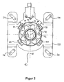
- FIG. 2 can be seen in the plan view of the open front of the safety gear 10, as already by centrifugal force as a blocking ball 50 executed blocking body 50 is driven outwardly against the inside of the housing molding 35 of the catching cage 30. This is due to the rotational acceleration which is above a limit value and is applied to the blocking means 40 designed as a star-shaped ratchet wheel 40 counterclockwise causes.
- the locking ball 50 is thus in the recess 42 at the outermost end of the trailing wall of the recess 42 and on the inside of the housing molding 35 of the catching cage 30 fitting.
- the blocking ball 50 is guided against the first catch cage stop 34 on the inside of the housing formation 35 of the catching cage 30.
- the first and second Fangharifiganschlag 34, 36 are formed in a common Gepurformung 35 of the catching cage 30, wherein the first Fangklafiganschlag 34 on the inside of the housing 35 and the second Fanghanfiganschlag 36 is located on the outside of the Gepuruseausformung 35.
- the second capture cage stop 36 may strike against the attachment carrier stopper 22.
- the outer surface of the catching cage 30 serves as a bearing surface for the pivot bearing 60, with which the partial relative rotational movement of the catching cage 30 against the mounting bracket 20 is made possible.
- the catch cage 30 can be rotated between the stops 22 and 26 of the mounting bracket.
- This rotation serves to prevent the locking effect caused by the abutment of the locking body 50 against the first catch cage impact 34 as in FIG FIG. 3 shown in a first step is achieved by allowing a damped further rotation of the catching cage 30 to stop the second Fangklafig stop 36 against the stop 22.
- dampers or damping means not shown are provided. These may also include braking means or be designed as a braking means.
- the safety gear 10 is aligned such that the stops 26 of the mounting bracket 20 and the stop 38 are adjacent to each other, so that for damping the locking movement an angle of about 45 ° by the housing 35 of the catching cage 30 is to sweep until the second Fangklafiganschlag Braked or attenuated abuts the stop 22 of the mounting bracket 20.
- the safety gear is axisymmetric with respect to the vertical axis H, which intersects the axis of rotation X of the winding shaft.
- the axis of rotation X extends perpendicular to the page in FIG. 2 and 3 , This results in the advantage that the safety gear can prevent an unwanted unwinding movement both in the direction of rotation against and in the clockwise direction.
- the safety gear 10 can be constructed and used identical for both sides or both ends of a winding shaft.
Landscapes
- Engineering & Computer Science (AREA)
- Structural Engineering (AREA)
- Architecture (AREA)
- Civil Engineering (AREA)
- Operating, Guiding And Securing Of Roll- Type Closing Members (AREA)
- Refuge Islands, Traffic Blockers, Or Guard Fence (AREA)
- Gears, Cams (AREA)
Applications Claiming Priority (1)
| Application Number | Priority Date | Filing Date | Title |
|---|---|---|---|
| DE200820015272 DE202008015272U1 (de) | 2008-11-18 | 2008-11-18 | Fangvorrichtung sowie Öffnungsabschluss mit Fangvorrichtung |
Publications (2)
| Publication Number | Publication Date |
|---|---|
| EP2186992A2 true EP2186992A2 (fr) | 2010-05-19 |
| EP2186992A3 EP2186992A3 (fr) | 2013-12-18 |
Family
ID=41796135
Family Applications (1)
| Application Number | Title | Priority Date | Filing Date |
|---|---|---|---|
| EP09010872.1A Withdrawn EP2186992A3 (fr) | 2008-11-18 | 2009-08-25 | Dispositif antichute et fermeture d'ouverture dotée d'un dispositif antichute |
Country Status (2)
| Country | Link |
|---|---|
| EP (1) | EP2186992A3 (fr) |
| DE (1) | DE202008015272U1 (fr) |
Families Citing this family (1)
| Publication number | Priority date | Publication date | Assignee | Title |
|---|---|---|---|---|
| ITPD20130198A1 (it) * | 2013-07-18 | 2015-01-19 | Alpac S R L Unipersonale | Struttura perfezionata di porta-avvolgibile e dispositivo per il montaggio facilitato di un albero di avvolgimento compreso in tale struttura perfezionata |
Citations (1)
| Publication number | Priority date | Publication date | Assignee | Title |
|---|---|---|---|---|
| DE3140792C2 (de) | 1981-10-14 | 1984-08-02 | Josef Timmer Gmbh, 4420 Coesfeld | Sicherungsvorrichtung gegen ungewolltes Abrollen von auf Wickelwellen aufgerollten Öffnungsabschlüssen |
Family Cites Families (3)
| Publication number | Priority date | Publication date | Assignee | Title |
|---|---|---|---|---|
| DE2902715C2 (de) * | 1979-01-25 | 1980-12-04 | Werner 4426 Vreden Haake | Sicherungsvorrichtung für auf eine Wickelwelle aufgerollte Öffnungsabschlüsse |
| DE3415878A1 (de) * | 1984-04-28 | 1985-10-31 | Werner 4286 Südlohn Haake | Sicherungsvorrichtung gegen ungewolltes abrollen von oeffnungsabschluessen |
| DE3435461C1 (de) * | 1984-09-27 | 1986-01-30 | André 4286 Südlohn Haake | Sicherungsvorrichtung gegen ungewolltes Abrollen von Rolltoren o.dgl. |
-
2008
- 2008-11-18 DE DE200820015272 patent/DE202008015272U1/de not_active Expired - Lifetime
-
2009
- 2009-08-25 EP EP09010872.1A patent/EP2186992A3/fr not_active Withdrawn
Patent Citations (1)
| Publication number | Priority date | Publication date | Assignee | Title |
|---|---|---|---|---|
| DE3140792C2 (de) | 1981-10-14 | 1984-08-02 | Josef Timmer Gmbh, 4420 Coesfeld | Sicherungsvorrichtung gegen ungewolltes Abrollen von auf Wickelwellen aufgerollten Öffnungsabschlüssen |
Also Published As
| Publication number | Publication date |
|---|---|
| EP2186992A3 (fr) | 2013-12-18 |
| DE202008015272U1 (de) | 2010-04-08 |
Similar Documents
| Publication | Publication Date | Title |
|---|---|---|
| EP3164283B1 (fr) | Ensemble d'entraînement et commande de volet | |
| EP3087237B1 (fr) | Dispositif de fermeture pour capot de véhicule et procédé | |
| DE102016119875B4 (de) | Rückprallunterdrückungssystem für eine Schiebetür | |
| EP2813653B1 (fr) | Agencement de poignée de porte pour un véhicule | |
| EP1842992B1 (fr) | Serrure de capot | |
| DE102013104144A1 (de) | Türaufbau mit einem die Türentriegelung verhindernden Sperrelement | |
| DE202005012659U1 (de) | Drehsperre | |
| EP3803006B1 (fr) | Ensemble poignée de porte conçu pour un véhicule automobile | |
| EP2186992A2 (fr) | Dispositif antichute et fermeture d'ouverture dotée d'un dispositif antichute | |
| AT515090B1 (de) | Sicherungsvorrichtung für Fenster oder Türen | |
| DE20022527U1 (de) | Antriebsvorrichtung für Beschattungseinrichtungen, insbesondere für Rollos | |
| WO2017059836A1 (fr) | Serrure de porte de véhicule automobile avec amortisseur de mouvement | |
| DE102021212303A1 (de) | Drehbegrenzungsbaugruppe und Lenkradbaugruppe für ein Steer-by-Wire-Lenksystem | |
| EP2031163A2 (fr) | Composant d'encliquetage pour une serrure de véhicule automobile dotée d'un point de palier à axe rotatif | |
| DE102014110755B3 (de) | Torantriebsvorrichtung mit Sperreinrichtung sowie damit versehenes Tor | |
| EP3093418A1 (fr) | Système d'aide à la fermeture | |
| EP3084105A1 (fr) | Serrure de porte de véhicule automobile | |
| DE2838354A1 (de) | Betaetigungseinrichtung fuer fahrzeugschloesser, insbesondere das motorhaubenschloss von kraftfahrzeugen | |
| DE20117440U1 (de) | Federwelle | |
| EP2450521A2 (fr) | Elément de support pour une porte roulante ou une grille roulante | |
| DE3233449A1 (de) | Sicherungsvorrichtung gegen ungewolltes abrollen von oeffnungsabschluessen | |
| DE102017110747B4 (de) | Federkassette für ein Dachrollosystem eines Kraftfahrzeugs und Baugruppe für ein Dachrollosystem eines Kraftfahrzeugs | |
| EP3216972B1 (fr) | Dispositif d'ombrage d'une ouverture de batiment et systeme de support associe | |
| AT503594B1 (de) | Laufwagen | |
| DE20306119U1 (de) | Höhensicherungsgerät |
Legal Events
| Date | Code | Title | Description |
|---|---|---|---|
| PUAI | Public reference made under article 153(3) epc to a published international application that has entered the european phase |
Free format text: ORIGINAL CODE: 0009012 |
|
| AK | Designated contracting states |
Kind code of ref document: A2 Designated state(s): AT BE BG CH CY CZ DE DK EE ES FI FR GB GR HR HU IE IS IT LI LT LU LV MC MK MT NL NO PL PT RO SE SI SK SM TR |
|
| AX | Request for extension of the european patent |
Extension state: AL BA RS |
|
| PUAL | Search report despatched |
Free format text: ORIGINAL CODE: 0009013 |
|
| AK | Designated contracting states |
Kind code of ref document: A3 Designated state(s): AT BE BG CH CY CZ DE DK EE ES FI FR GB GR HR HU IE IS IT LI LT LU LV MC MK MT NL NO PL PT RO SE SI SK SM TR |
|
| AX | Request for extension of the european patent |
Extension state: AL BA RS |
|
| RIC1 | Information provided on ipc code assigned before grant |
Ipc: E06B 9/174 20060101ALI20131112BHEP Ipc: E06B 9/84 20060101AFI20131112BHEP |
|
| 17P | Request for examination filed |
Effective date: 20140618 |
|
| 17Q | First examination report despatched |
Effective date: 20160902 |
|
| STAA | Information on the status of an ep patent application or granted ep patent |
Free format text: STATUS: THE APPLICATION IS DEEMED TO BE WITHDRAWN |
|
| 18D | Application deemed to be withdrawn |
Effective date: 20170314 |