EP2188092B1 - Appareil et procede de nettoyage de pieces metalliques - Google Patents
Appareil et procede de nettoyage de pieces metalliques Download PDFInfo
- Publication number
- EP2188092B1 EP2188092B1 EP08842509A EP08842509A EP2188092B1 EP 2188092 B1 EP2188092 B1 EP 2188092B1 EP 08842509 A EP08842509 A EP 08842509A EP 08842509 A EP08842509 A EP 08842509A EP 2188092 B1 EP2188092 B1 EP 2188092B1
- Authority
- EP
- European Patent Office
- Prior art keywords
- vessel
- electrochemical
- cleaning
- solution
- metal parts
- Prior art date
- Legal status (The legal status is an assumption and is not a legal conclusion. Google has not performed a legal analysis and makes no representation as to the accuracy of the status listed.)
- Not-in-force
Links
- 238000004140 cleaning Methods 0.000 title claims abstract description 30
- 229910052751 metal Inorganic materials 0.000 title claims abstract description 26
- 239000002184 metal Substances 0.000 title claims abstract description 26
- 238000000034 method Methods 0.000 title claims abstract description 11
- 239000000463 material Substances 0.000 claims abstract description 3
- 239000007787 solid Substances 0.000 claims abstract 2
- XEEYBQQBJWHFJM-UHFFFAOYSA-N Iron Chemical compound [Fe] XEEYBQQBJWHFJM-UHFFFAOYSA-N 0.000 claims description 4
- HCHKCACWOHOZIP-UHFFFAOYSA-N Zinc Chemical compound [Zn] HCHKCACWOHOZIP-UHFFFAOYSA-N 0.000 claims description 3
- XAGFODPZIPBFFR-UHFFFAOYSA-N aluminium Chemical compound [Al] XAGFODPZIPBFFR-UHFFFAOYSA-N 0.000 claims description 3
- 239000012530 fluid Substances 0.000 claims description 3
- 238000003756 stirring Methods 0.000 claims description 3
- 229910052725 zinc Inorganic materials 0.000 claims description 3
- 239000011701 zinc Substances 0.000 claims description 3
- FYYHWMGAXLPEAU-UHFFFAOYSA-N Magnesium Chemical compound [Mg] FYYHWMGAXLPEAU-UHFFFAOYSA-N 0.000 claims description 2
- ATJFFYVFTNAWJD-UHFFFAOYSA-N Tin Chemical compound [Sn] ATJFFYVFTNAWJD-UHFFFAOYSA-N 0.000 claims description 2
- 229910052782 aluminium Inorganic materials 0.000 claims description 2
- 229910052742 iron Inorganic materials 0.000 claims description 2
- 229910052749 magnesium Inorganic materials 0.000 claims description 2
- 239000011777 magnesium Substances 0.000 claims description 2
- 229910052718 tin Inorganic materials 0.000 claims description 2
- 239000000243 solution Substances 0.000 description 18
- XLYOFNOQVPJJNP-UHFFFAOYSA-N water Substances O XLYOFNOQVPJJNP-UHFFFAOYSA-N 0.000 description 10
- 238000010907 mechanical stirring Methods 0.000 description 5
- 238000005201 scrubbing Methods 0.000 description 5
- 238000006477 desulfuration reaction Methods 0.000 description 4
- 230000023556 desulfurization Effects 0.000 description 4
- BQCADISMDOOEFD-UHFFFAOYSA-N Silver Chemical group [Ag] BQCADISMDOOEFD-UHFFFAOYSA-N 0.000 description 3
- 239000000126 substance Substances 0.000 description 3
- 239000002699 waste material Substances 0.000 description 3
- CDBYLPFSWZWCQE-UHFFFAOYSA-L Sodium Carbonate Chemical compound [Na+].[Na+].[O-]C([O-])=O CDBYLPFSWZWCQE-UHFFFAOYSA-L 0.000 description 2
- PMZURENOXWZQFD-UHFFFAOYSA-L Sodium Sulfate Chemical compound [Na+].[Na+].[O-]S([O-])(=O)=O PMZURENOXWZQFD-UHFFFAOYSA-L 0.000 description 2
- 238000003487 electrochemical reaction Methods 0.000 description 2
- -1 hydride ions Chemical class 0.000 description 2
- 238000002347 injection Methods 0.000 description 2
- 239000007924 injection Substances 0.000 description 2
- 150000002500 ions Chemical class 0.000 description 2
- 239000007788 liquid Substances 0.000 description 2
- UMGDCJDMYOKAJW-UHFFFAOYSA-N thiourea Chemical compound NC(N)=S UMGDCJDMYOKAJW-UHFFFAOYSA-N 0.000 description 2
- BVKZGUZCCUSVTD-UHFFFAOYSA-L Carbonate Chemical compound [O-]C([O-])=O BVKZGUZCCUSVTD-UHFFFAOYSA-L 0.000 description 1
- KRKNYBCHXYNGOX-UHFFFAOYSA-K Citrate Chemical compound [O-]C(=O)CC(O)(CC([O-])=O)C([O-])=O KRKNYBCHXYNGOX-UHFFFAOYSA-K 0.000 description 1
- RWSOTUBLDIXVET-UHFFFAOYSA-N Dihydrogen sulfide Chemical compound S RWSOTUBLDIXVET-UHFFFAOYSA-N 0.000 description 1
- 229910000831 Steel Inorganic materials 0.000 description 1
- XSQUKJJJFZCRTK-UHFFFAOYSA-N Urea Natural products NC(N)=O XSQUKJJJFZCRTK-UHFFFAOYSA-N 0.000 description 1
- 230000004075 alteration Effects 0.000 description 1
- 239000011324 bead Substances 0.000 description 1
- 230000015572 biosynthetic process Effects 0.000 description 1
- 239000003153 chemical reaction reagent Substances 0.000 description 1
- 230000003009 desulfurizing effect Effects 0.000 description 1
- 239000003599 detergent Substances 0.000 description 1
- 239000003792 electrolyte Substances 0.000 description 1
- 238000005530 etching Methods 0.000 description 1
- 238000000605 extraction Methods 0.000 description 1
- 229910000037 hydrogen sulfide Inorganic materials 0.000 description 1
- 238000003754 machining Methods 0.000 description 1
- 239000002736 nonionic surfactant Substances 0.000 description 1
- 210000000056 organ Anatomy 0.000 description 1
- 230000000284 resting effect Effects 0.000 description 1
- 238000005096 rolling process Methods 0.000 description 1
- 238000006748 scratching Methods 0.000 description 1
- 230000002393 scratching effect Effects 0.000 description 1
- 229910052709 silver Inorganic materials 0.000 description 1
- 239000004332 silver Substances 0.000 description 1
- 229910000029 sodium carbonate Inorganic materials 0.000 description 1
- 229910052938 sodium sulfate Inorganic materials 0.000 description 1
- 235000011152 sodium sulphate Nutrition 0.000 description 1
- 239000010959 steel Substances 0.000 description 1
Images
Classifications
-
- B—PERFORMING OPERATIONS; TRANSPORTING
- B24—GRINDING; POLISHING
- B24B—MACHINES, DEVICES, OR PROCESSES FOR GRINDING OR POLISHING; DRESSING OR CONDITIONING OF ABRADING SURFACES; FEEDING OF GRINDING, POLISHING, OR LAPPING AGENTS
- B24B31/00—Machines or devices designed for polishing or abrading surfaces on work by means of tumbling apparatus or other apparatus in which the work and/or the abrasive material is loose; Accessories therefor
- B24B31/05—Machines or devices designed for polishing or abrading surfaces on work by means of tumbling apparatus or other apparatus in which the work and/or the abrasive material is loose; Accessories therefor involving a container formed as a conveyor belt
-
- B—PERFORMING OPERATIONS; TRANSPORTING
- B24—GRINDING; POLISHING
- B24B—MACHINES, DEVICES, OR PROCESSES FOR GRINDING OR POLISHING; DRESSING OR CONDITIONING OF ABRADING SURFACES; FEEDING OF GRINDING, POLISHING, OR LAPPING AGENTS
- B24B1/00—Processes of grinding or polishing; Use of auxiliary equipment in connection with such processes
- B24B1/002—Processes of grinding or polishing; Use of auxiliary equipment in connection with such processes using electric current
-
- C—CHEMISTRY; METALLURGY
- C25—ELECTROLYTIC OR ELECTROPHORETIC PROCESSES; APPARATUS THEREFOR
- C25F—PROCESSES FOR THE ELECTROLYTIC REMOVAL OF MATERIALS FROM OBJECTS; APPARATUS THEREFOR
- C25F1/00—Electrolytic cleaning, degreasing, pickling or descaling
Definitions
- the invention relates to an apparatus and a method for cleaning metal parts.
- the invention more particularly relates to an apparatus for desulfurizing, scrubbing and / or browning metal instruments such as cutlery, dishes, surgical instruments or, more generally, all kinds of metal instruments. It finds application particularly in hospitals, restaurants, hotels, slaughterhouses.
- Licences FR 2 682 630 and FR 2 881 069 describe a cleaning machine which comprises a tank in which is mounted a stirring member.
- the latter essentially comprises a moving band which is mounted on transverse rollers.
- the band moves under the action of a motor roller rotated by a drive member. It has a honeycomb structure allowing the passage of water and small waste.
- the strip forms a pocket for containing, on the one hand, a plurality of instruments to be treated, and on the other hand a load of cleaning utensils. It is bordered laterally by two vertical flat cheeks integral with the tank.
- the strip is partially immersed in a cleaning liquid, essentially water. This liquid passes freely through the intervals between the cheeks and the band on the one hand, through the cells of the band on the other hand.
- the machine has transverse deflectors arranged vis-à-vis the upper rollers on which the band bears. These baffles are used to block the utensils in their upward movement along the band in its direction of travel.
- utensils of a first type are loaded on the band.
- the machine then makes it possible to rub instruments using these utensils to take off the waste that adheres to it, this by avoiding scratching the instruments.
- utensils of a second type such as steel balls, are loaded on the strip, which allows for a browning operation, that is to say to harden the surface of the instruments to be treated using the beads.
- CH 353 596 which teaches a method of cleaning silverware and a machine for carrying out this method.
- This apparatus comprises a tank in which a basket is mounted. To perform an electrochemical treatment, the water in the tank is loaded with an aluminum powder.
- JP 05 214 600 discloses an apparatus and an electrolytic machining process.
- This apparatus comprises a vessel in which electrolytic treatment is carried out.
- the reagent is inseparable from the solution that fills the tank.
- the present invention thus relates to a single apparatus and a method for cleaning metal parts that allow desulfurization and cleaning and / or browning.
- a cleaning apparatus takes a tank in which is mounted a mechanical stirring member: the mechanical stirring member comprising a mobile band mounted on transverse rollers and whose upper section is free to deform under the weight the charge she bears; the cleaning apparatus further comprises an electrochemical object consisting of a reactive metal and arranged in the vessel, this vessel being made of a material distinct from this reactive metal; said electrochemical object is a container which has a shape and dimensions adapted to those of the tank and the mechanical stirring member to rest on this mechanical stirring member; in addition, this electrochemical object is massive and removable so that it can be removed from the tank.
- this electrochemical object is at least partially immersed in an electrochemical solution contained in the tank.
- this reactive metal belongs to the group comprising zinc, magnesium, aluminum, tin and iron.
- this container is pierced with openings for the passage of an electrochemical solution and the passage of air.
- the apparatus further comprises means for agitating a solution by injecting a fluid.
- this apparatus comprises air injection nozzles as well as an air transport duct up to these nozzles.
- the treatment time is adjusted to allow the etching of the immersed parts in the electrolyte, by ion transfer to the electrode.
- the apparatus comprises a cleaning machine MA and an object made of reactive metal EL.
- this object here takes the form of a removable basket PA which serves as a container. Without departing from the scope of the present invention, it could take a completely different form, a simple plate for example.
- the machine MA comprises a tank VE equipped with a lid PV.
- the tank is mounted on several feet and is provided with a drain hole (not shown).
- a drain hole not shown.
- the water supply, the electrical connectors, and the surveillance windows are not represented either.
- the machine contains a moving band BA resting on four transverse horizontal rollers, a motor roll RM, a follower roller RS, a first low roller RB1, and a second low roller RB2.
- the upper section BS of this band is free to deform under the weight of the load that it supports between the motor roller RM and the follower roller RS.
- the RM motor roller is higher than the follower roller.
- the upper section BS thus forms a pocket.
- the lower section BI of the band BA is in contact with the two bottom rollers RB1, RB2.
- the axes of the rollers RM, RS, RB1, RB2 are substantially horizontal and parallel, the motor roller RM being driven by a drive member such as an electric motor.
- the band BA then moves in the direction indicated by an arrow FL.
- the basket PA is introduced into the tank VE of the cleaning machine.
- the reactive metal object consists of a plurality of balls disposed on the upper section BS of the moving band. It is thus possible to carry out jointly a mechanical treatment and an electrochemical treatment.
- An electrochemical solution E is poured into the tank VE to cover the parts to be cleaned arranged in the basket PA.
- This solution E may consist essentially of water containing sodium carbonate, for example from 1% to 5% by weight of carbonate, and optionally of a nonionic surfactant - at a rate of 1 % to 3% by weight -, of citrate, and / or of sodium sulphate - in a proportion of 1% to 5% by weight -.
- This solution E can also be constituted by detergent dissolved in water or even by softened running water. Indeed, in one case as in the other, the salinity of the water is sufficient to allow the electrochemical reaction.
- the desulfurization is then carried out by transfer of free hydride ions generated on the surface of the basket PA. These ions migrate within the solution to the parts to be treated whose surface is covered with sulphide ions because of the difference in electropositivity between the silver and the reactive metal in which the basket is constituted. It follows a formation of gaseous hydrogen sulfide which emerges from the electrochemical solution.
- the electrochemical reaction can be accelerated by connecting the basket and the part (s) to be treated to a low voltage direct current source (a few volts).
- the basket PA may be a removable zinc container designed to receive several metal parts to be cleaned, whose shape and dimensions are adapted to those of the tank and the mechanical stirring member, to rest on - or in - this organ brewing mechanics.
- the machine further comprises BU stirring members for agitating the electrochemical solution by injecting a fluid therein, for example air injection nozzles.
- a fluid for example air injection nozzles.
- the air is conveyed via a CO transport pipe to the BU nozzles.
- a load of scrubbing utensils and a load of burnishing implements can then be introduced for this purpose into the tank VE.
- the utensils and the parts to be treated are then loaded in bulk on the moving band BA, and water is introduced into the tank, until partially immersing the two sections BS, BI of the band BA.
- the band BA is bordered by two vertical lateral cheeks parallel to the plane of the figure 2 .
- the scrubbing tools, burnishing tools and parts are brewed.
- a first phase of cleaning in this case a rubbing phase, the water level is lower than the level of the instruments.
- the rubbing utensils are pressed and jammed by the burnishing tools in contact with the pieces.
- Their protruding forms make it possible to perform an effective scrubbing action and consequently to promote an extraction of all the waste present in the cavities of the pieces.
Landscapes
- Engineering & Computer Science (AREA)
- Mechanical Engineering (AREA)
- Chemical & Material Sciences (AREA)
- Chemical Kinetics & Catalysis (AREA)
- Electrochemistry (AREA)
- Materials Engineering (AREA)
- Metallurgy (AREA)
- Organic Chemistry (AREA)
- Cleaning By Liquid Or Steam (AREA)
- Cleaning And De-Greasing Of Metallic Materials By Chemical Methods (AREA)
Description
- L'invention concerne un appareil et un procédé de nettoyage de pièces métalliques.
- L'invention concerne plus particulièrement un appareil qui permet de désulfurer, de frotter et/ou de brunir des instruments métalliques tels des couverts, des plats, des instruments chirurgicaux ou, plus généralement, toutes sortes d'instruments métalliques. Elle trouve application notamment dans les hôpitaux, les restaurants, les hôtels, les abattoirs.
- Les brevets
FR 2 682 630 FR 2 881 069 - De plus, la machine comporte des déflecteurs transversaux agencés en vis-à-vis des rouleaux supérieurs sur lesquels la bande prend appui. Ces déflecteurs permettent de bloquer les ustensiles dans leur mouvement ascensionnel le long de la bande dans son sens de défilement.
- Selon une première utilisation de cette machine, des ustensiles d'un premier type sont chargés sur la bande. La machine permet alors de frotter des instruments au moyen de ces ustensiles pour décoller les déchets qui y adhèrent, ceci en évitant de rayer les instruments.
- Selon une seconde utilisation de cette machine, des ustensiles d'un deuxième type tels que des billes en acier, sont chargés sur la bande, ce qui permet de réaliser une opération de brunissage, c'est-à-dire de durcir la surface des instruments à traiter à l'aide des billes.
- Une telle machine est mal adaptée au traitement de pièces métalliques ayant subi une altération chimique de leurs surfaces.
- Lorsque les pièces à nettoyer, en particulier des pièces en métal argenté, nécessitent de subir une désulfuration, ce traitement est généralement réalisé avant le nettoyage et/ou le brunissage dans un appareil distinct de la machine de nettoyage à bande mobile ou à tambour rotatif. La désulfuration était réalisée au moyen de thiourée, substance maintenant interdite par l'Union Européenne.
- On connaît également le document
CH 353 596 - On connaît encore le document
JP 05 214 600 - Dans un cas comme dans l'autre, le réactif est indissociable de la solution qui emplit la cuve. Il s'ensuit que si un traitement de nettoyage ou de brunissage doit précéder ou suivre le traitement chimique, il faut procéder à la vidange et peut-être même au nettoyage de la cuve.
- La présente invention a ainsi pour objet un unique appareil et un procédé de nettoyage de pièces métalliques qui permettent de réaliser une désulfuration et un nettoyage et/ou un brunissage.
- Selon l'invention, un appareil de nettoyage prend une cuve dans laquelle est monté un organe de brassage mécanique: l'organe de brassage mécanique comprenant une bande mobile montée sur des rouleaux transversaux et dont la section supérieure est libre de se déformer sous le poids de la charge qu'elle supporte ; l'appareil de nettoyage comporte en outre un objet électrochimique constitué dans un métal réactif et agencé dans la cuve, cette cuve étant réalisée dans un matériau distinct de ce métal réactif ; ledit objet électrochimique est un conteneur qui présente une forme et des dimensions adaptées à celles de la cuve et de l'organe de brassage mécanique pour reposer sur cette organe de brassage mécanique ; de plus, cet objet électrochimique est massif et amovible de sorte que l'on puisse l'extraire de la cuve.
- Eventuellement, cet objet électrochimique est au moins en partie immergé dans une solution électrochimique contenue dans la cuve.
- De préférence, ce métal réactif appartient à l'ensemble comprenant le zinc, le magnésium, l'aluminium, l'étain et le fer.
- Suivant le premier mode de réalisation, avantageusement, ce conteneur est percé d'ouvertures permettant le passage d'une solution électrochimique ainsi que le passage d'air.
- Suivant une caractéristique additionnelle, l'appareil comporte en outre des organes d'agitation d'une solution par injection d'un fluide.
- A titre d'exemple cet appareil comporte des buses d'injection d'air ainsi qu'un conduit de transport d'air jusqu'à ces buses.
- L'invention vise également un procédé de nettoyage de pièces métalliques mis en oeuvre avec un appareil selon l'une quelconque des revendications 1 à 6, procédé selon lequel :
- on introduit l'objet électrochimique dans la cuve,
- on verse dans la cuve une solution électrochimique,
- on introduit les pièces métalliques à nettoyer dans la cuve,
- après une durée déterminée, on vidange la solution électrochimique.
- La durée de traitement est ajustée pour permettre le décapage des pièces immergées dans l'électrolyte, par transfert d'ions vers l'électrode.
- La présente invention apparaîtra maintenant avec plus de détails dans le cadre de la description qui suit d'exemples de réalisation donnés à titre illustratif en se référant au dessin joint dans lequel :
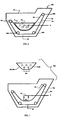
- la
figure 1 représente en coupe longitudinale un appareil de nettoyage selon l'invention qui comporte d'une part une machine de nettoyage à bande roulante et d'autre part un panier servant pour une désulfuration électrochimique, et - la
figure 2 représente en coupe longitudinale l'appareil de nettoyage de lafigure 1 dans lequel repose le panier. - Les éléments présents dans plusieurs figures sont affectés d'une seule et même référence.
- En référence aux
figures 1 et 2 , l'appareil comprend une machine de nettoyage MA et un objet en métal réactif EL. Suivant un premier mode de réalisation, cet objet prend ici la forme d'un panier amovible PA qui sert de conteneur. Sans sortir du cadre de la présente invention, il pourrait prendre une toute autre forme, une simple plaque par exemple. - La machine MA comprend une cuve VE munie d'un couvercle PV. La cuve est montée sur plusieurs pieds et est munie d'un orifice de vidange (non représentés). Afin de ne pas alourdir le dessin, l'arrivée d'eau, les connecteurs électriques, et les hublots de surveillance ne sont pas représentés non plus.
- La machine contient une bande mobile BA reposant sur quatre rouleaux horizontaux transversaux, un rouleau moteur RM, un rouleau suiveur RS, un premier rouleau bas RB1, et un deuxième rouleau bas RB2. La section supérieure BS de cette bande est libre de se déformer sous le poids de la charge qu'elle supporte entre le rouleau moteur RM et le rouleau suiveur RS.
- Le rouleau moteur RM est plus élevé que le rouleau suiveur. La section supérieure BS forme ainsi une poche. La section inférieure BI de la bande BA est en contact avec les deux rouleaux bas RB1, RB2. Les axes des rouleaux RM, RS, RB1, RB2 sont sensiblement horizontaux et parallèles, le rouleau moteur RM étant entraîné par un organe d'entraînement tel qu'un moteur électrique. La bande BA se déplace alors dans le sens indiqué par une flèche FL.
- Pour la désulfuration de pièces argentées, ces pièces sont chargées dans le panier PA dont les parois PAR sont percées d'orifices OR.
- Le panier PA est introduit dans la cuve VE de la machine de nettoyage. Alternativement, suivant un second mode de réalisation, l'objet en métal réactif consiste en une pluralité de billes disposées sur la section supérieure BS de la bande mobile. On a ainsi la possibilité de réaliser conjointement un traitement mécanique et un traitement électrochimique.
- Une solution électrochimique E est versée dans la cuve VE jusqu'à recouvrir les pièces à nettoyer disposées dans le panier PA.
- Cette solution E peut être essentiellement constituée par de l'eau additionnée de carbonate de sodium, par exemple à raison de 1% à 5% en masse de carbonate, et le cas échéant d'un tensio-actif non ionique - à raison de 1% à 3% en masse -, de citrate, et/ou de sulfate de sodium - à raison de 1% à 5% en masse -.
- Cette solution E peut également être constituée par de la lessive dissoute dans de l'eau ou bien même par de l'eau courante adoucie. En effet, dans un cas comme dans l'autre, la salinité de l'eau est suffisante pour permettre la réaction électrochimique.
- La désulfuration est alors réalisée par transfert d'ions hydrures libres générés à la surface du panier PA. Ces ions migrent au sein de la solution vers les pièces à traiter dont la surface est recouverte d'ions sulfure du fait de la différence d'électropositivité entre l'argent et le métal réactif dans lequel est constitué le panier. Il s'ensuit une formation de sulfure d'hydrogène gazeux qui se dégage de la solution électrochimique.
- La réaction électrochimique peut être accélérée en reliant le panier et la ou les pièces à traiter à une source de courant continu basse tension (quelques volts).
- Le panier PA peut être un conteneur amovible en zinc conçu pour recevoir plusieurs pièces métalliques à nettoyer, dont la forme et les dimensions sont adaptées à celles de la cuve et de l'organe mécanique de brassage, pour reposer sur - ou dans - cet organe mécanique de brassage.
- La machine comporte en outre des organes BU d'agitation pour agiter la solution électrochimique par injection d'un fluide en son sein, par exemple des buses d'injection d'air. L'air est acheminé par un conduit CO de transport jusqu'aux buses BU.
- Pour le nettoyage de pièces métalliques, on utilise un appareil selon l'invention, et :
- on introduit le panier PA dans la cuve VE,
- on verse la solution électrochimique E dans la cuve,
- on introduit les pièces métalliques à nettoyer dans le panier,
- on laisse reposer les pièces une certaine durée déterminée,
- finalement on vidange la solution électrochimique.
- Après rinçage des pièces, ces dernières peuvent être ré-introduites dans la machine de nettoyage pour frottage et/ou brunissage.
- Une charge d'ustensiles de frottage et une charge d'ustensiles de brunissage peuvent ensuite être introduites à cet effet dans la cuve VE.
- On pourrait même envisager de pratiquer simultanément la désulfuration et le brunissage.
- Les ustensiles ainsi que les pièces à traiter sont alors chargés en vrac sur la bande mobile BA, et de l'eau est introduite dans la cuve, jusqu'à immerger partiellement les deux sections BS, BI de la bande BA.
- La bande BA est bordée par deux joues latérales verticales parallèles au plan de la
figure 2 . - Lorsque le rouleau moteur RM entraîne la bande mobile BA, les ustensiles de frottage, les ustensiles de brunissage et les pièces se trouvent brassés. Dans une première phase de nettoyage, en l'occurrence une phase de frottage, le niveau de l'eau est plus bas que le niveau des instruments. Les ustensiles de frottage sont pressés et coincés par les ustensiles de brunissage au contact des pièces. Leurs formes saillantes permettent d'effectuer une action de frottage efficace et par conséquent de favoriser une extraction de tous les déchets présents dans les cavités des pièces.
- Les exemples de réalisation de l'invention présentés ci-dessus ont été choisis eu égard à leur caractère concret. Il ne serait cependant pas possible de répertorier de manière exhaustive tous les modes de réalisation que recouvre cette invention.
Claims (7)
- Appareil de nettoyage (MA) comprenant une cuve (VE) dans laquelle est monté un organe de brassage mécanique (BA), l'organe de brassage mécanique comprenant une bande (BA) mobile montée sur des rouleaux transversaux et dont la section supérieure (BS) est libre de se déformer sous le poids de la charge qu'elle supporte,
caractérisé en ce que : l'appareil de nettoyage comporte en outre un objet électrochimique (EL) constitué dans un métal réactif et agencé dans ladite cuve (VE), cette cuve étant réalisée dans un matériau distinct dudit métal réactif,- ledit objet électrochimique (EL) est un conteneur (PA) qui présente une forme et des dimensions adaptées à celles de la cuve et de l'organe de brassage mécanique, pour reposer sur cet organe de brassage mécanique, et- ledit objet électrochimique (EL) est massif et amovible de sorte que l'on puisse l'extraire de ladite cuve (VE). - Appareil selon la revendication 1, caractérisé en ce que ledit objet électrochimique (EL) est au moins en partie immergé dans une solution électrochimique (E) contenue dans ladite cuve (VE).
- Appareil selon l'une quelconque des revendications précédentes, caractérisé en ce que ledit métal réactif appartient à l'ensemble comprenant le zinc, le magnésium, l'aluminium, l'étain et le fer.
- Appareil selon la revendication 1, caractérisé en ce que ledit conteneur (PA) est percé d'ouvertures (OR) permettant le passage d'une solution électrochimique ainsi que le passage d'air.
- Appareil selon l'une quelconque des revendications précédentes, caractérisé en ce qu'il comporte en outre des organes (BU) d'agitation d'une solution par injection d'un fluide.
- Appareil selon la revendication 5, caractérisé en ce qu'il comporte des buses (BU) d'injection d'air ainsi qu'un conduit (CO) de transport d'air jusqu'à ces buses.
- Procédé de nettoyage de pièces métalliques caractérisé en ce que, mis en oeuvre avec un appareil selon l'une quelconque des revendications 1 à 6,- on introduit ledit objet électrochimique (EL) dans ladite cuve (VE),- on verse dans ladite cuve (VE) une solution électrochimique (E),- on introduit les pièces métalliques à nettoyer dans ladite cuve (VE),- après une durée déterminée, on vidange la solution électrochimique (E).
Applications Claiming Priority (2)
| Application Number | Priority Date | Filing Date | Title |
|---|---|---|---|
| FR0705687 | 2007-08-03 | ||
| PCT/FR2008/001154 WO2009053547A2 (fr) | 2007-08-03 | 2008-08-01 | Appareil et procede de nettoyage de pieces metalliques |
Publications (2)
| Publication Number | Publication Date |
|---|---|
| EP2188092A2 EP2188092A2 (fr) | 2010-05-26 |
| EP2188092B1 true EP2188092B1 (fr) | 2011-07-06 |
Family
ID=39166694
Family Applications (1)
| Application Number | Title | Priority Date | Filing Date |
|---|---|---|---|
| EP08842509A Not-in-force EP2188092B1 (fr) | 2007-08-03 | 2008-08-01 | Appareil et procede de nettoyage de pieces metalliques |
Country Status (3)
| Country | Link |
|---|---|
| EP (1) | EP2188092B1 (fr) |
| AT (1) | ATE515370T1 (fr) |
| WO (1) | WO2009053547A2 (fr) |
Family Cites Families (2)
| Publication number | Priority date | Publication date | Assignee | Title |
|---|---|---|---|---|
| CH306012A (fr) * | 1952-06-06 | 1955-03-31 | Gay Balmaz Maurice | Matériel servant à décaper l'argenterie. |
| CH353596A (fr) * | 1959-10-02 | 1961-04-15 | Gay Balmaz Maurice | Procédé de nettoyage de pièces d'argenterie et machine pour la mise en oeuvre de ce procédé |
-
2008
- 2008-08-01 WO PCT/FR2008/001154 patent/WO2009053547A2/fr not_active Ceased
- 2008-08-01 EP EP08842509A patent/EP2188092B1/fr not_active Not-in-force
- 2008-08-01 AT AT08842509T patent/ATE515370T1/de not_active IP Right Cessation
Also Published As
| Publication number | Publication date |
|---|---|
| ATE515370T1 (de) | 2011-07-15 |
| WO2009053547A3 (fr) | 2009-08-20 |
| WO2009053547A2 (fr) | 2009-04-30 |
| EP2188092A2 (fr) | 2010-05-26 |
Similar Documents
| Publication | Publication Date | Title |
|---|---|---|
| EP2000564A1 (fr) | Systèmes et procédés de traitement de surface de pièce de travail | |
| EP2188092B1 (fr) | Appareil et procede de nettoyage de pieces metalliques | |
| FR2906265A1 (fr) | Installation de traitement de surface de pieces par immerssion dans un liquide de traitement. | |
| KR20110070867A (ko) | 웨이퍼들을 웨이퍼 지지부로부터 분리하는 방법 및 그를 위한 장치 | |
| FR2639962A1 (fr) | Procede et appareil pour eliminer electrolytiquement des couches protectrices d'un substrat metallique en feuille applicables notamment aux circuits imprimes | |
| KR20200062044A (ko) | 보유 지지 지그 | |
| KR20080021362A (ko) | 파이프 내면의 전해연마 장치 및 방법 | |
| FR2659090A1 (fr) | Dispositif et procede pour la recuperation et le recyclage de solutions de traitement de surface adherentes dans des futs et leurs charges. | |
| JP2911406B2 (ja) | 表面処理装置 | |
| EP2170555B1 (fr) | Machine de nettoyage | |
| WO2025104337A1 (fr) | Poste de chargement et installation comprenant un tel poste de chargement | |
| CN105648506A (zh) | 镀敷装置、镀敷单元以及镀敷流水线 | |
| JP5984920B2 (ja) | 非シアン化物ベースの電解研磨 | |
| US5824119A (en) | Process for immersing a substrate in a plurality of processing baths | |
| JPH09257994A (ja) | 放射性廃棄物の放射能除染装置 | |
| CN223669810U (zh) | 清洗设备 | |
| CN207507900U (zh) | 金属碎块清洗装置 | |
| CN220514889U (zh) | 一种用于废钢回收的清洗装置 | |
| EP0149938A2 (fr) | Procédé électrochimique pour enlever la gangue entourant des éléments métalliques dans des matériaux en vrac | |
| WO1999019541A1 (fr) | Recipient pour la desoxydation de l'argenterie et moyens associes | |
| JP2008300084A (ja) | 扁平形アルカリ電池の電極缶メッキ方法、扁平形アルカリ電池の負極缶メッキ方法、扁平形アルカリ電池の負極缶メッキ収装置、扁平形アルカリ電池の負極缶エッチング装置、扁平形アルカリ電池の負極缶表面改質装置、扁平形アルカリ電池の負極缶洗浄装置及び扁平形アルカリ電池の負極缶乾燥装置 | |
| KR200269655Y1 (ko) | 시편세척장치 | |
| JP3594621B2 (ja) | 電気絶縁したコンベヤーを用いて亜鉛メッキ鋼を脱亜鉛化する方法 | |
| JP5650986B2 (ja) | 無排水による表面処理装置 | |
| JP3189949B2 (ja) | 電解母板研磨装置及びそれを組み込んだ種板自動剥取システム |
Legal Events
| Date | Code | Title | Description |
|---|---|---|---|
| PUAI | Public reference made under article 153(3) epc to a published international application that has entered the european phase |
Free format text: ORIGINAL CODE: 0009012 |
|
| 17P | Request for examination filed |
Effective date: 20100302 |
|
| AK | Designated contracting states |
Kind code of ref document: A2 Designated state(s): AT BE BG CH CY CZ DE DK EE ES FI FR GB GR HR HU IE IS IT LI LT LU LV MC MT NL NO PL PT RO SE SI SK TR |
|
| AX | Request for extension of the european patent |
Extension state: AL BA MK RS |
|
| GRAP | Despatch of communication of intention to grant a patent |
Free format text: ORIGINAL CODE: EPIDOSNIGR1 |
|
| GRAC | Information related to communication of intention to grant a patent modified |
Free format text: ORIGINAL CODE: EPIDOSCIGR1 |
|
| GRAC | Information related to communication of intention to grant a patent modified |
Free format text: ORIGINAL CODE: EPIDOSCIGR1 |
|
| DAX | Request for extension of the european patent (deleted) | ||
| GRAS | Grant fee paid |
Free format text: ORIGINAL CODE: EPIDOSNIGR3 |
|
| GRAA | (expected) grant |
Free format text: ORIGINAL CODE: 0009210 |
|
| AK | Designated contracting states |
Kind code of ref document: B1 Designated state(s): AT BE BG CH CY CZ DE DK EE ES FI FR GB GR HR HU IE IS IT LI LT LU LV MC MT NL NO PL PT RO SE SI SK TR |
|
| REG | Reference to a national code |
Ref country code: GB Ref legal event code: FG4D Free format text: NOT ENGLISH |
|
| REG | Reference to a national code |
Ref country code: CH Ref legal event code: EP |
|
| REG | Reference to a national code |
Ref country code: IE Ref legal event code: FG4D Free format text: LANGUAGE OF EP DOCUMENT: FRENCH |
|
| REG | Reference to a national code |
Ref country code: DE Ref legal event code: R096 Ref document number: 602008008147 Country of ref document: DE Effective date: 20110901 |
|
| REG | Reference to a national code |
Ref country code: NL Ref legal event code: VDEP Effective date: 20110706 |
|
| PG25 | Lapsed in a contracting state [announced via postgrant information from national office to epo] |
Ref country code: SI Free format text: LAPSE BECAUSE OF FAILURE TO SUBMIT A TRANSLATION OF THE DESCRIPTION OR TO PAY THE FEE WITHIN THE PRESCRIBED TIME-LIMIT Effective date: 20110706 |
|
| PG25 | Lapsed in a contracting state [announced via postgrant information from national office to epo] |
Ref country code: MT Free format text: LAPSE BECAUSE OF FAILURE TO SUBMIT A TRANSLATION OF THE DESCRIPTION OR TO PAY THE FEE WITHIN THE PRESCRIBED TIME-LIMIT Effective date: 20110706 |
|
| REG | Reference to a national code |
Ref country code: AT Ref legal event code: MK05 Ref document number: 515370 Country of ref document: AT Kind code of ref document: T Effective date: 20110706 |
|
| PG25 | Lapsed in a contracting state [announced via postgrant information from national office to epo] |
Ref country code: NO Free format text: LAPSE BECAUSE OF FAILURE TO SUBMIT A TRANSLATION OF THE DESCRIPTION OR TO PAY THE FEE WITHIN THE PRESCRIBED TIME-LIMIT Effective date: 20111006 Ref country code: FI Free format text: LAPSE BECAUSE OF FAILURE TO SUBMIT A TRANSLATION OF THE DESCRIPTION OR TO PAY THE FEE WITHIN THE PRESCRIBED TIME-LIMIT Effective date: 20110706 Ref country code: PT Free format text: LAPSE BECAUSE OF FAILURE TO SUBMIT A TRANSLATION OF THE DESCRIPTION OR TO PAY THE FEE WITHIN THE PRESCRIBED TIME-LIMIT Effective date: 20111107 Ref country code: IS Free format text: LAPSE BECAUSE OF FAILURE TO SUBMIT A TRANSLATION OF THE DESCRIPTION OR TO PAY THE FEE WITHIN THE PRESCRIBED TIME-LIMIT Effective date: 20111106 Ref country code: NL Free format text: LAPSE BECAUSE OF FAILURE TO SUBMIT A TRANSLATION OF THE DESCRIPTION OR TO PAY THE FEE WITHIN THE PRESCRIBED TIME-LIMIT Effective date: 20110706 Ref country code: LT Free format text: LAPSE BECAUSE OF FAILURE TO SUBMIT A TRANSLATION OF THE DESCRIPTION OR TO PAY THE FEE WITHIN THE PRESCRIBED TIME-LIMIT Effective date: 20110706 Ref country code: SE Free format text: LAPSE BECAUSE OF FAILURE TO SUBMIT A TRANSLATION OF THE DESCRIPTION OR TO PAY THE FEE WITHIN THE PRESCRIBED TIME-LIMIT Effective date: 20110706 Ref country code: HR Free format text: LAPSE BECAUSE OF FAILURE TO SUBMIT A TRANSLATION OF THE DESCRIPTION OR TO PAY THE FEE WITHIN THE PRESCRIBED TIME-LIMIT Effective date: 20110706 |
|
| REG | Reference to a national code |
Ref country code: IE Ref legal event code: FD4D |
|
| BERE | Be: lapsed |
Owner name: LAUJON, MARIE ROSE Effective date: 20110831 Owner name: LAUJON, GUILLAUME Effective date: 20110831 |
|
| PG25 | Lapsed in a contracting state [announced via postgrant information from national office to epo] |
Ref country code: LV Free format text: LAPSE BECAUSE OF FAILURE TO SUBMIT A TRANSLATION OF THE DESCRIPTION OR TO PAY THE FEE WITHIN THE PRESCRIBED TIME-LIMIT Effective date: 20110706 Ref country code: AT Free format text: LAPSE BECAUSE OF FAILURE TO SUBMIT A TRANSLATION OF THE DESCRIPTION OR TO PAY THE FEE WITHIN THE PRESCRIBED TIME-LIMIT Effective date: 20110706 Ref country code: GR Free format text: LAPSE BECAUSE OF FAILURE TO SUBMIT A TRANSLATION OF THE DESCRIPTION OR TO PAY THE FEE WITHIN THE PRESCRIBED TIME-LIMIT Effective date: 20111007 Ref country code: CY Free format text: LAPSE BECAUSE OF FAILURE TO SUBMIT A TRANSLATION OF THE DESCRIPTION OR TO PAY THE FEE WITHIN THE PRESCRIBED TIME-LIMIT Effective date: 20110706 Ref country code: PL Free format text: LAPSE BECAUSE OF FAILURE TO SUBMIT A TRANSLATION OF THE DESCRIPTION OR TO PAY THE FEE WITHIN THE PRESCRIBED TIME-LIMIT Effective date: 20110706 |
|
| PG25 | Lapsed in a contracting state [announced via postgrant information from national office to epo] |
Ref country code: MC Free format text: LAPSE BECAUSE OF NON-PAYMENT OF DUE FEES Effective date: 20110831 |
|
| PG25 | Lapsed in a contracting state [announced via postgrant information from national office to epo] |
Ref country code: CZ Free format text: LAPSE BECAUSE OF FAILURE TO SUBMIT A TRANSLATION OF THE DESCRIPTION OR TO PAY THE FEE WITHIN THE PRESCRIBED TIME-LIMIT Effective date: 20110706 Ref country code: SK Free format text: LAPSE BECAUSE OF FAILURE TO SUBMIT A TRANSLATION OF THE DESCRIPTION OR TO PAY THE FEE WITHIN THE PRESCRIBED TIME-LIMIT Effective date: 20110706 Ref country code: IE Free format text: LAPSE BECAUSE OF FAILURE TO SUBMIT A TRANSLATION OF THE DESCRIPTION OR TO PAY THE FEE WITHIN THE PRESCRIBED TIME-LIMIT Effective date: 20110706 |
|
| PLBE | No opposition filed within time limit |
Free format text: ORIGINAL CODE: 0009261 |
|
| STAA | Information on the status of an ep patent application or granted ep patent |
Free format text: STATUS: NO OPPOSITION FILED WITHIN TIME LIMIT |
|
| PG25 | Lapsed in a contracting state [announced via postgrant information from national office to epo] |
Ref country code: BE Free format text: LAPSE BECAUSE OF NON-PAYMENT OF DUE FEES Effective date: 20110831 Ref country code: IT Free format text: LAPSE BECAUSE OF FAILURE TO SUBMIT A TRANSLATION OF THE DESCRIPTION OR TO PAY THE FEE WITHIN THE PRESCRIBED TIME-LIMIT Effective date: 20110706 Ref country code: EE Free format text: LAPSE BECAUSE OF FAILURE TO SUBMIT A TRANSLATION OF THE DESCRIPTION OR TO PAY THE FEE WITHIN THE PRESCRIBED TIME-LIMIT Effective date: 20110706 Ref country code: RO Free format text: LAPSE BECAUSE OF FAILURE TO SUBMIT A TRANSLATION OF THE DESCRIPTION OR TO PAY THE FEE WITHIN THE PRESCRIBED TIME-LIMIT Effective date: 20110706 |
|
| REG | Reference to a national code |
Ref country code: DE Ref legal event code: R119 Ref document number: 602008008147 Country of ref document: DE Effective date: 20120301 |
|
| 26N | No opposition filed |
Effective date: 20120411 |
|
| PG25 | Lapsed in a contracting state [announced via postgrant information from national office to epo] |
Ref country code: DK Free format text: LAPSE BECAUSE OF FAILURE TO SUBMIT A TRANSLATION OF THE DESCRIPTION OR TO PAY THE FEE WITHIN THE PRESCRIBED TIME-LIMIT Effective date: 20110706 |
|
| REG | Reference to a national code |
Ref country code: CH Ref legal event code: PL |
|
| GBPC | Gb: european patent ceased through non-payment of renewal fee |
Effective date: 20120801 |
|
| PG25 | Lapsed in a contracting state [announced via postgrant information from national office to epo] |
Ref country code: ES Free format text: LAPSE BECAUSE OF FAILURE TO SUBMIT A TRANSLATION OF THE DESCRIPTION OR TO PAY THE FEE WITHIN THE PRESCRIBED TIME-LIMIT Effective date: 20111017 Ref country code: CH Free format text: LAPSE BECAUSE OF NON-PAYMENT OF DUE FEES Effective date: 20120831 Ref country code: LI Free format text: LAPSE BECAUSE OF NON-PAYMENT OF DUE FEES Effective date: 20120831 |
|
| PG25 | Lapsed in a contracting state [announced via postgrant information from national office to epo] |
Ref country code: LU Free format text: LAPSE BECAUSE OF NON-PAYMENT OF DUE FEES Effective date: 20110801 |
|
| PG25 | Lapsed in a contracting state [announced via postgrant information from national office to epo] |
Ref country code: BG Free format text: LAPSE BECAUSE OF FAILURE TO SUBMIT A TRANSLATION OF THE DESCRIPTION OR TO PAY THE FEE WITHIN THE PRESCRIBED TIME-LIMIT Effective date: 20111006 Ref country code: DE Free format text: LAPSE BECAUSE OF NON-PAYMENT OF DUE FEES Effective date: 20120301 |
|
| PG25 | Lapsed in a contracting state [announced via postgrant information from national office to epo] |
Ref country code: GB Free format text: LAPSE BECAUSE OF NON-PAYMENT OF DUE FEES Effective date: 20120801 |
|
| PG25 | Lapsed in a contracting state [announced via postgrant information from national office to epo] |
Ref country code: TR Free format text: LAPSE BECAUSE OF FAILURE TO SUBMIT A TRANSLATION OF THE DESCRIPTION OR TO PAY THE FEE WITHIN THE PRESCRIBED TIME-LIMIT Effective date: 20110706 |
|
| PG25 | Lapsed in a contracting state [announced via postgrant information from national office to epo] |
Ref country code: HU Free format text: LAPSE BECAUSE OF FAILURE TO SUBMIT A TRANSLATION OF THE DESCRIPTION OR TO PAY THE FEE WITHIN THE PRESCRIBED TIME-LIMIT Effective date: 20110706 |
|
| PGFP | Annual fee paid to national office [announced via postgrant information from national office to epo] |
Ref country code: FR Payment date: 20140808 Year of fee payment: 7 |
|
| REG | Reference to a national code |
Ref country code: FR Ref legal event code: ST Effective date: 20160429 |
|
| PG25 | Lapsed in a contracting state [announced via postgrant information from national office to epo] |
Ref country code: FR Free format text: LAPSE BECAUSE OF NON-PAYMENT OF DUE FEES Effective date: 20150831 |