EP2188546B1 - Dispositif de commande de couple de rotation à actionnement électromagnétique - Google Patents
Dispositif de commande de couple de rotation à actionnement électromagnétique Download PDFInfo
- Publication number
- EP2188546B1 EP2188546B1 EP08785250A EP08785250A EP2188546B1 EP 2188546 B1 EP2188546 B1 EP 2188546B1 EP 08785250 A EP08785250 A EP 08785250A EP 08785250 A EP08785250 A EP 08785250A EP 2188546 B1 EP2188546 B1 EP 2188546B1
- Authority
- EP
- European Patent Office
- Prior art keywords
- control device
- torque control
- disc
- electromagnets
- electromagnetically actuatable
- Prior art date
- Legal status (The legal status is an assumption and is not a legal conclusion. Google has not performed a legal analysis and makes no representation as to the accuracy of the status listed.)
- Active
Links
Images
Classifications
-
- F—MECHANICAL ENGINEERING; LIGHTING; HEATING; WEAPONS; BLASTING
- F16—ENGINEERING ELEMENTS AND UNITS; GENERAL MEASURES FOR PRODUCING AND MAINTAINING EFFECTIVE FUNCTIONING OF MACHINES OR INSTALLATIONS; THERMAL INSULATION IN GENERAL
- F16D—COUPLINGS FOR TRANSMITTING ROTATION; CLUTCHES; BRAKES
- F16D27/00—Magnetically- or electrically- actuated clutches; Control or electric circuits therefor
- F16D27/004—Magnetically- or electrically- actuated clutches; Control or electric circuits therefor with permanent magnets combined with electromagnets
-
- F—MECHANICAL ENGINEERING; LIGHTING; HEATING; WEAPONS; BLASTING
- F16—ENGINEERING ELEMENTS AND UNITS; GENERAL MEASURES FOR PRODUCING AND MAINTAINING EFFECTIVE FUNCTIONING OF MACHINES OR INSTALLATIONS; THERMAL INSULATION IN GENERAL
- F16D—COUPLINGS FOR TRANSMITTING ROTATION; CLUTCHES; BRAKES
- F16D2121/00—Type of actuator operation force
- F16D2121/18—Electric or magnetic
- F16D2121/20—Electric or magnetic using electromagnets
-
- F—MECHANICAL ENGINEERING; LIGHTING; HEATING; WEAPONS; BLASTING
- F16—ENGINEERING ELEMENTS AND UNITS; GENERAL MEASURES FOR PRODUCING AND MAINTAINING EFFECTIVE FUNCTIONING OF MACHINES OR INSTALLATIONS; THERMAL INSULATION IN GENERAL
- F16D—COUPLINGS FOR TRANSMITTING ROTATION; CLUTCHES; BRAKES
- F16D2125/00—Components of actuators
- F16D2125/18—Mechanical mechanisms
- F16D2125/20—Mechanical mechanisms converting rotation to linear movement or vice versa
- F16D2125/34—Mechanical mechanisms converting rotation to linear movement or vice versa acting in the direction of the axis of rotation
- F16D2125/36—Helical cams, Ball-rotating ramps
-
- F—MECHANICAL ENGINEERING; LIGHTING; HEATING; WEAPONS; BLASTING
- F16—ENGINEERING ELEMENTS AND UNITS; GENERAL MEASURES FOR PRODUCING AND MAINTAINING EFFECTIVE FUNCTIONING OF MACHINES OR INSTALLATIONS; THERMAL INSULATION IN GENERAL
- F16D—COUPLINGS FOR TRANSMITTING ROTATION; CLUTCHES; BRAKES
- F16D2129/00—Type of operation source for auxiliary mechanisms
- F16D2129/06—Electric or magnetic
- F16D2129/065—Permanent magnets
-
- H—ELECTRICITY
- H02—GENERATION; CONVERSION OR DISTRIBUTION OF ELECTRIC POWER
- H02K—DYNAMO-ELECTRIC MACHINES
- H02K2213/00—Specific aspects, not otherwise provided for and not covered by codes H02K2201/00 - H02K2211/00
- H02K2213/09—Machines characterised by the presence of elements which are subject to variation, e.g. adjustable bearings, reconfigurable windings, variable pitch ventilators
Definitions
- the invention relates to an electromagnetically operable torque control device.
- the invention is therefore based on the object to reduce the energy consumption in industrial plants.
- the object is achieved in the torque control device according to the features indicated in claim 1.
- the torque control device is electromagnetically operable, in particular as a brake or clutch can be realized, and that radially oriented electromagnets are provided, which are radially oriented on an axially opposite disc arranged permanent magnets, wherein a means for implementing a rotational movement of the disc in an axial movement of a pressure plate is provided, wherein from the pressure plate a rotatable with a shaft, slidably disposed in the axial direction friction disc can be pressed onto a brake bearing plate, in particular depending on the axial position of the pressure plate, wherein a spring element is provided in such a way that counteracts the effect of the magnetic force of the electromagnets rotational movement.
- the advantage here is that the torque control device is designed very compact, has low energy consumption, since permanent magnets are used and the clutch or braking torque, so the through or derived torque is controllable.
- the additional permanent magnets are all carried out the same way.
- Vorzugswiese is also the strength of the electromagnets with their maximum allowable Bestromungswert designed such that the amount of achievable magnetic field strength substantially equal to the amount of magnetic field strength of the permanent magnet.
- the electromagnets are arranged in an axial plane.
- the advantage here is that they can be mounted on a mounting plate and thus the production and wiring is possible easily and with little effort.
- the spring element is arranged oriented in the circumferential direction, in particular designed as a spiral spring.
- the friction disc on an internal toothing, in particular straight toothing, which is in engagement with a driving toothing of the shaft is in engagement with a driving toothing of the shaft.
- the friction disc is provided on both sides with brake pads.
- the advantage here is that a friction force can be generated on both sides.
- the brake bearing plate is designed as a brake disc, in particular its axial position is provided adjustable.
- the advantage here is that the assembly is easy and instead of a fixed housing part an axially adjustable part is used.
- the means has two interacting via an inclined plane parts.
- the means comprises a linear ball screw, a threaded part or a screw, in particular with at least one partial or full thread.
- the electromagnets are designed and energized such that the radial component of the magnetic field of the electromagnets is oriented opposite to the magnetization of the permanent magnets.
- the advantage here is that when energizing the electromagnet, the permanent magnets are rotated very quickly and with great force in the circumferential direction until they each reach an angular position, which is located between two mutually adjacent electromagnet.
- the disc is rotatable relative to the arrangement of the electromagnet.
- the advantage here is that the electromagnets are firmly connected to the housing and from the disk by means of rotary motion, the effect of the magnetic forces can be forwarded to the means for implementation in axial movement.
- a controller is provided, in particular, this is designed integrated.
- electronic power semiconductors are provided for controlling the current of the windings of the electromagnets.
- the advantage here is that an electrically adjustable, controllable braking torque is providable. For couplings, the transmittable torque is adjusted accordingly.
- clamping rings for adjusting the axial mobility of the disc are provided.
- the advantage here is that the axial movement is mechanically limited, in particular by striking.
- additional permanent magnets are connected directly or indirectly to the electromagnets, in particular for the realization of a quiescent current brake.
- the advantage here is that a quiescent current brake can be realized.
- the additional, in addition to the electromagnets arranged permanent magnet when energizing the electromagnets are substantially compensated and provided on the disc permanent magnets remain without effect
- the permanent magnets of the disc with the additional, arranged next to the electromagnet permanent magnets in operative connection in turn the magnetization direction of the two types of permanent magnets is oriented in the opposite direction in the radial direction.
- a rotational movement of the disc is effected, which has the goal that the additional permanent magnets each reach an angular position between two permanent magnets of the disc.
- the permanent magnets of the disc are all made the same.
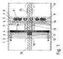
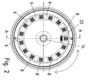
- FIG. 1 is a cross section through the brake containing the shaft axis and in FIG. 2 a cross section whose normal has the shaft axis shown.
- the shaft 14 is mounted on bearings 15 relative to the housing 17.
- a slide 16 is mounted, are mounted on the electromagnets. These are oriented such that the magnetization direction is aligned in their coil cores 8 substantially in the radial direction. In FIG. 2 this is shown in more detail.
- friction friction friction plate 4 has towards the shaft on an internal toothing, with which it is engaged with the driving toothing 10 of the shaft 14.
- the friction plate 4 is positively connected to the shaft 14, but arranged axially displaceable.
- a thrust washer 12 is disposed on the axially other side of the friction washer 4. This thrust washer 12 is also arranged axially displaceable, wherein it has an external toothing, which is in engagement with the internal toothing of a ring gear 11.
- the thrust washer 12 is connected to an upper inclined part 13 having a part with the disc 16, are arranged on the radially oriented permanent magnets 6.
- the number and the mutual angular distance of the permanent magnets 6 and the electromagnets is the same.
- the permanent magnets When current is applied to the electromagnets 9, the permanent magnets are oriented in accordance with the magnetic field in such a way that a radial position is aimed between the magnets when the magnetic field direction of the electromagnets 9 is reversed in the radial direction as the magnetization direction of the permanent magnets 6.
- the permanent magnets 6 cause a rotational movement of the disc 16.
- this rotational movement is translated into an axial displacement of the pressure plate 12, which thus presses the rotatable friction disc on the brake disc.
- the return spring 20 oriented in the circumferential direction causes a return of the disc 16 and thus a release of the brake.
- the return spring 20 is effective between the disc 16 and housing 17 or a correspondingly connected part.
- the spring force of the return spring 20 overcomes the forces caused by the magnetic fields and operates in a similar manner, as described.
- the inclined plane 13 has a normal direction, which is provided obliquely to the axial direction.
- the angle between the normal direction and the axial direction has a value between 0 ° and 90 °, in particular between 20 ° and 60 °.
- the braking force is controllable.
- an operating current brake is realized:
- the energization of the electromagnets is carried out as described above, that the magnetic field of the permanent magnets counteracts the magnetic fields of the electromagnets.
- a quiescent current brake is realized.
- 7 instead of only the electromagnets, as in figure 1 and 2 Also shown mounted permanent magnets whose field is essentially neutralized by the electromagnet.
- the permanent magnets of the disc 16 and those of the mounting plate 7 cooperate and cause a rotational movement, which in turn causes the brake to engage. Only when energized, the brake is released by means of the force caused by the return spring.
- the same principle as in the described brake is designed for an electromagnetically actuated clutch.
- the housing is a rotatably mounted shaft part.
Landscapes
- Engineering & Computer Science (AREA)
- General Engineering & Computer Science (AREA)
- Physics & Mathematics (AREA)
- Electromagnetism (AREA)
- Mechanical Engineering (AREA)
- Braking Arrangements (AREA)
Claims (13)
- Dispositif de commande de couple à actionnement électromagnétique, en particulier frein ou embrayage, dans lequel sont prévus des électroaimants orientés radialement en face desquels sont disposés des aimants permanents (6) orientés radialement sur un disque (16) opposé axialement,
caractérisé en ce que
un moyen (13) pour convertir un mouvement de rotation du disque (16) en un mouvement axial d'un disque de pression (12) est prévu,
le disque de pression (12) peut presser un disque de friction (14) mobile en rotation avec un arbre (14), disposé de manière à pouvoir coulisser en direction axiale, contre un flasque de frein (3), en particulier en fonction de la position axiale du disque de pression (12),
un élément à ressort (20) étant prévu, qui agit en sens inverse du mouvement de rotation pouvant être généré par la force magnétique des électroaimants (9). - Dispositif de commande de couple à actionnement électromagnétique selon au moins une des revendications précédentes,
caractérisé en ce que
les électroaimants (9) sont disposés dans un plan axial. - Dispositif de commande de couple à actionnement électromagnétique selon au moins une des revendications précédentes,
caractérisé en ce que
l'élément à ressort est orienté en direction circonférentielle, en particulier réalisé sous la forme d'un ressort spiral. - Dispositif de commande de couple à actionnement électromagnétique selon au moins une des revendications précédentes,
caractérisé en ce que
le disque de friction (4) présente une denture intérieure, en particulier une denture droite, qui est en prise avec une denture d'entraînement (10) de l'arbre (14). - Dispositif de commande de couple à actionnement électromagnétique selon au moins une des revendications précédentes,
caractérisé en ce que
le disque de friction (4) est pourvu de garnitures de frein des deux côtés. - Dispositif de commande de couple à actionnement électromagnétique selon au moins une des revendications précédentes,
caractérisé en ce que
le flasque de frein est réalisé sous la forme d'un disque de frein (3), en particulier dont la position axiale est prévue réglable. - Dispositif de commande de couple à actionnement électromagnétique selon au moins une des revendications précédentes,
caractérisé en ce que
le moyen présente deux parties qui coopèrent par l'intermédiaire d'un plan incliné (13). - Dispositif de commande de couple à actionnement électromagnétique selon au moins une des revendications précédentes,
caractérisé en ce que
le moyen comprend une vis à billes linéaire, une pièce comprenant un filetage ou une vis, en particulier avec au moins un pas de vis partiel ou total. - Dispositif de commande de couple à actionnement électromagnétique selon au moins une des revendications précédentes,
caractérisé en ce que
les électroaimants sont réalisés et peuvent être alimentés de telle manière que la composante radicale du champ magnétique des électroaimants (9) soit orientée en sens inverse par rapport à la magnétisation des aimants permanents (6). - Dispositif de commande de couple à actionnement électromagnétique selon au moins une des revendications précédentes,
caractérisé en ce que
le disque (16) peut tourner par rapport à l'agencement des électroaimants (9). - Dispositif de commande de couple à actionnement électromagnétique selon au moins une des revendications précédentes,
caractérisé en ce que
une commande est prévue, en particulier intégrée, des semi-conducteurs de puissance électroniques pour commander le courant des enroulements des électroaimants (9) étant prévus. - Dispositif de commande de couple à actionnement électromagnétique selon au moins une des revendications précédentes,
caractérisé en ce que
des anneaux tendeurs (5) pour régler la mobilité axiale du disque (16) sont prévus. - Dispositif de commande de couple à actionnement électromagnétique selon au moins une des revendications précédentes,
caractérisé en ce que
des aimants permanents (6) supplémentaires sont directement ou indirectement solidaires des électroaimants (9), en particulier pour réaliser un frein à courant de repos.
Applications Claiming Priority (2)
| Application Number | Priority Date | Filing Date | Title |
|---|---|---|---|
| DE102007038689A DE102007038689B3 (de) | 2007-08-15 | 2007-08-15 | Elektromagnetisch betätigbare Drehmomentsteuervorrichtung |
| PCT/EP2008/006308 WO2009021636A1 (fr) | 2007-08-15 | 2008-07-31 | Dispositif de commande de couple de rotation à actionnement électromagnétique |
Publications (2)
| Publication Number | Publication Date |
|---|---|
| EP2188546A1 EP2188546A1 (fr) | 2010-05-26 |
| EP2188546B1 true EP2188546B1 (fr) | 2012-11-21 |
Family
ID=39869755
Family Applications (1)
| Application Number | Title | Priority Date | Filing Date |
|---|---|---|---|
| EP08785250A Active EP2188546B1 (fr) | 2007-08-15 | 2008-07-31 | Dispositif de commande de couple de rotation à actionnement électromagnétique |
Country Status (4)
| Country | Link |
|---|---|
| EP (1) | EP2188546B1 (fr) |
| CN (1) | CN101779050B (fr) |
| DE (1) | DE102007038689B3 (fr) |
| WO (1) | WO2009021636A1 (fr) |
Family Cites Families (11)
| Publication number | Priority date | Publication date | Assignee | Title |
|---|---|---|---|---|
| DE1051082B (de) * | 1955-07-18 | 1959-02-19 | Max Baermann | Elektromagnetisch betaetigte Reibungskupplung und -bremse |
| DE1297748B (de) * | 1962-03-15 | 1969-06-19 | Standard Elektrik Lorenz Ag | Wirbelstromkupplung |
| FR1546669A (fr) * | 1967-10-03 | 1968-11-22 | Labavia | Perfectionnements apportés aux ralentisseurs à courants de foucault |
| FR95183E (fr) * | 1968-04-17 | 1970-07-31 | Labavia | Perfectionnements apportés aux ralentisseurs a courants de foucault. |
| DE3809094A1 (de) * | 1987-03-27 | 1988-10-13 | Werner Kaack | Wirbelstrombremse |
| JPS641471A (en) * | 1987-06-23 | 1989-01-05 | Toshiba Corp | Eddy current brake device |
| US4937483A (en) * | 1987-11-18 | 1990-06-26 | Tokyo-Buhin Kogyo Co., Ltd. | Eddy-current brake |
| DE19622983C1 (de) * | 1996-06-08 | 1997-11-20 | Sew Eurodrive Gmbh & Co | Elektromagnetisch betätigte Bremse |
| AT7524U1 (de) * | 2003-10-31 | 2005-04-25 | Magna Steyr Fahrzeugtechnik Ag | Aktuator mit einem elektrischen stellmotor und steuerbare reibungskupplung mit einem solchen |
| JP4349089B2 (ja) | 2003-11-10 | 2009-10-21 | 株式会社エクォス・リサーチ | アキシャルギャップ回転電機 |
| WO2005048435A1 (fr) * | 2003-11-13 | 2005-05-26 | Sew-Eurodrive Gmbh & Co. Kg | Entrainement compact |
-
2007
- 2007-08-15 DE DE102007038689A patent/DE102007038689B3/de active Active
-
2008
- 2008-07-31 EP EP08785250A patent/EP2188546B1/fr active Active
- 2008-07-31 WO PCT/EP2008/006308 patent/WO2009021636A1/fr not_active Ceased
- 2008-07-31 CN CN2008801023925A patent/CN101779050B/zh active Active
Also Published As
| Publication number | Publication date |
|---|---|
| DE102007038689B3 (de) | 2009-03-05 |
| EP2188546A1 (fr) | 2010-05-26 |
| WO2009021636A1 (fr) | 2009-02-19 |
| CN101779050B (zh) | 2012-05-02 |
| CN101779050A (zh) | 2010-07-14 |
Similar Documents
| Publication | Publication Date | Title |
|---|---|---|
| EP2812597B1 (fr) | Dispositif de rattrapage d'usure de garniture pour frein à disque | |
| EP1934082B1 (fr) | Direction a superposition dotee d'un plan de retour mecanique | |
| EP3271996A1 (fr) | Moteur électrique | |
| EP3043454B1 (fr) | Entrainement d'un chariot de manutention equipe d'un moteur electrique et d'un dispositif de freinage a ressort | |
| DE19815962A1 (de) | Elektrische Maschine, insbesondere für Fahrstuhlantrieb | |
| DE102005014347A1 (de) | Reibschaltkupplung | |
| EP2438275B1 (fr) | Embrayage ou frein dans ou sur une transmission | |
| EP2130742B1 (fr) | Direction à superposition dotée d'un dispositif de freinage | |
| WO1994003960A1 (fr) | Systeme de machine electrique | |
| EP2901037B1 (fr) | Système de frein et moteur électrique équipé d'un système de frein | |
| EP2188546B1 (fr) | Dispositif de commande de couple de rotation à actionnement électromagnétique | |
| DE102013202459A1 (de) | Haltebremse | |
| DE10221625A1 (de) | Vorrichtung zur Kopplung einer Gehäuseanordnung einer Kopplungseinrichtung mit einer Rotoranordnung einer Elektromaschine | |
| EP1452764B1 (fr) | Frein à ressort avec dégagement électro-magnétique | |
| EP4295058A1 (fr) | Moteur électrique équipé d'un frein à actionnement électromagnétique | |
| EP3260722B1 (fr) | Frein et système d'entraînement comprenant un frein | |
| DE102004047500A1 (de) | Haltevorrichtung | |
| EP2786036B1 (fr) | Système de freinage | |
| EP1673549B1 (fr) | Frein a disque comportant un dispositif de rattrapage de jeu entraine par un moteur electrique | |
| EP3372461A1 (fr) | Frein électrique | |
| DE10311385B4 (de) | Polreibungskupplung sowie Kupplungskombination | |
| DE102023134813A1 (de) | Lenkvorrichtung eines Fahrzeugs | |
| DE202004008714U1 (de) | Bremsvorrichtung für einen elektrischen Antriebsmotor und Möbel | |
| EP1651868A1 (fr) | Turbomachine a entrainement par accouplement magnetique | |
| WO2023237224A1 (fr) | Moteur à engrenages doté d'un frein |
Legal Events
| Date | Code | Title | Description |
|---|---|---|---|
| PUAI | Public reference made under article 153(3) epc to a published international application that has entered the european phase |
Free format text: ORIGINAL CODE: 0009012 |
|
| 17P | Request for examination filed |
Effective date: 20100315 |
|
| AK | Designated contracting states |
Kind code of ref document: A1 Designated state(s): AT BE BG CH CY CZ DE DK EE ES FI FR GB GR HR HU IE IS IT LI LT LU LV MC MT NL NO PL PT RO SE SI SK TR |
|
| AX | Request for extension of the european patent |
Extension state: AL BA MK RS |
|
| 17Q | First examination report despatched |
Effective date: 20100810 |
|
| DAX | Request for extension of the european patent (deleted) | ||
| GRAP | Despatch of communication of intention to grant a patent |
Free format text: ORIGINAL CODE: EPIDOSNIGR1 |
|
| GRAS | Grant fee paid |
Free format text: ORIGINAL CODE: EPIDOSNIGR3 |
|
| GRAA | (expected) grant |
Free format text: ORIGINAL CODE: 0009210 |
|
| AK | Designated contracting states |
Kind code of ref document: B1 Designated state(s): AT BE BG CH CY CZ DE DK EE ES FI FR GB GR HR HU IE IS IT LI LT LU LV MC MT NL NO PL PT RO SE SI SK TR |
|
| REG | Reference to a national code |
Ref country code: GB Ref legal event code: FG4D Free format text: NOT ENGLISH |
|
| REG | Reference to a national code |
Ref country code: CH Ref legal event code: EP |
|
| REG | Reference to a national code |
Ref country code: AT Ref legal event code: REF Ref document number: 585237 Country of ref document: AT Kind code of ref document: T Effective date: 20121215 |
|
| REG | Reference to a national code |
Ref country code: IE Ref legal event code: FG4D Free format text: LANGUAGE OF EP DOCUMENT: GERMAN |
|
| REG | Reference to a national code |
Ref country code: DE Ref legal event code: R096 Ref document number: 502008008706 Country of ref document: DE Effective date: 20130117 |
|
| REG | Reference to a national code |
Ref country code: NL Ref legal event code: VDEP Effective date: 20121121 |
|
| REG | Reference to a national code |
Ref country code: LT Ref legal event code: MG4D |
|
| PG25 | Lapsed in a contracting state [announced via postgrant information from national office to epo] |
Ref country code: FI Free format text: LAPSE BECAUSE OF FAILURE TO SUBMIT A TRANSLATION OF THE DESCRIPTION OR TO PAY THE FEE WITHIN THE PRESCRIBED TIME-LIMIT Effective date: 20121121 Ref country code: SE Free format text: LAPSE BECAUSE OF FAILURE TO SUBMIT A TRANSLATION OF THE DESCRIPTION OR TO PAY THE FEE WITHIN THE PRESCRIBED TIME-LIMIT Effective date: 20121121 Ref country code: ES Free format text: LAPSE BECAUSE OF FAILURE TO SUBMIT A TRANSLATION OF THE DESCRIPTION OR TO PAY THE FEE WITHIN THE PRESCRIBED TIME-LIMIT Effective date: 20130304 Ref country code: LT Free format text: LAPSE BECAUSE OF FAILURE TO SUBMIT A TRANSLATION OF THE DESCRIPTION OR TO PAY THE FEE WITHIN THE PRESCRIBED TIME-LIMIT Effective date: 20121121 Ref country code: NO Free format text: LAPSE BECAUSE OF FAILURE TO SUBMIT A TRANSLATION OF THE DESCRIPTION OR TO PAY THE FEE WITHIN THE PRESCRIBED TIME-LIMIT Effective date: 20130221 |
|
| PG25 | Lapsed in a contracting state [announced via postgrant information from national office to epo] |
Ref country code: PT Free format text: LAPSE BECAUSE OF FAILURE TO SUBMIT A TRANSLATION OF THE DESCRIPTION OR TO PAY THE FEE WITHIN THE PRESCRIBED TIME-LIMIT Effective date: 20130321 Ref country code: LV Free format text: LAPSE BECAUSE OF FAILURE TO SUBMIT A TRANSLATION OF THE DESCRIPTION OR TO PAY THE FEE WITHIN THE PRESCRIBED TIME-LIMIT Effective date: 20121121 Ref country code: PL Free format text: LAPSE BECAUSE OF FAILURE TO SUBMIT A TRANSLATION OF THE DESCRIPTION OR TO PAY THE FEE WITHIN THE PRESCRIBED TIME-LIMIT Effective date: 20121121 Ref country code: GR Free format text: LAPSE BECAUSE OF FAILURE TO SUBMIT A TRANSLATION OF THE DESCRIPTION OR TO PAY THE FEE WITHIN THE PRESCRIBED TIME-LIMIT Effective date: 20130222 Ref country code: SI Free format text: LAPSE BECAUSE OF FAILURE TO SUBMIT A TRANSLATION OF THE DESCRIPTION OR TO PAY THE FEE WITHIN THE PRESCRIBED TIME-LIMIT Effective date: 20121121 |
|
| PG25 | Lapsed in a contracting state [announced via postgrant information from national office to epo] |
Ref country code: CZ Free format text: LAPSE BECAUSE OF FAILURE TO SUBMIT A TRANSLATION OF THE DESCRIPTION OR TO PAY THE FEE WITHIN THE PRESCRIBED TIME-LIMIT Effective date: 20121121 Ref country code: EE Free format text: LAPSE BECAUSE OF FAILURE TO SUBMIT A TRANSLATION OF THE DESCRIPTION OR TO PAY THE FEE WITHIN THE PRESCRIBED TIME-LIMIT Effective date: 20121121 Ref country code: SK Free format text: LAPSE BECAUSE OF FAILURE TO SUBMIT A TRANSLATION OF THE DESCRIPTION OR TO PAY THE FEE WITHIN THE PRESCRIBED TIME-LIMIT Effective date: 20121121 Ref country code: DK Free format text: LAPSE BECAUSE OF FAILURE TO SUBMIT A TRANSLATION OF THE DESCRIPTION OR TO PAY THE FEE WITHIN THE PRESCRIBED TIME-LIMIT Effective date: 20121121 Ref country code: BG Free format text: LAPSE BECAUSE OF FAILURE TO SUBMIT A TRANSLATION OF THE DESCRIPTION OR TO PAY THE FEE WITHIN THE PRESCRIBED TIME-LIMIT Effective date: 20130221 |
|
| PG25 | Lapsed in a contracting state [announced via postgrant information from national office to epo] |
Ref country code: IT Free format text: LAPSE BECAUSE OF FAILURE TO SUBMIT A TRANSLATION OF THE DESCRIPTION OR TO PAY THE FEE WITHIN THE PRESCRIBED TIME-LIMIT Effective date: 20121121 Ref country code: NL Free format text: LAPSE BECAUSE OF FAILURE TO SUBMIT A TRANSLATION OF THE DESCRIPTION OR TO PAY THE FEE WITHIN THE PRESCRIBED TIME-LIMIT Effective date: 20121121 Ref country code: RO Free format text: LAPSE BECAUSE OF FAILURE TO SUBMIT A TRANSLATION OF THE DESCRIPTION OR TO PAY THE FEE WITHIN THE PRESCRIBED TIME-LIMIT Effective date: 20121121 |
|
| PLBE | No opposition filed within time limit |
Free format text: ORIGINAL CODE: 0009261 |
|
| STAA | Information on the status of an ep patent application or granted ep patent |
Free format text: STATUS: NO OPPOSITION FILED WITHIN TIME LIMIT |
|
| 26N | No opposition filed |
Effective date: 20130822 |
|
| PG25 | Lapsed in a contracting state [announced via postgrant information from national office to epo] |
Ref country code: HR Free format text: LAPSE BECAUSE OF FAILURE TO SUBMIT A TRANSLATION OF THE DESCRIPTION OR TO PAY THE FEE WITHIN THE PRESCRIBED TIME-LIMIT Effective date: 20121121 |
|
| REG | Reference to a national code |
Ref country code: DE Ref legal event code: R097 Ref document number: 502008008706 Country of ref document: DE Effective date: 20130822 |
|
| BERE | Be: lapsed |
Owner name: SEW-EURODRIVE G.M.B.H. & CO. KG Effective date: 20130731 |
|
| PG25 | Lapsed in a contracting state [announced via postgrant information from national office to epo] |
Ref country code: MC Free format text: LAPSE BECAUSE OF FAILURE TO SUBMIT A TRANSLATION OF THE DESCRIPTION OR TO PAY THE FEE WITHIN THE PRESCRIBED TIME-LIMIT Effective date: 20121121 |
|
| REG | Reference to a national code |
Ref country code: CH Ref legal event code: PL |
|
| REG | Reference to a national code |
Ref country code: IE Ref legal event code: MM4A |
|
| PG25 | Lapsed in a contracting state [announced via postgrant information from national office to epo] |
Ref country code: LI Free format text: LAPSE BECAUSE OF NON-PAYMENT OF DUE FEES Effective date: 20130731 Ref country code: BE Free format text: LAPSE BECAUSE OF NON-PAYMENT OF DUE FEES Effective date: 20130731 Ref country code: CH Free format text: LAPSE BECAUSE OF NON-PAYMENT OF DUE FEES Effective date: 20130731 |
|
| PG25 | Lapsed in a contracting state [announced via postgrant information from national office to epo] |
Ref country code: IE Free format text: LAPSE BECAUSE OF NON-PAYMENT OF DUE FEES Effective date: 20130731 |
|
| REG | Reference to a national code |
Ref country code: AT Ref legal event code: MM01 Ref document number: 585237 Country of ref document: AT Kind code of ref document: T Effective date: 20130731 |
|
| PG25 | Lapsed in a contracting state [announced via postgrant information from national office to epo] |
Ref country code: AT Free format text: LAPSE BECAUSE OF NON-PAYMENT OF DUE FEES Effective date: 20130731 |
|
| PG25 | Lapsed in a contracting state [announced via postgrant information from national office to epo] |
Ref country code: TR Free format text: LAPSE BECAUSE OF FAILURE TO SUBMIT A TRANSLATION OF THE DESCRIPTION OR TO PAY THE FEE WITHIN THE PRESCRIBED TIME-LIMIT Effective date: 20121121 Ref country code: CY Free format text: LAPSE BECAUSE OF FAILURE TO SUBMIT A TRANSLATION OF THE DESCRIPTION OR TO PAY THE FEE WITHIN THE PRESCRIBED TIME-LIMIT Effective date: 20121121 Ref country code: MT Free format text: LAPSE BECAUSE OF FAILURE TO SUBMIT A TRANSLATION OF THE DESCRIPTION OR TO PAY THE FEE WITHIN THE PRESCRIBED TIME-LIMIT Effective date: 20121121 |
|
| PG25 | Lapsed in a contracting state [announced via postgrant information from national office to epo] |
Ref country code: LU Free format text: LAPSE BECAUSE OF NON-PAYMENT OF DUE FEES Effective date: 20130731 Ref country code: HU Free format text: LAPSE BECAUSE OF FAILURE TO SUBMIT A TRANSLATION OF THE DESCRIPTION OR TO PAY THE FEE WITHIN THE PRESCRIBED TIME-LIMIT; INVALID AB INITIO Effective date: 20080731 |
|
| REG | Reference to a national code |
Ref country code: FR Ref legal event code: PLFP Year of fee payment: 9 |
|
| PG25 | Lapsed in a contracting state [announced via postgrant information from national office to epo] |
Ref country code: IS Free format text: LAPSE BECAUSE OF FAILURE TO SUBMIT A TRANSLATION OF THE DESCRIPTION OR TO PAY THE FEE WITHIN THE PRESCRIBED TIME-LIMIT Effective date: 20121121 |
|
| REG | Reference to a national code |
Ref country code: FR Ref legal event code: PLFP Year of fee payment: 10 |
|
| REG | Reference to a national code |
Ref country code: FR Ref legal event code: PLFP Year of fee payment: 11 |
|
| PGFP | Annual fee paid to national office [announced via postgrant information from national office to epo] |
Ref country code: GB Payment date: 20250612 Year of fee payment: 18 |
|
| PGFP | Annual fee paid to national office [announced via postgrant information from national office to epo] |
Ref country code: FR Payment date: 20250610 Year of fee payment: 18 |
|
| PGFP | Annual fee paid to national office [announced via postgrant information from national office to epo] |
Ref country code: DE Payment date: 20250731 Year of fee payment: 18 |
|
| REG | Reference to a national code |
Ref country code: DE Ref legal event code: R084 Ref document number: 502008008706 Country of ref document: DE |