EP2189744A2 - Echangeur thermique et appareil de chauffage doté d'un échangeur thermique - Google Patents
Echangeur thermique et appareil de chauffage doté d'un échangeur thermique Download PDFInfo
- Publication number
- EP2189744A2 EP2189744A2 EP09176273A EP09176273A EP2189744A2 EP 2189744 A2 EP2189744 A2 EP 2189744A2 EP 09176273 A EP09176273 A EP 09176273A EP 09176273 A EP09176273 A EP 09176273A EP 2189744 A2 EP2189744 A2 EP 2189744A2
- Authority
- EP
- European Patent Office
- Prior art keywords
- flow space
- fluid
- heat exchanger
- channel
- channels
- Prior art date
- Legal status (The legal status is an assumption and is not a legal conclusion. Google has not performed a legal analysis and makes no representation as to the accuracy of the status listed.)
- Withdrawn
Links
Images


Classifications
-
- F—MECHANICAL ENGINEERING; LIGHTING; HEATING; WEAPONS; BLASTING
- F28—HEAT EXCHANGE IN GENERAL
- F28D—HEAT-EXCHANGE APPARATUS, NOT PROVIDED FOR IN ANOTHER SUBCLASS, IN WHICH THE HEAT-EXCHANGE MEDIA DO NOT COME INTO DIRECT CONTACT
- F28D9/00—Heat-exchange apparatus having stationary plate-like or laminated conduit assemblies for both heat-exchange media, the media being in contact with different sides of a conduit wall
- F28D9/0012—Heat-exchange apparatus having stationary plate-like or laminated conduit assemblies for both heat-exchange media, the media being in contact with different sides of a conduit wall the apparatus having an annular form
- F28D9/0018—Heat-exchange apparatus having stationary plate-like or laminated conduit assemblies for both heat-exchange media, the media being in contact with different sides of a conduit wall the apparatus having an annular form without any annular circulation of the heat exchange media
-
- F—MECHANICAL ENGINEERING; LIGHTING; HEATING; WEAPONS; BLASTING
- F24—HEATING; RANGES; VENTILATING
- F24H—FLUID HEATERS, e.g. WATER OR AIR HEATERS, HAVING HEAT-GENERATING MEANS, e.g. HEAT PUMPS, IN GENERAL
- F24H1/00—Water heaters, e.g. boilers, continuous-flow heaters or water-storage heaters
- F24H1/22—Water heaters other than continuous-flow or water-storage heaters, e.g. water heaters for central heating
- F24H1/24—Water heaters other than continuous-flow or water-storage heaters, e.g. water heaters for central heating with water mantle surrounding the combustion chamber or chambers
-
- F—MECHANICAL ENGINEERING; LIGHTING; HEATING; WEAPONS; BLASTING
- F24—HEATING; RANGES; VENTILATING
- F24H—FLUID HEATERS, e.g. WATER OR AIR HEATERS, HAVING HEAT-GENERATING MEANS, e.g. HEAT PUMPS, IN GENERAL
- F24H1/00—Water heaters, e.g. boilers, continuous-flow heaters or water-storage heaters
- F24H1/22—Water heaters other than continuous-flow or water-storage heaters, e.g. water heaters for central heating
- F24H1/40—Water heaters other than continuous-flow or water-storage heaters, e.g. water heaters for central heating with water tube or tubes
-
- F—MECHANICAL ENGINEERING; LIGHTING; HEATING; WEAPONS; BLASTING
- F24—HEATING; RANGES; VENTILATING
- F24H—FLUID HEATERS, e.g. WATER OR AIR HEATERS, HAVING HEAT-GENERATING MEANS, e.g. HEAT PUMPS, IN GENERAL
- F24H1/00—Water heaters, e.g. boilers, continuous-flow heaters or water-storage heaters
- F24H1/22—Water heaters other than continuous-flow or water-storage heaters, e.g. water heaters for central heating
- F24H1/40—Water heaters other than continuous-flow or water-storage heaters, e.g. water heaters for central heating with water tube or tubes
- F24H1/403—Water heaters other than continuous-flow or water-storage heaters, e.g. water heaters for central heating with water tube or tubes the water tubes being arranged in one or more circles around the burner
-
- F—MECHANICAL ENGINEERING; LIGHTING; HEATING; WEAPONS; BLASTING
- F24—HEATING; RANGES; VENTILATING
- F24H—FLUID HEATERS, e.g. WATER OR AIR HEATERS, HAVING HEAT-GENERATING MEANS, e.g. HEAT PUMPS, IN GENERAL
- F24H1/00—Water heaters, e.g. boilers, continuous-flow heaters or water-storage heaters
- F24H1/22—Water heaters other than continuous-flow or water-storage heaters, e.g. water heaters for central heating
- F24H1/44—Water heaters other than continuous-flow or water-storage heaters, e.g. water heaters for central heating with combinations of two or more of the types covered by groups F24H1/24 - F24H1/40
-
- F—MECHANICAL ENGINEERING; LIGHTING; HEATING; WEAPONS; BLASTING
- F28—HEAT EXCHANGE IN GENERAL
- F28D—HEAT-EXCHANGE APPARATUS, NOT PROVIDED FOR IN ANOTHER SUBCLASS, IN WHICH THE HEAT-EXCHANGE MEDIA DO NOT COME INTO DIRECT CONTACT
- F28D7/00—Heat-exchange apparatus having stationary tubular conduit assemblies for both heat-exchange media, the media being in contact with different sides of a conduit wall
- F28D7/16—Heat-exchange apparatus having stationary tubular conduit assemblies for both heat-exchange media, the media being in contact with different sides of a conduit wall the conduits being arranged in parallel spaced relation
- F28D7/163—Heat-exchange apparatus having stationary tubular conduit assemblies for both heat-exchange media, the media being in contact with different sides of a conduit wall the conduits being arranged in parallel spaced relation with conduit assemblies having a particular shape, e.g. square or annular; with assemblies of conduits having different geometrical features; with multiple groups of conduits connected in series or parallel and arranged inside common casing
- F28D7/1669—Heat-exchange apparatus having stationary tubular conduit assemblies for both heat-exchange media, the media being in contact with different sides of a conduit wall the conduits being arranged in parallel spaced relation with conduit assemblies having a particular shape, e.g. square or annular; with assemblies of conduits having different geometrical features; with multiple groups of conduits connected in series or parallel and arranged inside common casing the conduit assemblies having an annular shape; the conduits being assembled around a central distribution tube
-
- F—MECHANICAL ENGINEERING; LIGHTING; HEATING; WEAPONS; BLASTING
- F28—HEAT EXCHANGE IN GENERAL
- F28D—HEAT-EXCHANGE APPARATUS, NOT PROVIDED FOR IN ANOTHER SUBCLASS, IN WHICH THE HEAT-EXCHANGE MEDIA DO NOT COME INTO DIRECT CONTACT
- F28D9/00—Heat-exchange apparatus having stationary plate-like or laminated conduit assemblies for both heat-exchange media, the media being in contact with different sides of a conduit wall
- F28D9/0031—Heat-exchange apparatus having stationary plate-like or laminated conduit assemblies for both heat-exchange media, the media being in contact with different sides of a conduit wall the conduits for one heat-exchange medium being formed by paired plates touching each other
- F28D9/0043—Heat-exchange apparatus having stationary plate-like or laminated conduit assemblies for both heat-exchange media, the media being in contact with different sides of a conduit wall the conduits for one heat-exchange medium being formed by paired plates touching each other the plates having openings therein for circulation of at least one heat-exchange medium from one conduit to another
- F28D9/005—Heat-exchange apparatus having stationary plate-like or laminated conduit assemblies for both heat-exchange media, the media being in contact with different sides of a conduit wall the conduits for one heat-exchange medium being formed by paired plates touching each other the plates having openings therein for circulation of at least one heat-exchange medium from one conduit to another the plates having openings therein for both heat-exchange media
-
- F—MECHANICAL ENGINEERING; LIGHTING; HEATING; WEAPONS; BLASTING
- F28—HEAT EXCHANGE IN GENERAL
- F28F—DETAILS OF HEAT-EXCHANGE AND HEAT-TRANSFER APPARATUS, OF GENERAL APPLICATION
- F28F9/00—Casings; Header boxes; Auxiliary supports for elements; Auxiliary members within casings
- F28F9/24—Arrangements for promoting turbulent flow of heat-exchange media, e.g. by plates
-
- F—MECHANICAL ENGINEERING; LIGHTING; HEATING; WEAPONS; BLASTING
- F28—HEAT EXCHANGE IN GENERAL
- F28D—HEAT-EXCHANGE APPARATUS, NOT PROVIDED FOR IN ANOTHER SUBCLASS, IN WHICH THE HEAT-EXCHANGE MEDIA DO NOT COME INTO DIRECT CONTACT
- F28D21/00—Heat-exchange apparatus not covered by any of the groups F28D1/00 - F28D20/00
- F28D2021/0019—Other heat exchangers for particular applications; Heat exchange systems not otherwise provided for
- F28D2021/0024—Other heat exchangers for particular applications; Heat exchange systems not otherwise provided for for combustion apparatus, e.g. for boilers
Definitions
- the invention relates to a heat exchanger according to claim 1 and a heater according to claim 11.
- Generic heat exchangers are well known from a variety of applications from various engineering fields. They serve, among other things, the cooling of a stream and the heating and cooling of another stream. These streams may be liquid, vapor or gaseous and are also called fluids due to their flowable state of aggregation. The streams or fluids do not come into direct contact with each other, but they flow in each case associated flow spaces and transmit their thermal energy through a heat-permeable wall separating the flow spaces. This form of heat transfer is called "indirect" because of the separation of the streams.
- heaters for the purpose of space heating and / or domestic water heating. They usually include connection devices for entry and / or exit of normal fuel, combustion air, exhaust gas, condensed water, heating water and / or service water; Conveying, metering, line, shut-off and / or separating devices for fuel, combustion air, exhaust gas, condensed water, heating water and / or process water; a mixing device for forming a fuel-air mixture of liquid or gaseous fuel with combustion air; an ignition device for igniting the fuel-air mixture; a burner for generating a hot VerbrennungsMapgas from the combustion of the fuel-air mixture and a heat exchanger for the indirect transfer of the heat of the VerbrennungsMapgases to the heating water and / or service water.
- the heat exchanger has a first flow space for the VerbrennungsMapgas- or exhaust stream and a second flow space for the Schuwasserwasser- and / or domestic water stream.
- Conventional heating gas / water heat exchangers in heaters are made of cast aluminum, cast iron and / or from semi-finished and semi-finished sheet metal components and can be large, bulky, heavy and expensive.
- the possible heating capacity of a heat exchanger depends on the structural design.
- To change the Schutulsiere a heat exchanger type often new tools are required, such as new molds, new milling or punching tools or new mounting devices, which is why such a change is usually associated with high costs.
- the EP 1 257 770 B1 shows a device for the catalytic treatment of fluids and for the heat exchange between these fluids and a separate fluidic material.
- This device comprises a plate heat exchanger with two separate medium circuits for the exchange of heat, the circuits consisting of a number of interconnected stacked plates.
- each two adjacent plates of the plate stack form a flow channel, wherein flow channels for a heating medium and those for a cooling medium come to lie alternately next to each other.
- This plate stack has two, all plates (up to the final end plate) passing through recesses. In the first recesses, a wire mesh catalyst element is arranged, on whose surface a fuel-air mixture can be burned.
- the resulting during combustion H hinder VerbrennungsMapgas flows into the designated flow channels, flows through the heat exchanger on several parallel paths, cools due to the heat exchange with respect to the cooling medium in the adjacent flow channels, thereby forming condensation and collects in the second, all plates interspersed Recess where it exits the heat exchanger.
- a change in the heating power size of this device is feasible by varying the number of plates and the burner surface, for example via a change in the burner length.
- a disadvantage of this heat exchanger principle the complex geometry of the flow spaces that the many narrow flow channels easily clog due to combustion residues or water deposits that they are difficult (difficult or impossible to access) to clean and have relatively high flow resistance.
- the invention has for its object to provide a heat exchanger and a heater with such a heat exchanger, which overcome the disadvantages of the prior art in terms of size, weight, cost, performance and variety of tools and which in particular an improved operation in terms of cleaning, maintenance and service life Offer.
- the heat exchanger according to the invention for indirect heat transfer between at least two fluids comprises a flow space for the first fluid A and a second flow space for at least one further fluid B.
- the two flow spaces are separated from each other by at least one heat-permeable wall.
- a heat exchange takes place at least between the two fluids A and B, a heat exchange.
- the first flow space consists essentially of at least two plates stackable along a central axis, which are at a certain distance from one another.
- the heat exchanger comprises circular plates, which lie one above the other at a clear distance of, for example, 10 mm to 40 mm, thus describing a cylindrical space.
- the second flow space comprises an inner and / or an outer section with respect to the first flow space.
- the inner portion passes through the first flow space in the form of at least one eccentric and arranged parallel to the axis of the plate stack inner channel.
- the inner portion comprises 6 or more tubular inner channels, which pierce the plates on specially provided openings.
- the outer portion surrounds the first flow space in the form of at least one axis-parallel outer channel with eccentric or hollow cylindrical concentric arrangement.
- the cylindrical first flow space whose plate stack has been described, surrounded by a hollow cylindrical outside around the second flow space.
- the second flow space in the example consists of 6 or more tubular outer channels surrounding the cylindrical first flow space parallel to its central vertical axis.
- the plates which comprises the first flow space, can be designed differently.
- the plates may consist, for example, of sheet metal of different materials, of cast materials, such as aluminum, or of plastic.
- the function a distinction is made between end plates and intermediate plates.
- the plates of the first flow space and the inner and outer channels of the second flow space for example, welded, soldered, pressed, screwed or clamped.
- the end plates in the ready-to-use construction axially delimit the first flow space and can, for example, have connection devices for entry and / or exit of the first fluid A and / or at least one further fluid B. Furthermore, they may be provided with channels for distribution and collection of the fluids and / or have a device for receiving a burner.
- the heat exchanger may have one or more such intermediate plates which are arranged in the plate stack between the end plates.
- the intermediate plates are available with central recess, which serve in the ready-to-use structure of the recording of a burner. So can a fully assembled heat exchanger Have one or more such intermediate plates, which leave free a cylindrical interior for the arrangement of a burner including a combustion chamber surrounding the burner.
- Another intermediate plate design has recesses for transferring the fluid flow into the first flow space, wherein the recesses are arranged centrally and / or eccentrically.
- the fluid A which flows through the first flow space, flows through the intermediate plates at the recesses. With suitable successive plates staggered in a staggered arrangement, the fluid A is effectively fluidized and distributed.
- the standing between the recesses webs are lapped during operation of the fluid A and serve the heat absorption and heat conduction in the manner of heat conduction ribs.
- Other intermediate plates have at least one or more coronary recesses in the edge region. These recesses may be circular and serve to receive at least one or more continuous individual tubes in the inner portion of the second flow space.
- the aforesaid type may also be modified by converting at least one or more annularly arranged recesses in the edge area into tubular channel sections which are correspondingly shaped or added to the recesses on the channels of the second flow space.
- the length of these channel sections corresponds to the respective spacing of the adjacent plates.
- the channel sections for example, formed integrally with the plate by deep drawing (molding) from the plate material or by attaching (attaching) a separate piece of pipe and form by stacking the respective intermediate plates and juxtaposition of the channel sections an inner channel which passes through the inner portion of the second flow space.
- these can be materially, positively or non-positively added and, for example, welded, soldered, pressed, screwed or clamped.
- another intermediate plate type has the form of a shell with a plate-shaped bottom and outer circumferential, molded or attached, in approximately perpendicular to the ground standing edge to the circumferential and sectional boundary of the first flow space.
- the height of this edge corresponds approximately to the respective distance of the adjacent plates.
- the edge is formed, for example, in one piece with the plate by deep drawing (molding) of the plate material or by attaching (attaching) a separate cylindrical or funnel-shaped wall piece.
- Another intermediate plate type with central recess has at the edge of the recess circumferential, shaped or attached, perpendicular to the plate bottom turns on. These windings serve in the heat exchanger operation of the partial shielding of the inner portion of the second flow space from direct heat and / or flame exposure of the fluid A.
- the turn is shorter in height than the distance between the adjacent plates and / or along its circumference or profiled executed so that a partial loading of the inner portion of the second flow space, so for example, the tubular inner channels, can be done with fluid A.
- the plates may have a curvature and / or opening to form a continuous gradient for the discharge of condensate forming.
- the condensation can be directed to the wall, for example, by a gradient sloping towards the wall. If the plates are partially perforated close to the wall, the condensate can drain there and collected, collected for example on a lower plate and discharged to the outside.
- all panels have, for example the tubular inner channels, which are arranged in the region of the inner portion of the second flow space, corresponding recesses for the passage of the inner channels.
- the first flow space is circumferentially bounded by a separate, cylindrical wall.
- the wall bounding the first flow space is formed in sections from the frets surrounding the plates, which are connected to one another for this purpose, for example by soldering.
- the plates, the channels and / or the wall are insulated and / or heat transferring interconnected.
- the second flow space is configured as a tube bundle and comprises at least two or more channels arranged in a coronary manner.
- the channels consist for example of the heat exchanger sweeping continuous individual tubes or axially adjacent tubular channel sections.
- the channel sections are formed from tubular elements formed or attached to the recesses of the plates of the first flow space.
- the fluid connection device of the heat exchanger according to the invention is arranged so that the flow guidance of the first fluid A and at least one further fluid B is based on the countercurrent principle.
- the second flow space serves in addition to the heating of a second fluid B, the heating of at least one further fluid C.
- the at least two channels of the second flow space are subdivided into at least two channel groups through which the fluids B and C can flow.
- three fluids can communicate with one another in a heat-transferring manner.
- Another embodiment is characterized in that at least two channels of the second flow space are arranged in the form of at least one inner and / or at least one outer channel, wherein the channels are alternately associated with the channel group of the fluid B and the channel group of the fluid C.
- At least one inner channel can be assigned to the channel group of the fluid B and at least one outer channel can be assigned to the channel group of the fluid C.
- an outer channel can also serve a hollow cylindrical, outside guided around the first flow space around channel.
- At least two channels of the second flow space in the form of a tube-in-tube arrangement with at least one inner tube and at least one outer tube may be formed for the heat-transmitting connection of three fluids, at least one inner tube of the channel group of the fluid B and at least one outer tube of the channel group of the Fluids C is assigned.
- a plurality of ring-shaped tube-in-tube elements can be used as internal channels.
- the heater according to the invention is used for space heating and / or domestic water heating and comprises at least one of the following components: connection devices for the entry and / or exit of fuel, combustion air, exhaust gas, condensation, heating water and / or service water; Conveying, metering, line, shut-off and / or separating devices for fuel, combustion air, exhaust gas, condensed water, heating water and / or process water; a mixing device for forming a fuel-air mixture of liquid or gaseous fuel with combustion air; an ignition device for igniting the fuel-air mixture; a burner for generating a hot VerbrennungsMapgas from the combustion of the fuel-air mixture; and a heat exchanger for indirectly transferring the heat of the VerbrennungsMapgases to the heating water and / or service water, wherein the heat exchanger comprises a first flow space for the VerbrennungsMapgas and a second flow space for the water.
- the heater according to the invention corresponds to one of claims 1 to 10 of the heat exchanger.
- the heater according to the invention is characterized in that the burner is integrated in a heat exchanger, which is arranged on an end plate of the heat exchanger and extending from the end plate via at least one intermediate plate.
- a heat exchanger has been developed, which is compact, handy and inexpensive to manufacture.
- the stacking concept predestines it for a simple change in heating capacity, which does not require a new tool.
- the simple geometry of the flow chambers allows easy and quick cleaning of combustion residues and water deposits.
- a low-tension construction is easy to implement with curved panels.
- the heat exchanger is also thermally symmetrical due to its rotationally symmetrical structure and therefore also prevents stresses.
- damp-corrosive at the exhaust gas outlet - can be compensated with plates of different materials (for example, aluminum near the burner, stainless steel at the exhaust gas outlet).
- Fig. 1a shows the first flow space (1) and the second flow space (2).
- the flow space (1) essentially consists of the end plate (11) and the intermediate plates (12) which are planned here, and is delimited by the wall (3).
- Flow space (2) consists in this illustration of the inner channels (21), which represent the inner section.
- Fluid A flows in the direction of the arrow from the connection device (3) through the end plate (11) into or out of the first flow space 1.
- Fluid B flows in the direction of the arrow from the connection device (4) through the end plates (11) into or out of the second flow space 2.
- the intermediate plates (12) on the left side of the heat exchanger are shown not yet connected to the wall (13) and are connected on the right side via a connection (14) to the wall (13) (eg soldering point).
- Fig. 1b shows the structure of the heat exchanger with integrated burner (5). To clarify the installation situation, the recesses (16) receiving the burner (5) and forming the combustion chamber (15) are shown in the intermediate plates (12) as an interruption of the
- Fig. 2a shows opposite Fig. 1a Intermediate plates (12) in shell shape with flat bottom and externally encircling, molded or attached collar. As the right half of the figure illustrates, the intermediate plates (12) in the assembled state via a connection (14) to the wall (13) are connected. The arched shape of the intermediate plates results in a design that compensates for the thermal expansion.
- Fig. 2b shows opposite Fig. 2a a second flow space (2) articulated into an inner section and an outer section. The outer portion is formed by an outer channel with a hollow cylindrical concentric arrangement (221) whose inner boundary is formed by the wall (13). Further shows Fig. 2b the structure of the heat exchanger with integrated burner (5).
- the recesses (16) receiving the burner (5) and forming the combustion chamber (15) are shown in the intermediate plates (12) as an interruption of the intermediate plate (12).
- the respective intermediate plates (12) show at the edge of the central recess (16) encircling, shaped or attached, standing approximately perpendicular to the plate bottom collar for shielding the inner channel (21) from direct heat or flame exposure from the burner (5th ).
- Fig. 3 shows intermediate plates (12) in the form of a shell with a flat bottom and outer circumferential, molded or attached, approximately perpendicular to the plate bottom collar to the circumferential section boundary of the first flow space (1).
- FIG. 3b shows how the outer portion of the second flow space (2) is formed by an outer channel (22) with a hollow-cylindrical-concentric arrangement, the inner boundary of which is formed by the collars of the intermediate plates.
- Fig. 4a shows an intermediate plate (12) with a central recess (16), for example, for receiving a burner (5).
- Fig. 4b shows an intermediate plate with four eccentric recesses (16) for forwarding the fluid flow in the first flow space. The webs between the recesses are used during operation of heat absorption and heat conduction between the flow spaces 1, 2.
- Fig. 4c shows an intermediate plate (12) with eight annularly arranged recesses (16) in the edge region for receiving continuous individual tubes of the second flow space (2).
- Fig. 4d shows an intermediate plate (12) with a central and eight eccentric recesses for forwarding the fluid flow in the first flow space. The webs between the recesses (16) serve in the operation of heat absorption and heat conduction between the fluids.
- Fig. 5a shows (from top to bottom) plane intermediate plates (12); a planar intermediate plate (12) having molded or attached tubular channel portions (211) of the channels of the inner portion of the second flow space; three planar intermediate plates (12) stacked on each other with channel sections (211) arranged next to each other; a flat intermediate plate (12) with a group at the edge of a central recess (not shown), molded or attached, approximately perpendicular to the plate bottom group for shielding the channel sections (211) and the individual tubes (212) of the channels of the inner portion of the second flow space from a direct action of the fluid A.
- Three stacked plane intermediate plates (12) with at the edge of a central recess (not shown) encircling collar and continuous individual tubes (212).
- a curved intermediate plate (12) for forming a continuous slope for the discharge of condensed water, the forms in installation position.
- Fig. 5b shows opposite Fig. 5a Intermediate plates in shell form. The other sections are the same.
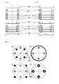
- Fig. 6a shows eight inner channels (21) of the second flow space, wherein the channels are alternately associated with the channel group of the fluid B and the channel group of the fluid C.
- Fig. 6b shows five channels of the second flow space in the form of four inner channels (21) (channel group fluid B) and a hollow cylindrical outer channel (221) (channel group fluid C).
- Fig. 6c shows four inner channels (21) and four outer channels (222) of the second flow space, wherein the inner channels (21) of the channel group of the fluid B and the outer channels (222) of the channel group of the fluid C are assigned.
- Fig. 6d shows four inner channels (21) of the second flow space, wherein the channels are designed as a tube-in-tube arrangement, the inner tube of the channel group of the fluid B and the outer tube of the channel group of the fluid C are assigned.
Landscapes
- Engineering & Computer Science (AREA)
- Physics & Mathematics (AREA)
- Thermal Sciences (AREA)
- Mechanical Engineering (AREA)
- General Engineering & Computer Science (AREA)
- Chemical & Material Sciences (AREA)
- Combustion & Propulsion (AREA)
- Fluid Mechanics (AREA)
- Geometry (AREA)
- Heat-Exchange Devices With Radiators And Conduit Assemblies (AREA)
Applications Claiming Priority (1)
| Application Number | Priority Date | Filing Date | Title |
|---|---|---|---|
| TR2008/08833A TR200808833A2 (tr) | 2008-11-19 | 2008-11-19 | Isı değiştiricileri ve ısı değiştiricili ısıtıcılar |
Publications (2)
| Publication Number | Publication Date |
|---|---|
| EP2189744A2 true EP2189744A2 (fr) | 2010-05-26 |
| EP2189744A3 EP2189744A3 (fr) | 2014-02-19 |
Family
ID=41719289
Family Applications (1)
| Application Number | Title | Priority Date | Filing Date |
|---|---|---|---|
| EP09176273.2A Withdrawn EP2189744A3 (fr) | 2008-11-19 | 2009-11-18 | Echangeur thermique et appareil de chauffage doté d'un échangeur thermique |
Country Status (2)
| Country | Link |
|---|---|
| EP (1) | EP2189744A3 (fr) |
| TR (1) | TR200808833A2 (fr) |
Citations (1)
| Publication number | Priority date | Publication date | Assignee | Title |
|---|---|---|---|---|
| EP1257770B1 (fr) | 2000-02-24 | 2004-11-24 | SWEP International AB | Dispositif pour le traitement catalytique de fluides |
Family Cites Families (4)
| Publication number | Priority date | Publication date | Assignee | Title |
|---|---|---|---|---|
| AU662456B2 (en) * | 1993-01-07 | 1995-08-31 | Arthur Maurice Meredith | A thermal oil heater |
| ITMO20020163A1 (it) * | 2002-06-13 | 2003-12-15 | Worgas Bruciatori Srl | Scambiatore di calore |
| SE527450C2 (sv) * | 2004-01-23 | 2006-03-07 | Alfa Laval Corp Ab | Värmeväxlare |
| JP5151373B2 (ja) * | 2006-11-30 | 2013-02-27 | 三浦工業株式会社 | ボイラ |
-
2008
- 2008-11-19 TR TR2008/08833A patent/TR200808833A2/xx unknown
-
2009
- 2009-11-18 EP EP09176273.2A patent/EP2189744A3/fr not_active Withdrawn
Patent Citations (1)
| Publication number | Priority date | Publication date | Assignee | Title |
|---|---|---|---|---|
| EP1257770B1 (fr) | 2000-02-24 | 2004-11-24 | SWEP International AB | Dispositif pour le traitement catalytique de fluides |
Also Published As
| Publication number | Publication date |
|---|---|
| TR200808833A2 (tr) | 2010-06-21 |
| EP2189744A3 (fr) | 2014-02-19 |
Similar Documents
| Publication | Publication Date | Title |
|---|---|---|
| EP3102899B1 (fr) | Appareil à écoulement permettant de guider un courant de fluide | |
| EP2584301B1 (fr) | Caloporteur à température élevée | |
| EP2440855B1 (fr) | Chaudière sectionnée | |
| EP3096105A1 (fr) | Systeme d'echangeur de chaleur de vehicule automobile | |
| DE102004046587B4 (de) | Wärmetauscher | |
| WO2023006132A1 (fr) | Échangeur de chaleur à plaques | |
| EP2313698B1 (fr) | Chaudière sectionnée en fonte ou en aluminium | |
| EP2507562A2 (fr) | Appareil de chauffage | |
| EP2438382B1 (fr) | Chaudière sectionnée | |
| EP4105552A1 (fr) | Brûleur récupérateur doté d'un récupérateur permettant de guider des fluides à contre-courant | |
| EP2085732B1 (fr) | Echangeur thermique en verre avec plaque tubulaire en plastique | |
| EP3730890B1 (fr) | Échangeur de chaleur à plaques | |
| DE1501657B1 (de) | Brennstoffbeheizter thermionischer Konverter | |
| EP2189744A2 (fr) | Echangeur thermique et appareil de chauffage doté d'un échangeur thermique | |
| EP0177904A2 (fr) | Dispositif pour l'échange de chaleur entre deux gaz en flux croisé | |
| DE29602990U1 (de) | Wasserheizer | |
| EP1624270B1 (fr) | Cellule thermique d'un appareil de chauffage | |
| DE3518344A1 (de) | Heizungskessel | |
| EP4235074B1 (fr) | Echangeur de chaleur | |
| DE102014015508B4 (de) | Wärmetauscherbausatz | |
| AT408146B (de) | Heizeinrichtung | |
| EP2395294B1 (fr) | Chaudière sectionnable | |
| DE3741798A1 (de) | Stahlheizkessel | |
| DE1501657C (de) | Brennstoffbeheizter thermionischer Konverter | |
| EP3250860B1 (fr) | Chaudière de chauffage |
Legal Events
| Date | Code | Title | Description |
|---|---|---|---|
| PUAI | Public reference made under article 153(3) epc to a published international application that has entered the european phase |
Free format text: ORIGINAL CODE: 0009012 |
|
| AK | Designated contracting states |
Kind code of ref document: A2 Designated state(s): AT BE BG CH CY CZ DE DK EE ES FI FR GB GR HR HU IE IS IT LI LT LU LV MC MK MT NL NO PL PT RO SE SI SK SM TR |
|
| PUAL | Search report despatched |
Free format text: ORIGINAL CODE: 0009013 |
|
| AK | Designated contracting states |
Kind code of ref document: A3 Designated state(s): AT BE BG CH CY CZ DE DK EE ES FI FR GB GR HR HU IE IS IT LI LT LU LV MC MK MT NL NO PL PT RO SE SI SK SM TR |
|
| RIC1 | Information provided on ipc code assigned before grant |
Ipc: F24H 1/40 20060101ALI20140114BHEP Ipc: F28F 9/24 20060101ALI20140114BHEP Ipc: F24H 1/30 20060101ALI20140114BHEP Ipc: F28D 21/00 20060101ALN20140114BHEP Ipc: F24H 1/44 20060101ALI20140114BHEP Ipc: F28D 9/00 20060101AFI20140114BHEP Ipc: F28D 7/16 20060101ALI20140114BHEP Ipc: F24H 1/24 20060101ALI20140114BHEP |
|
| 17P | Request for examination filed |
Effective date: 20140819 |
|
| RBV | Designated contracting states (corrected) |
Designated state(s): AT BE BG CH CY CZ DE DK EE ES FI FR GB GR HR HU IE IS IT LI LT LU LV MC MK MT NL NO PL PT RO SE SI SK SM TR |
|
| 17Q | First examination report despatched |
Effective date: 20161006 |
|
| STAA | Information on the status of an ep patent application or granted ep patent |
Free format text: STATUS: THE APPLICATION IS DEEMED TO BE WITHDRAWN |
|
| 18D | Application deemed to be withdrawn |
Effective date: 20170217 |