EP2190256B1 - Caloporteur - Google Patents
Caloporteur Download PDFInfo
- Publication number
- EP2190256B1 EP2190256B1 EP09175647.8A EP09175647A EP2190256B1 EP 2190256 B1 EP2190256 B1 EP 2190256B1 EP 09175647 A EP09175647 A EP 09175647A EP 2190256 B1 EP2190256 B1 EP 2190256B1
- Authority
- EP
- European Patent Office
- Prior art keywords
- electrical insulating
- conductor
- heat
- ptc
- heat exchanger
- Prior art date
- Legal status (The legal status is an assumption and is not a legal conclusion. Google has not performed a legal analysis and makes no representation as to the accuracy of the status listed.)
- Active
Links
Images

Classifications
-
- H—ELECTRICITY
- H05—ELECTRIC TECHNIQUES NOT OTHERWISE PROVIDED FOR
- H05B—ELECTRIC HEATING; ELECTRIC LIGHT SOURCES NOT OTHERWISE PROVIDED FOR; CIRCUIT ARRANGEMENTS FOR ELECTRIC LIGHT SOURCES, IN GENERAL
- H05B3/00—Ohmic-resistance heating
- H05B3/40—Heating elements having the shape of rods or tubes
- H05B3/42—Heating elements having the shape of rods or tubes non-flexible
- H05B3/48—Heating elements having the shape of rods or tubes non-flexible heating conductor embedded in insulating material
- H05B3/50—Heating elements having the shape of rods or tubes non-flexible heating conductor embedded in insulating material heating conductor arranged in metal tubes, the radiating surface having heat-conducting fins
-
- F—MECHANICAL ENGINEERING; LIGHTING; HEATING; WEAPONS; BLASTING
- F24—HEATING; RANGES; VENTILATING
- F24H—FLUID HEATERS, e.g. WATER OR AIR HEATERS, HAVING HEAT-GENERATING MEANS, e.g. HEAT PUMPS, IN GENERAL
- F24H3/00—Air heaters
- F24H3/02—Air heaters with forced circulation
- F24H3/04—Air heaters with forced circulation the air being in direct contact with the heating medium, e.g. electric heating element
- F24H3/0405—Air heaters with forced circulation the air being in direct contact with the heating medium, e.g. electric heating element using electric energy supply, e.g. the heating medium being a resistive element; Heating by direct contact, i.e. with resistive elements, electrodes and fins being bonded together without additional element in-between
-
- F—MECHANICAL ENGINEERING; LIGHTING; HEATING; WEAPONS; BLASTING
- F24—HEATING; RANGES; VENTILATING
- F24H—FLUID HEATERS, e.g. WATER OR AIR HEATERS, HAVING HEAT-GENERATING MEANS, e.g. HEAT PUMPS, IN GENERAL
- F24H3/00—Air heaters
- F24H3/02—Air heaters with forced circulation
- F24H3/04—Air heaters with forced circulation the air being in direct contact with the heating medium, e.g. electric heating element
- F24H3/0405—Air heaters with forced circulation the air being in direct contact with the heating medium, e.g. electric heating element using electric energy supply, e.g. the heating medium being a resistive element; Heating by direct contact, i.e. with resistive elements, electrodes and fins being bonded together without additional element in-between
- F24H3/0429—For vehicles
-
- F—MECHANICAL ENGINEERING; LIGHTING; HEATING; WEAPONS; BLASTING
- F24—HEATING; RANGES; VENTILATING
- F24H—FLUID HEATERS, e.g. WATER OR AIR HEATERS, HAVING HEAT-GENERATING MEANS, e.g. HEAT PUMPS, IN GENERAL
- F24H3/00—Air heaters
- F24H3/02—Air heaters with forced circulation
- F24H3/04—Air heaters with forced circulation the air being in direct contact with the heating medium, e.g. electric heating element
- F24H3/0405—Air heaters with forced circulation the air being in direct contact with the heating medium, e.g. electric heating element using electric energy supply, e.g. the heating medium being a resistive element; Heating by direct contact, i.e. with resistive elements, electrodes and fins being bonded together without additional element in-between
- F24H3/0429—For vehicles
- F24H3/0435—Structures comprising heat spreading elements in the form of fins
-
- F—MECHANICAL ENGINEERING; LIGHTING; HEATING; WEAPONS; BLASTING
- F24—HEATING; RANGES; VENTILATING
- F24H—FLUID HEATERS, e.g. WATER OR AIR HEATERS, HAVING HEAT-GENERATING MEANS, e.g. HEAT PUMPS, IN GENERAL
- F24H3/00—Air heaters
- F24H3/02—Air heaters with forced circulation
- F24H3/04—Air heaters with forced circulation the air being in direct contact with the heating medium, e.g. electric heating element
- F24H3/0405—Air heaters with forced circulation the air being in direct contact with the heating medium, e.g. electric heating element using electric energy supply, e.g. the heating medium being a resistive element; Heating by direct contact, i.e. with resistive elements, electrodes and fins being bonded together without additional element in-between
- F24H3/0429—For vehicles
- F24H3/0452—Frame constructions
-
- F—MECHANICAL ENGINEERING; LIGHTING; HEATING; WEAPONS; BLASTING
- F24—HEATING; RANGES; VENTILATING
- F24H—FLUID HEATERS, e.g. WATER OR AIR HEATERS, HAVING HEAT-GENERATING MEANS, e.g. HEAT PUMPS, IN GENERAL
- F24H3/00—Air heaters
- F24H3/02—Air heaters with forced circulation
- F24H3/04—Air heaters with forced circulation the air being in direct contact with the heating medium, e.g. electric heating element
- F24H3/0405—Air heaters with forced circulation the air being in direct contact with the heating medium, e.g. electric heating element using electric energy supply, e.g. the heating medium being a resistive element; Heating by direct contact, i.e. with resistive elements, electrodes and fins being bonded together without additional element in-between
- F24H3/0429—For vehicles
- F24H3/0452—Frame constructions
- F24H3/0476—Means for putting the electric heaters in the frame under strain, e.g. with springs
-
- F—MECHANICAL ENGINEERING; LIGHTING; HEATING; WEAPONS; BLASTING
- F24—HEATING; RANGES; VENTILATING
- F24H—FLUID HEATERS, e.g. WATER OR AIR HEATERS, HAVING HEAT-GENERATING MEANS, e.g. HEAT PUMPS, IN GENERAL
- F24H3/00—Air heaters
- F24H3/02—Air heaters with forced circulation
- F24H3/06—Air heaters with forced circulation the air being kept separate from the heating medium, e.g. using forced circulation of air over radiators
- F24H3/08—Air heaters with forced circulation the air being kept separate from the heating medium, e.g. using forced circulation of air over radiators by tubes
- F24H3/081—Air heaters with forced circulation the air being kept separate from the heating medium, e.g. using forced circulation of air over radiators by tubes using electric energy supply
- F24H3/082—The tubes being an electrical isolator containing the heater
-
- F—MECHANICAL ENGINEERING; LIGHTING; HEATING; WEAPONS; BLASTING
- F24—HEATING; RANGES; VENTILATING
- F24H—FLUID HEATERS, e.g. WATER OR AIR HEATERS, HAVING HEAT-GENERATING MEANS, e.g. HEAT PUMPS, IN GENERAL
- F24H9/00—Details
- F24H9/18—Arrangement or mounting of grates or heating means
- F24H9/1854—Arrangement or mounting of grates or heating means for air heaters
- F24H9/1863—Arrangement or mounting of electric heating means
- F24H9/1872—PTC resistor
-
- H—ELECTRICITY
- H05—ELECTRIC TECHNIQUES NOT OTHERWISE PROVIDED FOR
- H05B—ELECTRIC HEATING; ELECTRIC LIGHT SOURCES NOT OTHERWISE PROVIDED FOR; CIRCUIT ARRANGEMENTS FOR ELECTRIC LIGHT SOURCES, IN GENERAL
- H05B2203/00—Aspects relating to Ohmic resistive heating covered by group H05B3/00
- H05B2203/02—Heaters using heating elements having a positive temperature coefficient
Definitions
- the invention relates to a heat exchanger according to the preamble of claim 1 and a related automotive air conditioning system.
- Automotive air conditioning systems serve to heat and / or to cool the air to be supplied to the interior of a motor vehicle.
- electric heaters are used to heat the air supplied to the interior.
- the electric heater comprises a heat exchanger with a PTC element.
- Positive Temperature Coefficient (PTC) elements are current-carrying materials that have electrical resistance and conduct electricity better at lower temperatures than at higher temperatures. Their electrical resistance thus increases with increasing temperature.
- the PTC element is generally made of ceramic and is a PTC thermistor.
- a heat exchanger comprises a PTC element, at least two electrical conductors by means of which electrical current is passed through the PTC element and heat conducting elements, in particular lamellae, by means of which the surface for heating the air increases and thus the heat of the PTC element is transferred to the heat conducting element and the air.
- motor vehicles are produced which have an exclusive electric drive or a hybrid drive.
- Automotive air conditioning systems for these vehicles generally no longer have a heat exchanger for heating the air flowing through the cooling liquid. The entire heating power of the motor vehicle air conditioning system must therefore be applied by the electric heater.
- the PTC element with high voltage, z. B. in the range of 50 to 50 volts instead of low voltage with 12 volts to operate.
- High voltage in an automotive air conditioning system is a security problem because, for example, by a human touch of high voltage parts of the person from the high voltage health damage can be added.
- the US 4,327,282 shows a heat exchanger with a PTC heating element.
- Current is passed through the PTC heating element by means of contact plates and an insulating layer is arranged on the contact plates.
- the components are held together by means of a U-shaped clip.
- a heat generating element of a heater for air heating comprising at least one PTC element and voltage applied to opposite side surfaces of the PTC element electrical conductor tracks, wherein the two electrical conductors are surrounded on the outside by a non-electrically conductive insulating layer.
- the EP 1 768 457 A1 discloses a heat generating element of a heating device, wherein the heat generating element comprises a PTC element, which is arranged between electrical conductor tracks. For safety against electrical flashovers and leakage currents, an insulating gap is provided between a positioning frame and the PTC element.
- the US Pat. No. 6,178,292 B1 discloses a fluid-flow radiator with an electric heater disposed thereon.
- the EP 2 023 056 A1 discloses a connection process for an air heater.
- the object of the present invention is to provide a heat exchanger and a motor vehicle air conditioning system in which a with electric current under high voltage, for. B. more than 50 V, operated heat exchanger without endangering the environment, especially people, can be operated.
- the heat exchanger and the motor vehicle air conditioning should be inexpensive to manufacture and work reliably in operation.
- this heat exchanger comprises at least one PTC element, at least two conductors electrically connected to the at least one PTC element, in particular printed circuit boards, in order to conduct electrical current through the at least one PTC element and thereby the PTC element to heat and at least one heat conducting element for transferring heat from the at least one PTC element to a fluid to be heated and at least one means, for.
- adhesive or a mechanical pressure load for.
- a clip or a spring for connecting the at least one PTC element, the at least two conductors and the at least one heat-conducting element with one another, wherein at least one heat-conducting element is electrically insulated from at least one conductor by means of at least one first electrical insulating element.
- the at least one first electrical insulating element is arranged between at least one conductor and at least one heat-conducting element, and at least one second electrical insulating element electrically insulates at least one PTC element and at least one conductor, wherein the at least one first electrical insulating element consists of a different material as the at least one second electrical insulating element.
- the at least one second electrical insulating element is in, preferably immediate, contact with the at least one PTC element and / or the at least one conductor and / or the at least one heat-conducting element, in particular a heat-conducting plate of the heat-conducting element.
- the at least one second electrical insulating element is a hardenable or hardened fluid or gel, for. B. an adhesive, in particular silicone adhesive, or an insulating gel or fluid.
- the fluid or gel is electrically isolated.
- the at least one PTC element and the at least one conductor in particular exclusively, material and / or positive and / or non-positive, z. B. by means of adhesive and / or a mechanical pressure loading means, for.
- a spring connected to each other and / or the at least one heat conducting element and the at least one first electrical insulating element, in particular exclusively, material and / or form and / or force fit, z. B. by means of adhesive and / or a mechanical pressure loading means, for.
- As a spring connected to each other and / or the at least one conductor and the at least one first electrical insulating element, in particular exclusively, material and / or positive and / or non-positive, z. B. by means of adhesive and / or a mechanical pressure loading means, for.
- a cohesive connection has the advantage that as a means for connecting the components of the heat exchanger, d. H. the at least one PTC element, the at least two conductors and the at least one heat conducting element, no complex holding device, for. As a clip or a frame is required. As a means for connecting thus serves the material which produces the cohesive connection.
- the at least one second electrical insulation element isolates the at least one PTC element and the at least one conductor in those regions and covers a surface thereof in which the at least one PTC element or the at least one conductor does not make contact or connection to the at least one PTC element or the at least one conductor or the at least one heat conducting element or the at least one first electrical insulating element is.
- the at least one second insulating element is at least partially enclosed or covered by a frame profile and / or the first electrical insulating element and / or the heat conducting plate.
- the at least one first electrical insulating element comprises ceramic and / or plastic, for. As polyimide, and / or a mineral, for. B. MICA, and / or the at least one first electrical insulating element is a film, a plate or a coating.
- the at least one second electrical insulating element is introduced by means of injection into a cavity for insulating and / or the at least one second electrical insulating element is an adhesive, for. Silicone adhesive, and an excess of adhesive is in the cavity due to bonding of the at least one PTC element and / or the at least one conductor and / or the at least one first insulating element and / or the at least one heat conducting element, in particular the heat conducting plate of the heat-conducting element, pressed together by means of the adhesive.
- An automotive air conditioning system comprises at least one heat exchanger described in this application.
- a method for producing a heat exchanger is formed with the steps: provide at least one PTC element, provide at least two electrical conductors, in particular printed circuit boards, for passing electrical current through the at least a PTC element, providing at least one slaughtertelements for transmitting heat from the at least one PTC element to a fluid to be heated, connecting the at least two conductors to the at least one PTC element, connecting the at least one blanketleitides with at least one conductor and / or at least one PTC element, wherein at least a first electrical insulating element is provided and the at least one first electrical insulating element is connected to at least one conductor and / or at least one heat conducting element to at least one blanketleitelem ent electrically isolate from at least one conductor.
- the at least one first electrical insulating element with at least one conductor and / or at least one heat conducting element preferably exclusively, material and / or positive and / or non-positive, z. B. by means of adhesive and / or a mechanical pressure loading means, for. B. a spring connected.
- At least one in particular as, preferably hardenable and / or hardened, fluid or, preferably hardenable and / or hardened gel or Isoliergel or fluid formed, second electrical insulating element, for.
- an adhesive in particular silicone adhesive, on the at least one PTC element and / or the at least one conductor and / or the at least one heat conducting element, in particular a heat conducting plate of the heat conducting, applied, in particular by means of spraying, pumping or pressing, so that Preferably, the at least one second electrical insulating element, the at least one PTC element and / or the at least one conductor and / or the at least one heat conducting element, in particular the heat conducting plate of the heat conducting element, at least partially electrically isolated in those areas in which the at least one PTC element and / or the at least one conductor and / or the at least one heat-conducting element not in mediate, z. B. by means of an adhesive, or in direct contact with the at least one PTC element and
- the at least one second electrical insulating element is an adhesive for connecting the at least one PTC element and / or the at least one conductor and / or the at least one first insulating element and / or the at least one heat-conducting element, in particular a heat-conducting plate of the heat-conducting element, with each other and by means of the adhesive, the at least one PTC element and / or the at least one conductor and / or the at least one heat-conducting element, in particular a heat-conducting plate of the heat-conducting element, are connected to one another in a material-locking manner.
- an excess of adhesive is applied to the at least one PTC element and / or the at least one conductor and / or the at least one first insulating element and / or the at least one heat-conducting element as is necessary for the connection and during the integral connection, d. H.
- the excess is pressed or pressed on the at least one PTC element and / or the at least one conductor and / or the at least one heat conducting element, so that preferably the at least one second electrical insulating element, the at least one PTC element and / or at least a conductor and / or the at least one heat-conducting element, in particular the heat-conducting plate of the heat-conducting element, at least partially electrically insulated in those areas in which the at least one PTC element and / or the at least one conductor and / or the at least one heat-conducting element are not indirectly, z. B. by means of an adhesive, or in direct contact with the at least one PTC element and / or the at least one conductor and / or the at least one first insulating element and / or the at least one heat conducting element.
- the at least one first insulating element is connected differently to the heat exchanger than the at least one second insulating element.
- the at least one first insulating element is introduced differently into the heat exchanger than the at least one second insulating element.
- the heating of the air takes place exclusively by means of at least one electrical Heating device, in particular a described in this application heat exchanger with a PTC element.
- the at least one first and / or the at least one second heat-conducting element has a thermal conductivity of at least 1 W / mK, in particular at least 30 W / mK.
- the at least one first and / or the at least one second insulating element has an electrical insulation of at least 1 kV / mm, in particular at least 25 kV / mm.
- the at least one first and / or the at least one second insulating element has a dielectric strength of at least 1 kV in cross-section.
- the at least one first and / or the at least one second insulating element has a thermal conductivity of at least 1 W / mK, in particular at least 25 W / mK.
- the at least one first and / or the at least one second insulating element can thus on the one hand good electrical insulation and on the other hand, sufficiently good to conduct the heat from the PTC element to the heat-conducting element.
- the at least one first insulating element is at least two parts.
- the at least one first insulating element may comprise, for example, a foil and a plate.
- the plate has a sufficiently high rigidity and is therefore not easily bendable as the film.
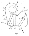
- Fig. 1 shows an automotive air conditioning system 7.
- an air conditioning housing 9 with a bottom wall 10 and an outlet opening 12, a fan 8, a filter 13, a refrigerant evaporator 14 and an electric heater 15 is arranged.
- the air conditioning housing 9 thus forms a channel 18 for passing the air.
- Walls 11 of the air conditioning housing 9 have on the inside a surface 19 which define the channel 18.
- the air for the interior of a motor vehicle is passed by means of the blower 8 through the filter 13, the refrigerant evaporator 14 and the electric heater 15.
- the motor vehicle air conditioning system 7 is thus not provided with a heat exchanger through which coolant flows for heating the air conducted through the motor vehicle system 7.
- the air conducted by the automotive air conditioning system 7 is heated exclusively by means of the electric heater 15.
- the motor vehicle air conditioning system 7 is preferably in a Motor vehicle with exclusively electric drive or with a hybrid drive used (not shown). In order to achieve the necessary heating power by means of the electric heater 15, the electric heater 15 with high voltage, z. B. with more than 50 volts, operated.
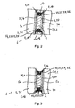
- Fig. 2 is a first embodiment of the designed as a heat exchanger 6 electric heater 15 of the motor vehicle air conditioning 7 shown.
- the heat exchanger 6 comprises a plate-shaped PTC element 1 made of ceramic, a first printed circuit board 3 and a second printed circuit board 4 in each case as a conductor 20 in order to be able to conduct electrical current through the PTC element 1.
- Corrugated ribs 21 as heat-conducting elements 2 conduct the heat generated in the PTC element 1 due to the electrical resistance of the PTC element 1 to the air conducted by the motor vehicle air conditioning system 7.
- the corrugated fins 21 are attached to a heat conducting plate 16.
- the corrugated fins 21 increase the surface area available to transfer heat to the air.
- the two printed circuit boards 3, 4 are glued to the PTC element 1.
- the heat-conducting elements 2 and the conductors 20 are made of metal, for. B. aluminum.
- connection or the contact between the corrugated fins 21 or the heat-conducting plate 16 as part of the heat-conducting element 2 and the printed circuit boards 3, 4 takes place indirectly with a first insulating element 5a.
- the first electrical insulating element 5a is made of plastic, for. As polyimide, ceramics or minerals, z. As MICA, or other material with a sufficiently good thermal conductivity to conduct the heat from the PTC element 1 to the corrugated fins 21 and on the other hand has a sufficiently good electrical insulation to the corrugated fins 21 from the high-voltage printed circuit board 3rd 4 to electrically isolate and thereby upon contact with the corrugated fins 21 an electric shock Person to be able to prevent.
- the first insulating 5a while cover a broad side of the circuit boards 3, 4 completely, so that the circuit boards 3, 4 only in those areas must be additionally insulated, where the circuit boards 3, 4 not with the first insulating 5a and the PTC element 1 in contact.
- the printed circuit boards 3, 4 are materially connected to the first insulating member 5a by means of adhesive 23. This also applies to the connection between the first insulating member 5a and the heat conducting plate 16 and the connection between the PTC element 1 and the first and second printed circuit board 3, 4th
- a second electrical insulating element 5 b is introduced in a cavity 22 which is essentially enclosed by a frame profile 17, the PTC element 1, the two circuit boards 3, 4, the two first insulating elements 5a and the two heat conducting plates 16, a second electrical insulating element 5 b is introduced.
- the second electrical insulating element 5 b is a, in particular hardenable or hardened, fluid or gel, for. As in the second electrical insulating 5 b is usually no sufficiently high thermal conductivity required as in the first insulating 5 a, because by the second electrical insulating 5 b in the Substantially no heat or only a small amount of heat must be conducted to the heat-conducting element 2.
- the second electrical insulating element 5 b has a sufficiently high electrical insulation.
- the second insulating member 5 b can be introduced into the cavity 22 in various ways.
- the insulating gel 24 or an adhesive 23 is injected or pumped into the cavity 22 through openings in the frame profile 17 or openings in the region of the frame profile 17.
- the insulating gel 24 or the adhesive 23 with the properties of a fluid and a high viscosity thereby adapts to the boundary surfaces of the cavity 22, formed essentially by the frame profile 17, the PTC element 1, the two circuit boards 3, 4, the two first insulating 5a and the two heat conducting plates 16, substantially completely, so that the cavity 22 is completely filled by the adhesive 23 or the insulating gel 24.
- the PTC element 1 and the two circuit boards 3, 4 are completely electrically insulated from the environment, because in the other areas, the PTC element 1 with the circuit boards 3, 4 are in communication and the two circuit boards 3, 4 with the PTC element 1 and the first electrical insulating 5a is indirectly or directly in communication. Due to the complete, void-free filling of the cavity 22 with the adhesive 23 or the insulating gel 24, the PTC element and the two circuit boards 3, 4 are sealed fluid-tight in the heat exchanger 6, so that in general no leakage currents occur on the outside of the heat exchanger 6 or touching the heat exchanger 6, even with moisture on the surface of the heat exchanger 6, no danger.
- the insulating gel 24 is designed to the effect that it can not leak after introduction into the cavity 22 by either the insulating gel 24 has a sufficiently high viscosity or the viscosity is increased upon contact with air or the insulating gel 24 at the in with in Contact area slightly hardened.
- the cavity 22 with the environment only with an opening, for. B. in the frame profile 17, connected.
- the adhesive 23 or the insulating gel 24 and the insulating fluid 24 is injected and then the opening fluid-tight, z. B. by means of a plug, closed.
- a hardening of the adhesive 23 or a sufficiently high viscosity of the insulating fluid 24 is not required (not shown).
- the second insulating member 5 b is a solid as the first insulating member 5 a.
- the second insulating 5 b has exactly the complementary shape to the cavity 22, so that the second insulating 5 b only in the cavity 22 must be inserted.
- the connection between the second insulating 5 b as a solid and the cavity 22 is material and / or kraftund / or positive fit.
- a thin layer of adhesive 23 is applied to the second electrical insulating element 5 b and / or the second insulating element 5 b is clamped between the frame profile 17 and the PTC element 1 and the two printed circuit boards 3, 4 (not shown).
- the first insulating 5 a made of plastic and is connected by means of encapsulation of the first and second circuit board 3, 4 with the first and second circuit board 3, 4.
- a circuit board 3, 4 is inserted into an injection mold and then introduced into the injection mold, preferably thermoplastic, plastic.
- the first insulating 5 a plastic is thus directly connected to the first and second circuit board 3, 4.
- the first insulating 5 a with the first and second circuit board 3, 4 can be applied to the first or second circuit board 3, 4 adhesive before introducing the first or second circuit board 3, 4 in the injection mold (not shown).
- the PTC element 1 is connected to the two circuit boards 3, 4 in the first embodiment according to Fig. 2 connected by adhesive 23 and the two circuit boards 3, 4 are also connected by means of adhesive 23 to the first insulating 5a.
- This adhesive 23 for the cohesive connection is not shown in the figures.
- an excess of adhesive 23 is applied to the PTC element 1, so that when connecting the PTC element 1 to the circuit board 3, 4 of the Excess, which is not required for the cohesive connection, is pressed or pressed into the cavity 22 while the PTC element 1 is pressed onto the printed circuit board 3, 4.
- the excess of adhesive 23 is dimensioned such that the cavity 22 is completely filled on both narrow sides of the PTC element 1.
- the adhesive 23 hardens after the connection in the cavity 22, so that the adhesive 23 can no longer leak from the cavity 22 and a permanent insulation of the electric current standing parts 1, 3, 4 is ensured.
- a second embodiment of the heat exchanger 6 is shown.
- the heat exchanger 6 is not provided with a frame profile 17, so that the cavity 22 has no boundary on an outer side.
- the adhesive 23 or the insulating fluid 24 must have a sufficient hardness or viscosity after introduction into the cavity 22, that the cavity 22 is permanently filled with the adhesive 23 or the insulating fluid 24 as a second electrical insulating element 5 b.
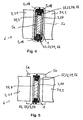
- Fig. 4 a third embodiment of the heat exchanger 6 is shown.
- the cavity 22 is covered by the heat-conducting plate 16 of the heat-conducting element 2.
- the heat conducting plate 16, on which the corrugated fins 21 are fixed, is formed in the end region in cross-section arcuate or L-shaped.
- the heat-conducting plates 16 are electrically insulated from the two printed circuit boards 3, 4 by means of the first electrical insulating element 5 a, so that no danger to the environment can emanate from the two heat-conducting plates 16.
- Fig. 5 a third embodiment of the heat exchanger 6 is shown.
- the frame profile 17 covers a in the end region in cross-section T-shaped first insulating member 5 a the cavity 22 partially from.
- the corrugated fins 21 are attached directly to the first insulating 5 a without a heat conducting plate 16.
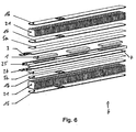
- Fig. 6 is an exploded view of the heat exchanger 6 without the second electrical insulating element 5 b shown.
- PTC elements 1 are fastened or fixed in recesses of a fixing plate 25.
- the first insulating 5 a, printed circuit boards 3, 4 and corrugated fins 21 with heat conducting plates 16 are arranged one above the other like a layer.
- the two printed circuit boards 3, 4 are connected only by means of electrical contacts 26 or electrical lines to the surroundings of the heat exchanger 6 in order to be able to conduct electrical current through the two printed circuit boards 3, 4 and thus the PTC element 1.
- heat exchanger 6 are stacked one above the other (not shown).
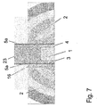
- Fig. 7 is a further embodiment of a heat exchanger 6 according to the invention shown.
- the first insulating 5a has a projection with respect to the heat conducting plates 16.
- the gap formed by the supernatant is completely filled with adhesive 23.
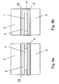
- FIG. 8a and 8b two further embodiments of a heat exchanger 6 according to the invention are shown.
- the circuit boards 3, 4 are completely encapsulated with an adhesive.
- the PTC elements 1 can either be held in a frame 17 (see Fig. 8b ), or it can also be dispensed with the frame (see Fig. 8a ).
- Fig. 9 is a further embodiment of a heat exchanger 6 according to the invention shown.
- both the PTC elements 1, and the two circuit boards 3, 4 and the heat-conducting elements 2 are surrounded by insulation.
- the insulation may be provided, for example, by a surface treatment in an insulating bath.
- the cohesive connection between the PTC elements and the two printed circuit boards 3 and 4 or between the heat-conducting elements 2 and the two printed circuit boards 3 and 4 is provided by an adhesive.
- the PTC element 1 and the two printed circuit boards 3, 4 are substantially completely electrically isolated from the environment, so that the high voltage can not pose any danger to the environment.
Landscapes
- Engineering & Computer Science (AREA)
- Physics & Mathematics (AREA)
- Thermal Sciences (AREA)
- Chemical & Material Sciences (AREA)
- Combustion & Propulsion (AREA)
- Mechanical Engineering (AREA)
- General Engineering & Computer Science (AREA)
- Air-Conditioning For Vehicles (AREA)
Claims (7)
- Echangeur de chaleur (6) comprenant- au moins un élément - CTP - à coefficient de température positif (1),- au moins deux conducteurs (20) reliés de façon électroconductrice à l'élément CTP (1) au moins au nombre de un, pour fournir du courant électrique à travers l'élément CTP (1) au moins au nombre de un et, en procédant ainsi, permettant de chauffer l'élément CTP (1), et- au moins un élément conducteur de la chaleur (2) servant à la transmission de chaleur provenant de l'élément CTP (1) au moins au nombre de un, à un fluide à chauffer, et- au moins un moyen servant à assembler les uns aux autres l'élément CTP (1) au moins au nombre de un, les conducteurs (20) au moins au nombre de deux et l'élément conducteur de la chaleur (2) au moins au nombre de un,
où au moins un élément conducteur de la chaleur (2) est isolé électriquement au moins d'un conducteur (20), au moyen au moins d'un premier élément isolant électrique (5a),
caractérisé en ce que
le premier élément isolant électrique (5a) au moins au nombre de un est disposé entre au moins un conducteur (20) et au moins un élément conducteur de la chaleur (2), et comprend une plaque ou un revêtement en céramique, ou bien une feuille ou un revêtement en matière plastique, ou bien une plaque ou un revêtement se composant d'un minéral, et où il est prévu au moins un deuxième élément isolant électrique (5b) qui isole électriquement l'élément CTP (1) au moins au nombre de un et le conducteur (20) au moins au nombre de un et
le premier élément isolant électrique (5a) au moins au nombre de un se compose d'un matériau autre que celui du deuxième élément isolant électrique (5b) au moins au nombre de un, et où
le deuxième élément isolant électrique (5b) au moins au nombre de un est un fluide ou gel durcissable ou durci, et
le deuxième élément isolant électrique (5b) au moins au nombre de un isole électriquement l'élément CTP (1) au moins au nombre de un et le conducteur (20) au moins au nombre de un dans des zones et recouvre une surface de ces éléments, lesdites zones étant celles dans lesquelles l'élément CTP (1) au moins au nombre de un ou le conducteur (20) au moins au nombre de un n'est pas en contact ou en liaison avec l'élément CTP (1) au moins au nombre de un ou avec le conducteur (20) au moins au nombre de un ou avec l'élément conducteur de la chaleur (2) au moins au nombre de un ou avec le premier élément isolant électrique (5a) au moins au nombre de un. - Echangeur de chaleur selon la revendication 1, caractérisé en ce que le deuxième élément isolant électrique (5b) au moins au nombre de un est en contact avec l'élément CTP (1) au moins au nombre de un ou avec le conducteur (20) au moins au nombre de un ou avec l'élément conducteur de la chaleur (2) au moins au nombre de un.
- Echangeur de chaleur selon l'une des revendications précédentes, caractérisé en ce que l'élément CTP (1) au moins au nombre de un et le conducteur (20) au moins au nombre de un sont assemblés l'un à l'autre par complémentarité de matière ou de forme ou bien par action de force, et l'élément conducteur de la chaleur (2) au moins au nombre de un et le premier élément isolant électrique (5a) au moins au nombre de un sont assemblés l'un à l'autre par complémentarité de matière ou de forme ou bien par action de force, et le conducteur (20) au moins au nombre de un et le premier élément isolant électrique (5a) au moins au nombre de un sont assemblés l'un à l'autre par complémentarité de matière ou de forme ou bien par action de force.
- Echangeur de chaleur selon l'une quelconque des revendications précédentes, caractérisé en ce que le deuxième élément isolant (5b) au moins au nombre de un est entouré ou recouvert au moins partiellement par un profilé de cadre (17) ou par le premier élément isolant électrique (5a) ou par la plaque conductrice de la chaleur (16).
- Echangeur de chaleur selon l'une quelconque des revendications précédentes 1 à 4, caractérisé en ce que le deuxième élément isolant électrique (5b) au moins au nombre de un servant à l'isolation est introduit dans un espace creux (22), par injection.
- Echangeur de chaleur selon l'une quelconque des revendications précédentes 1 à 4, caractérisé en ce que le deuxième élément isolant électrique (5b) au moins au nombre de un est une colle (23), et un excédent de colle (23) est comprimé dans l'espace creux (22), en raison d'un assemblage de l'élément CTP (1) au moins au nombre de un ou du conducteur (20) au moins au nombre de un ou du premier élément isolant électrique (5a) au moins au nombre de un ou de l'élément conducteur de la chaleur (2) au moins au nombre de un, lesdits éléments étant assemblés les uns aux autres au moyen de la colle (23).
- Système de climatisation d'un véhicule automobile, caractérisé en ce que le système de climatisation d'un véhicule automobile comprend au moins un échangeur de chaleur (6) selon l'une quelconque ou plusieurs des revendications précédentes.
Priority Applications (1)
| Application Number | Priority Date | Filing Date | Title |
|---|---|---|---|
| EP09175647.8A EP2190256B2 (fr) | 2008-11-20 | 2009-11-11 | Caloporteur |
Applications Claiming Priority (2)
| Application Number | Priority Date | Filing Date | Title |
|---|---|---|---|
| EP08291088A EP2190258A1 (fr) | 2008-11-20 | 2008-11-20 | Caloporteur |
| EP09175647.8A EP2190256B2 (fr) | 2008-11-20 | 2009-11-11 | Caloporteur |
Publications (3)
| Publication Number | Publication Date |
|---|---|
| EP2190256A1 EP2190256A1 (fr) | 2010-05-26 |
| EP2190256B1 true EP2190256B1 (fr) | 2016-11-02 |
| EP2190256B2 EP2190256B2 (fr) | 2024-04-24 |
Family
ID=40445743
Family Applications (2)
| Application Number | Title | Priority Date | Filing Date |
|---|---|---|---|
| EP08291088A Withdrawn EP2190258A1 (fr) | 2008-11-20 | 2008-11-20 | Caloporteur |
| EP09175647.8A Active EP2190256B2 (fr) | 2008-11-20 | 2009-11-11 | Caloporteur |
Family Applications Before (1)
| Application Number | Title | Priority Date | Filing Date |
|---|---|---|---|
| EP08291088A Withdrawn EP2190258A1 (fr) | 2008-11-20 | 2008-11-20 | Caloporteur |
Country Status (1)
| Country | Link |
|---|---|
| EP (2) | EP2190258A1 (fr) |
Families Citing this family (21)
| Publication number | Priority date | Publication date | Assignee | Title |
|---|---|---|---|---|
| EP2393336B1 (fr) * | 2010-06-04 | 2017-05-17 | Mahle Behr France Rouffach S.A.S | Caloporteur |
| EP2397788A1 (fr) * | 2010-06-17 | 2011-12-21 | Behr GmbH & Co. KG | Caloporteur et procédé de fabrication d'un tel caloporteur |
| DE102010037132A1 (de) * | 2010-08-24 | 2012-03-01 | Webasto Ag | Elektrische Fahrzeug-Heizvorrichtung |
| EP2428746B8 (fr) | 2010-09-13 | 2021-12-29 | MAHLE Behr GmbH & Co. KG | Echangeur de chaleur |
| EP2428747B2 (fr) | 2010-09-13 | 2024-10-30 | MAHLE Behr GmbH & Co. KG | Echangeu de chaleur |
| FR2966580B1 (fr) * | 2010-10-20 | 2014-01-03 | Valeo Systemes Thermiques | Echangeur de chaleur et installation de ventilation et de chauffage correspondante |
| DE102011003296A1 (de) * | 2011-01-28 | 2012-08-02 | Behr Gmbh & Co. Kg | Wärmeübertrager |
| DE102011077922B4 (de) † | 2011-06-21 | 2024-10-10 | Mahle International Gmbh | Wärmeübertrager |
| EP2608633B1 (fr) * | 2011-12-22 | 2020-08-26 | Eberspächer catem GmbH & Co. KG | Elément générateur de chaleur |
| EP2607808B1 (fr) | 2011-12-22 | 2017-09-27 | Eberspächer catem GmbH & Co. KG | Elément générateur de chaleur |
| DE102012013770A1 (de) | 2012-07-11 | 2014-01-16 | Eberspächer Catem Gmbh & Co. Kg | Wärme erzeugendes Element |
| EP2731400A1 (fr) * | 2012-11-12 | 2014-05-14 | Betacera Inc. | Appareil de chauffage électrique avec mécanisme imperméable à l'eau |
| EP2731399A1 (fr) * | 2012-11-12 | 2014-05-14 | Betacera Inc. | Élément chauffant isolé |
| EP3073801A1 (fr) * | 2015-03-26 | 2016-09-28 | Betacera Inc. | Dispositif chauffant formé d'un seul tenant |
| EP3101999B1 (fr) * | 2015-06-02 | 2021-03-17 | Eberspächer catem GmbH & Co. KG | Élement de chauffage a coefficient de temperature positif (ctp) et dispositif de chauffage electrique pour un vehicule automobile comprenant un tel element de chauffage ctp |
| DE102016125124A1 (de) * | 2016-12-21 | 2018-06-21 | Dbk David + Baader Gmbh | Entladewiderstand |
| DE102018212012A1 (de) | 2018-07-18 | 2020-01-23 | Eberspächer Catem Gmbh & Co. Kg | Wärmeerzeugendes Element und Verfahren zu dessen Herstellung |
| DE102019205848A1 (de) | 2019-04-24 | 2020-10-29 | Eberspächer Catem Gmbh & Co. Kg | PTC-Heizelement und elektrische Heizvorrichtung mit einem solchen PTC-Heizelement und Verfahren zur Herstellung eines PTC-Heizelementes |
| DE102019217234A1 (de) | 2019-11-07 | 2021-05-12 | Eberspächer Catem Gmbh & Co. Kg | PTC-Heizeinrichtung und elektrische Heizvorrichtung mit einer solchen PTC- Heizeinrichtung und Verfahren zur Herstellung einer elektrischen Heizvorrichtung |
| DE102020120472B4 (de) * | 2020-08-04 | 2025-11-06 | Eberspächer catem Hermsdorf GmbH & Co. KG | Verfahren zur Herstellung eines PTC-Heizelements |
| DE102022107554A1 (de) * | 2022-03-30 | 2023-10-05 | Eberspächer Catem Gmbh & Co. Kg | PTC-Heizeinrichtung und elektrische Heizvorrichtung umfassend eine solche |
Citations (10)
| Publication number | Priority date | Publication date | Assignee | Title |
|---|---|---|---|---|
| DE2804749A1 (de) | 1978-02-04 | 1979-08-09 | Eichenauer Fa Fritz | Durchlauferhitzer |
| DE3151109A1 (de) | 1980-12-26 | 1982-07-08 | Matsushita Electric Industrial Co., Ltd., Kadoma, Osaka | Thermistor-heizeinrichtung und verfahren zu dessen herstellung |
| DE8503272U1 (de) | 1985-02-06 | 1985-05-23 | Fritz Eichenauer GmbH & Co KG, 6744 Kandel | Elektrischer heizkoerper |
| DE2804818C2 (de) | 1978-02-04 | 1986-12-11 | Fritz Eichenauer GmbH & Co KG, 6744 Kandel | Elektrische Heizeinrichtung |
| US5192853A (en) | 1991-10-22 | 1993-03-09 | Yeh Yuan Chang | Heating set having positive temperatue coefficient thermistor elements adhesively connected to heat radiator devices |
| US6178292B1 (en) | 1997-02-06 | 2001-01-23 | Denso Corporation | Core unit of heat exchanger having electric heater |
| EP1515587B1 (fr) | 2003-09-11 | 2006-12-13 | Catem GmbH & Co. KG | Dispositif de chauffage électrique muni d'un élément chauffant scellé |
| EP1768457A1 (fr) | 2005-09-23 | 2007-03-28 | Catem GmbH & Co.KG | Element chauffant d'un dispositif de chauffage |
| EP1768459B1 (fr) | 2005-09-23 | 2008-05-21 | Catem GmbH & Co. KG | Elément chauffant d'un dispositif de chauffage |
| EP2023056A1 (fr) | 2007-07-30 | 2009-02-11 | Chia-Hsiung Wu | Procédé de liaison pour un chauffage d'air et structure de celui-ci |
Family Cites Families (2)
| Publication number | Priority date | Publication date | Assignee | Title |
|---|---|---|---|---|
| DE2845965C2 (de) | 1978-10-21 | 1983-01-20 | Fritz Eichenauer GmbH & Co KG, 6744 Kandel | Elektrisches Widerstandsheizelement |
| EP1916874B1 (fr) | 2005-09-23 | 2010-11-24 | Eberspächer catem GmbH & Co. KG | Elément d'un dispositif de chauffage produisant de la chaleur |
-
2008
- 2008-11-20 EP EP08291088A patent/EP2190258A1/fr not_active Withdrawn
-
2009
- 2009-11-11 EP EP09175647.8A patent/EP2190256B2/fr active Active
Patent Citations (10)
| Publication number | Priority date | Publication date | Assignee | Title |
|---|---|---|---|---|
| DE2804749A1 (de) | 1978-02-04 | 1979-08-09 | Eichenauer Fa Fritz | Durchlauferhitzer |
| DE2804818C2 (de) | 1978-02-04 | 1986-12-11 | Fritz Eichenauer GmbH & Co KG, 6744 Kandel | Elektrische Heizeinrichtung |
| DE3151109A1 (de) | 1980-12-26 | 1982-07-08 | Matsushita Electric Industrial Co., Ltd., Kadoma, Osaka | Thermistor-heizeinrichtung und verfahren zu dessen herstellung |
| DE8503272U1 (de) | 1985-02-06 | 1985-05-23 | Fritz Eichenauer GmbH & Co KG, 6744 Kandel | Elektrischer heizkoerper |
| US5192853A (en) | 1991-10-22 | 1993-03-09 | Yeh Yuan Chang | Heating set having positive temperatue coefficient thermistor elements adhesively connected to heat radiator devices |
| US6178292B1 (en) | 1997-02-06 | 2001-01-23 | Denso Corporation | Core unit of heat exchanger having electric heater |
| EP1515587B1 (fr) | 2003-09-11 | 2006-12-13 | Catem GmbH & Co. KG | Dispositif de chauffage électrique muni d'un élément chauffant scellé |
| EP1768457A1 (fr) | 2005-09-23 | 2007-03-28 | Catem GmbH & Co.KG | Element chauffant d'un dispositif de chauffage |
| EP1768459B1 (fr) | 2005-09-23 | 2008-05-21 | Catem GmbH & Co. KG | Elément chauffant d'un dispositif de chauffage |
| EP2023056A1 (fr) | 2007-07-30 | 2009-02-11 | Chia-Hsiung Wu | Procédé de liaison pour un chauffage d'air et structure de celui-ci |
Also Published As
| Publication number | Publication date |
|---|---|
| EP2190256B2 (fr) | 2024-04-24 |
| EP2190258A1 (fr) | 2010-05-26 |
| EP2190256A1 (fr) | 2010-05-26 |
Similar Documents
| Publication | Publication Date | Title |
|---|---|---|
| EP2190256B2 (fr) | Caloporteur | |
| EP2724086B1 (fr) | Échangeur de chaleur | |
| EP2211590B1 (fr) | Echangeur de chaleur | |
| EP2428746B1 (fr) | Echangeur de chaleur | |
| EP2428747B1 (fr) | Echangeur de chaleur | |
| EP2395295B1 (fr) | Echangeur de chaleur | |
| US10524310B2 (en) | PTC heating element and electric heating device for an automotive vehicle comprising such a PTC heating element | |
| EP1768458B1 (fr) | Elément chauffant d'un dispositif de chauffage | |
| WO2008049619A1 (fr) | Élément producteur de chaleur pour un dispositif de chauffage électrique, et son procédé de fabrication | |
| EP2397788A1 (fr) | Caloporteur et procédé de fabrication d'un tel caloporteur | |
| EP2346304B1 (fr) | Caloporteur | |
| EP2395296B1 (fr) | Echangeur de chaleur | |
| EP2276321B1 (fr) | Caloporteur | |
| DE102010048593B4 (de) | Modulare Heizvorrichtung | |
| WO2009083107A1 (fr) | Dispositif de chauffage | |
| EP2190257A1 (fr) | Caloporteur | |
| EP2296432B1 (fr) | Caloporteur | |
| DE102020202195A1 (de) | Elektrische Heizeinrichtung | |
| EP2474793B1 (fr) | Échangeur de chaleur | |
| EP2293648A1 (fr) | Caloporteur | |
| DE102022203470A1 (de) | Elektrischer Durchlauferhitzer und Verfahren zur Herstellung des elektrischen Durchlauferhitzers | |
| EP1696181A1 (fr) | Radiateur avec un élément de chauffage électrique externe | |
| EP3340258A1 (fr) | Résistance de décharge | |
| EP2506660A1 (fr) | Caloporteur | |
| EP2464193B1 (fr) | Elément chauffant, système constitué d'un élément chauffant et d'un boîtier comprenant un milieu devant être chauffé et procédé de fonctionnement ou de fabrication d'un élément chauffant |
Legal Events
| Date | Code | Title | Description |
|---|---|---|---|
| PUAI | Public reference made under article 153(3) epc to a published international application that has entered the european phase |
Free format text: ORIGINAL CODE: 0009012 |
|
| AK | Designated contracting states |
Kind code of ref document: A1 Designated state(s): AT BE BG CH CY CZ DE DK EE ES FI FR GB GR HR HU IE IS IT LI LT LU LV MC MK MT NL NO PL PT RO SE SI SK SM TR |
|
| AX | Request for extension of the european patent |
Extension state: AL BA RS |
|
| 17P | Request for examination filed |
Effective date: 20101126 |
|
| 17Q | First examination report despatched |
Effective date: 20110117 |
|
| RAP1 | Party data changed (applicant data changed or rights of an application transferred) |
Owner name: MAHLE BEHR FRANCE ROUFFACH S.A.S |
|
| GRAP | Despatch of communication of intention to grant a patent |
Free format text: ORIGINAL CODE: EPIDOSNIGR1 |
|
| INTG | Intention to grant announced |
Effective date: 20160502 |
|
| RIN1 | Information on inventor provided before grant (corrected) |
Inventor name: CLAUSS, THIERRY |
|
| GRAJ | Information related to disapproval of communication of intention to grant by the applicant or resumption of examination proceedings by the epo deleted |
Free format text: ORIGINAL CODE: EPIDOSDIGR1 |
|
| GRAP | Despatch of communication of intention to grant a patent |
Free format text: ORIGINAL CODE: EPIDOSNIGR1 |
|
| GRAS | Grant fee paid |
Free format text: ORIGINAL CODE: EPIDOSNIGR3 |
|
| INTC | Intention to grant announced (deleted) | ||
| RIN1 | Information on inventor provided before grant (corrected) |
Inventor name: CLAUSS, THIERRY |
|
| GRAA | (expected) grant |
Free format text: ORIGINAL CODE: 0009210 |
|
| INTG | Intention to grant announced |
Effective date: 20160909 |
|
| AK | Designated contracting states |
Kind code of ref document: B1 Designated state(s): AT BE BG CH CY CZ DE DK EE ES FI FR GB GR HR HU IE IS IT LI LT LU LV MC MK MT NL NO PL PT RO SE SI SK SM TR |
|
| REG | Reference to a national code |
Ref country code: GB Ref legal event code: FG4D Free format text: NOT ENGLISH |
|
| REG | Reference to a national code |
Ref country code: AT Ref legal event code: REF Ref document number: 842976 Country of ref document: AT Kind code of ref document: T Effective date: 20161115 Ref country code: CH Ref legal event code: EP |
|
| REG | Reference to a national code |
Ref country code: FR Ref legal event code: PLFP Year of fee payment: 8 |
|
| REG | Reference to a national code |
Ref country code: IE Ref legal event code: FG4D Free format text: LANGUAGE OF EP DOCUMENT: GERMAN |
|
| REG | Reference to a national code |
Ref country code: DE Ref legal event code: R096 Ref document number: 502009013296 Country of ref document: DE |
|
| PG25 | Lapsed in a contracting state [announced via postgrant information from national office to epo] |
Ref country code: LV Free format text: LAPSE BECAUSE OF FAILURE TO SUBMIT A TRANSLATION OF THE DESCRIPTION OR TO PAY THE FEE WITHIN THE PRESCRIBED TIME-LIMIT Effective date: 20161102 |
|
| REG | Reference to a national code |
Ref country code: NL Ref legal event code: MP Effective date: 20161102 |
|
| REG | Reference to a national code |
Ref country code: LT Ref legal event code: MG4D |
|
| PG25 | Lapsed in a contracting state [announced via postgrant information from national office to epo] |
Ref country code: NL Free format text: LAPSE BECAUSE OF FAILURE TO SUBMIT A TRANSLATION OF THE DESCRIPTION OR TO PAY THE FEE WITHIN THE PRESCRIBED TIME-LIMIT Effective date: 20161102 Ref country code: NO Free format text: LAPSE BECAUSE OF FAILURE TO SUBMIT A TRANSLATION OF THE DESCRIPTION OR TO PAY THE FEE WITHIN THE PRESCRIBED TIME-LIMIT Effective date: 20170202 Ref country code: GR Free format text: LAPSE BECAUSE OF FAILURE TO SUBMIT A TRANSLATION OF THE DESCRIPTION OR TO PAY THE FEE WITHIN THE PRESCRIBED TIME-LIMIT Effective date: 20170203 Ref country code: SE Free format text: LAPSE BECAUSE OF FAILURE TO SUBMIT A TRANSLATION OF THE DESCRIPTION OR TO PAY THE FEE WITHIN THE PRESCRIBED TIME-LIMIT Effective date: 20161102 Ref country code: LT Free format text: LAPSE BECAUSE OF FAILURE TO SUBMIT A TRANSLATION OF THE DESCRIPTION OR TO PAY THE FEE WITHIN THE PRESCRIBED TIME-LIMIT Effective date: 20161102 |
|
| PG25 | Lapsed in a contracting state [announced via postgrant information from national office to epo] |
Ref country code: PL Free format text: LAPSE BECAUSE OF FAILURE TO SUBMIT A TRANSLATION OF THE DESCRIPTION OR TO PAY THE FEE WITHIN THE PRESCRIBED TIME-LIMIT Effective date: 20161102 Ref country code: IS Free format text: LAPSE BECAUSE OF FAILURE TO SUBMIT A TRANSLATION OF THE DESCRIPTION OR TO PAY THE FEE WITHIN THE PRESCRIBED TIME-LIMIT Effective date: 20170302 Ref country code: BE Free format text: LAPSE BECAUSE OF NON-PAYMENT OF DUE FEES Effective date: 20161130 Ref country code: PT Free format text: LAPSE BECAUSE OF FAILURE TO SUBMIT A TRANSLATION OF THE DESCRIPTION OR TO PAY THE FEE WITHIN THE PRESCRIBED TIME-LIMIT Effective date: 20170302 Ref country code: ES Free format text: LAPSE BECAUSE OF FAILURE TO SUBMIT A TRANSLATION OF THE DESCRIPTION OR TO PAY THE FEE WITHIN THE PRESCRIBED TIME-LIMIT Effective date: 20161102 Ref country code: HR Free format text: LAPSE BECAUSE OF FAILURE TO SUBMIT A TRANSLATION OF THE DESCRIPTION OR TO PAY THE FEE WITHIN THE PRESCRIBED TIME-LIMIT Effective date: 20161102 Ref country code: FI Free format text: LAPSE BECAUSE OF FAILURE TO SUBMIT A TRANSLATION OF THE DESCRIPTION OR TO PAY THE FEE WITHIN THE PRESCRIBED TIME-LIMIT Effective date: 20161102 |
|
| REG | Reference to a national code |
Ref country code: CH Ref legal event code: PL |
|
| PG25 | Lapsed in a contracting state [announced via postgrant information from national office to epo] |
Ref country code: CH Free format text: LAPSE BECAUSE OF NON-PAYMENT OF DUE FEES Effective date: 20161130 Ref country code: DK Free format text: LAPSE BECAUSE OF FAILURE TO SUBMIT A TRANSLATION OF THE DESCRIPTION OR TO PAY THE FEE WITHIN THE PRESCRIBED TIME-LIMIT Effective date: 20161102 Ref country code: EE Free format text: LAPSE BECAUSE OF FAILURE TO SUBMIT A TRANSLATION OF THE DESCRIPTION OR TO PAY THE FEE WITHIN THE PRESCRIBED TIME-LIMIT Effective date: 20161102 Ref country code: CZ Free format text: LAPSE BECAUSE OF FAILURE TO SUBMIT A TRANSLATION OF THE DESCRIPTION OR TO PAY THE FEE WITHIN THE PRESCRIBED TIME-LIMIT Effective date: 20161102 Ref country code: LI Free format text: LAPSE BECAUSE OF NON-PAYMENT OF DUE FEES Effective date: 20161130 Ref country code: SK Free format text: LAPSE BECAUSE OF FAILURE TO SUBMIT A TRANSLATION OF THE DESCRIPTION OR TO PAY THE FEE WITHIN THE PRESCRIBED TIME-LIMIT Effective date: 20161102 Ref country code: RO Free format text: LAPSE BECAUSE OF FAILURE TO SUBMIT A TRANSLATION OF THE DESCRIPTION OR TO PAY THE FEE WITHIN THE PRESCRIBED TIME-LIMIT Effective date: 20161102 |
|
| REG | Reference to a national code |
Ref country code: DE Ref legal event code: R026 Ref document number: 502009013296 Country of ref document: DE |
|
| PLBI | Opposition filed |
Free format text: ORIGINAL CODE: 0009260 |
|
| REG | Reference to a national code |
Ref country code: IE Ref legal event code: MM4A |
|
| PG25 | Lapsed in a contracting state [announced via postgrant information from national office to epo] |
Ref country code: SM Free format text: LAPSE BECAUSE OF FAILURE TO SUBMIT A TRANSLATION OF THE DESCRIPTION OR TO PAY THE FEE WITHIN THE PRESCRIBED TIME-LIMIT Effective date: 20161102 Ref country code: BG Free format text: LAPSE BECAUSE OF FAILURE TO SUBMIT A TRANSLATION OF THE DESCRIPTION OR TO PAY THE FEE WITHIN THE PRESCRIBED TIME-LIMIT Effective date: 20170202 Ref country code: IT Free format text: LAPSE BECAUSE OF FAILURE TO SUBMIT A TRANSLATION OF THE DESCRIPTION OR TO PAY THE FEE WITHIN THE PRESCRIBED TIME-LIMIT Effective date: 20161102 |
|
| 26 | Opposition filed |
Opponent name: EBERSPAECHER CATEM GMBH & CO. KG Effective date: 20170801 Opponent name: EICHENAUER HEIZELEMENTE GMBH & CO. KG Effective date: 20170801 |
|
| PLAX | Notice of opposition and request to file observation + time limit sent |
Free format text: ORIGINAL CODE: EPIDOSNOBS2 |
|
| PG25 | Lapsed in a contracting state [announced via postgrant information from national office to epo] |
Ref country code: LU Free format text: LAPSE BECAUSE OF NON-PAYMENT OF DUE FEES Effective date: 20161130 Ref country code: MC Free format text: LAPSE BECAUSE OF FAILURE TO SUBMIT A TRANSLATION OF THE DESCRIPTION OR TO PAY THE FEE WITHIN THE PRESCRIBED TIME-LIMIT Effective date: 20161102 |
|
| GBPC | Gb: european patent ceased through non-payment of renewal fee |
Effective date: 20170202 |
|
| REG | Reference to a national code |
Ref country code: FR Ref legal event code: PLFP Year of fee payment: 9 |
|
| PG25 | Lapsed in a contracting state [announced via postgrant information from national office to epo] |
Ref country code: IE Free format text: LAPSE BECAUSE OF NON-PAYMENT OF DUE FEES Effective date: 20161111 Ref country code: SI Free format text: LAPSE BECAUSE OF FAILURE TO SUBMIT A TRANSLATION OF THE DESCRIPTION OR TO PAY THE FEE WITHIN THE PRESCRIBED TIME-LIMIT Effective date: 20161102 |
|
| REG | Reference to a national code |
Ref country code: AT Ref legal event code: MM01 Ref document number: 842976 Country of ref document: AT Kind code of ref document: T Effective date: 20161111 |
|
| PG25 | Lapsed in a contracting state [announced via postgrant information from national office to epo] |
Ref country code: AT Free format text: LAPSE BECAUSE OF NON-PAYMENT OF DUE FEES Effective date: 20161111 |
|
| REG | Reference to a national code |
Ref country code: BE Ref legal event code: MM Effective date: 20161130 |
|
| PG25 | Lapsed in a contracting state [announced via postgrant information from national office to epo] |
Ref country code: GB Free format text: LAPSE BECAUSE OF NON-PAYMENT OF DUE FEES Effective date: 20170202 |
|
| PLBB | Reply of patent proprietor to notice(s) of opposition received |
Free format text: ORIGINAL CODE: EPIDOSNOBS3 |
|
| PG25 | Lapsed in a contracting state [announced via postgrant information from national office to epo] |
Ref country code: HU Free format text: LAPSE BECAUSE OF FAILURE TO SUBMIT A TRANSLATION OF THE DESCRIPTION OR TO PAY THE FEE WITHIN THE PRESCRIBED TIME-LIMIT; INVALID AB INITIO Effective date: 20091111 Ref country code: CY Free format text: LAPSE BECAUSE OF FAILURE TO SUBMIT A TRANSLATION OF THE DESCRIPTION OR TO PAY THE FEE WITHIN THE PRESCRIBED TIME-LIMIT Effective date: 20161102 |
|
| PG25 | Lapsed in a contracting state [announced via postgrant information from national office to epo] |
Ref country code: TR Free format text: LAPSE BECAUSE OF FAILURE TO SUBMIT A TRANSLATION OF THE DESCRIPTION OR TO PAY THE FEE WITHIN THE PRESCRIBED TIME-LIMIT Effective date: 20161102 Ref country code: MK Free format text: LAPSE BECAUSE OF FAILURE TO SUBMIT A TRANSLATION OF THE DESCRIPTION OR TO PAY THE FEE WITHIN THE PRESCRIBED TIME-LIMIT Effective date: 20161102 |
|
| PG25 | Lapsed in a contracting state [announced via postgrant information from national office to epo] |
Ref country code: MT Free format text: LAPSE BECAUSE OF FAILURE TO SUBMIT A TRANSLATION OF THE DESCRIPTION OR TO PAY THE FEE WITHIN THE PRESCRIBED TIME-LIMIT Effective date: 20161102 |
|
| PGFP | Annual fee paid to national office [announced via postgrant information from national office to epo] |
Ref country code: FR Payment date: 20181123 Year of fee payment: 10 |
|
| APAH | Appeal reference modified |
Free format text: ORIGINAL CODE: EPIDOSCREFNO |
|
| APBM | Appeal reference recorded |
Free format text: ORIGINAL CODE: EPIDOSNREFNO |
|
| APBP | Date of receipt of notice of appeal recorded |
Free format text: ORIGINAL CODE: EPIDOSNNOA2O |
|
| APAH | Appeal reference modified |
Free format text: ORIGINAL CODE: EPIDOSCREFNO |
|
| APBQ | Date of receipt of statement of grounds of appeal recorded |
Free format text: ORIGINAL CODE: EPIDOSNNOA3O |
|
| PG25 | Lapsed in a contracting state [announced via postgrant information from national office to epo] |
Ref country code: FR Free format text: LAPSE BECAUSE OF NON-PAYMENT OF DUE FEES Effective date: 20191130 |
|
| PLAB | Opposition data, opponent's data or that of the opponent's representative modified |
Free format text: ORIGINAL CODE: 0009299OPPO |
|
| R26 | Opposition filed (corrected) |
Opponent name: EICHENAUER HEIZELEMENTE GMBH & CO. KG Effective date: 20170801 |
|
| APAH | Appeal reference modified |
Free format text: ORIGINAL CODE: EPIDOSCREFNO |
|
| APBU | Appeal procedure closed |
Free format text: ORIGINAL CODE: EPIDOSNNOA9O |
|
| PUAH | Patent maintained in amended form |
Free format text: ORIGINAL CODE: 0009272 |
|
| STAA | Information on the status of an ep patent application or granted ep patent |
Free format text: STATUS: PATENT MAINTAINED AS AMENDED |
|
| 27A | Patent maintained in amended form |
Effective date: 20240424 |
|
| AK | Designated contracting states |
Kind code of ref document: B2 Designated state(s): AT BE BG CH CY CZ DE DK EE ES FI FR GB GR HR HU IE IS IT LI LT LU LV MC MK MT NL NO PL PT RO SE SI SK SM TR |
|
| REG | Reference to a national code |
Ref country code: DE Ref legal event code: R102 Ref document number: 502009013296 Country of ref document: DE |
|
| P01 | Opt-out of the competence of the unified patent court (upc) registered |
Free format text: CASE NUMBER: APP_36362/2024 Effective date: 20240618 |
|
| PGFP | Annual fee paid to national office [announced via postgrant information from national office to epo] |
Ref country code: DE Payment date: 20251119 Year of fee payment: 17 |