EP2190257A1 - Caloporteur - Google Patents
Caloporteur Download PDFInfo
- Publication number
- EP2190257A1 EP2190257A1 EP08291087A EP08291087A EP2190257A1 EP 2190257 A1 EP2190257 A1 EP 2190257A1 EP 08291087 A EP08291087 A EP 08291087A EP 08291087 A EP08291087 A EP 08291087A EP 2190257 A1 EP2190257 A1 EP 2190257A1
- Authority
- EP
- European Patent Office
- Prior art keywords
- conductor
- heat
- heat exchanger
- insulating
- ptc
- Prior art date
- Legal status (The legal status is an assumption and is not a legal conclusion. Google has not performed a legal analysis and makes no representation as to the accuracy of the status listed.)
- Withdrawn
Links
Images

Classifications
-
- H—ELECTRICITY
- H05—ELECTRIC TECHNIQUES NOT OTHERWISE PROVIDED FOR
- H05B—ELECTRIC HEATING; ELECTRIC LIGHT SOURCES NOT OTHERWISE PROVIDED FOR; CIRCUIT ARRANGEMENTS FOR ELECTRIC LIGHT SOURCES, IN GENERAL
- H05B3/00—Ohmic-resistance heating
- H05B3/40—Heating elements having the shape of rods or tubes
- H05B3/42—Heating elements having the shape of rods or tubes non-flexible
- H05B3/48—Heating elements having the shape of rods or tubes non-flexible heating conductor embedded in insulating material
- H05B3/50—Heating elements having the shape of rods or tubes non-flexible heating conductor embedded in insulating material heating conductor arranged in metal tubes, the radiating surface having heat-conducting fins
-
- F—MECHANICAL ENGINEERING; LIGHTING; HEATING; WEAPONS; BLASTING
- F24—HEATING; RANGES; VENTILATING
- F24H—FLUID HEATERS, e.g. WATER OR AIR HEATERS, HAVING HEAT-GENERATING MEANS, e.g. HEAT PUMPS, IN GENERAL
- F24H3/00—Air heaters
- F24H3/02—Air heaters with forced circulation
- F24H3/04—Air heaters with forced circulation the air being in direct contact with the heating medium, e.g. electric heating element
- F24H3/0405—Air heaters with forced circulation the air being in direct contact with the heating medium, e.g. electric heating element using electric energy supply, e.g. the heating medium being a resistive element; Heating by direct contact, i.e. with resistive elements, electrodes and fins being bonded together without additional element in-between
-
- F—MECHANICAL ENGINEERING; LIGHTING; HEATING; WEAPONS; BLASTING
- F24—HEATING; RANGES; VENTILATING
- F24H—FLUID HEATERS, e.g. WATER OR AIR HEATERS, HAVING HEAT-GENERATING MEANS, e.g. HEAT PUMPS, IN GENERAL
- F24H3/00—Air heaters
- F24H3/02—Air heaters with forced circulation
- F24H3/04—Air heaters with forced circulation the air being in direct contact with the heating medium, e.g. electric heating element
- F24H3/0405—Air heaters with forced circulation the air being in direct contact with the heating medium, e.g. electric heating element using electric energy supply, e.g. the heating medium being a resistive element; Heating by direct contact, i.e. with resistive elements, electrodes and fins being bonded together without additional element in-between
- F24H3/0429—For vehicles
-
- F—MECHANICAL ENGINEERING; LIGHTING; HEATING; WEAPONS; BLASTING
- F24—HEATING; RANGES; VENTILATING
- F24H—FLUID HEATERS, e.g. WATER OR AIR HEATERS, HAVING HEAT-GENERATING MEANS, e.g. HEAT PUMPS, IN GENERAL
- F24H9/00—Details
- F24H9/18—Arrangement or mounting of grates or heating means
- F24H9/1854—Arrangement or mounting of grates or heating means for air heaters
- F24H9/1863—Arrangement or mounting of electric heating means
- F24H9/1872—PTC resistor
-
- H—ELECTRICITY
- H05—ELECTRIC TECHNIQUES NOT OTHERWISE PROVIDED FOR
- H05B—ELECTRIC HEATING; ELECTRIC LIGHT SOURCES NOT OTHERWISE PROVIDED FOR; CIRCUIT ARRANGEMENTS FOR ELECTRIC LIGHT SOURCES, IN GENERAL
- H05B2203/00—Aspects relating to Ohmic resistive heating covered by group H05B3/00
- H05B2203/02—Heaters using heating elements having a positive temperature coefficient
-
- H—ELECTRICITY
- H05—ELECTRIC TECHNIQUES NOT OTHERWISE PROVIDED FOR
- H05B—ELECTRIC HEATING; ELECTRIC LIGHT SOURCES NOT OTHERWISE PROVIDED FOR; CIRCUIT ARRANGEMENTS FOR ELECTRIC LIGHT SOURCES, IN GENERAL
- H05B2203/00—Aspects relating to Ohmic resistive heating covered by group H05B3/00
- H05B2203/022—Heaters specially adapted for heating gaseous material
- H05B2203/023—Heaters of the type used for electrically heating the air blown in a vehicle compartment by the vehicle heating system
Definitions
- the invention relates to a heat exchanger according to the preamble of claim 1, an automotive air conditioning system and a method for producing a heat exchanger according to the preamble of claim 12.
- Automotive air conditioning systems serve to heat and / or to cool the air to be supplied to the interior of a motor vehicle.
- electric heaters are used to heat the air supplied to the interior.
- the electric heater comprises a heat exchanger with a PTC element.
- PTC elemerites PTC: Positive Temperature Coefficient
- the PTC element is generally made of ceramic and is a PTC thermistor. This raises regardless of the boundary conditions - such.
- a heat exchanger comprises a PTC element, at least two electrical conductors by means of which electrical current is conducted through the PTC element and heat conducting elements, in particular fins, by means of which the surface for heating the air increases and thus the heat from the PTC element to the heat conducting element and the air is transferred.
- motor vehicles are produced which have an exclusive electric drive or a hybrid drive.
- Automotive air conditioning systems for these vehicles generally no longer have a heat exchanger for heating the air flowing through the cooling liquid. The entire heating power of the motor vehicle air conditioning system must therefore be applied by the electric heater.
- the PTC element with high voltage, z. B. in the range of 50 to 50 volts instead of low voltage with 12 volts to operate.
- High voltage in an automotive air conditioning system is a security problem because, for example, by a human touch of high voltage parts of the person from the high voltage health damage can be added.
- the US 4,327,282 shows a heat exchanger with a PTC heating element.
- Current is passed through the PTC heating element by means of contact plates and an insulating layer is arranged on the contact plates.
- the components are held together by means of a U-shaped clip.
- a heat generating element of a heater for air heating comprising at least one PTC element and voltage applied to opposite side surfaces of the PTC element electrical conductor tracks, wherein the two electrical conductors are surrounded on the outside by a non-electrically conductive insulating layer.
- the object of the present invention is to provide a heat exchanger and a motor vehicle air conditioning system and a method for producing a heat exchanger available in which a with electric current under high voltage, for. B. more than 50 V, operated heat exchanger without endangering the environment, especially people, can be operated.
- the heat exchanger and the vehicle air conditioning should be inexpensive to manufacture reliable in operation.
- a heat exchanger comprising at least one PTC element, at least two electrically conductively connected to the at least one PTC element conductor to conduct electrical current through the at least one PTC element and thereby to heat the PTC element and at least one heat conducting element for transferring heat from the at least one PTC element to a fluid to be heated and at least one means, eg an adhesive or a mechanical pressure means (eg a frame or a spring), for connecting the at least one PTC element at least two conductors and the at least one heat-conducting element with each other, wherein at least one heat-conducting element is electrically insulated from at least one conductor by means of at least one electrical insulating element.
- a heat exchanger comprising at least one PTC element, at least two electrically conductively connected to the at least one PTC element conductor to conduct electrical current through the at least one PTC element and thereby to heat the PTC element and at least one heat conducting element for transferring heat from the at least one PTC element to a fluid to be heated
- At least one insulating element is arranged between at least one conductor and at least one heat-conducting element.
- At least one heat-conducting element and at least one insulating element in particular exclusively, material and / or form-fitting, z. B. by gluing, connected to each other.
- a cohesive connection has the advantage that as a means for connecting the components of the heat exchanger, d. H. the at least one PTC element, the at least two conductors and the at least one heat-conducting element no complicated holding device, for. As a clip or a frame is required. As a means for connecting thus serves the material which produces the cohesive connection.
- At least one conductor and at least one insulating element in particular exclusively, material and / or form-fitting, z. B. by gluing, connected to each other.
- At least one PTC element and at least one conductor in particular exclusively, material and / or form-fitting, z. B. by gluing, connected to each other.
- the at least one conductor is designed as a printed circuit board.
- the at least one insulating element covers the at least one conductor, in particular the at least one printed circuit board, on at least two sides, in particular completely on at least two sides.
- the area of the at least one side of the conductor, which is in communication with the PTC element, is not taken into account with respect to the covering of the conductor with the at least one insulating element.
- Covering the conductor, in particular the printed circuit board, at least two sides has the advantage that the at least one conductor is covered on more than one side of the insulating member or rests, so that the at least one conductor is better insulated or covered because there is more than one side protection against electric shock.
- the at least one insulating element covers the at least one conductor, in particular the at least one printed circuit board, preferably completely, on at least one narrow side and / or, preferably completely, on at least one broad side.
- the at least one insulating element comprises ceramic and / or plastic and / or a mineral, for. B. MICA, and / or the at least one insulating element is a film, a plate or a coating.
- the at least one insulating element consists of plastic and is connected to the at least conductor by means of encapsulation of at least one conductor and / or the at least one insulating element is applied to the at least one conductor by means of a coating method.
- the at least one conductor can be particularly easily connected to the insulating plastic.
- the insulating member is formed as a layer and can thus be particularly simple and inexpensive applied to the at least one conductor. It also ensures that that the at least one conductor is covered completely completely without defects by the insulating element.
- An automotive air conditioning system comprises a heat exchanger described in this application.
- the heating of the air takes place exclusively by means of at least one electric heating device, in particular a heat exchanger with a PTC element.
- a method of manufacturing a heat exchanger comprising the steps of: providing at least one PTC element, providing at least two electrical conductors for passing electrical current through the at least one PTC element, providing at least one heat conducting element for transmitting heat from the at least one PTC element to a fluid to be heated, connecting the at least two conductors to the at least one PTC element, connecting the at least one heat-conducting element to at least one conductor and / or at least one PTC element, wherein at least one insulating element is available is provided and at least one insulating element is connected to at least one conductor and / or at least one heating element to electrically isolate at least one heat conducting element of at least one conductor.
- At least one insulating element with at least one conductor and / or at least one heat-conducting element preferably exclusively, material and / or form-fitting, z. B. connected by gluing.
- the insulating element by means of coating, for. B. a PVD process, a CVD process, painting, spray painting, Dipping enamelling, plating, powder coating or Wirbeistromsintern, at least one conductor and / or at least one heat conducting element connected to at least one conductor and / or at least one heat conducting element.
- the insulating element is connected by insert molding at least one conductor and / or at least one heat conducting element with at least one conductor and / or at least one heat conducting element.
- the heat-conducting element has a thermal conductivity of at least 1 W / mK, in particular at least 30 W / mK.
- the at least one insulating element has an electrical insulation of at least 1 kV / mm, in particular at least 25 kV / mm.
- the at least one insulating element has a dielectric strength of at least 1 kV in cross-section.
- the at least one insulating element has a thermal conductivity of at least 1 W / mK, in particular at least 25 W / mK.
- the at least one insulating element can thus insulate well electrically and, on the other hand, can conduct the heat from the PTC element to the heat-conducting element sufficiently well.
- the at least one insulating element is at least two parts.
- the at least one insulating element may comprise, for example, a foil and a plate.
- the plate has a sufficiently high rigidity and is therefore not easily bendable as the film.
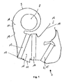
- Fig. 1 shows an automotive air conditioning system 7.
- an air conditioning housing 9 with a bottom wall 10 and an outlet opening 12, a fan 8, a filter 13, a refrigerant evaporator 14 and an electric heater 15 is arranged.
- the air conditioning housing 9 thus forms a channel 18 for passing the air.
- Walls 11 of the air conditioning housing 9 have on the inside a surface 19 which define the channel 18.
- the air for the interior of a motor vehicle is passed by means of the blower 8 through the filter 13, the refrigerant evaporator 14 and the electric heater 15.
- the motor vehicle air conditioning system 7 is thus not provided with a heat exchanger through which coolant flows for heating the air conducted through the motor vehicle system 7.
- the guided by the motor vehicle air conditioning 7 air is exclusively by means of the electric heater 15 heated.
- the motor vehicle air conditioning system 7 is preferably used in a motor vehicle with exclusively electric drive or with a hybrid drive (not shown). In order to achieve the necessary heating power by means of the electric heater 15, the electric heater 15 with high voltage, z. B. with more than 50 volts, operated.
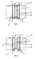
- FIGS. 2 and 3 is a first embodiment of the designed as a heat exchanger 6 electric heater 15 of the motor vehicle air conditioning 7 shown.
- the heat exchanger 6 comprises a plate-shaped PTC element 1 made of ceramic, a first printed circuit board 3 and a second printed circuit board 4 in each case as a conductor 20 in order to be able to conduct electrical current through the PTC element 1.
- Corrugated ribs 21 as heat-conducting elements 2 conduct the heat generated in the PTC element 1 due to the electrical resistance of the PTC element 1 to the air conducted by the motor vehicle air conditioning system 7.
- the heat-conducting elements 2 increase the surface area which is available to transfer heat to the air.
- the two printed circuit boards 3, 4 are glued to the PTC element 1.
- the heat-conducting elements 2 and the conductors 20 are made of metal, for. B. aluminum.
- the printed circuit boards 3, 4 have two narrow sides 16 and two broad sides 17 and are thus glued to the first width side 17 with the PTC element 1 and connected to the second broad side 17 with the corrugated fins 21 formed as heat conducting elements 2.
- the connection between the corrugated fins 21 and the printed circuit boards 3, 4 takes place indirectly with an insulating element 5.
- the insulating element 5 is formed as a coating 22 on the second broad side 17 of the printed circuit boards 3.4.
- the coating 22 is made of plastic and is applied by means of a coating process on the corresponding broad side 17 of the printed circuit boards 3, 4.
- As the coating method for example, an anodization method or eddy current sintering is used.
- the corrugated fins 21 are adhesively bonded to the insulating element 5 formed as a coating 22, ie materially connected.
- the corrugated fins 21 are adhesively bonded to the insulating element 5 formed as a coating 22, ie materially connected.
- also narrow sides 16 of the printed circuit boards 3, 4 are coated, so that the narrow sides 16 of the printed circuit boards 3, 4 are provided with the insulating 5 (not shown).
- the in Fig. 3 shown heat exchanger 6 thus has a layer structure, wherein the PTC element 1 is bonded to the two circuit boards 3, 4 and also the corrugated fins 21 are bonded to the insulating member 5 as a coating 22.
- a second embodiment of the heat exchanger 6 is shown.
- the insulating element 5 is made of plastic and is connected by means of encapsulation of the first and second printed circuit board 3, 4 with the first and second printed circuit board 3, 4.
- a circuit board 3, 4 is inserted into an injection mold and then introduced into the injection mold, preferably thermoplastic, plastic.
- the insulating element 5 made of plastic is thus directly connected to the first and second printed circuit board 3, 4.
- For better connection of the insulating element 5 on the first and second circuit board 3, 4 can be applied to the first or second circuit board 3, 4 adhesive before introducing the first and second circuit board 3, 4 in the injection mold.
- the insulating 5 covers a circuit board 3, 4 on the second broad side 17 completely and also completely both narrow sides 16 of the circuit board 3, 4 from.
- the first broad side 17 of the printed circuit board 3, 4 is partially covered by the insulating 5.
- This is a material and positive connection between the insulating 5 and the circuit boards 3, 4 before.
- the printed circuit boards 3, 4 are thus almost completely covered by the insulating element 5, so that a particularly good protection against electric shocks by the insulating element 5 is possible.
- the PTC element 1 with the two circuit boards 3, 4 and the corrugated fins 21 to the insulating member 5 materially connected by gluing.
- a third embodiment of the heat exchanger 6 is shown.
- the insulating element 5 is made of plastic. Ceramics or minerals, e.g. As MICA, or other material with a sufficiently good thermal conductivity to conduct the heat from the PTC element 1 to the corrugated fins 21 and on the other hand has a sufficiently good electrical insulation to the corrugated fins 21 from the high-voltage printed circuit board 3rd 4 electrically isolate and thereby to be able to prevent electrocution of a person when touching the corrugated fins 21.
- the insulating elements 5 cover the second broad side 17 and two narrow sides 16 of the printed circuit boards 3, 4 completely, so that the printed circuit boards 3, 4 are not covered by the insulating element 5 only in a small area of the first broad side 17.
- the remaining area of the first broad side 17 communicates with the PTC element 1, so that the remaining area does not have to be electrically insulated.
- the insulating element 5 is U-shaped in cross-section and is only placed on the circuit boards 3, 4 and materially connected by gluing.
- the PTC element 1 is also materially bonded by gluing to the two corresponding broad sides 17 of the printed circuit boards 3, 4.
- the corrugated fins 21 are materially connected by gluing with the two Isoller instituten 5.
- the heat exchanger 6 can also be operated with high voltage, without causing danger to persons from the high voltage.
- the corrugated fins 21 are electrically insulated from the conductors 20 by means of an insulating element 5. In a particularly advantageous manner not only the second broad side 17, but also both narrow sides 16 and partially also a part of the first broad side 17 of the circuit board 3, 4 covered by the insulating 5, so that the circuit boards 3, 4 are almost completely covered and thereby almost no risk of the Printed circuit boards 3, 4 can spend due to the high voltage applied there.
Landscapes
- Engineering & Computer Science (AREA)
- Physics & Mathematics (AREA)
- Thermal Sciences (AREA)
- Chemical & Material Sciences (AREA)
- Combustion & Propulsion (AREA)
- Mechanical Engineering (AREA)
- General Engineering & Computer Science (AREA)
- Air-Conditioning For Vehicles (AREA)
Priority Applications (1)
| Application Number | Priority Date | Filing Date | Title |
|---|---|---|---|
| EP08291087A EP2190257A1 (fr) | 2008-11-20 | 2008-11-20 | Caloporteur |
Applications Claiming Priority (1)
| Application Number | Priority Date | Filing Date | Title |
|---|---|---|---|
| EP08291087A EP2190257A1 (fr) | 2008-11-20 | 2008-11-20 | Caloporteur |
Publications (1)
| Publication Number | Publication Date |
|---|---|
| EP2190257A1 true EP2190257A1 (fr) | 2010-05-26 |
Family
ID=40436482
Family Applications (1)
| Application Number | Title | Priority Date | Filing Date |
|---|---|---|---|
| EP08291087A Withdrawn EP2190257A1 (fr) | 2008-11-20 | 2008-11-20 | Caloporteur |
Country Status (1)
| Country | Link |
|---|---|
| EP (1) | EP2190257A1 (fr) |
Cited By (2)
| Publication number | Priority date | Publication date | Assignee | Title |
|---|---|---|---|---|
| DE102017106711A1 (de) * | 2017-03-29 | 2018-10-04 | Dbk David + Baader Gmbh | Hochvolt-Luftheizer und Verfahren zu dessen Herstellung |
| EP4255110A1 (fr) * | 2022-03-30 | 2023-10-04 | Eberspächer catem GmbH & Co. KG | Dispositif de chauffage ptc et dispositif de chauffage électrique comprenant un tel dispositif de chauffage |
Citations (5)
| Publication number | Priority date | Publication date | Assignee | Title |
|---|---|---|---|---|
| US4327282A (en) | 1978-10-21 | 1982-04-27 | Firma Fritz Eichenauer | Electrical resistance heating element |
| US6178292B1 (en) * | 1997-02-06 | 2001-01-23 | Denso Corporation | Core unit of heat exchanger having electric heater |
| EP1768457A1 (fr) * | 2005-09-23 | 2007-03-28 | Catem GmbH & Co.KG | Element chauffant d'un dispositif de chauffage |
| EP1768458A1 (fr) | 2005-09-23 | 2007-03-28 | Catem GmbH & Co.KG | Elément chauffant d'un dispositif de chauffage |
| EP2023056A1 (fr) * | 2007-07-30 | 2009-02-11 | Chia-Hsiung Wu | Procédé de liaison pour un chauffage d'air et structure de celui-ci |
-
2008
- 2008-11-20 EP EP08291087A patent/EP2190257A1/fr not_active Withdrawn
Patent Citations (5)
| Publication number | Priority date | Publication date | Assignee | Title |
|---|---|---|---|---|
| US4327282A (en) | 1978-10-21 | 1982-04-27 | Firma Fritz Eichenauer | Electrical resistance heating element |
| US6178292B1 (en) * | 1997-02-06 | 2001-01-23 | Denso Corporation | Core unit of heat exchanger having electric heater |
| EP1768457A1 (fr) * | 2005-09-23 | 2007-03-28 | Catem GmbH & Co.KG | Element chauffant d'un dispositif de chauffage |
| EP1768458A1 (fr) | 2005-09-23 | 2007-03-28 | Catem GmbH & Co.KG | Elément chauffant d'un dispositif de chauffage |
| EP2023056A1 (fr) * | 2007-07-30 | 2009-02-11 | Chia-Hsiung Wu | Procédé de liaison pour un chauffage d'air et structure de celui-ci |
Cited By (2)
| Publication number | Priority date | Publication date | Assignee | Title |
|---|---|---|---|---|
| DE102017106711A1 (de) * | 2017-03-29 | 2018-10-04 | Dbk David + Baader Gmbh | Hochvolt-Luftheizer und Verfahren zu dessen Herstellung |
| EP4255110A1 (fr) * | 2022-03-30 | 2023-10-04 | Eberspächer catem GmbH & Co. KG | Dispositif de chauffage ptc et dispositif de chauffage électrique comprenant un tel dispositif de chauffage |
Similar Documents
| Publication | Publication Date | Title |
|---|---|---|
| EP2190256B1 (fr) | Caloporteur | |
| EP2724086B1 (fr) | Échangeur de chaleur | |
| EP2211590B1 (fr) | Echangeur de chaleur | |
| EP2428746B1 (fr) | Echangeur de chaleur | |
| EP2395295B1 (fr) | Echangeur de chaleur | |
| EP2428747B1 (fr) | Echangeur de chaleur | |
| US20160360572A1 (en) | PTC Heating Element and Electric Heating Device for an Automotive Vehicle Comprising Such a PTC Heating Element | |
| EP2397788A1 (fr) | Caloporteur et procédé de fabrication d'un tel caloporteur | |
| DE202011110647U1 (de) | Elektrische Fahrzeug-Heizvorrichtung | |
| EP2346304B1 (fr) | Caloporteur | |
| EP2395296B1 (fr) | Echangeur de chaleur | |
| EP2276321B1 (fr) | Caloporteur | |
| EP2190257A1 (fr) | Caloporteur | |
| EP2393336A1 (fr) | Caloporteur | |
| WO2009083107A1 (fr) | Dispositif de chauffage | |
| DE102011000116A1 (de) | Elektrische Fahrzeugheizvorrichtung | |
| EP2296432B1 (fr) | Caloporteur | |
| DE102020202195A1 (de) | Elektrische Heizeinrichtung | |
| EP2474793B1 (fr) | Échangeur de chaleur | |
| EP2293648A1 (fr) | Caloporteur | |
| EP3984799A1 (fr) | Réservoir de liquide doté d'une enveloppe en matière plastique | |
| EP2505396B1 (fr) | Climatisation de véhicule automobile | |
| WO2017050661A1 (fr) | Échangeur de chaleur et dispositif de chauffage de véhicule équipé d'un échangeur de chaleur | |
| EP1696181A1 (fr) | Radiateur avec un élément de chauffage électrique externe | |
| EP2506660A1 (fr) | Caloporteur |
Legal Events
| Date | Code | Title | Description |
|---|---|---|---|
| PUAI | Public reference made under article 153(3) epc to a published international application that has entered the european phase |
Free format text: ORIGINAL CODE: 0009012 |
|
| AK | Designated contracting states |
Kind code of ref document: A1 Designated state(s): AT BE BG CH CY CZ DE DK EE ES FI FR GB GR HR HU IE IS IT LI LT LU LV MC MT NL NO PL PT RO SE SI SK TR |
|
| AX | Request for extension of the european patent |
Extension state: AL BA MK RS |
|
| 17P | Request for examination filed |
Effective date: 20101126 |
|
| AKX | Designation fees paid |
Designated state(s): DE FR GB |
|
| 17Q | First examination report despatched |
Effective date: 20110119 |
|
| STAA | Information on the status of an ep patent application or granted ep patent |
Free format text: STATUS: THE APPLICATION IS DEEMED TO BE WITHDRAWN |
|
| 18D | Application deemed to be withdrawn |
Effective date: 20110730 |