EP2506660A1 - Caloporteur - Google Patents
Caloporteur Download PDFInfo
- Publication number
- EP2506660A1 EP2506660A1 EP11290159A EP11290159A EP2506660A1 EP 2506660 A1 EP2506660 A1 EP 2506660A1 EP 11290159 A EP11290159 A EP 11290159A EP 11290159 A EP11290159 A EP 11290159A EP 2506660 A1 EP2506660 A1 EP 2506660A1
- Authority
- EP
- European Patent Office
- Prior art keywords
- heat exchanger
- heating elements
- electrical resistance
- resistance heating
- conductor
- Prior art date
- Legal status (The legal status is an assumption and is not a legal conclusion. Google has not performed a legal analysis and makes no representation as to the accuracy of the status listed.)
- Granted
Links
Images
Classifications
-
- H—ELECTRICITY
- H05—ELECTRIC TECHNIQUES NOT OTHERWISE PROVIDED FOR
- H05B—ELECTRIC HEATING; ELECTRIC LIGHT SOURCES NOT OTHERWISE PROVIDED FOR; CIRCUIT ARRANGEMENTS FOR ELECTRIC LIGHT SOURCES, IN GENERAL
- H05B3/00—Ohmic-resistance heating
- H05B3/20—Heating elements having extended surface area substantially in a two-dimensional [2D] plane, e.g. plate-heater
- H05B3/22—Heating elements having extended surface area substantially in a two-dimensional [2D] plane, e.g. plate-heater non-flexible
- H05B3/24—Heating elements having extended surface area substantially in a two-dimensional [2D] plane, e.g. plate-heater non-flexible heating conductor being self-supporting
-
- B—PERFORMING OPERATIONS; TRANSPORTING
- B60—VEHICLES IN GENERAL
- B60H—ARRANGEMENTS OF HEATING, COOLING, VENTILATING OR OTHER AIR-TREATING DEVICES SPECIALLY ADAPTED FOR PASSENGER OR GOODS SPACES OF VEHICLES
- B60H1/00—Heating, cooling or ventilating devices
- B60H1/22—Heating, cooling or ventilating devices the heat source being other than the propulsion plant
- B60H1/2215—Heating, cooling or ventilating devices the heat source being other than the propulsion plant the heat being derived from electric heaters
- B60H1/2225—Heating, cooling or ventilating devices the heat source being other than the propulsion plant the heat being derived from electric heaters arrangements of electric heaters for heating air
-
- H—ELECTRICITY
- H05—ELECTRIC TECHNIQUES NOT OTHERWISE PROVIDED FOR
- H05B—ELECTRIC HEATING; ELECTRIC LIGHT SOURCES NOT OTHERWISE PROVIDED FOR; CIRCUIT ARRANGEMENTS FOR ELECTRIC LIGHT SOURCES, IN GENERAL
- H05B2203/00—Aspects relating to Ohmic resistive heating covered by group H05B3/00
- H05B2203/02—Heaters using heating elements having a positive temperature coefficient
-
- H—ELECTRICITY
- H05—ELECTRIC TECHNIQUES NOT OTHERWISE PROVIDED FOR
- H05B—ELECTRIC HEATING; ELECTRIC LIGHT SOURCES NOT OTHERWISE PROVIDED FOR; CIRCUIT ARRANGEMENTS FOR ELECTRIC LIGHT SOURCES, IN GENERAL
- H05B2203/00—Aspects relating to Ohmic resistive heating covered by group H05B3/00
- H05B2203/022—Heaters specially adapted for heating gaseous material
- H05B2203/023—Heaters of the type used for electrically heating the air blown in a vehicle compartment by the vehicle heating system
Definitions
- the invention relates to a heat exchanger according to the preamble of claim 1 and an automotive air conditioning system according to the preamble of claim 14.
- Automotive air conditioning systems serve to heat and / or to cool the air to be supplied to the interior of a motor vehicle.
- heat exchangers are used as electrical heaters to heat the air supplied to the interior.
- the electric heater includes PTC elements.
- Positive Temperature Coefficient (PTC) elements are current-carrying materials that have electrical resistance and can conduct electricity better at lower temperatures than at higher temperatures. Their electrical resistance thus increases with increasing temperature.
- the PTC element is generally made of ceramic and is a PTC thermistor. This raises regardless of the boundary conditions - such. B. applied voltage, nominal resistance or air flow to the PTC element - a very uniform surface temperature at the PTC element. Overheating can be prevented as it z. B. with a normal heat donating heating wire could occur, since regardless of the boundary conditions always about the same resistance and thus a substantially identical electric heating power is applied.
- the heat exchanger comprises PTC elements, at least two electrical conductors by means of which electrical current is conducted through the PTC element and heat conducting elements, in particular fins or corrugated fins, by means of which the surface for heating the air is increased.
- the conductors are designed as exclusively planar conductor plates and the PTC elements are positioned between two conductor plates as the conductor plate pair. A plurality of conductor plate pairs are stacked on top of each other and corrugated fins are secured between the conductor plate pairs. As a result, a large number of conductor sheets are disadvantageously required, which is associated with high costs in the production and a large weight.
- the US 4,327,282 shows a heat exchanger with a PTC heating element.
- Current is passed through the PTC heating element by means of contact plates and an insulating layer is arranged on the contact plates.
- the components are held together by means of a U-shaped clip.
- a heat generating element of a heater for air heating comprising at least one PTC element and voltage applied to opposite side surfaces of the PTC element electrical conductor tracks, wherein the two electrical conductors are surrounded on the outside by a non-electrically conductive insulating layer.
- the object of the present invention is therefore to provide a heat exchanger and an automotive air conditioning system, in which the corrugated fins and conductors can be made simple and inexpensive and the heat exchanger has a low weight.
- a heat exchanger comprising at least two electrical resistance heating elements, in particular at least two PTC elements, at least two conductors electrically connected to the at least two electrical resistance heating elements, in particular conductor plates, in order to conduct electrical current through the at least two electrical resistance heating elements and thereby to heat the electrical resistance heating elements, wherein at least two electrical resistance heating elements are arranged one above the other in a stacking direction and at least one conductor is arranged between the at least two electrical resistance heating elements in the stacking direction.
- the stacking direction is a direction in which the electrical resistance heating elements are stacked one above the other. Due to the arrangement of at least one conductor between two electrical resistance heating elements in the stacking direction, a plurality of electrical resistance heating elements with only two conductors can be arranged one above the other in a stacked arrangement and spaced apart.
- two conductors are arranged between each two electrical resistance heating elements in the stacking direction and / or the fictitious planes formed by the at least two electrical resistance heating elements, in particular at least two PTC elements, are substantially perpendicular to the stacking direction.
- each notional straight line which intersects at least two electrical resistance heating elements in particular cuts all electrical resistance heating elements, also cuts one, preferably two, conductors between two electrical resistance heating elements.
- the at least two conductors in particular conductor plates, have planar sections and bends and / or the at least two conductors are U-shaped, in particular multiply U-shaped.
- a conductor is formed several times in the direction of the stacking direction or the fictitious straight U-shaped and an opening at the U alternates alternately in the direction of the stacking direction or the notional straight line.
- the electrical resistance heating elements are at first planar portions on the electrical resistance heating elements and / or the bends are substantially 90 ° bends.
- 90 ° bends means that the bends are with a deviation of less than 30 °, 20 °, 10 ° or 5 ° bends of 90 °.
- the planar first sections are aligned substantially perpendicular to the stacking direction and / or fictitious straight line
- / or planar second sections of the conductors are aligned substantially parallel to the stacking direction and / or the notional straight line.
- the flat first section, d. H. a plane spanned by the planar first sections is oriented substantially perpendicular to the stacking direction and / or fictitious straight line, i. H. are aligned with a deviation of less than 30 °, 20 °, 10 ° or 5 ° perpendicular to the stacking direction and / or the imaginary plane.
- Aligned substantially parallel to the stacking direction means that the planar second portions of the conductors, i. H. the plane spanned by the planar second sections is aligned with a deviation of less than 30 °, 20 °, 10 ° or 5 ° parallel to the stacking direction and / or the notional straight line.
- a planar second section with two bends each is connected to two planar first sections or two planar first sections are connected with a curved portion of the conductor.
- Two flat first sections may also be provided with a curved section, e.g. B. a semicircle of the conductor in cross-section, be interconnected.
- corrugated ribs are formed on at least one conductor, in particular in one piece with the at least one conductor.
- the at least one conductor is provided with openings, in particular the openings are arranged in the region of the corrugated ribs, since the corrugated ribs are punched out of the at least one conductor.
- the corrugated ribs are punched out of the at least one conductor, in particular printed circuit boards and thereby formed integrally with the at least one conductor.
- the corrugated fins can be made particularly simple and inexpensive and it is also not separately produced connection between the corrugated fins and the at least one conductor required because when punching the corrugated fins from the at least one conductor, in particular conductor plate, a part of the conductor is only bent and characterized further a connection between the corrugated fins produced by forming and the rest of the conductor consists.
- the heat exchanger comprises only two conductors.
- the heat exchanger thus has only two conductors, so that with only two conductors, in particular conductor plates, electrical current is passed through a plurality of electrical resistance heating elements due to their geometry.
- it is advantageously not necessary to connect a multiplicity of electrical conductors to one another, and the production of the heat exchanger is therefore particularly simple and inexpensive.
- the at least two electrical resistance heating elements are connected to the at least two conductors in a materially bonded manner, in particular by gluing.
- the heat exchanger is provided with at least one electrical insulating element.
- the at least one electrical insulating element for.
- the acted upon by electrical current conductors can be electrically isolated from the environment.
- the heat exchanger comprises a frame for holding the at least two conductors with the at least two electrical resistance heating elements. With a frame, z. As plastic, the heat exchanger with the at least two electrical conductors and the at least two electrical resistance heating elements of objects, for. B. be attached to an air conditioning housing.
- the automotive air conditioning system comprises at least one heat exchanger according to one or more of the preceding claims.
- the motor vehicle air conditioning system expediently comprises an air filter and / or a blower and / or a refrigerant evaporator and / or an air conditioning housing, in particular made of plastic, and / or a duct for passing air through.
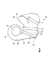
- Fig. 1 shows an automotive air conditioning system 14.
- an air conditioning housing 16 having a bottom wall 17 and an outlet portion 19, a fan 15, an air filter 20, a refrigerant evaporator 21 and a heat exchanger 1 is arranged as an electric heater.
- the air conditioning housing 16 thus forms a channel 22 for passing the air.
- Housing walls 18 of the air conditioning housing 16 have on the inside a surface 23 which define the channel 22.
- the air for the interior of a motor vehicle is passed by means of the blower 15 through the air filter 20, the refrigerant evaporator 11 and the heat exchanger 1.
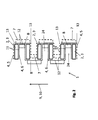
- the heat exchanger 1 comprises a multiplicity of electrical resistance heating elements 2 designed as PTC elements 3.
- the PTC elements 3 are arranged between a first conductor plate 5 and a second conductor plate 6 as conductor 4.
- the conductor sheets 5, 6 are made of metal, for. B. aluminum formed.
- the geometry of the first and second conductor plate 5, 6 is designed so that the stacked in a stacking direction 9 PTC elements 3 can be energized in only two sheets 5, 6 of these two sheets 5, 6 and between the PTC elements. 3 Gaps 24 are present.
- the intermediate spaces 24 are alternately bounded by the first conductor plate 5 and the second conductor plate 6.
- the stacking direction 9 and a notional straight line 10 are within the plane of Fig. 2 arranged.
- the fictitious line 10 provided that this parallel to the representation of Fig. 2 is moved, the PTC elements 3 intersects, in particular all electrical resistance heating elements 2, and also cuts two conductor plates 5, 6 between two PTC elements 3, ie alternately a first conductor plate 5 and a second conductor plate 6.
- the first and second conductor plates 5, 6 comprise first planar sections 11, which rest on the PTC elements 3 and second plane sections 12, which connect two first sections 11 together.
- the second planar sections 12 are aligned parallel to the stacking direction 9 and the first planar sections 11 are aligned perpendicular to the stacking direction 9. With a bend 13 of 90 °, the first and second planar sections 11, 12 are connected to each other ( Fig. 2 ).
- the first and second conductor plate 5, 6 is thus formed several times U-shaped.
- first corrugated fins 7 are punched out of the second planar portion 12 on the first conductor plate 5, and second corrugated fins 8 are punched out of the second conductor plate 6 on the second planar portion 12.
- the first and second corrugated fins 7, 8 increase the surface area for transferring heat from the first and second conductor plates 5, 6 and the first and second corrugated fins 7, 8, respectively, to the air circulated and conducted around the heat exchanger 1.
- the second planar portions 12 of both the first and the second conductor plate 5, 6 arise due to the punching of the corrugated fins 7, 8 from the second planar portions 12 in Fig. 2 not shown openings.
- the air can be directed perpendicular to the notional straight line through the intermediate spaces 24 and then through the openings, not shown, in the second planar sections 12.
- the first and second conductor plate 5, 6 and the PTC elements 3 are materially interconnected by means of adhesive.
- spacers are introduced into the interspaces and then a compressive force in the direction of the notional straight line 10 is applied to the top and bottom PTC element 3, so that the first two flat portions 11 on the PTC Elements 3 are pressed and thereby a good adhesive bond between the PTC elements 3 and the first planar portions 11 can be made.
- the spacers not shown, again removed from the spaces 24.
- the heat exchanger 1 comprises only two conductor plates 5, 6 with which by a plurality of PTC elements 3 electrical current can be passed. As a result, costs can be saved in the production, because only two conductor plates 5, 6 are required and a compact design of the heat exchanger 1 is possible in the arrangement, because the PTC elements 3 are arranged one above the other in the stacking direction 9.
Landscapes
- Physics & Mathematics (AREA)
- Thermal Sciences (AREA)
- Engineering & Computer Science (AREA)
- Mechanical Engineering (AREA)
- Air-Conditioning For Vehicles (AREA)
Priority Applications (1)
| Application Number | Priority Date | Filing Date | Title |
|---|---|---|---|
| EP11290159.0A EP2506660B1 (fr) | 2011-03-31 | 2011-03-31 | Caloporteur |
Applications Claiming Priority (1)
| Application Number | Priority Date | Filing Date | Title |
|---|---|---|---|
| EP11290159.0A EP2506660B1 (fr) | 2011-03-31 | 2011-03-31 | Caloporteur |
Publications (2)
| Publication Number | Publication Date |
|---|---|
| EP2506660A1 true EP2506660A1 (fr) | 2012-10-03 |
| EP2506660B1 EP2506660B1 (fr) | 2016-02-10 |
Family
ID=44343277
Family Applications (1)
| Application Number | Title | Priority Date | Filing Date |
|---|---|---|---|
| EP11290159.0A Not-in-force EP2506660B1 (fr) | 2011-03-31 | 2011-03-31 | Caloporteur |
Country Status (1)
| Country | Link |
|---|---|
| EP (1) | EP2506660B1 (fr) |
Cited By (1)
| Publication number | Priority date | Publication date | Assignee | Title |
|---|---|---|---|---|
| EP2793241A1 (fr) * | 2013-04-18 | 2014-10-22 | Behr France Rouffach SAS | Dispositif CTP |
Citations (7)
| Publication number | Priority date | Publication date | Assignee | Title |
|---|---|---|---|---|
| US4327282A (en) | 1978-10-21 | 1982-04-27 | Firma Fritz Eichenauer | Electrical resistance heating element |
| JPH01266015A (ja) * | 1988-04-15 | 1989-10-24 | Hitachi Ltd | 自動車用空気調和装置 |
| DE19539704A1 (de) * | 1994-10-25 | 1996-05-02 | Franz Steffan Dr Werner | Heizkörper |
| DE20016206U1 (de) * | 2000-09-15 | 2001-01-25 | Plastimat Oranienburg GmbH, 16515 Oranienburg | Elektrische Heizeinrichtung |
| US20040252986A1 (en) * | 2003-06-10 | 2004-12-16 | Hitoshi Ito | Electrical heater, heating heat exchanger and vehicle air conditioner |
| DE102006032772A1 (de) * | 2005-07-15 | 2007-01-25 | Modine Korea, LLC, Asan | PTC-Stabbaugruppe und Vorheizer der diese enthält |
| EP1768458A1 (fr) | 2005-09-23 | 2007-03-28 | Catem GmbH & Co.KG | Elément chauffant d'un dispositif de chauffage |
-
2011
- 2011-03-31 EP EP11290159.0A patent/EP2506660B1/fr not_active Not-in-force
Patent Citations (7)
| Publication number | Priority date | Publication date | Assignee | Title |
|---|---|---|---|---|
| US4327282A (en) | 1978-10-21 | 1982-04-27 | Firma Fritz Eichenauer | Electrical resistance heating element |
| JPH01266015A (ja) * | 1988-04-15 | 1989-10-24 | Hitachi Ltd | 自動車用空気調和装置 |
| DE19539704A1 (de) * | 1994-10-25 | 1996-05-02 | Franz Steffan Dr Werner | Heizkörper |
| DE20016206U1 (de) * | 2000-09-15 | 2001-01-25 | Plastimat Oranienburg GmbH, 16515 Oranienburg | Elektrische Heizeinrichtung |
| US20040252986A1 (en) * | 2003-06-10 | 2004-12-16 | Hitoshi Ito | Electrical heater, heating heat exchanger and vehicle air conditioner |
| DE102006032772A1 (de) * | 2005-07-15 | 2007-01-25 | Modine Korea, LLC, Asan | PTC-Stabbaugruppe und Vorheizer der diese enthält |
| EP1768458A1 (fr) | 2005-09-23 | 2007-03-28 | Catem GmbH & Co.KG | Elément chauffant d'un dispositif de chauffage |
Cited By (1)
| Publication number | Priority date | Publication date | Assignee | Title |
|---|---|---|---|---|
| EP2793241A1 (fr) * | 2013-04-18 | 2014-10-22 | Behr France Rouffach SAS | Dispositif CTP |
Also Published As
| Publication number | Publication date |
|---|---|
| EP2506660B1 (fr) | 2016-02-10 |
Similar Documents
| Publication | Publication Date | Title |
|---|---|---|
| EP2724086B1 (fr) | Échangeur de chaleur | |
| EP1318694B1 (fr) | Dispositif de chauffage électrique | |
| EP2428746B2 (fr) | Echangeur de chaleur | |
| EP2668450B1 (fr) | Échangeur à chaleur | |
| EP1061776B1 (fr) | Dispositif de chauffage destiné au réchauffement de l'air | |
| EP2395295B1 (fr) | Echangeur de chaleur | |
| EP2190256B1 (fr) | Caloporteur | |
| EP2428747B1 (fr) | Echangeur de chaleur | |
| DE102013105686B4 (de) | Fahrzeugheizung | |
| EP2346304B1 (fr) | Caloporteur | |
| EP1621378B2 (fr) | Dispositif de chauffage comprenant un élément chauffant, en particulier pour un véhicule | |
| DE10031541B4 (de) | Vorrichtung zum Vorheizen von Dieselkraftstoff | |
| EP2276321B1 (fr) | Caloporteur | |
| EP2395296B1 (fr) | Echangeur de chaleur | |
| EP2161514B1 (fr) | Echangeur de chaleur | |
| EP2506660B1 (fr) | Caloporteur | |
| EP2282605A1 (fr) | Dispositif de chauffage | |
| EP2505396B1 (fr) | Climatisation de véhicule automobile | |
| EP2296432B1 (fr) | Caloporteur | |
| EP2293648B1 (fr) | Caloporteur | |
| EP2474793B1 (fr) | Échangeur de chaleur | |
| EP2151639B1 (fr) | Caloporteur | |
| EP2083607A1 (fr) | Dispositif de chauffage en particulier d'un véhicule automobile | |
| DE102013226542B4 (de) | Heizvorrichtung | |
| EP2190257A1 (fr) | Caloporteur |
Legal Events
| Date | Code | Title | Description |
|---|---|---|---|
| PUAI | Public reference made under article 153(3) epc to a published international application that has entered the european phase |
Free format text: ORIGINAL CODE: 0009012 |
|
| AK | Designated contracting states |
Kind code of ref document: A1 Designated state(s): AL AT BE BG CH CY CZ DE DK EE ES FI FR GB GR HR HU IE IS IT LI LT LU LV MC MK MT NL NO PL PT RO RS SE SI SK SM TR |
|
| AX | Request for extension of the european patent |
Extension state: BA ME |
|
| 17P | Request for examination filed |
Effective date: 20130403 |
|
| RAP1 | Party data changed (applicant data changed or rights of an application transferred) |
Owner name: MAHLE BEHR FRANCE ROUFFACH S.A.S |
|
| GRAP | Despatch of communication of intention to grant a patent |
Free format text: ORIGINAL CODE: EPIDOSNIGR1 |
|
| INTG | Intention to grant announced |
Effective date: 20150828 |
|
| GRAS | Grant fee paid |
Free format text: ORIGINAL CODE: EPIDOSNIGR3 |
|
| GRAA | (expected) grant |
Free format text: ORIGINAL CODE: 0009210 |
|
| AK | Designated contracting states |
Kind code of ref document: B1 Designated state(s): AL AT BE BG CH CY CZ DE DK EE ES FI FR GB GR HR HU IE IS IT LI LT LU LV MC MK MT NL NO PL PT RO RS SE SI SK SM TR |
|
| REG | Reference to a national code |
Ref country code: GB Ref legal event code: FG4D Free format text: NOT ENGLISH |
|
| REG | Reference to a national code |
Ref country code: AT Ref legal event code: REF Ref document number: 775186 Country of ref document: AT Kind code of ref document: T Effective date: 20160215 Ref country code: CH Ref legal event code: EP |
|
| REG | Reference to a national code |
Ref country code: IE Ref legal event code: FG4D Free format text: LANGUAGE OF EP DOCUMENT: GERMAN |
|
| REG | Reference to a national code |
Ref country code: DE Ref legal event code: R096 Ref document number: 502011008845 Country of ref document: DE |
|
| REG | Reference to a national code |
Ref country code: FR Ref legal event code: PLFP Year of fee payment: 6 |
|
| REG | Reference to a national code |
Ref country code: LT Ref legal event code: MG4D |
|
| REG | Reference to a national code |
Ref country code: NL Ref legal event code: MP Effective date: 20160210 |
|
| PG25 | Lapsed in a contracting state [announced via postgrant information from national office to epo] |
Ref country code: ES Free format text: LAPSE BECAUSE OF FAILURE TO SUBMIT A TRANSLATION OF THE DESCRIPTION OR TO PAY THE FEE WITHIN THE PRESCRIBED TIME-LIMIT Effective date: 20160210 Ref country code: IT Free format text: LAPSE BECAUSE OF FAILURE TO SUBMIT A TRANSLATION OF THE DESCRIPTION OR TO PAY THE FEE WITHIN THE PRESCRIBED TIME-LIMIT Effective date: 20160210 Ref country code: NO Free format text: LAPSE BECAUSE OF FAILURE TO SUBMIT A TRANSLATION OF THE DESCRIPTION OR TO PAY THE FEE WITHIN THE PRESCRIBED TIME-LIMIT Effective date: 20160510 Ref country code: HR Free format text: LAPSE BECAUSE OF FAILURE TO SUBMIT A TRANSLATION OF THE DESCRIPTION OR TO PAY THE FEE WITHIN THE PRESCRIBED TIME-LIMIT Effective date: 20160210 Ref country code: FI Free format text: LAPSE BECAUSE OF FAILURE TO SUBMIT A TRANSLATION OF THE DESCRIPTION OR TO PAY THE FEE WITHIN THE PRESCRIBED TIME-LIMIT Effective date: 20160210 Ref country code: GR Free format text: LAPSE BECAUSE OF FAILURE TO SUBMIT A TRANSLATION OF THE DESCRIPTION OR TO PAY THE FEE WITHIN THE PRESCRIBED TIME-LIMIT Effective date: 20160511 |
|
| PG25 | Lapsed in a contracting state [announced via postgrant information from national office to epo] |
Ref country code: IS Free format text: LAPSE BECAUSE OF FAILURE TO SUBMIT A TRANSLATION OF THE DESCRIPTION OR TO PAY THE FEE WITHIN THE PRESCRIBED TIME-LIMIT Effective date: 20160610 Ref country code: RS Free format text: LAPSE BECAUSE OF FAILURE TO SUBMIT A TRANSLATION OF THE DESCRIPTION OR TO PAY THE FEE WITHIN THE PRESCRIBED TIME-LIMIT Effective date: 20160210 Ref country code: SE Free format text: LAPSE BECAUSE OF FAILURE TO SUBMIT A TRANSLATION OF THE DESCRIPTION OR TO PAY THE FEE WITHIN THE PRESCRIBED TIME-LIMIT Effective date: 20160210 Ref country code: BE Free format text: LAPSE BECAUSE OF NON-PAYMENT OF DUE FEES Effective date: 20160331 Ref country code: LV Free format text: LAPSE BECAUSE OF FAILURE TO SUBMIT A TRANSLATION OF THE DESCRIPTION OR TO PAY THE FEE WITHIN THE PRESCRIBED TIME-LIMIT Effective date: 20160210 Ref country code: NL Free format text: LAPSE BECAUSE OF FAILURE TO SUBMIT A TRANSLATION OF THE DESCRIPTION OR TO PAY THE FEE WITHIN THE PRESCRIBED TIME-LIMIT Effective date: 20160210 Ref country code: PT Free format text: LAPSE BECAUSE OF FAILURE TO SUBMIT A TRANSLATION OF THE DESCRIPTION OR TO PAY THE FEE WITHIN THE PRESCRIBED TIME-LIMIT Effective date: 20160613 Ref country code: LT Free format text: LAPSE BECAUSE OF FAILURE TO SUBMIT A TRANSLATION OF THE DESCRIPTION OR TO PAY THE FEE WITHIN THE PRESCRIBED TIME-LIMIT Effective date: 20160210 Ref country code: PL Free format text: LAPSE BECAUSE OF FAILURE TO SUBMIT A TRANSLATION OF THE DESCRIPTION OR TO PAY THE FEE WITHIN THE PRESCRIBED TIME-LIMIT Effective date: 20160210 |
|
| PG25 | Lapsed in a contracting state [announced via postgrant information from national office to epo] |
Ref country code: DK Free format text: LAPSE BECAUSE OF FAILURE TO SUBMIT A TRANSLATION OF THE DESCRIPTION OR TO PAY THE FEE WITHIN THE PRESCRIBED TIME-LIMIT Effective date: 20160210 Ref country code: EE Free format text: LAPSE BECAUSE OF FAILURE TO SUBMIT A TRANSLATION OF THE DESCRIPTION OR TO PAY THE FEE WITHIN THE PRESCRIBED TIME-LIMIT Effective date: 20160210 |
|
| REG | Reference to a national code |
Ref country code: CH Ref legal event code: PL |
|
| REG | Reference to a national code |
Ref country code: DE Ref legal event code: R097 Ref document number: 502011008845 Country of ref document: DE |
|
| PG25 | Lapsed in a contracting state [announced via postgrant information from national office to epo] |
Ref country code: SK Free format text: LAPSE BECAUSE OF FAILURE TO SUBMIT A TRANSLATION OF THE DESCRIPTION OR TO PAY THE FEE WITHIN THE PRESCRIBED TIME-LIMIT Effective date: 20160210 Ref country code: RO Free format text: LAPSE BECAUSE OF FAILURE TO SUBMIT A TRANSLATION OF THE DESCRIPTION OR TO PAY THE FEE WITHIN THE PRESCRIBED TIME-LIMIT Effective date: 20160210 Ref country code: CZ Free format text: LAPSE BECAUSE OF FAILURE TO SUBMIT A TRANSLATION OF THE DESCRIPTION OR TO PAY THE FEE WITHIN THE PRESCRIBED TIME-LIMIT Effective date: 20160210 Ref country code: SM Free format text: LAPSE BECAUSE OF FAILURE TO SUBMIT A TRANSLATION OF THE DESCRIPTION OR TO PAY THE FEE WITHIN THE PRESCRIBED TIME-LIMIT Effective date: 20160210 |
|
| PLBE | No opposition filed within time limit |
Free format text: ORIGINAL CODE: 0009261 |
|
| STAA | Information on the status of an ep patent application or granted ep patent |
Free format text: STATUS: NO OPPOSITION FILED WITHIN TIME LIMIT |
|
| REG | Reference to a national code |
Ref country code: IE Ref legal event code: MM4A |
|
| 26N | No opposition filed |
Effective date: 20161111 |
|
| GBPC | Gb: european patent ceased through non-payment of renewal fee |
Effective date: 20160510 |
|
| PG25 | Lapsed in a contracting state [announced via postgrant information from national office to epo] |
Ref country code: CH Free format text: LAPSE BECAUSE OF NON-PAYMENT OF DUE FEES Effective date: 20160331 Ref country code: IE Free format text: LAPSE BECAUSE OF NON-PAYMENT OF DUE FEES Effective date: 20160331 Ref country code: LI Free format text: LAPSE BECAUSE OF NON-PAYMENT OF DUE FEES Effective date: 20160331 |
|
| PG25 | Lapsed in a contracting state [announced via postgrant information from national office to epo] |
Ref country code: BG Free format text: LAPSE BECAUSE OF FAILURE TO SUBMIT A TRANSLATION OF THE DESCRIPTION OR TO PAY THE FEE WITHIN THE PRESCRIBED TIME-LIMIT Effective date: 20160510 Ref country code: SI Free format text: LAPSE BECAUSE OF FAILURE TO SUBMIT A TRANSLATION OF THE DESCRIPTION OR TO PAY THE FEE WITHIN THE PRESCRIBED TIME-LIMIT Effective date: 20160210 |
|
| REG | Reference to a national code |
Ref country code: FR Ref legal event code: PLFP Year of fee payment: 7 |
|
| REG | Reference to a national code |
Ref country code: AT Ref legal event code: MM01 Ref document number: 775186 Country of ref document: AT Kind code of ref document: T Effective date: 20160331 |
|
| PG25 | Lapsed in a contracting state [announced via postgrant information from national office to epo] |
Ref country code: GB Free format text: LAPSE BECAUSE OF NON-PAYMENT OF DUE FEES Effective date: 20160510 |
|
| PG25 | Lapsed in a contracting state [announced via postgrant information from national office to epo] |
Ref country code: MT Free format text: LAPSE BECAUSE OF FAILURE TO SUBMIT A TRANSLATION OF THE DESCRIPTION OR TO PAY THE FEE WITHIN THE PRESCRIBED TIME-LIMIT Effective date: 20160210 Ref country code: AT Free format text: LAPSE BECAUSE OF NON-PAYMENT OF DUE FEES Effective date: 20160331 |
|
| REG | Reference to a national code |
Ref country code: FR Ref legal event code: PLFP Year of fee payment: 8 |
|
| PG25 | Lapsed in a contracting state [announced via postgrant information from national office to epo] |
Ref country code: CY Free format text: LAPSE BECAUSE OF FAILURE TO SUBMIT A TRANSLATION OF THE DESCRIPTION OR TO PAY THE FEE WITHIN THE PRESCRIBED TIME-LIMIT Effective date: 20160210 Ref country code: HU Free format text: LAPSE BECAUSE OF FAILURE TO SUBMIT A TRANSLATION OF THE DESCRIPTION OR TO PAY THE FEE WITHIN THE PRESCRIBED TIME-LIMIT; INVALID AB INITIO Effective date: 20110331 |
|
| PG25 | Lapsed in a contracting state [announced via postgrant information from national office to epo] |
Ref country code: MC Free format text: LAPSE BECAUSE OF FAILURE TO SUBMIT A TRANSLATION OF THE DESCRIPTION OR TO PAY THE FEE WITHIN THE PRESCRIBED TIME-LIMIT Effective date: 20160210 Ref country code: LU Free format text: LAPSE BECAUSE OF NON-PAYMENT OF DUE FEES Effective date: 20160331 Ref country code: TR Free format text: LAPSE BECAUSE OF FAILURE TO SUBMIT A TRANSLATION OF THE DESCRIPTION OR TO PAY THE FEE WITHIN THE PRESCRIBED TIME-LIMIT Effective date: 20160210 Ref country code: MK Free format text: LAPSE BECAUSE OF FAILURE TO SUBMIT A TRANSLATION OF THE DESCRIPTION OR TO PAY THE FEE WITHIN THE PRESCRIBED TIME-LIMIT Effective date: 20160210 |
|
| PG25 | Lapsed in a contracting state [announced via postgrant information from national office to epo] |
Ref country code: AL Free format text: LAPSE BECAUSE OF FAILURE TO SUBMIT A TRANSLATION OF THE DESCRIPTION OR TO PAY THE FEE WITHIN THE PRESCRIBED TIME-LIMIT Effective date: 20160210 |
|
| PGFP | Annual fee paid to national office [announced via postgrant information from national office to epo] |
Ref country code: FR Payment date: 20190322 Year of fee payment: 9 |
|
| PGFP | Annual fee paid to national office [announced via postgrant information from national office to epo] |
Ref country code: DE Payment date: 20190404 Year of fee payment: 9 |
|
| REG | Reference to a national code |
Ref country code: DE Ref legal event code: R119 Ref document number: 502011008845 Country of ref document: DE |
|
| PG25 | Lapsed in a contracting state [announced via postgrant information from national office to epo] |
Ref country code: FR Free format text: LAPSE BECAUSE OF NON-PAYMENT OF DUE FEES Effective date: 20200331 Ref country code: DE Free format text: LAPSE BECAUSE OF NON-PAYMENT OF DUE FEES Effective date: 20201001 |