EP2190659B1 - Verbundmaterial und herstellungsverfahren dafür - Google Patents
Verbundmaterial und herstellungsverfahren dafür Download PDFInfo
- Publication number
- EP2190659B1 EP2190659B1 EP08788899A EP08788899A EP2190659B1 EP 2190659 B1 EP2190659 B1 EP 2190659B1 EP 08788899 A EP08788899 A EP 08788899A EP 08788899 A EP08788899 A EP 08788899A EP 2190659 B1 EP2190659 B1 EP 2190659B1
- Authority
- EP
- European Patent Office
- Prior art keywords
- resin
- outer layer
- impregnated
- inner layer
- layer
- Prior art date
- Legal status (The legal status is an assumption and is not a legal conclusion. Google has not performed a legal analysis and makes no representation as to the accuracy of the status listed.)
- Not-in-force
Links
- 238000000034 method Methods 0.000 title claims abstract description 32
- 239000002131 composite material Substances 0.000 title claims abstract description 22
- 238000004519 manufacturing process Methods 0.000 title claims abstract description 20
- 239000000463 material Substances 0.000 claims abstract description 109
- 229920005989 resin Polymers 0.000 claims abstract description 68
- 239000011347 resin Substances 0.000 claims abstract description 68
- 239000002657 fibrous material Substances 0.000 claims abstract description 36
- 229920006395 saturated elastomer Polymers 0.000 claims abstract description 24
- 239000011159 matrix material Substances 0.000 claims description 21
- 239000004745 nonwoven fabric Substances 0.000 claims description 11
- 238000013508 migration Methods 0.000 claims description 6
- 230000005012 migration Effects 0.000 claims description 6
- 230000006835 compression Effects 0.000 claims description 4
- 238000007906 compression Methods 0.000 claims description 4
- 238000007711 solidification Methods 0.000 claims description 4
- 230000008023 solidification Effects 0.000 claims description 4
- 239000003822 epoxy resin Substances 0.000 claims description 3
- 229920000647 polyepoxide Polymers 0.000 claims description 3
- 238000012360 testing method Methods 0.000 description 44
- 230000035515 penetration Effects 0.000 description 17
- 239000000835 fiber Substances 0.000 description 12
- 239000004744 fabric Substances 0.000 description 8
- 238000005470 impregnation Methods 0.000 description 8
- 238000006073 displacement reaction Methods 0.000 description 7
- 229920000728 polyester Polymers 0.000 description 7
- 238000009863 impact test Methods 0.000 description 6
- -1 polyethylene Polymers 0.000 description 6
- 239000011521 glass Substances 0.000 description 5
- 239000002184 metal Substances 0.000 description 4
- 238000007655 standard test method Methods 0.000 description 4
- 229920001187 thermosetting polymer Polymers 0.000 description 4
- 230000000750 progressive effect Effects 0.000 description 3
- 238000012345 traction test Methods 0.000 description 3
- 238000010521 absorption reaction Methods 0.000 description 2
- 238000013016 damping Methods 0.000 description 2
- 230000007423 decrease Effects 0.000 description 2
- 244000144992 flock Species 0.000 description 2
- 238000000465 moulding Methods 0.000 description 2
- 230000003287 optical effect Effects 0.000 description 2
- 230000001012 protector Effects 0.000 description 2
- 238000010998 test method Methods 0.000 description 2
- IQVNEKKDSLOHHK-FNCQTZNRSA-N (E,E)-hydramethylnon Chemical compound N1CC(C)(C)CNC1=NN=C(/C=C/C=1C=CC(=CC=1)C(F)(F)F)\C=C\C1=CC=C(C(F)(F)F)C=C1 IQVNEKKDSLOHHK-FNCQTZNRSA-N 0.000 description 1
- XQUPVDVFXZDTLT-UHFFFAOYSA-N 1-[4-[[4-(2,5-dioxopyrrol-1-yl)phenyl]methyl]phenyl]pyrrole-2,5-dione Chemical compound O=C1C=CC(=O)N1C(C=C1)=CC=C1CC1=CC=C(N2C(C=CC2=O)=O)C=C1 XQUPVDVFXZDTLT-UHFFFAOYSA-N 0.000 description 1
- 244000025254 Cannabis sativa Species 0.000 description 1
- 235000012766 Cannabis sativa ssp. sativa var. sativa Nutrition 0.000 description 1
- 235000012765 Cannabis sativa ssp. sativa var. spontanea Nutrition 0.000 description 1
- 229920000742 Cotton Polymers 0.000 description 1
- 239000004593 Epoxy Substances 0.000 description 1
- 229920000914 Metallic fiber Polymers 0.000 description 1
- 239000004698 Polyethylene Substances 0.000 description 1
- 239000004721 Polyphenylene oxide Substances 0.000 description 1
- 239000004743 Polypropylene Substances 0.000 description 1
- 239000004433 Thermoplastic polyurethane Substances 0.000 description 1
- NIXOWILDQLNWCW-UHFFFAOYSA-N acrylic acid group Chemical group C(C=C)(=O)O NIXOWILDQLNWCW-UHFFFAOYSA-N 0.000 description 1
- 239000000853 adhesive Substances 0.000 description 1
- 230000001070 adhesive effect Effects 0.000 description 1
- 239000010425 asbestos Substances 0.000 description 1
- 238000005452 bending Methods 0.000 description 1
- 235000009120 camo Nutrition 0.000 description 1
- 235000005607 chanvre indien Nutrition 0.000 description 1
- 239000003795 chemical substances by application Substances 0.000 description 1
- 230000001427 coherent effect Effects 0.000 description 1
- 229920001577 copolymer Polymers 0.000 description 1
- 239000004643 cyanate ester Substances 0.000 description 1
- 230000006378 damage Effects 0.000 description 1
- 238000009826 distribution Methods 0.000 description 1
- 239000006260 foam Substances 0.000 description 1
- 238000010438 heat treatment Methods 0.000 description 1
- 239000011487 hemp Substances 0.000 description 1
- 238000005259 measurement Methods 0.000 description 1
- 239000012528 membrane Substances 0.000 description 1
- 238000000879 optical micrograph Methods 0.000 description 1
- ISWSIDIOOBJBQZ-UHFFFAOYSA-N phenol group Chemical group C1(=CC=CC=C1)O ISWSIDIOOBJBQZ-UHFFFAOYSA-N 0.000 description 1
- 239000002985 plastic film Substances 0.000 description 1
- 229920006255 plastic film Polymers 0.000 description 1
- 229920003192 poly(bis maleimide) Polymers 0.000 description 1
- 229920002577 polybenzoxazole Polymers 0.000 description 1
- 229920000570 polyether Polymers 0.000 description 1
- 229920000573 polyethylene Polymers 0.000 description 1
- 229920001155 polypropylene Polymers 0.000 description 1
- 229920002635 polyurethane Polymers 0.000 description 1
- 239000004814 polyurethane Substances 0.000 description 1
- 238000002360 preparation method Methods 0.000 description 1
- 238000003825 pressing Methods 0.000 description 1
- 230000001902 propagating effect Effects 0.000 description 1
- 239000012925 reference material Substances 0.000 description 1
- 239000004627 regenerated cellulose Substances 0.000 description 1
- 239000011150 reinforced concrete Substances 0.000 description 1
- 229910052895 riebeckite Inorganic materials 0.000 description 1
- 238000009738 saturating Methods 0.000 description 1
- 239000004616 structural foam Substances 0.000 description 1
- 229920002994 synthetic fiber Polymers 0.000 description 1
- 229920002803 thermoplastic polyurethane Polymers 0.000 description 1
- 229920005992 thermoplastic resin Polymers 0.000 description 1
- 238000012546 transfer Methods 0.000 description 1
- 238000005303 weighing Methods 0.000 description 1
- 210000002268 wool Anatomy 0.000 description 1
Images


Classifications
-
- B—PERFORMING OPERATIONS; TRANSPORTING
- B62—LAND VEHICLES FOR TRAVELLING OTHERWISE THAN ON RAILS
- B62D—MOTOR VEHICLES; TRAILERS
- B62D25/00—Superstructure or monocoque structure sub-units; Parts or details thereof not otherwise provided for
- B62D25/08—Front or rear portions
- B62D25/16—Mud-guards or wings; Wheel cover panels
- B62D25/161—Mud-guards made of non-conventional material, e.g. rubber, plastics
-
- A—HUMAN NECESSITIES
- A42—HEADWEAR
- A42B—HATS; HEAD COVERINGS
- A42B3/00—Helmets; Helmet covers ; Other protective head coverings
- A42B3/04—Parts, details or accessories of helmets
- A42B3/06—Impact-absorbing shells, e.g. of crash helmets
-
- B—PERFORMING OPERATIONS; TRANSPORTING
- B29—WORKING OF PLASTICS; WORKING OF SUBSTANCES IN A PLASTIC STATE IN GENERAL
- B29C—SHAPING OR JOINING OF PLASTICS; SHAPING OF MATERIAL IN A PLASTIC STATE, NOT OTHERWISE PROVIDED FOR; AFTER-TREATMENT OF THE SHAPED PRODUCTS, e.g. REPAIRING
- B29C70/00—Shaping composites, i.e. plastics material comprising reinforcements, fillers or preformed parts, e.g. inserts
- B29C70/04—Shaping composites, i.e. plastics material comprising reinforcements, fillers or preformed parts, e.g. inserts comprising reinforcements only, e.g. self-reinforcing plastics
- B29C70/28—Shaping operations therefor
- B29C70/40—Shaping or impregnating by compression not applied
- B29C70/42—Shaping or impregnating by compression not applied for producing articles of definite length, i.e. discrete articles
- B29C70/46—Shaping or impregnating by compression not applied for producing articles of definite length, i.e. discrete articles using matched moulds, e.g. for deforming sheet moulding compounds [SMC] or prepregs
- B29C70/465—Shaping or impregnating by compression not applied for producing articles of definite length, i.e. discrete articles using matched moulds, e.g. for deforming sheet moulding compounds [SMC] or prepregs and impregnating by melting a solid material, e.g. sheets, powders of fibres
-
- B—PERFORMING OPERATIONS; TRANSPORTING
- B32—LAYERED PRODUCTS
- B32B—LAYERED PRODUCTS, i.e. PRODUCTS BUILT-UP OF STRATA OF FLAT OR NON-FLAT, e.g. CELLULAR OR HONEYCOMB, FORM
- B32B5/00—Layered products characterised by the non- homogeneity or physical structure, i.e. comprising a fibrous, filamentary, particulate or foam layer; Layered products characterised by having a layer differing constitutionally or physically in different parts
- B32B5/02—Layered products characterised by the non- homogeneity or physical structure, i.e. comprising a fibrous, filamentary, particulate or foam layer; Layered products characterised by having a layer differing constitutionally or physically in different parts characterised by structural features of a fibrous or filamentary layer
- B32B5/022—Non-woven fabric
-
- B—PERFORMING OPERATIONS; TRANSPORTING
- B32—LAYERED PRODUCTS
- B32B—LAYERED PRODUCTS, i.e. PRODUCTS BUILT-UP OF STRATA OF FLAT OR NON-FLAT, e.g. CELLULAR OR HONEYCOMB, FORM
- B32B5/00—Layered products characterised by the non- homogeneity or physical structure, i.e. comprising a fibrous, filamentary, particulate or foam layer; Layered products characterised by having a layer differing constitutionally or physically in different parts
- B32B5/02—Layered products characterised by the non- homogeneity or physical structure, i.e. comprising a fibrous, filamentary, particulate or foam layer; Layered products characterised by having a layer differing constitutionally or physically in different parts characterised by structural features of a fibrous or filamentary layer
- B32B5/024—Woven fabric
-
- B—PERFORMING OPERATIONS; TRANSPORTING
- B32—LAYERED PRODUCTS
- B32B—LAYERED PRODUCTS, i.e. PRODUCTS BUILT-UP OF STRATA OF FLAT OR NON-FLAT, e.g. CELLULAR OR HONEYCOMB, FORM
- B32B5/00—Layered products characterised by the non- homogeneity or physical structure, i.e. comprising a fibrous, filamentary, particulate or foam layer; Layered products characterised by having a layer differing constitutionally or physically in different parts
- B32B5/14—Layered products characterised by the non- homogeneity or physical structure, i.e. comprising a fibrous, filamentary, particulate or foam layer; Layered products characterised by having a layer differing constitutionally or physically in different parts characterised by a layer differing constitutionally or physically in different parts, e.g. denser near its faces
-
- B—PERFORMING OPERATIONS; TRANSPORTING
- B32—LAYERED PRODUCTS
- B32B—LAYERED PRODUCTS, i.e. PRODUCTS BUILT-UP OF STRATA OF FLAT OR NON-FLAT, e.g. CELLULAR OR HONEYCOMB, FORM
- B32B5/00—Layered products characterised by the non- homogeneity or physical structure, i.e. comprising a fibrous, filamentary, particulate or foam layer; Layered products characterised by having a layer differing constitutionally or physically in different parts
- B32B5/22—Layered products characterised by the non- homogeneity or physical structure, i.e. comprising a fibrous, filamentary, particulate or foam layer; Layered products characterised by having a layer differing constitutionally or physically in different parts characterised by the presence of two or more layers which are next to each other and are fibrous, filamentary, formed of particles or foamed
- B32B5/24—Layered products characterised by the non- homogeneity or physical structure, i.e. comprising a fibrous, filamentary, particulate or foam layer; Layered products characterised by having a layer differing constitutionally or physically in different parts characterised by the presence of two or more layers which are next to each other and are fibrous, filamentary, formed of particles or foamed one layer being a fibrous or filamentary layer
- B32B5/26—Layered products characterised by the non- homogeneity or physical structure, i.e. comprising a fibrous, filamentary, particulate or foam layer; Layered products characterised by having a layer differing constitutionally or physically in different parts characterised by the presence of two or more layers which are next to each other and are fibrous, filamentary, formed of particles or foamed one layer being a fibrous or filamentary layer another layer next to it also being fibrous or filamentary
-
- B—PERFORMING OPERATIONS; TRANSPORTING
- B32—LAYERED PRODUCTS
- B32B—LAYERED PRODUCTS, i.e. PRODUCTS BUILT-UP OF STRATA OF FLAT OR NON-FLAT, e.g. CELLULAR OR HONEYCOMB, FORM
- B32B2260/00—Layered product comprising an impregnated, embedded, or bonded layer wherein the layer comprises an impregnation, embedding, or binder material
- B32B2260/02—Composition of the impregnated, bonded or embedded layer
- B32B2260/021—Fibrous or filamentary layer
- B32B2260/023—Two or more layers
-
- B—PERFORMING OPERATIONS; TRANSPORTING
- B32—LAYERED PRODUCTS
- B32B—LAYERED PRODUCTS, i.e. PRODUCTS BUILT-UP OF STRATA OF FLAT OR NON-FLAT, e.g. CELLULAR OR HONEYCOMB, FORM
- B32B2260/00—Layered product comprising an impregnated, embedded, or bonded layer wherein the layer comprises an impregnation, embedding, or binder material
- B32B2260/04—Impregnation, embedding, or binder material
- B32B2260/046—Synthetic resin
-
- B—PERFORMING OPERATIONS; TRANSPORTING
- B32—LAYERED PRODUCTS
- B32B—LAYERED PRODUCTS, i.e. PRODUCTS BUILT-UP OF STRATA OF FLAT OR NON-FLAT, e.g. CELLULAR OR HONEYCOMB, FORM
- B32B2307/00—Properties of the layers or laminate
- B32B2307/50—Properties of the layers or laminate having particular mechanical properties
- B32B2307/51—Elastic
-
- B—PERFORMING OPERATIONS; TRANSPORTING
- B32—LAYERED PRODUCTS
- B32B—LAYERED PRODUCTS, i.e. PRODUCTS BUILT-UP OF STRATA OF FLAT OR NON-FLAT, e.g. CELLULAR OR HONEYCOMB, FORM
- B32B2307/00—Properties of the layers or laminate
- B32B2307/50—Properties of the layers or laminate having particular mechanical properties
- B32B2307/54—Yield strength; Tensile strength
-
- B—PERFORMING OPERATIONS; TRANSPORTING
- B32—LAYERED PRODUCTS
- B32B—LAYERED PRODUCTS, i.e. PRODUCTS BUILT-UP OF STRATA OF FLAT OR NON-FLAT, e.g. CELLULAR OR HONEYCOMB, FORM
- B32B2307/00—Properties of the layers or laminate
- B32B2307/50—Properties of the layers or laminate having particular mechanical properties
- B32B2307/546—Flexural strength; Flexion stiffness
-
- B—PERFORMING OPERATIONS; TRANSPORTING
- B32—LAYERED PRODUCTS
- B32B—LAYERED PRODUCTS, i.e. PRODUCTS BUILT-UP OF STRATA OF FLAT OR NON-FLAT, e.g. CELLULAR OR HONEYCOMB, FORM
- B32B2307/00—Properties of the layers or laminate
- B32B2307/50—Properties of the layers or laminate having particular mechanical properties
- B32B2307/582—Tearability
- B32B2307/5825—Tear resistant
Definitions
- the present invention relates to a composite material, a method for its production, a use of such material, a product and an article comprising said material.
- the present invention relates to a composite material having one first and one second outer layer and one inner layer, which comprises a first non-woven fibrous material and is positioned in contact between the first and the second layer; the first and the second outer layer are interconnected by means of at least one resin.
- the resin is usually distributed in a substantially uniform manner between the first and the second layer, saturating the inner layer.
- Said materials while featuring overall good mechanical characteristics, for some applications do not have sufficient resistance to peeling, resistance to penetration, absorption of impact energy and damping of mechanical and/or acoustic vibrations. Said materials also have a relatively high cost and weight (with equal thickness).
- the object of the present invention is to provide a composite material, a method for its production, a use of said material, a product and an article comprising said material which overcome, at least partly, the drawbacks of the known art and are, at the same time, easy and inexpensive to produce.
- the present invention accordingly provides a composite material, a method for its production, a use of said material, a product and an article comprising said material in accordance with the independent claims that follow and, preferably, with any one of the claims depending directly or indirectly on the independent claims.
- partially saturated fibrous material indicates a fibrous material comprising one or more substantially saturated or completely saturated areas.
- substantially saturated area indicates an area in which the fibres are inserted in a matrix defined by a resin.
- a group of fibres of a substantially saturated area have a flexibility which is markedly different from the flexibility of a group of fibres which are completely free of resin.
- the fibres of the substantially saturated area have a flexibility more similar to the flexibility of a group of fibres of a completely saturated area than the flexibility of a group of fibres free of resin.
- the substantially saturated areas can be completely saturated.
- completely saturated area indicates an area in which the fibres are inserted in a substantially continuous resin matrix.
- the fibres of a completely saturated area cannot move with respect to one another without breaking the resin matrix.
- substantially non-impregnated area indicates an area in which the fibres are completely devoid of resin or the fibres are impregnated with resin such that their flexibility is not remarkably different from the flexibility of the fibres completely devoid of resin; preferably, the flexibility of a group of fibres of the substantially non-impregnated area is more similar to the flexibility of a group of fibres free of resin than to the flexibility of a group of fibres of a completely saturated area.
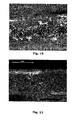
- the substantially saturated areas and the substantially non-impregnated areas can be distinguished under an optical microscope; the substantially non-impregnated areas remain porous and similar to a structural foam (see in particular figures 9-11 ).
- the dark areas with larger dimensions are the substantially non-impregnated areas.
- the areas featuring a plurality of white dots are the substantially saturated areas.
- needlepunched material indicates a fibrous material, preferably in ply form, which has undergone needlepunching.
- needlepunching indicates the treatment of a fibrous material in ply form; the treatment entails interlocking the fibres through the plane on which the ply lies and, preferably, in all directions.
- the needlepunching process usually involves pushing the fibres using needles.
- the fibres are distributed and positioned in the ply in a substantially random manner and so that at least part of the fibres cross the ply transversely from side to side.
- 1 indicates a product (partially illustrated in section) of the automotive industry, advantageously a car bodywork component (in particular a mudguard), made of composite material.
- the composite material has a first and a second outer layer 2 and 3 and an inner layer 4, which comprises a first non-woven fibrous material and is positioned in contact between the first and the second layer 2 and 3; the first and the second layer 2 and 3 are interconnected by means of at least one resin; the inner layer is partially saturated by the resin and has at least one area 5 substantially not impregnated by the resin.
- the inner layer 4 has a substantially non-impregnated volumetric fraction from 15% to 85%, advantageously from 20% to 85%, with respect to the total volume.
- the inner layer has a substantially non-impregnated volumetric fraction from 40% to 60%, advantageously from 45% to 55% with respect to the total volume.
- the inner layer has a substantially non-impregnated volumetric fraction from 60% to 85% with respect to its total volume; advantageously, from 65% to 85%; advantageously from 75% to 85%.
- the inner layer has a substantially non-impregnated volumetric fraction from 15% to 40% with respect to its total volume; advantageously from 20% to 30%.
- the distance between the first layer 2 and the substantially non-impregnated area 5 is less than three times the distance between the second layer 3 and the substantially non-impregnated area 5; the distance between the second layer 3 and the substantially non-impregnated area 5 is less than three times the distance between the first layer 2 and the substantially non-impregnated area 5.
- the inner layer 4 comprises an area 6 substantially saturated by the resin extending substantially uninterruptedly from the first to the second layer 2 and 3.
- the first fibrous material is substantially saturated by the resin at the level of the first and second layer 2 and 3.
- the inner layer 4 has a plurality of substantially non-impregnated areas 5.
- the inner layer 4 comprises (advantageously consists of) at least one material chosen from the group consisting of: synthetic organic fibres (for example polyethylene, polypropylene, polyamidic, polyester, polyimidic, polybenzoxazole, polyheteroaromatic), artificial fibres (for example based on regenerated cellulose), natural fibres (for example cotton, hemp, linen, wool, asbestos), metallic fibres.
- synthetic organic fibres for example polyethylene, polypropylene, polyamidic, polyester, polyimidic, polybenzoxazole, polyheteroaromatic
- artificial fibres for example based on regenerated cellulose
- natural fibres for example cotton, hemp, linen, wool, asbestos
- the non-woven fibrous material of the inner layer is a non-woven fabric.
- the inner layer consists of one single ply of fibrous material.
- the non-woven fibrous material of the inner layer is grouped so as to define a ply; the fibres are distributed and oriented in the ply so that at least part of the fibres cross the ply transversely, thus extending uninterruptedly from the first to the second layer 2 and 3.
- the cited non-woven fibrous material is a needlepunched material.
- the first and the second layer 2 and 3 comprise a material chosen from the group consisting of: "classic" braided fabric, a seamed multiaxial fabric, a unidirectional strip of fibres, a non-woven fibrous layer, a wide-mesh net or fibrous structure, a pure resinous film, a plastic film or membrane, a metal sheet.
- the first and the second layer 2 and 3 comprise, respectively, at least one second fibrous material and at least one third fibrous material.
- the second fibrous material is a braided material, in particular a woven material;
- the third fibrous material is a braided material, in particular a woven material.
- the first layer 2 comprises a first resinous matrix impregnating the second fibrous material; the second layer 3 comprises a second resinous matrix impregnating the third fibrous material.
- the first and/or second resinous matrix comprise said resin.
- the first layer 2 comprises a first resinous matrix impregnating the second fibrous material, while the second layer 3 contains no resinous element.
- At least one of the first and second layer 2 and 3 consists of the resin; for example, the first layer can consist of PVC.
- the first and the second layer 2 and 3 are substantially equal.
- the resin is chosen from a group consisting of: thermosetting resin (for example epoxy, polyester, polyurethane, acrylic, benzoxazinic, bismaleimide, cyanate ester, phenolic), thermoplastic resin (for example polyolefinic, halogenated polyolefinic, polyester, polyamidic, thermoplastic polyurethane; polyether, polyimidic and their copolymers) and an alternative type of adhesive.
- thermosetting resin for example epoxy, polyester, polyurethane, acrylic, benzoxazinic, bismaleimide, cyanate ester, phenolic
- thermoplastic resin for example polyolefinic, halogenated polyolefinic, polyester, polyamidic, thermoplastic polyurethane; polyether, polyimidic and their copolymers
- the resin is an expanding or non-expanding resin.
- the resin is based on syntactic foams.
- the resin is a thermosetting resin. According to some embodiments, it is an epoxy resin.
- a method for the production of a composite material as defined above.
- the method comprises a first overlay step, during which an inner layer 4, comprising a first substantially non-impregnated non-woven fibrous material, is overlaid in contact with a first outer layer 2; a second overlay step, in which a second outer layer 3 is overlaid in contact with the inner layer 4; a migration step, in which part of a resin migrates from at least one of the first and second layer 2 and 3 inside the inner layer 4 so that the inner layer 4 is partially saturated by the resin and has at least one area substantially not impregnated by the resin; a solidification step subsequent to the migration step and to the first and second overlay step and during which the resin is hardened.
- the method comprises a compression step, subsequent to the first and second overlay step, during which a pressure is exerted on a structure comprising the inner layer 4 positioned in contact between the first and the second layer 2 and 3.
- heat is supplied during the migration and/or solidification step.
- the method comprises a step of propagation of the vacuum subsequent to the first and second overlay step and prior to the compression step; during the vacuum propagation step, gas present inside the inner layer 4 is removed.
- the first layer 2 comprises a first resinous matrix and the second layer 3 comprises a second resinous matrix; said resin migrates from the first and from the second resinous matrix. According to further embodiments, said resin migrates from the first or from the second resinous matrix.
- the first and the second layer 2 and 3 comprise a fibrous material pre-impregnated with the first and the second resinous matrix respectively.
- the inner layer 4, the first and the second layer 2 and 3 are defined according to the above description for the product 1.
- a material which is defined as described above for the product 1, for the production of parts for the car and motorcycle industry.
- said material is provided for the production of components for car and motorcycle bodywork.
- a material defined as described above for the product 1, for the production of articles for personal protection, for example: helmets (e.g. for building sites and/or for sports use), back protectors for motorcyclists, hockey, cricket and/or American football shields.
- helmets e.g. for building sites and/or for sports use
- back protectors for motorcyclists, hockey, cricket and/or American football shields.
- T rc represents the resin thickness component present in the inner layer 4
- T c T t - 3.63 ⁇ 10 - 3 ⁇ FAW / D f in which T t indicates the total thickness of the material (mm), FAW indicates the grams per square metre of the fibres of the layers 2 and 3 (g/m 2 ), D f indicates the density of the fibres of the layers 2 and 3 (g/cm 3 ).
- the materials and products 1 obtained according to the present invention have resistance to peeling, absorption of impact energy, resistance to penetration and damping of relatively high mechanical and/or acoustic vibrations. Said materials furthermore have a relatively low cost and weight (with constant thickness).
- the mechanical characteristics of the materials produced according to the present invention make the materials themselves extremely useful for the production of car and motorcycle components, in particular bodywork components, and for the production of articles for personal protection, for example: helmets (for building sites or for sports use), back protectors for motorcyclists, hockey, cricket or American football shields.
- This example describes the production of a composite material in which the inner layer has a substantially non-impregnated volumetric fraction of approximately 79% with respect to its total volume.
- a panel measuring 30x30 cm was obtained by positioning a flock polyester fibre-based non-woven fabric, interlocked by means of needlepunching, Tessiltech PET//N SV type, 400 g/m 2 (manufactured by the company Edilfloor ® - Vicenza - IT) between two outer layers each consisting of a layer of 380 g/m 2 glass fabric, Twill 2x2 style, based on 300 tex E glass roving, impregnated with approximately 36.4% in weight (expressed as a percentage of the total weight inclusive of resin and fibre) of resin type DT806R (manufactured by Delta-Tech TM Sr1).
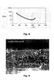
- the resin DT806R is a thermosetting epoxy resin with the following characteristics: curing temperature 65-140°C; gel time 50-60 minutes at 80°C, 15-19 minutes at 100°C, 4-6 minutes at 120°C, 2-3 minutes at 130°C; Tg after curing cycle 105-110°C after 600 minutes at 80°C, 115-125°C after 120 minutes at 100°C; viscosity curve shown in figure 8 .
- the Tessiltech PET//N SV type non-woven fabric is polyester fibre-based and has the following characteristics: weight per surface area 400 g/m2 (UNI EN 965); thickness 4.0 mm at 2kPa, 2.5 at 20kPa, 1.5 mm at 200kPa (UNI EN 964-1); longitudinal tensile strength 8.0 kN/m (UNI EN ISO 10319); longitudinal tensile elongation 110% (UNI EN ISO 10319); transverse tensile strength 11 kN/M (UNI EN ISO 10319); transverse tensile elongation 110% (UNI EN ISO 10319).
- the moulding was performed on a flat metal surface, with flat metal counter-plate, having the same plan dimensions as the panel to be moulded. Both the plate and counterplate had been treated with detaching agent, according to normal practice for this type of moulding.
- the first outer layer of impregnated fabric was deposited on the pressing plate, then a layer of the polyester non-woven fabric, the second layer of impregnated fabric and the metal counter-plate were deposited on top of it in the above sequence.
- the panel and the counter-plate were covered with a layer of non-woven fabric similar to the one described above, in this case with the sole function of propagating the vacuum onto the surface of the counter-plate and along the edges, after which everything was sealed with a vacuum bag provided with valve for the vacuum connection, according to normal practice for the manufacture of composite material components by means of autoclave.
- a vacuum bag provided with valve for the vacuum connection, according to normal practice for the manufacture of composite material components by means of autoclave.
- care was taken to ensure that the layer of non-woven fabric acting as vacuum propagator was in contact in some points with the non-woven fabric constituting the central part of the panel, so as to permit propagation of the vacuum inside it.
- the entire assembly thus constituted was placed inside an autoclave and the pressure outside the vacuum bag was brought to 4 bars. Once this pressure had been reached, the vacuum inside the bag was reduced until the supply pressure inside the bag was equal to the atmospheric pressure outside the autoclave. The temperature was then increased to 100°C at a speed of 2 ⁇ 3°C/min and kept at that temperature for 90 minutes. The temperature was then reduced to 60°C at a speed of approximately 5°C/min and the pressure of the autoclave was discharged to the outside. Lastly, the panel was taken out of the bag and separated from plate and counter-plate, at room temperature.
- This example describes the production of a composite material in which the inner layer has a substantially non-impregnated volumetric fraction of approximately 60% with respect to its total volume.
- the material is produced following the procedure of example 1 using a glass fabric impregnated with approximately 40.9% (instead of 36.4%) in weight (expressed as a percentage of the total weight inclusive of the resin and fibre) of resin type DT806R (manufactured by Delta-TechTM Srl).
- FIG. 10 A cross section of a panel thus obtained is shown in figure 10 .
- This example describes the production of a composite material in which the inner layer has a substantially non-impregnated volumetric fraction of approximately 20% with respect to its total volume.
- the material is produced following the procedure of example 1 using a glass fabric impregnated with approximately 49.4% (instead of 36.4%) in weight (expressed as a percentage of the total weight inclusive of resin and fibre) of resin type DT806R (manufactured by Delta-TechTM Srl).
- FIG. 11 A cross section of a panel thus obtained is shown in figure 11 .
- This example describes the production of a composite material in which the inner layer has a substantially saturated volumetric fraction.
- the material is produced by following the procedure of example 1 using a glass fabric impregnated with approximately 36.4% in weight (expressed as a percentage of the total weight inclusive of resin and fibre) of resin type DT806R (manufactured by Delta-TechTM Srl) and a flock polyester fibre-based non-woven fabric (Tessiltech PET//N SV type) completely impregnated with resin (60% in weight).
- This example describes traction tests performed on the materials obtained via the procedures described in examples 1 (material A), 2 (material B), 3 (material C) and 4 (material D).
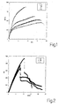
- the traction tests were performed according to the ASTM D3039 standard test method (ASTM is an acronym for American Society for Testing and Materials). This method provides for the testing of samples with dimensions of 25 mm width by 250 mm length. The traction speed is fixed at 5 mm/min and the test piece must be brought to breaking point. During the test the stress and deformation values are recorded. The tests were performed with configuration ⁇ 45 (i.e. not in the direction of the warp or weft but obliquely at approximately 45° with respect to the warp and weft).
- the parameters obtained from this test are: Young's modulus [MPa], tensile strength [MPa], extensibility [%].
- Figure 1 shows a comparison of the stress-deformation curves typical of the three materials; the X axis shows the percentage deformation and the Y axis shows the stress.
- the initial section with high elastic module is followed by a section in which a continuous increase in the stress is noted but with less stiffness.
- This characteristic is essentially due to the partial impregnation of the non-woven fabric, which determines a particular load transfer mechanism.
- the non-woven fabric in fact, can deform considerably without rupturing due to the presence of areas not impregnated with resin and which are therefore not subject to fractures at low levels of deformation.
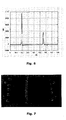
- This example describes flexion tests performed on the materials obtained by means of the procedures described in the examples 1-3.
- the ASTM D790 standard test method was used for the flexion tests. The choice of this method was dictated by specific considerations concerning the material. In fact, category C methods are appropriate for sandwich structures, but the reduced thickness (compared to the traditional type sandwich structures) of these test pieces makes the method unsuitable.
- the test method there must be a specific ratio between the span and the thickness of the test piece. More specifically, the method considers ratios from 16 to 40 acceptable, although in the case of continuous fibre composite materials a ratio of 32 or 40 is recommended. In this test, therefore, a ratio of 40 was used.
- Figure 2 shows the most representative load-travel comparison curves of the materials tested; the X axis shows the travel and the Y axis the load.
- the equipment used to perform the impact tests is the ball-drop impact tester.
- the impact is produced by a dart weighing 15.5 kg which falls from a known height, established by the operator, which can be up to 8 metres.
- ASTM D 5628-95 and ASTM F 736-81 standard test methods were referred to which indicate the best solution to be the use of removable supports provided with instruments, positioned on a bolted plate with log bolts embedded in a reinforced concrete base.
- test pieces used for the test are 20 cm x 40 cm. Four tests were performed for each type of lamina.
- This test measures the maximum load recorded, the impact energy necessary to cause breakage of the sample and the height at which the dart is positioned to record breakage of the sample.
- the breakage height is determined by carrying out preliminary tests on samples of material of non-standard size; the definitive height is confirmed by testing the first sample cut according to the standard test size.
- Table 3 Material Impact energy (J) Max load (N) Breaking height (m) A 388 7221 ⁇ 142 3.3 B 321 7623 ⁇ 150 2.8 C 321 9467 ⁇ 179 2.8 D ⁇ 229 19890 ⁇ 352 ⁇ 2
- Figure 7 shows a typical example of the fracture obtained with these types of materials. It can be seen that the fracture is fairly clean-cut without excessive signs of peeling.
- the results of the impact tests have shown that the materials A, B and C are surprisingly able to resist relatively high impact, dissipating considerable energy.
- the behaviour of material A which has a higher breaking height than that of materials B and C, was particularly surprising.
- material A showed greater dissipation of energy as shown by the lower maximum load value and that the dart bounces off the material C as shown by the double peak illustrated in figure 6 .
- the breaking height for the material D should be considered an upper limit; in fact, the current configuration of the instrument does not permit the recording of data with drops from a height of less than 2 metres. Therefore this height is certainly greater than the breaking point of the material; consequently also the impact energy is certainly greater than the maximum that can be absorbed by the material.
- materials A, B and C surprisingly have a considerably higher impact resistance and a markedly lower maximum force of impact (less than half) than material D.
- This example describes peeling tests performed on the materials obtained by means of the procedures described in examples 1-3.
- the peeling tests were performed with a 90° configuration using a fixing device of the type indicated in the ASTM D 6862 standard test method.
- the peeling tests were performed both on samples with fibres oriented at 0/90 and on samples with fibres oriented at ⁇ 45 with respect to the main axis of the test piece and, therefore, with respect to the peeling direction.
- test pieces are of fixed dimensions equal to 25 mm x 220 mm and the peeling speed is equal to 127 mm/min.
- the peeling force versus time is recorded.
- the important parameters are the maximum peak of force necessary to trigger the peeling and the resistance to peeling measured, understood as the mean force during the peeling step divided by the width of the test piece.
- the interesting datum obtained in this test is that the resistance to peeling is surprisingly higher than the resistance of the outer skin for all the samples tested. In fact, during the test, the outer skin broke instead of peeling.
- Table 4 shows the maximum force values measured and the considerations made above concerning the resistance to peeling.
- Table 4 Material Max Force [N] Resistance to peeling [N/mm] A (0/90) 60.85 ⁇ 0.63 > 2.43 - Breaking, no peeling A ( ⁇ 45) 72.26 ⁇ 5.13 > 2.89 - Breaking, no peeling B (0/90) 71.64 ⁇ 4.92 > 2.86 - Breaking, no peeling B ( ⁇ 45) 71.79 ⁇ 2.47 > 2.87 - Breaking, no peeling C (0/90) 67.16 ⁇ 5.48 > 2.01 - Breaking, no peeling C ( ⁇ 45) 70.33 ⁇ 2.35 > 2.81 - Breaking, no peeling
- the penetration test was performed by means of the standards and apparatus used for testing safety products that provide protection against piercing.
- the apparatus was appropriately modified to permit adequate gripping of the composite materials to be tested.
- Figure 13 schematically illustrates a portion of the measuring apparatus used in the test.
- the reference number 1 indicates a penetration tip and the reference number 2 indicates the sample.
- the penetration tip 1 had a hardness of 60 HRC and was provided with a truncated cone-shaped end.
- the penetration speed of the nail was 10 mm/min.
- the resistance to penetration value was obtained from the value in Newtons of the force corresponding to the first decrease in the force-displacement graph.
- the penetration resistance data shown in table 5 are obtained via a mean of at least five tests performed on different samples for each type of material analysed.
- Table 5 Material Resistance to penetration [N] Perforation displacement [mm] Resistance to penetration [N] A 325 ⁇ 20 1.75 ⁇ 0.16 325 ⁇ 20 B 340 ⁇ 81 1.55 ⁇ 0.18 340 ⁇ 81 C 494 ⁇ 28 1.51 ⁇ 0.08 494 ⁇ 28 D 477 ⁇ 111 2.30 ⁇ 0.44 477 ⁇ 111
- Figure 15 illustrates the penetration curves of the materials A, B, C and D.
- the Y axis shows the load and the X axis the displacement.
- the portion of substantially dry fibre in the inner layer confers greater strength which makes penetration of the conical portion of the tip more difficult, even after a first aperture has been made in the panel.
- the greater friction of the surface of the tip in contact with the portion of substantially non-impregnated fibres can also contribute to the greater resistance to penetration.
- the perforation proceeds more easily, once the laminate has undergone the first fracture due to the tip.
Landscapes
- Engineering & Computer Science (AREA)
- Textile Engineering (AREA)
- Chemical & Material Sciences (AREA)
- Mechanical Engineering (AREA)
- Composite Materials (AREA)
- Combustion & Propulsion (AREA)
- Transportation (AREA)
- Reinforced Plastic Materials (AREA)
- Laminated Bodies (AREA)
- Manufacture Of Alloys Or Alloy Compounds (AREA)
Claims (27)
- Verbundmaterial, das eine erste und eine zweite äußere Schicht (2, 3) und eine innere Schicht (4) aufweist, die ein erstes faseriges Vliesmaterial umfasst und die kontaktierend zwischen der ersten und der zweiten äußeren Schicht (2, 3) angeordnet ist, wobei die erste und die zweite äußere Schicht (2, 3) mit Hilfe mindestens eines Harzes verbunden sind, wobei die innere Schicht (4) teilweise mit diesem Harz gesättigt ist und mindestens einen Bereich (5) aufweist, der im Wesentlichen nicht mit dem Harz imprägniert ist, wobei die innere Schicht (4) einen im Wesentlichen nicht imprägnierten Volumenanteil von 15 % bis 85 %, bezogen auf sein Gesamtvolumen, aufweist, wobei die innere Schicht (4) einen Bereich (6) umfasst, der im Wesentlichen mit dem Harz gesättigt ist und sich im Wesentlichen ununterbrochen von der ersten bis zu der zweiten äußeren Schicht (2, 3) erstreckt.
- Material nach Anspruch 1, wobei die innere Schicht (4) einen im Wesentlichen nicht imprägnierten Volumenanteil von 20 % bis 80 %, bezogen auf ihr Gesamtvolumen, aufweist.
- Material nach Anspruch 2, wobei die innere Schicht (4) einen im Wesentlichen nicht imprägnierten Volumenanteil von 40 % bis 60 %, bezogen auf ihr Gesamtvolumen, aufweist.
- Material nach Anspruch 1 oder 2 oder 3, wobei der Abstand zwischen der ersten äußeren Schicht (2) und dem im Wesentlichen nicht imprägnierten Bereich (5) kleiner als dreimal der Abstand zwischen der zweiten äußeren Schicht (3) und dem im Wesentlichen nicht imprägnierten Bereich (5) ist, wobei der Abstand zwischen der zweiten äußeren Schicht (3) und dem im Wesentlichen nicht imprägnierten Bereich (5) kleiner als dreimal der Abstand zwischen der ersten äußeren Schicht (2) und dem im Wesentlichen nicht imprägnierten Bereich (5) ist.
- Material nach einem der vorhergehenden Ansprüche, wobei das erste faserige Material nahe bei der ersten und der zweiten äußeren Schicht (2, 3) im Wesentlichen mit dem Harz gesättigt ist.
- Material nach einem der vorhergehenden Ansprüche, wobei die innere Schicht eine Vielzahl von im Wesentlichen nicht imprägnierten Bereichen (5) aufweist.
- Material nach einem der vorhergehenden Ansprüche, wobei die innere Schicht (4) aus einer einzigen Lage aus einem faserigen Material, vor allem einem Vliesstoff, besteht.
- Material nach einem der vorhergehenden Ansprüche, wobei das erste faserige Vliesmaterial so angeordnet ist, dass es eine Lage definiert, wobei die Fasern so in der Lage verteilt und orientiert sind, dass mindestens ein Teil der Fasern die Lage quer durchziehen und sich dabei ohne ununterbrochen von der ersten bis zu der zweiten äußeren Schicht (2, 3) erstrecken.
- Material nach Anspruch 8, wobei das erste faserige Vliesmaterial ein Nadelfilzmaterial ist.
- Material nach einem der vorhergehenden Ansprüche, wobei die erste äußere Schicht (2) mindestens ein zweites faseriges Material und die zweite äußere Schicht (3) mindestens ein drittes faseriges Material umfasst.
- Material nach Anspruch 10, wobei das zweite faserige Material ein geflochtenes, vor allem gewebtes Material ist und wobei das dritte faserige Material ein geflochtenes, vor allem gewebtes Material ist.
- Material nach Anspruch 10 oder 11, wobei die erste äußere Schicht (2) eines erste Harzmatrix umfasst, die das zweite faserige Material imprägniert, und wobei die zweite äußere Schicht (3) eine zweite Harzmatrix umfasst, die das dritte faserige Material imprägniert.
- Material nach Anspruch 12, wobei die erste und/oder die zweite Harzmatrix das besagte Harz umfasst.
- Material nach einem der Ansprüche 1 bis 9, wobei die erste und/oder die zweite äußere Schicht (2, 3) aus dem Harz besteht.
- Material nach einem der vorhergehenden Ansprüche, wobei die erste und die zweite äußere Schicht (2, 3) im Wesentlichen gleich sind.
- Material nach einem der vorhergehenden Ansprüche, wobei das besagte Harz ein Epoxidharz umfasst.
- Verfahren zur Herstellung eines Verbundmaterials nach einem der vorhergehenden Ansprüche, das umfasst:einen ersten Überlagerungsschritt, in dem eine innere Schicht (4), die ein erstes im Wesentlichen nicht imprägniertes faseriges Vliesmaterial umfasst, kontaktierend auf eine erste äußere Schicht (2) aufgebracht wird;einen zweiten Überlagerungsschritt, in dem eine zweite äußere Schicht (3) kontaktierend auf die innere Schicht (4) aufgebracht wird;einen Wanderungsschritt, in dem ein Teil des Harzes von der ersten Schicht (2) und/oder der zweiten Schicht (3) in die innere Schicht (4) wandert, so dass die innere Schicht teilweise mit dem Harz gesättigt wird und mindestens einen Bereich (5) aufweist, der im Wesentlichen nicht mit dem Harz imprägniert ist;einen Verfestigungsschritt, der auf den Wanderungsschritt und den ersten Überlagerungsschritt und den zweiten Überlagerungsschritt folgt, in dessen Verlauf das Harz aushärtet.
- Verfahren nach Anspruch 17, das einen Verdichtungsschritt umfasst, der auf den ersten Überlagerungsschritt und den zweiten Überlagerungsschritt folgt, in dessen Verlauf ein Druck auf eine Struktur ausgeübt wird, die die innere Schicht (4) umfasst, die kontaktierend zwischen der ersten und der zweiten äußeren Schicht (2, 3) angeordnet ist.
- Verfahren nach Anspruch 17 oder 18, wobei im Laufe des Wanderungsschrittes und/oder des Verfestigungsschrittes Wärme zugeführt wird.
- Verfahren nach einem der Ansprüche 17 bis 19, das nach dem ersten Überlagerungsschritt und dem zweiten Überlagerungsschritt und vor dem Verfestigungsschritt einen Schritt umfasst, in dem ein Vakuum angelegt wird, wobei in dem Schritt, in dem das Vakuum angelegt wird, Gas entfernt wird, das in der inneren Schicht (4) enthalten ist.
- Verfahren nach einem der Ansprüche 17 bis 20, wobei die erste äußere Schicht (2, 3) eine erste Harzmatrix umfasst und die zweite äußere Schicht eine zweite Harzmatrix umfasst, wobei das Harz von der ersten und/oder der zweiten Harzmatrix wandert.
- Verfahren nach Anspruch 21, wobei das Harz von der ersten und von der zweiten Harzmatrix wandert.
- Verfahren nach Anspruch 21 oder 22, wobei die erste und die zweite äußere Schicht (2, 3) ein faseriges Material umfassen, das mit der ersten Harzmatrix bzw. der zweiten Harzmatrix vorimprägniert ist.
- Verwendung eines Materials nach einem der Ansprüche 1 bis 16 für die Herstellung von Teilen (1) für die Automobil- und die Motorradindustrie.
- Verwendung nach Anspruch 24 für die Herstellung von Automobil- und Motorradkomponenten.
- Produkt der Automobilindustrie, das ein Material nach einem der Ansprüche 1 bis 16 umfasst.
- Gegenstand für den persönlichen Schutz, der ein Material nach einem der Ansprüche 1 bis 16 umfasst.
Applications Claiming Priority (2)
| Application Number | Priority Date | Filing Date | Title |
|---|---|---|---|
| IT000506A ITBO20070506A1 (it) | 2007-07-20 | 2007-07-20 | Materiale composito e metodo per la sua realizzazione |
| PCT/IB2008/001883 WO2009013589A2 (en) | 2007-07-20 | 2008-07-18 | Composite material comprising voids, method for its production, use of the material and product comprising the material |
Publications (2)
| Publication Number | Publication Date |
|---|---|
| EP2190659A2 EP2190659A2 (de) | 2010-06-02 |
| EP2190659B1 true EP2190659B1 (de) | 2011-03-16 |
Family
ID=40225099
Family Applications (1)
| Application Number | Title | Priority Date | Filing Date |
|---|---|---|---|
| EP08788899A Not-in-force EP2190659B1 (de) | 2007-07-20 | 2008-07-18 | Verbundmaterial und herstellungsverfahren dafür |
Country Status (5)
| Country | Link |
|---|---|
| EP (1) | EP2190659B1 (de) |
| AT (1) | ATE501842T1 (de) |
| DE (1) | DE602008005615D1 (de) |
| IT (1) | ITBO20070506A1 (de) |
| WO (1) | WO2009013589A2 (de) |
Families Citing this family (2)
| Publication number | Priority date | Publication date | Assignee | Title |
|---|---|---|---|---|
| CN103201079B (zh) * | 2010-04-13 | 2015-09-09 | 汉高知识产权控股有限责任公司 | 可固化的组合物、利用该组合物制备复合材料的方法以及制备表面光洁度优异且纤维固结高的复合材料的方法 |
| JP5604590B2 (ja) * | 2011-05-25 | 2014-10-08 | 帝人株式会社 | 接合体 |
Family Cites Families (3)
| Publication number | Priority date | Publication date | Assignee | Title |
|---|---|---|---|---|
| CA2282387C (en) * | 1997-02-27 | 2007-10-02 | Advanced Composites Group Limited | Improvements in or relating to moulding methods and moulded articles |
| JP3737925B2 (ja) * | 2000-02-15 | 2006-01-25 | 株式会社アライヘルメット | ヘルメットにおける帽体の積層構造 |
| US20050266221A1 (en) * | 2004-05-28 | 2005-12-01 | Panolam Industries International, Inc. | Fiber-reinforced decorative laminate |
-
2007
- 2007-07-20 IT IT000506A patent/ITBO20070506A1/it unknown
-
2008
- 2008-07-18 EP EP08788899A patent/EP2190659B1/de not_active Not-in-force
- 2008-07-18 DE DE602008005615T patent/DE602008005615D1/de active Active
- 2008-07-18 AT AT08788899T patent/ATE501842T1/de not_active IP Right Cessation
- 2008-07-18 WO PCT/IB2008/001883 patent/WO2009013589A2/en not_active Ceased
Also Published As
| Publication number | Publication date |
|---|---|
| WO2009013589A2 (en) | 2009-01-29 |
| ATE501842T1 (de) | 2011-04-15 |
| ITBO20070506A1 (it) | 2009-01-21 |
| WO2009013589A8 (en) | 2010-04-15 |
| EP2190659A2 (de) | 2010-06-02 |
| DE602008005615D1 (de) | 2011-04-28 |
| WO2009013589A3 (en) | 2009-03-19 |
Similar Documents
| Publication | Publication Date | Title |
|---|---|---|
| JP5215841B2 (ja) | 熱可塑的変形繊維により強化された半製品の製造方法 | |
| US6536052B2 (en) | Safety helmets with cellular textile composite structure as energy absorber | |
| US4486372A (en) | Method for fabricating contoured perforated composite laminate structure | |
| JP5498389B2 (ja) | 耐衝撃性積層成形体およびその製造方法、ならびに耐衝撃材 | |
| EP3390035B1 (de) | Blechmaterial und stanzband damit | |
| US7347961B2 (en) | Method and system having a flowable pressure pad for consolidating an uncured laminate sheet in a cure process | |
| JP6145341B2 (ja) | 耐着氷・防音緩衝材及びその製造方法並びにそれを用いた車両用外装材 | |
| JP2012193466A (ja) | 不織布、この不織布の製造方法及びこの不織布を用いたサンドイッチ材 | |
| JP2007500615A (ja) | 引裂可能な弾性複合物品および製造方法 | |
| JPH01272636A (ja) | ガラス繊維マットで補強された熱可塑性半製品 | |
| EP2190659B1 (de) | Verbundmaterial und herstellungsverfahren dafür | |
| US20090162548A1 (en) | Method of manufacturing honeycomb and foam composite material | |
| JP2015189050A (ja) | 発泡シート積層体、繊維強化複合体、及び、発泡シート積層体の製造方法 | |
| AU2004260723B2 (en) | Device, especially sports device for surfing or similar and method for the production of fiber composite materials | |
| US20030132542A1 (en) | Fastener retention foam sheet and associated methods | |
| US20040195716A1 (en) | Method and system for utilizing low pressure for perforating and consolidating an uncured laminate sheet in one cycle of operation | |
| JPH10235665A (ja) | 板状体又は成形体及びその製法 | |
| US20040187661A1 (en) | Low penetration-force pinmat for perforating an uncured laminate sheet | |
| JP2019523814A (ja) | 複合部品または材料の機械加工または製造のためのフレキシブルコア | |
| JP7110017B2 (ja) | 補強用複合シート | |
| JPH06218859A (ja) | 積層体およびその製造方法 | |
| FI87549C (fi) | Traebaserad laminat | |
| EP0085642B1 (de) | Förderband und Verfahren zu seiner Herstellung | |
| US20070193490A1 (en) | Complex matting with a layer of volumized fibers | |
| JPH06155645A (ja) | 繊維複合体の製造方法 |
Legal Events
| Date | Code | Title | Description |
|---|---|---|---|
| PUAI | Public reference made under article 153(3) epc to a published international application that has entered the european phase |
Free format text: ORIGINAL CODE: 0009012 |
|
| 17P | Request for examination filed |
Effective date: 20100219 |
|
| AK | Designated contracting states |
Kind code of ref document: A2 Designated state(s): AT BE BG CH CY CZ DE DK EE ES FI FR GB GR HR HU IE IS IT LI LT LU LV MC MT NL NO PL PT RO SE SI SK TR |
|
| AX | Request for extension of the european patent |
Extension state: AL BA MK RS |
|
| GRAP | Despatch of communication of intention to grant a patent |
Free format text: ORIGINAL CODE: EPIDOSNIGR1 |
|
| DAX | Request for extension of the european patent (deleted) | ||
| GRAS | Grant fee paid |
Free format text: ORIGINAL CODE: EPIDOSNIGR3 |
|
| GRAA | (expected) grant |
Free format text: ORIGINAL CODE: 0009210 |
|
| AK | Designated contracting states |
Kind code of ref document: B1 Designated state(s): AT BE BG CH CY CZ DE DK EE ES FI FR GB GR HR HU IE IS IT LI LT LU LV MC MT NL NO PL PT RO SE SI SK TR |
|
| REG | Reference to a national code |
Ref country code: GB Ref legal event code: FG4D |
|
| REG | Reference to a national code |
Ref country code: CH Ref legal event code: EP |
|
| REG | Reference to a national code |
Ref country code: IE Ref legal event code: FG4D |
|
| REF | Corresponds to: |
Ref document number: 602008005615 Country of ref document: DE Date of ref document: 20110428 Kind code of ref document: P |
|
| REG | Reference to a national code |
Ref country code: DE Ref legal event code: R096 Ref document number: 602008005615 Country of ref document: DE Effective date: 20110428 |
|
| REG | Reference to a national code |
Ref country code: NL Ref legal event code: VDEP Effective date: 20110316 |
|
| PG25 | Lapsed in a contracting state [announced via postgrant information from national office to epo] |
Ref country code: ES Free format text: LAPSE BECAUSE OF FAILURE TO SUBMIT A TRANSLATION OF THE DESCRIPTION OR TO PAY THE FEE WITHIN THE PRESCRIBED TIME-LIMIT Effective date: 20110627 Ref country code: GR Free format text: LAPSE BECAUSE OF FAILURE TO SUBMIT A TRANSLATION OF THE DESCRIPTION OR TO PAY THE FEE WITHIN THE PRESCRIBED TIME-LIMIT Effective date: 20110617 Ref country code: LT Free format text: LAPSE BECAUSE OF FAILURE TO SUBMIT A TRANSLATION OF THE DESCRIPTION OR TO PAY THE FEE WITHIN THE PRESCRIBED TIME-LIMIT Effective date: 20110316 Ref country code: LV Free format text: LAPSE BECAUSE OF FAILURE TO SUBMIT A TRANSLATION OF THE DESCRIPTION OR TO PAY THE FEE WITHIN THE PRESCRIBED TIME-LIMIT Effective date: 20110316 Ref country code: HR Free format text: LAPSE BECAUSE OF FAILURE TO SUBMIT A TRANSLATION OF THE DESCRIPTION OR TO PAY THE FEE WITHIN THE PRESCRIBED TIME-LIMIT Effective date: 20110316 Ref country code: SE Free format text: LAPSE BECAUSE OF FAILURE TO SUBMIT A TRANSLATION OF THE DESCRIPTION OR TO PAY THE FEE WITHIN THE PRESCRIBED TIME-LIMIT Effective date: 20110316 Ref country code: NO Free format text: LAPSE BECAUSE OF FAILURE TO SUBMIT A TRANSLATION OF THE DESCRIPTION OR TO PAY THE FEE WITHIN THE PRESCRIBED TIME-LIMIT Effective date: 20110616 |
|
| LTIE | Lt: invalidation of european patent or patent extension |
Effective date: 20110316 |
|
| PG25 | Lapsed in a contracting state [announced via postgrant information from national office to epo] |
Ref country code: CY Free format text: LAPSE BECAUSE OF FAILURE TO SUBMIT A TRANSLATION OF THE DESCRIPTION OR TO PAY THE FEE WITHIN THE PRESCRIBED TIME-LIMIT Effective date: 20110316 Ref country code: FI Free format text: LAPSE BECAUSE OF FAILURE TO SUBMIT A TRANSLATION OF THE DESCRIPTION OR TO PAY THE FEE WITHIN THE PRESCRIBED TIME-LIMIT Effective date: 20110316 Ref country code: SI Free format text: LAPSE BECAUSE OF FAILURE TO SUBMIT A TRANSLATION OF THE DESCRIPTION OR TO PAY THE FEE WITHIN THE PRESCRIBED TIME-LIMIT Effective date: 20110316 Ref country code: BG Free format text: LAPSE BECAUSE OF FAILURE TO SUBMIT A TRANSLATION OF THE DESCRIPTION OR TO PAY THE FEE WITHIN THE PRESCRIBED TIME-LIMIT Effective date: 20110616 Ref country code: AT Free format text: LAPSE BECAUSE OF FAILURE TO SUBMIT A TRANSLATION OF THE DESCRIPTION OR TO PAY THE FEE WITHIN THE PRESCRIBED TIME-LIMIT Effective date: 20110316 |
|
| PG25 | Lapsed in a contracting state [announced via postgrant information from national office to epo] |
Ref country code: BE Free format text: LAPSE BECAUSE OF FAILURE TO SUBMIT A TRANSLATION OF THE DESCRIPTION OR TO PAY THE FEE WITHIN THE PRESCRIBED TIME-LIMIT Effective date: 20110316 |
|
| PG25 | Lapsed in a contracting state [announced via postgrant information from national office to epo] |
Ref country code: PT Free format text: LAPSE BECAUSE OF FAILURE TO SUBMIT A TRANSLATION OF THE DESCRIPTION OR TO PAY THE FEE WITHIN THE PRESCRIBED TIME-LIMIT Effective date: 20110718 Ref country code: EE Free format text: LAPSE BECAUSE OF FAILURE TO SUBMIT A TRANSLATION OF THE DESCRIPTION OR TO PAY THE FEE WITHIN THE PRESCRIBED TIME-LIMIT Effective date: 20110316 |
|
| PG25 | Lapsed in a contracting state [announced via postgrant information from national office to epo] |
Ref country code: SK Free format text: LAPSE BECAUSE OF FAILURE TO SUBMIT A TRANSLATION OF THE DESCRIPTION OR TO PAY THE FEE WITHIN THE PRESCRIBED TIME-LIMIT Effective date: 20110316 Ref country code: CZ Free format text: LAPSE BECAUSE OF FAILURE TO SUBMIT A TRANSLATION OF THE DESCRIPTION OR TO PAY THE FEE WITHIN THE PRESCRIBED TIME-LIMIT Effective date: 20110316 Ref country code: RO Free format text: LAPSE BECAUSE OF FAILURE TO SUBMIT A TRANSLATION OF THE DESCRIPTION OR TO PAY THE FEE WITHIN THE PRESCRIBED TIME-LIMIT Effective date: 20110316 Ref country code: IS Free format text: LAPSE BECAUSE OF FAILURE TO SUBMIT A TRANSLATION OF THE DESCRIPTION OR TO PAY THE FEE WITHIN THE PRESCRIBED TIME-LIMIT Effective date: 20110716 |
|
| PG25 | Lapsed in a contracting state [announced via postgrant information from national office to epo] |
Ref country code: MT Free format text: LAPSE BECAUSE OF FAILURE TO SUBMIT A TRANSLATION OF THE DESCRIPTION OR TO PAY THE FEE WITHIN THE PRESCRIBED TIME-LIMIT Effective date: 20110316 Ref country code: NL Free format text: LAPSE BECAUSE OF FAILURE TO SUBMIT A TRANSLATION OF THE DESCRIPTION OR TO PAY THE FEE WITHIN THE PRESCRIBED TIME-LIMIT Effective date: 20110316 |
|
| PLBE | No opposition filed within time limit |
Free format text: ORIGINAL CODE: 0009261 |
|
| STAA | Information on the status of an ep patent application or granted ep patent |
Free format text: STATUS: NO OPPOSITION FILED WITHIN TIME LIMIT |
|
| 26N | No opposition filed |
Effective date: 20111219 |
|
| PG25 | Lapsed in a contracting state [announced via postgrant information from national office to epo] |
Ref country code: DK Free format text: LAPSE BECAUSE OF FAILURE TO SUBMIT A TRANSLATION OF THE DESCRIPTION OR TO PAY THE FEE WITHIN THE PRESCRIBED TIME-LIMIT Effective date: 20110316 Ref country code: MC Free format text: LAPSE BECAUSE OF NON-PAYMENT OF DUE FEES Effective date: 20110731 Ref country code: PL Free format text: LAPSE BECAUSE OF FAILURE TO SUBMIT A TRANSLATION OF THE DESCRIPTION OR TO PAY THE FEE WITHIN THE PRESCRIBED TIME-LIMIT Effective date: 20110316 |
|
| REG | Reference to a national code |
Ref country code: DE Ref legal event code: R097 Ref document number: 602008005615 Country of ref document: DE Effective date: 20111219 |
|
| REG | Reference to a national code |
Ref country code: FR Ref legal event code: ST Effective date: 20120330 |
|
| REG | Reference to a national code |
Ref country code: IE Ref legal event code: MM4A |
|
| PG25 | Lapsed in a contracting state [announced via postgrant information from national office to epo] |
Ref country code: DE Free format text: LAPSE BECAUSE OF NON-PAYMENT OF DUE FEES Effective date: 20120201 Ref country code: FR Free format text: LAPSE BECAUSE OF NON-PAYMENT OF DUE FEES Effective date: 20110801 |
|
| REG | Reference to a national code |
Ref country code: DE Ref legal event code: R119 Ref document number: 602008005615 Country of ref document: DE Effective date: 20120201 |
|
| PG25 | Lapsed in a contracting state [announced via postgrant information from national office to epo] |
Ref country code: IT Free format text: LAPSE BECAUSE OF FAILURE TO SUBMIT A TRANSLATION OF THE DESCRIPTION OR TO PAY THE FEE WITHIN THE PRESCRIBED TIME-LIMIT Effective date: 20110316 |
|
| PG25 | Lapsed in a contracting state [announced via postgrant information from national office to epo] |
Ref country code: IE Free format text: LAPSE BECAUSE OF NON-PAYMENT OF DUE FEES Effective date: 20110718 |
|
| REG | Reference to a national code |
Ref country code: CH Ref legal event code: PL |
|
| GBPC | Gb: european patent ceased through non-payment of renewal fee |
Effective date: 20120718 |
|
| PG25 | Lapsed in a contracting state [announced via postgrant information from national office to epo] |
Ref country code: CH Free format text: LAPSE BECAUSE OF NON-PAYMENT OF DUE FEES Effective date: 20120731 Ref country code: LI Free format text: LAPSE BECAUSE OF NON-PAYMENT OF DUE FEES Effective date: 20120731 Ref country code: GB Free format text: LAPSE BECAUSE OF NON-PAYMENT OF DUE FEES Effective date: 20120718 |
|
| PG25 | Lapsed in a contracting state [announced via postgrant information from national office to epo] |
Ref country code: LU Free format text: LAPSE BECAUSE OF NON-PAYMENT OF DUE FEES Effective date: 20110718 |
|
| PG25 | Lapsed in a contracting state [announced via postgrant information from national office to epo] |
Ref country code: TR Free format text: LAPSE BECAUSE OF FAILURE TO SUBMIT A TRANSLATION OF THE DESCRIPTION OR TO PAY THE FEE WITHIN THE PRESCRIBED TIME-LIMIT Effective date: 20110316 |
|
| PG25 | Lapsed in a contracting state [announced via postgrant information from national office to epo] |
Ref country code: HU Free format text: LAPSE BECAUSE OF FAILURE TO SUBMIT A TRANSLATION OF THE DESCRIPTION OR TO PAY THE FEE WITHIN THE PRESCRIBED TIME-LIMIT Effective date: 20110316 |