EP2192020A1 - Dispositif de déplacement d'aiguilles, notamment des aiguilles à grande vitesse, et methode de déplacement d'aiguilles - Google Patents
Dispositif de déplacement d'aiguilles, notamment des aiguilles à grande vitesse, et methode de déplacement d'aiguilles Download PDFInfo
- Publication number
- EP2192020A1 EP2192020A1 EP08425763A EP08425763A EP2192020A1 EP 2192020 A1 EP2192020 A1 EP 2192020A1 EP 08425763 A EP08425763 A EP 08425763A EP 08425763 A EP08425763 A EP 08425763A EP 2192020 A1 EP2192020 A1 EP 2192020A1
- Authority
- EP
- European Patent Office
- Prior art keywords
- positive
- actuators
- extension
- unit
- points
- Prior art date
- Legal status (The legal status is an assumption and is not a legal conclusion. Google has not performed a legal analysis and makes no representation as to the accuracy of the status listed.)
- Granted
Links
Images


Classifications
-
- B—PERFORMING OPERATIONS; TRANSPORTING
- B61—RAILWAYS
- B61L—GUIDING RAILWAY TRAFFIC; ENSURING THE SAFETY OF RAILWAY TRAFFIC
- B61L5/00—Local operating mechanisms for points or track-mounted scotch-blocks; Visible or audible signals; Local operating mechanisms for visible or audible signals
- B61L5/04—Fluid-pressure devices for operating points or scotch-blocks
- B61L5/045—Fluid-pressure devices for operating points or scotch-blocks using electrically controlled fluid-pressure operated driving means
Definitions
- the present invention relates to a device for moving railroad switch points, particularly high-speed ones of the type comprising:
- each switch has a plurality of actuators arranged along the longitudinal direction of points and are provided only at the region of diverging ends of points and at the region of converging ends of points, so called switch frog, or they are provided in a greater number, i.e. they are arranged closer one to the other in such regions.
- each actuator has to perform a stroke corresponding to the movement of points in the actuator position with reference to the longitudinal direction of points. Such stroke is different for each actuator having a different position along the longitudinal direction of points. Moreover during the movement actuators have to move in a synchronized way in order to prevent transverse deformations of points.
- Hydraulic linear actuators and particularly oil-hydraulic actuators are currently used, which actuators are supplied by a pressure fluid supply unit. Individual actuators are connected in parallel to the delivery of the supply unit and fluid is distributed to individual actuators merely on the basis of the greater or lower resistance actuators are subjected to when performing the movement stroke. During the movement this leads to the fact that points can be subjected to transverse deformations which can attain such a level that points take a wave-like configuration in the transversal direction at intermediate positions of the stroke thereof.
- the stroke is determined by the fact that at the point toe there is a mechanical limit abutment against the track rail, while at intermediate positions of the length of points the limit position is determined by the resistance to transverse deformation made by the material of the point to corresponding actuators when the toe is in the limit position, whether in the final position the point shows a weakening of the resistance to the transverse deformation, the shape of the point, i.e. its curvature in the final limit condition will not be the desired one and it will change depending on different resistance characteristics the material of the point can show in the different regions of its length.
- the invention is based on the drawback of allowing points to be moved such that transverse stresses or deformations of points are prevented above all at intermediate positions for the transition between the two positions abutting against one of the two tracks making the rail, all by means which are simple, inexpensive, not so much subjected to breaking, damages and requiring not so much maintenance and moreover means that can be easily controlled and in such a way to allow operation to be easily controlled according to safety standards of the railway field.
- a further aim of the invention is to allow existing devices for moving points in existing switches to be modified or also to allow the synchronization device of actuators to be inserted later, without the need of important changes to the switch, the control unit and hydraulic circuit supplying actuators.
- the invention achieves the above aims by providing a device of the type described hereinbefore, and comprising also:
- each adjustment unit is composed of a positive-displacement pump, said positive-displacement pumps being driven at the same driving speed while having predetermined and steady displacements.
- Advantageously displacements of pumps are defined during the design phase and are defined on the basis of the predetermined amount of fluid per unit of time for achieving the synchronized motion of individual actuators one with respect to the other.
- each actuator determines the amount of fluid necessary to the actuator for the passage of the two initial and limit positions under normal driving conditions, i.e. when a predetermined translation resistance of the point is provided where the actuator is provided.
- positive-displacement pump denotes a pump providing a suction/compression chamber having a predetermined volume and changing the fluid delivery depending on the driving speed of a suction/compression member.
- a particular positive-displacement pump is the piston pump or gear pump.
- volume of the pressure fluid that can be supplied per unit of time is determined by the displacement and by the number of suction/compression strokes of the piston.
- pumps that can be considered as positive-displacement pumps according to the definition used in the present invention such as rotary pumps and/or pumps with suction/compression members made according to the principle of the Wankel engine and wherein the suction/compression chamber has a steady and predetermined volume.
- the same speed driving individual positive-displacement pumps can be obtained by several means such as for example by using a separate motor for driving each pump and by driving said motors in a synchronized way.
- a separate motor for driving each pump and by driving said motors in a synchronized way.
- an encoder detecting the number of revolutions per unit of time of individual motors and providing the data to a unit driving individual motors which adjustes the supply thereof such that motors can drive positive-displacement pumps at the same speed.
- the invention provides the common transmission supplying the driving motion of the common motor to individual positive-displacement pumps to be composed of a single drive shaft that is connected to or is the input shaft of each positive-displacement pump and which drive shaft is rotated by the single driving motor.
- the invention provides a device for moving railroad switch points particularly high-speed ones, comprising:
- the displacement is defined in the design phase and it is steady, but even the speed in driving pumps can be easily determined with a single motor and with such a transmission that any likelihood of losing the synchronization is prevented.
- the device requires only that in the case of a control actuating the switch in addition to drive the control unit also the motor driving pumps has to be driven.
- control unit may not require means for generating and storing a pressure fluid but may require only a simple fluid reservoir.
- driving controls can be related to a single motor and so they can be simple, not expensive and effective.
- the device is very strong and it is not so much subjected to damages and it provides the possibility of being made such that it is possible to have a rapid replacement above all of individual positive-displacement pumps.
- the shaft can be operatively connected to the input shaft of each pump by a pair of gears allowing the drive shaft to be arranged parallely to other input shafts of individual pumps such that pumps can be put side by side laterally of the shaft.
- the invention provides synchronization means to be composed of a separate and independent constructional member comprising:
- the constructional member can comprise a common case for all positive-displacement pumps, which case has:
- said synchronization means are provided with a modular structure.
- synchronization means can be mounted later into an existing circuit supplying actuators, it is not necessary for said synchronization means to be specially made ad hoc for the specific plant where they will be mounted.
- An embodiment provides a main frame or support structure to have such a size to house at least two positive-displacement pumps, which structure or frame is provided with structure or frame extensions that can be removably mounted.
- Extensions can be composed of frame members provided with means for being fastened to the main frame portion and in turn they can be provided with means for being fastened to a further extension, while each frame extension member has such a size to house at least a further positive-displacement pump or a predetermined number of additional positive-displacement pumps and an extension for transmitting the drive motion to individual additional positive-displacement pumps housed in said frame extension member.
- Said transmission extension for example a common drive shaft has means for being operatively removably connected to the transmission, for example to the common drive shaft of positive-displacement pumps on the main member.
- Advantageously positive-displacement pumps can be arranged adjacent one with the other on a row laterally offset with respect to the common transmission shaft, both within the main member and in extension members said extension being provided at a side of the main support or frame member provided at the end of the drive shaft opposite to the end of the driving motor.
- Transmission extensions can be composed for example of projections of the common drive shaft provided with an end for being connected to the end of said drive shaft.
- actuating cylinders are of the double-acting type having two supply inlets and each of said supply inlets being connectable alternatively to the delivery of the control unit and synchronization means being provided between the delivery of the control pump and each one of the two inlets of each double-acting actuating cylinder.
- Said synchronization means provided at the two inlets of double-acting actuating cylinders are made according to one or more of the combinations or subcombinations of the characteristics listed above for synchronization means in combination with simple actuating cylinders.
- the invention relates also to a method for moving railroad switch points by means of hydraulic actuators wherein points are moved by at least two hydraulic actuators which are supplied by a common supply unit.
- the amount of supplied fluid for each actuator is adjusted in a way corresponding to the synchronized movement over time of two or more actuators.
- such adjustment is obtained by using positive-displacement pumps driven at the same drive speed and for an equal and coincident drive time period, while the delivery volume of each pump is determined in proportion to the amount of pressure fluid required by the corresponding actuator to be moved in a synchronized way with other actuators from an initial position to a limit position.
- Said method is based on the concept of providing for each actuator supply means having such a size to provide per unit of time an amount of fluid measured on the basis of the fluid necessary for performing the stroke of said actuator in a synchronized way with other actuators and said supply means being driven for the same and coincident drive period.
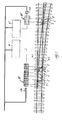
- FIG. 1 schematically shows a railroad switch, particularly of the high-speed type.
- the switch comprises two points denoted by A1 and A2 and a frog denoted by C.
- A1 and A2 At the region of diverging ends of points A1, A2 i.e. at the region opposite to the frog C movement linear actuators denoted by 1 and 2 are provided, each one being mounted at one of the sleepers T and whose rod is fastened to points at a different location along the longitudinal direction thereof.
- linear actuators 3, 3' are provided also in the region of the switch frog C.
- Advantageously linear actuators are of the hydraulic type and here they are of the double-acting type, since points have to be moved from a position with the point A1 abutting against the rail laterally adjacent thereto to a position wherein the point A2 abuts against the rail laterally adjacent thereto and again to the position wherein the point A1 abuts against the adjacent rail.
- Actuating cylinders 1, 2, 3 and 3' are supplied with a pressure fluid, particularly oil from a supply unit of said pressure fluid which is denoted by 4. It can supply all actuators or it is possible to provide a separate unit 4' supplying only actuators of the frog C with the unit 4 supplying remaining actuators.
- the unit 4, 4' supplying fluid for driving linear actuators does not directly supply said fluid to actuators, but it provides the fluid to synchronization means 10 provided between the delivery side of the unit 4, 4' and each inlet of each actuating cylinder 1, 2, 3, 3'.
- Synchronization means are made such that each hydraulic cylinder is provided with an amount of pressure fluid per unit of time related to the stroke the rod of the actuating cylinder 1, 2, 3, 3' has to made in order to move the transverse section of points A1, A2 where said actuator is provided in the correct position with reference to the two limit positions of points described above. It has to be noted that the movement stroke of points A1, A2 is different depending on the position of the actuator with reference to the longitudinal extension of points, it is greater in the end region wherein the actuator 1 is provided and it becomes more and more small towards the frog C.
- synchronization means 10 to be composed of single synchronization units 110, in the form of so called positive-displacement pumps and are contemporaneously driven and for the same time period by a common motor 210 whose motion is transmitted to individual positive-displacement pumps 110 by a common transmission.
- the shown embodiment provides synchronization means 10', in a not limitative way but merely as a possibility, also for actuators 3, 3' of the switch frog C which are made like means 10, therefore the detailed description thereof is omitted since the detailed description regarding synchronization means 10 for actuators 1 and 2 can be applied also to said synchronization means 10' for actuators 3, 3' of the switch frog C.
- each synchronization unit 110 i.e. each positive-displacement pump to be driven by a separate motor there being provided a method for synchronizing speeds and time for energizing individual motors, for example by means of an encoder and a power supply unit therefor
- the embodiment providing only one motor 210 is advantageous, since it is surely more accurate in keeping the synchronization in driving synchronization units 110 and it is less subjected to losses caused by adverse combination of tolerances.
- only one actuating control has to be sent only to the motor and to the unit, therefore both the transmission of controls for actuating the switch and the functional control of the switch as well as the diagnostic control on different actuating members intended for moving points are semplified.
- FIG. 2 shows in details a circuit diagram of the device according to the present invention and according to the preferred embodiment wherein synchronization units 110 are composed of a positive-displacement pump 110.
- individual double-acting actuators are denoted by 1 and 2 and synchronization means are denoted by 10 two of them being provided since a synchronization unit 10 is provided for each one of the two inlets of the double-acting cylinders 1, 2.
- Synchronization means are composed of a positive-displacement pump 110 for each linear actuator 1, 2. All positive-displacement pumps are supplied by a common inlet line 310 which is connected to the delivery of the unit 4, while the outlet of each positive-displacement pump 110 is connected to one of the inlets of an associated actuating cylinder 1, 2.
- each one of the two inlets of a double-acting actuating cylinder is connected to the delivery of a positive-displacement pump 110 being part of synchronization means 10 of actuators for the movement stroke of points in one of the two different movement directions, while deliveries of the two positive-displacement pumps 110 connected to one of the two inlets of a double-acting actuating cylinder 1, 2 respectively are connected together by a balance line provided with a check valve and generally denoted by 11 and while an on-off valve 12 is provided on each connection lines between the delivery of each positive-displacement pump and the corresponding inlet of the corresponding actuator 1, 2.
- FIGS. 2 and 3 As regards means for driving positive-displacement pumps, these are schematically shown in figures 2 and 3 and they are composed of a driving motor 210 rotationally driving a drive shaft 310 in common to all positive-displacement pumps 110 of synchronization means. It is possible to provide also different transmission means, however the selected embodiment with the common drive shaft has advantages regarding the simplicity in the construction, and it guarantees pumps to be driven all at the same moment and for the same time period and at the same speed with no adverse combinations of tolerances that can cause synchronization losses.
- the common drive shaft 310 can be provided laterally offset with respect to pumps 110 a train of gears being provided for transversally branching the driving motion from said transmission shaft and transmitting the motion to the drive shaft of the corresponding positive-displacement pump 110. This allows a positive-displacement pump to be easily replaced without dismantling other positive-displacement pumps or other constructional parts.
- synchronization means 10 can be made as a separate constructional part that can be assembled into an hydraulic circuit supplying hydraulic cylinders moving switch points even later.
- a preferred embodiment provides a frame, a case or any housing and/or supporting structure generally denoted by 410 housing at least two positive-displacement pumps 110 and a transmission shaft 310 therein.
- Each pump has an inlet or suction and a delivery that come out at walls of the supporting structure or case 410 by means of connecting terminals 510 of ducts of which a duct comes from the fluid supply unit and a duct connects the delivery to the inlet of the corresponding linear actuator 1, 2 respectively.
- the drive shaft 310 is connected to one end of the driving motor.
- extension module 10' is like the one of the base or main module 10 as already described above, while each extension module 10' has removable means for being fastened to the base or main module 10 cooperating with corresponding fastening means on said base or main module 10 each extension module being provided also with means for fastening to a further extension module as shown by the module 10" shown in broken lines.
- Said removable fastening means of base and extension modules 10, 10', 10" can be made in any manners and they are within basic technical cultural knowledges and abilities of the person skilled in the art and are generally denoted by 610 in the shown figure.
- each extension module 10' at the connection sides faced one to the other have an output end of the drive shaft 310 provided with a terminal 710 for being operatively connected to an end of an extension of said drive shaft 310' mounted within the extension module respectively and in turn at the side connecting to a further extension module 10" it has an output end of said extension of the drive shaft 310' provided with a terminal 710' for being operatively connected to one end of an extension of said drive shaft 310" which is mounted in said further extension module 10" and so on.
- Extension modules 10', 10" all have the same construction it being possible also to provide extension modules with a different number of positive-displacement pumps 110.
- synchronization units and particularly positive-displacement pumps the fact that they are driven in common and at the same speed allows points to be moved in a synchronized way as regards the different length of movement strokes of points at different locations where individual actuators are attached with reference to the longitudinal extension of points, by simply providing such a displacement of each positive-displacement pump that it provides an overall amount of fluid per unit of time that is related to the displacement of the corresponding actuator and on the movement per unit of time of the location where the actuator is attached to points in a synchronized way with respect to locations where other actuators are attached to points.
Landscapes
- Engineering & Computer Science (AREA)
- Mechanical Engineering (AREA)
- Fluid-Pressure Circuits (AREA)
Priority Applications (3)
| Application Number | Priority Date | Filing Date | Title |
|---|---|---|---|
| ES08425763T ES2373806T3 (es) | 2008-11-27 | 2008-11-27 | Dispositivo de desplazamiento de las puntas de las agujas de cambio de vía férrea, especialmente de las de alta velocidad y procedimiento de desplazamiento de las agujas de cambio de vía férrea. |
| AT08425763T ATE532690T1 (de) | 2008-11-27 | 2008-11-27 | Vorrichtung zum bewegen von weichen, speziell hochgeschwindigkeitsweichen, sowie verfahren zum bewegen von weichen |
| EP08425763A EP2192020B1 (fr) | 2008-11-27 | 2008-11-27 | Dispositif de déplacement d'aiguilles, notamment des aiguilles à grande vitesse, et methode de déplacement d'aiguilles |
Applications Claiming Priority (1)
| Application Number | Priority Date | Filing Date | Title |
|---|---|---|---|
| EP08425763A EP2192020B1 (fr) | 2008-11-27 | 2008-11-27 | Dispositif de déplacement d'aiguilles, notamment des aiguilles à grande vitesse, et methode de déplacement d'aiguilles |
Publications (2)
| Publication Number | Publication Date |
|---|---|
| EP2192020A1 true EP2192020A1 (fr) | 2010-06-02 |
| EP2192020B1 EP2192020B1 (fr) | 2011-11-09 |
Family
ID=40524539
Family Applications (1)
| Application Number | Title | Priority Date | Filing Date |
|---|---|---|---|
| EP08425763A Active EP2192020B1 (fr) | 2008-11-27 | 2008-11-27 | Dispositif de déplacement d'aiguilles, notamment des aiguilles à grande vitesse, et methode de déplacement d'aiguilles |
Country Status (3)
| Country | Link |
|---|---|
| EP (1) | EP2192020B1 (fr) |
| AT (1) | ATE532690T1 (fr) |
| ES (1) | ES2373806T3 (fr) |
Cited By (7)
| Publication number | Priority date | Publication date | Assignee | Title |
|---|---|---|---|---|
| CN102261024A (zh) * | 2011-04-29 | 2011-11-30 | 昆明学院 | 轨枕快速更换机 |
| EP2565099A1 (fr) | 2011-08-30 | 2013-03-06 | ALSTOM Transport SA | Commande d'aiguilles |
| ITRM20120002A1 (it) * | 2012-01-03 | 2013-07-04 | Gianfranco Tinti | Circuito oleodinamico per la movimentazione di scambi ferroviari, e relativo metodo di movimentazione. |
| CN106828539A (zh) * | 2017-03-10 | 2017-06-13 | 北京全路通信信号研究设计院集团有限公司 | 一种电动液压转辙机及其转换锁闭单元 |
| WO2020078107A1 (fr) * | 2018-10-17 | 2020-04-23 | 西安铁路信号有限责任公司 | Système d'aiguillage basé sur un entraînement à fréquence variable de moteur linéaire et son procédé de fonctionnement |
| CN115162072A (zh) * | 2022-07-21 | 2022-10-11 | 中铁六局集团有限公司 | 采用液压同步控制设备进行道岔横移的装置及施工方法 |
| DE102013009116B4 (de) | 2012-06-13 | 2026-03-05 | Pintsch Wolber Gmbh | Weichenantrieb für ein Eisenbahngleis |
Citations (4)
| Publication number | Priority date | Publication date | Assignee | Title |
|---|---|---|---|---|
| DE2144564A1 (de) * | 1971-09-06 | 1973-03-15 | Siemens Ag | Weichenstellsystem fuer eisenbahnanlagen mit schlankweichen |
| DE3916696A1 (de) * | 1988-05-26 | 1989-12-07 | Barmag Barmer Maschf | Weichenantrieb mit linearantrieb |
| EP0712772A2 (fr) | 1990-10-10 | 1996-05-22 | SASIB S.p.A. | Dispositif de commande pour aiguillages de voies ferrées, en particulier pour lignes à grande vitesse |
| US5687935A (en) * | 1994-06-24 | 1997-11-18 | Vae Aktiengesellschaft | Device for operating switches |
-
2008
- 2008-11-27 ES ES08425763T patent/ES2373806T3/es active Active
- 2008-11-27 EP EP08425763A patent/EP2192020B1/fr active Active
- 2008-11-27 AT AT08425763T patent/ATE532690T1/de active
Patent Citations (4)
| Publication number | Priority date | Publication date | Assignee | Title |
|---|---|---|---|---|
| DE2144564A1 (de) * | 1971-09-06 | 1973-03-15 | Siemens Ag | Weichenstellsystem fuer eisenbahnanlagen mit schlankweichen |
| DE3916696A1 (de) * | 1988-05-26 | 1989-12-07 | Barmag Barmer Maschf | Weichenantrieb mit linearantrieb |
| EP0712772A2 (fr) | 1990-10-10 | 1996-05-22 | SASIB S.p.A. | Dispositif de commande pour aiguillages de voies ferrées, en particulier pour lignes à grande vitesse |
| US5687935A (en) * | 1994-06-24 | 1997-11-18 | Vae Aktiengesellschaft | Device for operating switches |
Cited By (10)
| Publication number | Priority date | Publication date | Assignee | Title |
|---|---|---|---|---|
| CN102261024A (zh) * | 2011-04-29 | 2011-11-30 | 昆明学院 | 轨枕快速更换机 |
| EP2565099A1 (fr) | 2011-08-30 | 2013-03-06 | ALSTOM Transport SA | Commande d'aiguilles |
| EP2960134A1 (fr) | 2011-08-30 | 2015-12-30 | ALSTOM Transport Technologies | Machine de commutation de chemin de fer et de tramway ou similaire |
| ITRM20120002A1 (it) * | 2012-01-03 | 2013-07-04 | Gianfranco Tinti | Circuito oleodinamico per la movimentazione di scambi ferroviari, e relativo metodo di movimentazione. |
| WO2013102942A1 (fr) * | 2012-01-03 | 2013-07-11 | Gianfranco Tinti | Procédé pour faire fonctionner des aiguillages de chemin de fer, et circuit hydraulique pour la mise oeuvre de ce procédé |
| DE102013009116B4 (de) | 2012-06-13 | 2026-03-05 | Pintsch Wolber Gmbh | Weichenantrieb für ein Eisenbahngleis |
| CN106828539A (zh) * | 2017-03-10 | 2017-06-13 | 北京全路通信信号研究设计院集团有限公司 | 一种电动液压转辙机及其转换锁闭单元 |
| CN106828539B (zh) * | 2017-03-10 | 2018-12-04 | 北京全路通信信号研究设计院集团有限公司 | 一种电动液压转辙机及其转换锁闭单元 |
| WO2020078107A1 (fr) * | 2018-10-17 | 2020-04-23 | 西安铁路信号有限责任公司 | Système d'aiguillage basé sur un entraînement à fréquence variable de moteur linéaire et son procédé de fonctionnement |
| CN115162072A (zh) * | 2022-07-21 | 2022-10-11 | 中铁六局集团有限公司 | 采用液压同步控制设备进行道岔横移的装置及施工方法 |
Also Published As
| Publication number | Publication date |
|---|---|
| EP2192020B1 (fr) | 2011-11-09 |
| ES2373806T3 (es) | 2012-02-08 |
| ATE532690T1 (de) | 2011-11-15 |
Similar Documents
| Publication | Publication Date | Title |
|---|---|---|
| EP2192020B1 (fr) | Dispositif de déplacement d'aiguilles, notamment des aiguilles à grande vitesse, et methode de déplacement d'aiguilles | |
| EP0712772B1 (fr) | Dispositif de commande pour aiguillages de voies ferrées, en particulier pour lignes à grande vitesse | |
| US8646730B2 (en) | Hydraulic oil control unit for supplying hydraulic oil actuators in switch machines of railway points | |
| KR20060114706A (ko) | 펌프 | |
| DK200501629A (da) | Smöreapparat til et doseringssystem for cylindersmöreolie samt fremgangsmåde til dosering af cylindersmöreolie | |
| CZ282833B6 (cs) | Zařízení k přestavování výhybek | |
| CA2598752A1 (fr) | Dispositif de lubrification d'introduction | |
| AU2017200214B2 (en) | Switch machine for railway and tramway switches or the like | |
| KR20170115567A (ko) | 수술대 | |
| CN110848549B (zh) | 一种润滑系统 | |
| DE102005024174A1 (de) | Verfahren zum Steuern einer Pumpvorrichtung zur Förderung breiiger Massen sowie Steuerung einer Pumpvorrichtung zur Förderung breiiger Massen | |
| DK176742B1 (da) | Fremgangsmåde og apparat til smöring af cylinderfladerne i store dieselmotorer | |
| EP3775547B1 (fr) | Homogénéisateur haute pression | |
| DE102004042208A1 (de) | Kolbenpumpe zur Förderung eines Fluids | |
| WO2011127875A2 (fr) | Équipement hydraulique d'un dispositif de verrouillage muni de cylindres hydrauliques raccordés en parallèle, pour le réglage de lames d'aiguille d'un branchement de chemin de fer | |
| RU2109946C1 (ru) | Гидромеханический привод горной машины | |
| SU1240952A1 (ru) | Гидропривод бетононасоса | |
| RU2647286C2 (ru) | Установка гидропривода насоса для добычи нефти и соответствующий гидравлический насос для добычи нефти | |
| EP2141338A2 (fr) | Système de commande | |
| PL196585B1 (pl) | Urządzenie do wytwarzania sygnałów sterujących pracą silnika spalinowego i silnik spalinowy | |
| USRE8585E (en) | Improvement in duplex pum ping-engines | |
| SU1278493A1 (ru) | Система управлени сервомеханизмами | |
| EP2592237B1 (fr) | Réglage de groupes de buses pour turbines | |
| EP0284977A1 (fr) | Moteur hydraulique lent et réversible à travail massique élevé | |
| EP1878557A1 (fr) | Circuit de contrôle d'une presse à injection |
Legal Events
| Date | Code | Title | Description |
|---|---|---|---|
| PUAI | Public reference made under article 153(3) epc to a published international application that has entered the european phase |
Free format text: ORIGINAL CODE: 0009012 |
|
| AK | Designated contracting states |
Kind code of ref document: A1 Designated state(s): AT BE BG CH CY CZ DE DK EE ES FI FR GB GR HR HU IE IS IT LI LT LU LV MC MT NL NO PL PT RO SE SI SK TR |
|
| 17P | Request for examination filed |
Effective date: 20101202 |
|
| 17Q | First examination report despatched |
Effective date: 20101228 |
|
| AKX | Designation fees paid |
Designated state(s): AT BE BG CH CY CZ DE DK EE ES FI FR GB GR HR HU IE IS IT LI LT LU LV MC MT NL NO PL PT RO SE SI SK TR |
|
| GRAP | Despatch of communication of intention to grant a patent |
Free format text: ORIGINAL CODE: EPIDOSNIGR1 |
|
| GRAS | Grant fee paid |
Free format text: ORIGINAL CODE: EPIDOSNIGR3 |
|
| GRAA | (expected) grant |
Free format text: ORIGINAL CODE: 0009210 |
|
| AK | Designated contracting states |
Kind code of ref document: B1 Designated state(s): AT BE BG CH CY CZ DE DK EE ES FI FR GB GR HR HU IE IS IT LI LT LU LV MC MT NL NO PL PT RO SE SI SK TR |
|
| REG | Reference to a national code |
Ref country code: GB Ref legal event code: FG4D |
|
| REG | Reference to a national code |
Ref country code: CH Ref legal event code: EP |
|
| REG | Reference to a national code |
Ref country code: IE Ref legal event code: FG4D |
|
| REG | Reference to a national code |
Ref country code: ES Ref legal event code: FG2A Ref document number: 2373806 Country of ref document: ES Kind code of ref document: T3 Effective date: 20120208 |
|
| REG | Reference to a national code |
Ref country code: DE Ref legal event code: R096 Ref document number: 602008011246 Country of ref document: DE Effective date: 20120209 |
|
| REG | Reference to a national code |
Ref country code: NL Ref legal event code: VDEP Effective date: 20111109 |
|
| LTIE | Lt: invalidation of european patent or patent extension |
Effective date: 20111109 |
|
| PG25 | Lapsed in a contracting state [announced via postgrant information from national office to epo] |
Ref country code: LT Free format text: LAPSE BECAUSE OF FAILURE TO SUBMIT A TRANSLATION OF THE DESCRIPTION OR TO PAY THE FEE WITHIN THE PRESCRIBED TIME-LIMIT Effective date: 20111109 Ref country code: NO Free format text: LAPSE BECAUSE OF FAILURE TO SUBMIT A TRANSLATION OF THE DESCRIPTION OR TO PAY THE FEE WITHIN THE PRESCRIBED TIME-LIMIT Effective date: 20120209 Ref country code: IS Free format text: LAPSE BECAUSE OF FAILURE TO SUBMIT A TRANSLATION OF THE DESCRIPTION OR TO PAY THE FEE WITHIN THE PRESCRIBED TIME-LIMIT Effective date: 20120309 |
|
| PG25 | Lapsed in a contracting state [announced via postgrant information from national office to epo] |
Ref country code: PT Free format text: LAPSE BECAUSE OF FAILURE TO SUBMIT A TRANSLATION OF THE DESCRIPTION OR TO PAY THE FEE WITHIN THE PRESCRIBED TIME-LIMIT Effective date: 20120309 Ref country code: SI Free format text: LAPSE BECAUSE OF FAILURE TO SUBMIT A TRANSLATION OF THE DESCRIPTION OR TO PAY THE FEE WITHIN THE PRESCRIBED TIME-LIMIT Effective date: 20111109 Ref country code: SE Free format text: LAPSE BECAUSE OF FAILURE TO SUBMIT A TRANSLATION OF THE DESCRIPTION OR TO PAY THE FEE WITHIN THE PRESCRIBED TIME-LIMIT Effective date: 20111109 Ref country code: LV Free format text: LAPSE BECAUSE OF FAILURE TO SUBMIT A TRANSLATION OF THE DESCRIPTION OR TO PAY THE FEE WITHIN THE PRESCRIBED TIME-LIMIT Effective date: 20111109 Ref country code: GR Free format text: LAPSE BECAUSE OF FAILURE TO SUBMIT A TRANSLATION OF THE DESCRIPTION OR TO PAY THE FEE WITHIN THE PRESCRIBED TIME-LIMIT Effective date: 20120210 Ref country code: BE Free format text: LAPSE BECAUSE OF FAILURE TO SUBMIT A TRANSLATION OF THE DESCRIPTION OR TO PAY THE FEE WITHIN THE PRESCRIBED TIME-LIMIT Effective date: 20111109 Ref country code: HR Free format text: LAPSE BECAUSE OF FAILURE TO SUBMIT A TRANSLATION OF THE DESCRIPTION OR TO PAY THE FEE WITHIN THE PRESCRIBED TIME-LIMIT Effective date: 20111109 Ref country code: NL Free format text: LAPSE BECAUSE OF FAILURE TO SUBMIT A TRANSLATION OF THE DESCRIPTION OR TO PAY THE FEE WITHIN THE PRESCRIBED TIME-LIMIT Effective date: 20111109 Ref country code: PL Free format text: LAPSE BECAUSE OF FAILURE TO SUBMIT A TRANSLATION OF THE DESCRIPTION OR TO PAY THE FEE WITHIN THE PRESCRIBED TIME-LIMIT Effective date: 20111109 |
|
| PG25 | Lapsed in a contracting state [announced via postgrant information from national office to epo] |
Ref country code: CY Free format text: LAPSE BECAUSE OF FAILURE TO SUBMIT A TRANSLATION OF THE DESCRIPTION OR TO PAY THE FEE WITHIN THE PRESCRIBED TIME-LIMIT Effective date: 20111109 Ref country code: MC Free format text: LAPSE BECAUSE OF NON-PAYMENT OF DUE FEES Effective date: 20111130 |
|
| PG25 | Lapsed in a contracting state [announced via postgrant information from national office to epo] |
Ref country code: CZ Free format text: LAPSE BECAUSE OF FAILURE TO SUBMIT A TRANSLATION OF THE DESCRIPTION OR TO PAY THE FEE WITHIN THE PRESCRIBED TIME-LIMIT Effective date: 20111109 Ref country code: SK Free format text: LAPSE BECAUSE OF FAILURE TO SUBMIT A TRANSLATION OF THE DESCRIPTION OR TO PAY THE FEE WITHIN THE PRESCRIBED TIME-LIMIT Effective date: 20111109 Ref country code: BG Free format text: LAPSE BECAUSE OF FAILURE TO SUBMIT A TRANSLATION OF THE DESCRIPTION OR TO PAY THE FEE WITHIN THE PRESCRIBED TIME-LIMIT Effective date: 20120209 Ref country code: EE Free format text: LAPSE BECAUSE OF FAILURE TO SUBMIT A TRANSLATION OF THE DESCRIPTION OR TO PAY THE FEE WITHIN THE PRESCRIBED TIME-LIMIT Effective date: 20111109 Ref country code: DK Free format text: LAPSE BECAUSE OF FAILURE TO SUBMIT A TRANSLATION OF THE DESCRIPTION OR TO PAY THE FEE WITHIN THE PRESCRIBED TIME-LIMIT Effective date: 20111109 |
|
| REG | Reference to a national code |
Ref country code: IE Ref legal event code: MM4A |
|
| PG25 | Lapsed in a contracting state [announced via postgrant information from national office to epo] |
Ref country code: RO Free format text: LAPSE BECAUSE OF FAILURE TO SUBMIT A TRANSLATION OF THE DESCRIPTION OR TO PAY THE FEE WITHIN THE PRESCRIBED TIME-LIMIT Effective date: 20111109 |
|
| PLBE | No opposition filed within time limit |
Free format text: ORIGINAL CODE: 0009261 |
|
| STAA | Information on the status of an ep patent application or granted ep patent |
Free format text: STATUS: NO OPPOSITION FILED WITHIN TIME LIMIT |
|
| REG | Reference to a national code |
Ref country code: AT Ref legal event code: MK05 Ref document number: 532690 Country of ref document: AT Kind code of ref document: T Effective date: 20111109 |
|
| 26N | No opposition filed |
Effective date: 20120810 |
|
| PG25 | Lapsed in a contracting state [announced via postgrant information from national office to epo] |
Ref country code: IE Free format text: LAPSE BECAUSE OF NON-PAYMENT OF DUE FEES Effective date: 20111127 |
|
| REG | Reference to a national code |
Ref country code: DE Ref legal event code: R097 Ref document number: 602008011246 Country of ref document: DE Effective date: 20120810 |
|
| PG25 | Lapsed in a contracting state [announced via postgrant information from national office to epo] |
Ref country code: AT Free format text: LAPSE BECAUSE OF FAILURE TO SUBMIT A TRANSLATION OF THE DESCRIPTION OR TO PAY THE FEE WITHIN THE PRESCRIBED TIME-LIMIT Effective date: 20111109 |
|
| PG25 | Lapsed in a contracting state [announced via postgrant information from national office to epo] |
Ref country code: MT Free format text: LAPSE BECAUSE OF FAILURE TO SUBMIT A TRANSLATION OF THE DESCRIPTION OR TO PAY THE FEE WITHIN THE PRESCRIBED TIME-LIMIT Effective date: 20111109 |
|
| PG25 | Lapsed in a contracting state [announced via postgrant information from national office to epo] |
Ref country code: LU Free format text: LAPSE BECAUSE OF NON-PAYMENT OF DUE FEES Effective date: 20111127 |
|
| PG25 | Lapsed in a contracting state [announced via postgrant information from national office to epo] |
Ref country code: FI Free format text: LAPSE BECAUSE OF FAILURE TO SUBMIT A TRANSLATION OF THE DESCRIPTION OR TO PAY THE FEE WITHIN THE PRESCRIBED TIME-LIMIT Effective date: 20111109 |
|
| REG | Reference to a national code |
Ref country code: CH Ref legal event code: PL |
|
| PG25 | Lapsed in a contracting state [announced via postgrant information from national office to epo] |
Ref country code: CH Free format text: LAPSE BECAUSE OF NON-PAYMENT OF DUE FEES Effective date: 20121130 Ref country code: LI Free format text: LAPSE BECAUSE OF NON-PAYMENT OF DUE FEES Effective date: 20121130 |
|
| PG25 | Lapsed in a contracting state [announced via postgrant information from national office to epo] |
Ref country code: TR Free format text: LAPSE BECAUSE OF FAILURE TO SUBMIT A TRANSLATION OF THE DESCRIPTION OR TO PAY THE FEE WITHIN THE PRESCRIBED TIME-LIMIT Effective date: 20111109 |
|
| PG25 | Lapsed in a contracting state [announced via postgrant information from national office to epo] |
Ref country code: HU Free format text: LAPSE BECAUSE OF FAILURE TO SUBMIT A TRANSLATION OF THE DESCRIPTION OR TO PAY THE FEE WITHIN THE PRESCRIBED TIME-LIMIT Effective date: 20111109 |
|
| REG | Reference to a national code |
Ref country code: FR Ref legal event code: TP Owner name: ALSTOM TRANSPORT TECHNOLOGIES, FR Effective date: 20141209 |
|
| REG | Reference to a national code |
Ref country code: DE Ref legal event code: R082 Ref document number: 602008011246 Country of ref document: DE Representative=s name: ENGELHARDT & ENGELHARDT PATENTANWAELTE, DE Ref country code: DE Ref legal event code: R081 Ref document number: 602008011246 Country of ref document: DE Owner name: ALSTOM TRANSPORT TECHNOLOGIES, FR Free format text: FORMER OWNER: ALSTOM TRANSPORT SA, LEVALLOIS-PERRET, FR |
|
| REG | Reference to a national code |
Ref country code: FR Ref legal event code: PLFP Year of fee payment: 8 |
|
| REG | Reference to a national code |
Ref country code: GB Ref legal event code: 732E Free format text: REGISTERED BETWEEN 20151119 AND 20151125 |
|
| REG | Reference to a national code |
Ref country code: FR Ref legal event code: PLFP Year of fee payment: 9 |
|
| REG | Reference to a national code |
Ref country code: DE Ref legal event code: R082 Ref document number: 602008011246 Country of ref document: DE Representative=s name: ENGELHARDT & ENGELHARDT PATENTANWAELTE, DE Ref country code: DE Ref legal event code: R081 Ref document number: 602008011246 Country of ref document: DE Owner name: ALSTOM TRANSPORT TECHNOLOGIES, FR Free format text: FORMER OWNER: ALSTOM TRANSPORT TECHNOLOGIES, LEVALLOIS-PERRET, FR |
|
| REG | Reference to a national code |
Ref country code: FR Ref legal event code: PLFP Year of fee payment: 10 |
|
| REG | Reference to a national code |
Ref country code: FR Ref legal event code: CA Effective date: 20180103 |
|
| REG | Reference to a national code |
Ref country code: DE Ref legal event code: R082 Ref document number: 602008011246 Country of ref document: DE Representative=s name: GEITZ PATENTANWAELTE PARTG MBB, DE Ref country code: DE Ref legal event code: R082 Ref document number: 602008011246 Country of ref document: DE Representative=s name: GEITZ TRUCKENMUELLER LUCHT CHRIST PATENTANWAEL, DE |
|
| P01 | Opt-out of the competence of the unified patent court (upc) registered |
Effective date: 20231025 |
|
| REG | Reference to a national code |
Ref country code: GB Ref legal event code: 732E Free format text: REGISTERED BETWEEN 20250213 AND 20250219 |
|
| PGFP | Annual fee paid to national office [announced via postgrant information from national office to epo] |
Ref country code: DE Payment date: 20251119 Year of fee payment: 18 |
|
| PGFP | Annual fee paid to national office [announced via postgrant information from national office to epo] |
Ref country code: GB Payment date: 20251121 Year of fee payment: 18 |
|
| PGFP | Annual fee paid to national office [announced via postgrant information from national office to epo] |
Ref country code: IT Payment date: 20251125 Year of fee payment: 18 |
|
| PGFP | Annual fee paid to national office [announced via postgrant information from national office to epo] |
Ref country code: FR Payment date: 20251121 Year of fee payment: 18 |
|
| PGFP | Annual fee paid to national office [announced via postgrant information from national office to epo] |
Ref country code: ES Payment date: 20251229 Year of fee payment: 18 |