EP2192067A1 - Dispositif d'empilement pour produits d'impression - Google Patents
Dispositif d'empilement pour produits d'impression Download PDFInfo
- Publication number
- EP2192067A1 EP2192067A1 EP08405293A EP08405293A EP2192067A1 EP 2192067 A1 EP2192067 A1 EP 2192067A1 EP 08405293 A EP08405293 A EP 08405293A EP 08405293 A EP08405293 A EP 08405293A EP 2192067 A1 EP2192067 A1 EP 2192067A1
- Authority
- EP
- European Patent Office
- Prior art keywords
- ejection
- stack
- stacking device
- elements
- lift
- Prior art date
- Legal status (The legal status is an assumption and is not a legal conclusion. Google has not performed a legal analysis and makes no representation as to the accuracy of the status listed.)
- Granted
Links
- 238000003825 pressing Methods 0.000 claims description 8
- 210000000056 organ Anatomy 0.000 description 8
- 230000006978 adaptation Effects 0.000 description 7
- 230000005540 biological transmission Effects 0.000 description 3
- 230000015572 biosynthetic process Effects 0.000 description 1
- 230000006835 compression Effects 0.000 description 1
- 238000007906 compression Methods 0.000 description 1
- 230000001419 dependent effect Effects 0.000 description 1
- 238000004519 manufacturing process Methods 0.000 description 1
- 238000000034 method Methods 0.000 description 1
- 230000000717 retained effect Effects 0.000 description 1
Images
Classifications
-
- B—PERFORMING OPERATIONS; TRANSPORTING
- B65—CONVEYING; PACKING; STORING; HANDLING THIN OR FILAMENTARY MATERIAL
- B65H—HANDLING THIN OR FILAMENTARY MATERIAL, e.g. SHEETS, WEBS, CABLES
- B65H31/00—Pile receivers
- B65H31/30—Arrangements for removing completed piles
- B65H31/3081—Arrangements for removing completed piles by acting on edge of the pile for moving it along a surface, e.g. by pushing
-
- B—PERFORMING OPERATIONS; TRANSPORTING
- B65—CONVEYING; PACKING; STORING; HANDLING THIN OR FILAMENTARY MATERIAL
- B65H—HANDLING THIN OR FILAMENTARY MATERIAL, e.g. SHEETS, WEBS, CABLES
- B65H2301/00—Handling processes for sheets or webs
- B65H2301/40—Type of handling process
- B65H2301/42—Piling, depiling, handling piles
- B65H2301/421—Forming a pile
- B65H2301/4211—Forming a pile of articles alternatively overturned, or swivelled from a certain angle
- B65H2301/42112—Forming a pile of articles alternatively overturned, or swivelled from a certain angle swivelled from 180°
-
- B—PERFORMING OPERATIONS; TRANSPORTING
- B65—CONVEYING; PACKING; STORING; HANDLING THIN OR FILAMENTARY MATERIAL
- B65H—HANDLING THIN OR FILAMENTARY MATERIAL, e.g. SHEETS, WEBS, CABLES
- B65H2301/00—Handling processes for sheets or webs
- B65H2301/40—Type of handling process
- B65H2301/42—Piling, depiling, handling piles
- B65H2301/422—Handling piles, sets or stacks of articles
- B65H2301/4223—Pressing piles
-
- B—PERFORMING OPERATIONS; TRANSPORTING
- B65—CONVEYING; PACKING; STORING; HANDLING THIN OR FILAMENTARY MATERIAL
- B65H—HANDLING THIN OR FILAMENTARY MATERIAL, e.g. SHEETS, WEBS, CABLES
- B65H2301/00—Handling processes for sheets or webs
- B65H2301/40—Type of handling process
- B65H2301/42—Piling, depiling, handling piles
- B65H2301/422—Handling piles, sets or stacks of articles
- B65H2301/4226—Delivering, advancing piles
- B65H2301/42266—Delivering, advancing piles by acting on edge of the pile for moving it along a surface, e.g. pushing
-
- B—PERFORMING OPERATIONS; TRANSPORTING
- B65—CONVEYING; PACKING; STORING; HANDLING THIN OR FILAMENTARY MATERIAL
- B65H—HANDLING THIN OR FILAMENTARY MATERIAL, e.g. SHEETS, WEBS, CABLES
- B65H2402/00—Constructional details of the handling apparatus
- B65H2402/30—Supports; Subassemblies; Mountings thereof
- B65H2402/35—Supports; Subassemblies; Mountings thereof rotating around an axis
- B65H2402/351—Turntables
-
- B—PERFORMING OPERATIONS; TRANSPORTING
- B65—CONVEYING; PACKING; STORING; HANDLING THIN OR FILAMENTARY MATERIAL
- B65H—HANDLING THIN OR FILAMENTARY MATERIAL, e.g. SHEETS, WEBS, CABLES
- B65H2511/00—Dimensions; Position; Numbers; Identification; Occurrences
- B65H2511/10—Size; Dimensions
Definitions
- the invention relates to a stacking device for printed products, with a table on which the printed products are stackable and with at least two ejection organs, each of which can be applied to a stack forming on the table and with which the stack formed by the table is wegschiebbar, and drive members for moving the two ejection organs.
- a stacking device of this kind is known in the art by the US 5,868,548 known.
- This has on a rotatable table two endless circulating chains, where each two finger-like upwardly projecting ejection elements are attached.
- the stack By simultaneously moving a respective ejector of both chains, the stack can be pushed away from the table and ejected. Since the stack rests simultaneously on ejection two ejectors, twisting the stack on the table should be avoided.
- the two chains are driven by a common motor and move synchronously when ejected.
- US 5,338,149 discloses a stacking device with only one ejection member acting on a stack, which is attached to two superimposed chains. Another stacking device, which also has only one acting on a stack ejection member which is mounted on two superimposed circulating chains, is from the US 4,103,785 known. Other stacking devices are from the EP-A-0 829 441 and EP-A-1 362 817 have become known to the applicant. However, these devices having a stack lift require manual intervention during the format change.
- the invention is based on the object to provide a stacking device of the type mentioned, which allows a shorter cycle time of the ejection process and a simpler adaptation to different formats of the printed products.
- the object is achieved according to claim 1 in a generic stacking device in that the two ejection elements are independently movable. Due to this, the distance between these ejection members can be adjusted continuously to adapt to different back lengths of the printed products. Since the two ejection elements are movable independently of each other, the ejector can be accelerated during ejection and thus faster than previously removed from its original position from the stack and placed in a new starting position, which corresponds to the original starting position of the ejection, trailing ejection member. As a result, a new batch or a new package can be formed earlier than previously. In addition, an ejection in any direction but also an unplanned change of the ejector without lengthening the cycle time is possible.
- the table is rotatable and that the two ejection elements are arranged rotatable with the table. This makes it possible to form a stack of several, each rotated by 180 ° to each other arranged layers of printed products.
- the advantages mentioned with regard to the shorter cycle time and the adaptation to different back lengths are retained here.
- both drive members are each driven by a separate motor.
- the two engines are for example Servo motors, each driving an endless drive member, such as a link chain. This allows for precise control and rapid changes of direction, so that the stack can also be pushed away from the table in opposite ejection directions.
- a particularly short cycle time can be achieved if, according to a further development of the invention, a first ejection element is reversingly driven and a second ejection element is rotatably driven to displace a stack.
- the first ejection member is thus brought back to a starting position after the removal of the stack by reversing the direction of movement, which corresponds to the original starting position of the second ejection member.
- the second ejection member which is removed from the stack when ejected, is guided around the stack and brought into the already described new starting position, which corresponds to the original starting position of the first ejection member. This can be significantly shortened for the first ejector the way to a new starting position, which is why both ejection organs are ready to expel faster. If the stack pushed away in the opposite ejection direction of the table, take over the two ejection organs each have the other function.
- the two ejection organs serve to limit the back length of the stack.
- the back length of the stack can be changed by appropriate positioning of the two ejection elements.
- a lift is arranged, with which a stack can be pressed off vertically against at least one press plate.
- the stack can be compressed and pressed at the individual printed products of a stack of rabbet, which is advantageous for further processing.
- the table is format variable for adaptation to different format widths.
- the table has two outer lift plates, which are adjustable transversely to the ejection direction. At these two outer lift plates each preferably a side wall is arranged as a limiting element. This allows adaptation to different format widths. The adaptation to different back lengths is done as mentioned by appropriate positioning of the two ejection elements.
- the table has two inner, fixed lift plates, between which the two ejection elements are movable. This ensures a secure support of the stack and in particular a pressing of the stack.
- the division into inner and outer lift plates and the mobility of the outer lift plates has the consequence that when changing format advantageously no manual intervention is required.
- a guide member is arranged, in which the ejection elements, at least in a section in which a stack is pushed, are guided substantially linear. This can be done by means of rollers or a sliding guide. In this way, advantageously a compact power transmission is realized without further components.
- the two ejection elements are each fastened to an endless drive element, for example a link chain, which are respectively guided around the stack to be ejected, preferably semicircular segment-shaped in a common and substantially horizontal plane and thus form a preferably semicircular segment-shaped path along which at least one ejection element is movable.
- the ejection elements can each be attached to two or more than two superimposed drive members.
- Each ejection member preferably has an ejection finger.
- the two ejection elements can also each have more than one, for example two ejection fingers.
- the stacking device according to the invention is preferably provided for a stacker. But there are also other applications conceivable here. Further advantageous features emerge from the dependent claims, the following description and the drawings.
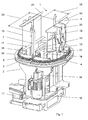
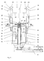
- the in the FIGS. 1 and 2 shown stacking device 1 has a frame 2, which has a substantially horizontal table 3, on which two endless drive members 4, 5 are mounted.
- a lift 12 is arranged, which has two inner lift plates 13 and two outer lift plates 14.
- the lift 12 allows a reduction in the drop height of the printed products 9.
- the stack 8 may consist of several layers of printed products 9, which are each rotated by 180 ° to each other.
- the table 3 can be rotated by means of an actuating cylinder 11 about a vertical axis. This is called so-called crosslapping and is well known to those skilled in the art.
- a stack formed in this way 8 can be pressed by a lift of the lift 12 against pressing flaps 20, that is compacted.
- FIG. 2 are two on or swing at serving for format setting of the stack 8 limiting elements 19 arranged press flaps 20 shown.
- a pivoted, active position is shown on the left side of the drawing.
- For pressing the press flaps 20 are pivoted by means of actuating cylinder 21 in the direction of the arrow 23, respectively.
- the actuating cylinder 21 engage with retractable piston rods 22 each on a compression flap 20.
- each press flap 20 protrudes inward with a press plate 24 via the respective limiting element 19, so that the stack 8 to be squeezed out can be applied against the two press plates 24 by appropriately raising the lift 12.
- the lift 12 is again in the in the FIGS. 1 and 2 Shut down rest position shown.
- the two inner lift plates 13 are arranged at a distance from one another, so that there is a linear passage 33 between them. These inner lift plates 13 are respectively arranged on vertically extending plates 37, which are connected to a driver 15.
- the outer lift plates 14 also have downwardly extending plates 36 which are slidably mounted on a horizontally extending guide 16 and a vertically extending guide 17.
- the inner lift plates 13 can only be moved vertically, while the outer lift plates 14 can be moved both vertically and horizontally.
- the horizontal movement makes it possible to change the distance indicated by double arrows 18 between the two outer lift plates 14.
- By adjusting the outer lift plates 14 at the same time attached to this limiting elements 19 are adjusted. These limiting elements 19 are plate-shaped and extend beyond the table 3 also upwards.
- FIG. 1 indicated format width 26 are set.
- the outer lift plates 14 are adjusted together with the limiting elements 19 accordingly.
- the adjustment can take place via actuators, not shown here and by means of a control, not shown here.
- the drive member 4 is driven by an engine 10 via a transmission 38.
- the engagement on the drive member 4 takes place for example via a in Fig. 3a indicated drive wheel 30. This is stored in table 3.
- the drive member 5 is driven by a further motor, not shown here, which, like the engine 10, has a transmission.
- the engagement also preferably takes place via a drive wheel 30.
- the two drive elements 4, 5 are designed as link chains, but other endless drive elements are also conceivable here. Both drive elements 4, 5 are each a deflection wheel 29 ( Fig. 3a ) and form in plan view essentially a semicircle segment.
- a first ejection member 6 is fixed, which is rod-shaped or finger-shaped and protrudes vertically from the table 3 upwards.
- a second ejection member 7 is fixed, which is formed substantially the same as the ejection member 6.
- the distance between the two ejection members 6, 7 determines the in FIG. 1 indicated back length 25 of a stack to be ejected 8. Since the two drive members 4, 5 are driven independently of each other, the distance between the two ejection members 6, 7 can be adjusted continuously. The adjustment takes place via the two aforementioned motors 10 which are connected to a controller, not shown here.
- the passage 33 between the two inner lift plates 13 is so far that the two ejection elements 6, 7 can pass through this passage 33.
- the two ejection organs 6, 7 according to FIG. 2 each guided with a sliding guide 28 linearly in a guide rail 27 formed as a guide rail, which extends horizontally and rectilinearly in the plane of the table 3.
- a guide rail 27 formed as a guide rail, which extends horizontally and rectilinearly in the plane of the table 3.
- the ejection elements 6, 7 are each attached to two or more superposed drive members.
- the two ejection elements 6, 7 each have not one, but two or more than two upwardly projecting rods or fingers or in which more than one ejection member to a drive member 4, 5 is fixed. If the table 3 is rotated about a vertical axis by 180 °, as mentioned above, then the ejection elements 6, 7 rotate accordingly.
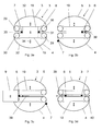
- the ejection is described below on the basis of FIGS. 3a to 3d explained in more detail.
- FIG. 3a schematically shows a plan view of the table 3 on which a stack 8 is formed.
- This stack 8 is located between two limiting elements 19 and between the first ejection element 6 and the second ejection element 7.
- the distances between the two limiting elements 19 and between the two ejection elements 6, 7 correspond to the format of the stack 8 or its back length 25 and format width 26
- Double arrows 34 indicate the adjustability of the limiting elements 19.
- the first ejection member 6 is connected to the drive member 5 and the second ejection member 7 to the drive member 4.
- These drive members 4, 5 are arranged as shown approximately semicircular segmented and each have a substantial straight track section 31 and a curved track section 32.
- the straight track sections 31 form the passage 33.
- the curved track sections 32 may also have a different shape to the ejected stack 8 running around, for example, formed with rounded corners rectangular or elliptical path.
- the two ejection elements 6, 7 are within the passage 33 and the stack 8 is ready for ejection.
- the lift 12 is located in the FIGS. 1 and 2 shown lower position.
- the first ejection member 7 limiting the back length 25 of the stack 8, with the drive member 4 is removed from the stack 8, as shown drives out of the passage 33 and is laterally guided in the curved path portion 32 of the drive member 4.
- the first ejection element 6 starts the stack 8 in an ejection direction 39, ie to eject to the left and is thus in the FIG. 3b moved to the left.
- the second ejection member 7 is located on the curved path section 32, for example in the in Figure 3c shown position. Meanwhile, the first ejector 6, the stack 8 according to Figure 3c already largely expelled. In this ejection movement of the stack 8 is guided between the two limiting elements 19. The first ejection member 6 moves from the illustration in FIG Figure 3c even further to the left and pushes the stack 8 in the ejection direction 39 completely from the table 3, so that the stack 8 can be taken for example by a transport device, not shown here. The second ejection member 7 is now in the in 3d figure shown position, which that of the first ejection member 6 according to FIG. 3a equivalent.
- the first ejection member 6 is by reversing its direction of movement by the drive member 5 in the in 3d figure shown position. This position corresponds to that of the second ejection member 7 according to FIG. 3a , To move the first ejection member 6 in the in 3d figure shown position, the drive member 5 is thus driven reversing. When ejecting the drive member 4 is always moved in the same direction. The drive member 5, however, is first moved counterclockwise in the clockwise direction and after the ejection of the stack 8.
- the ejection of the stack 8 thus takes place according to the FIGS. 3a to 3c from right to left. But it is also possible to eject from left to right, in which case the ejection organs 6, 7 each take over the other function.
- the possible ejection directions 39, 40 are shown, It is essential as can be seen that the two drive members 4, 5 can be moved independently controlled. Each of the two ejection elements 6, 7 can thus be moved at different speeds and also the direction of movement can be changed at any time. Accordingly, the distance between the two ejection elements 6, 7 can be adjusted by appropriate movements of the drive members 4, 5.
- the main advantages here are a shorter cycle time when ejecting and the possible adaptation to different back lengths by corresponding adjustment of the two ejection elements 6, 7.
Landscapes
- Engineering & Computer Science (AREA)
- Mechanical Engineering (AREA)
- Pile Receivers (AREA)
- Forming Counted Batches (AREA)
Priority Applications (4)
| Application Number | Priority Date | Filing Date | Title |
|---|---|---|---|
| EP08405293.5A EP2192067B1 (fr) | 2008-11-28 | 2008-11-28 | Dispositif d'empilement pour produits d'impression |
| JP2009262571A JP5520577B2 (ja) | 2008-11-28 | 2009-11-18 | 印刷製品用の堆積装置 |
| CN200910225728.3A CN101746637B (zh) | 2008-11-28 | 2009-11-27 | 用于印刷制品的堆垛装置 |
| US12/627,661 US8573920B2 (en) | 2008-11-28 | 2009-11-30 | Stacking device for print products |
Applications Claiming Priority (1)
| Application Number | Priority Date | Filing Date | Title |
|---|---|---|---|
| EP08405293.5A EP2192067B1 (fr) | 2008-11-28 | 2008-11-28 | Dispositif d'empilement pour produits d'impression |
Publications (2)
| Publication Number | Publication Date |
|---|---|
| EP2192067A1 true EP2192067A1 (fr) | 2010-06-02 |
| EP2192067B1 EP2192067B1 (fr) | 2013-09-18 |
Family
ID=40551369
Family Applications (1)
| Application Number | Title | Priority Date | Filing Date |
|---|---|---|---|
| EP08405293.5A Not-in-force EP2192067B1 (fr) | 2008-11-28 | 2008-11-28 | Dispositif d'empilement pour produits d'impression |
Country Status (4)
| Country | Link |
|---|---|
| US (1) | US8573920B2 (fr) |
| EP (1) | EP2192067B1 (fr) |
| JP (1) | JP5520577B2 (fr) |
| CN (1) | CN101746637B (fr) |
Cited By (2)
| Publication number | Priority date | Publication date | Assignee | Title |
|---|---|---|---|---|
| WO2012038013A1 (fr) * | 2010-09-22 | 2012-03-29 | Bobst Sa | Dispositif de transport de paquets pour machine de cerclage |
| CN107471640A (zh) * | 2017-09-30 | 2017-12-15 | 窦鹤鸿 | 一种激光驱动机构及3d打印机 |
Families Citing this family (2)
| Publication number | Priority date | Publication date | Assignee | Title |
|---|---|---|---|---|
| JP2759286B2 (ja) | 1989-09-12 | 1998-05-28 | コニカ株式会社 | カラー画像形成装置 |
| US12145810B2 (en) * | 2022-06-24 | 2024-11-19 | The Henry Group | Apparatus for stacking taco shells |
Citations (8)
| Publication number | Priority date | Publication date | Assignee | Title |
|---|---|---|---|---|
| US4103785A (en) | 1976-08-18 | 1978-08-01 | Wiseman Raymond L | Apparatus for rotating and discharging articles |
| US5092236A (en) * | 1990-06-06 | 1992-03-03 | Quipp Systems, Inc. | Method and apparatus for stacking, aligning and compressing signatures |
| US5338149A (en) | 1984-04-02 | 1994-08-16 | Idab Incorporated | Signature stacker |
| EP0626330A2 (fr) * | 1993-05-24 | 1994-11-30 | Am International Incorporated | Appareil pour la manutention de cahiers |
| EP0829441A1 (fr) | 1996-09-11 | 1998-03-18 | Grapha-Holding Ag | Dispositif pour éjecter des feuilles imprimés et empilés |
| US5868548A (en) | 1996-02-26 | 1999-02-09 | Total Mailroom Support, Inc. | Stacking device for printer products and the like |
| EP1362817A1 (fr) | 2002-05-17 | 2003-11-19 | Müller Martini Holding AG | Dispositif pour pousser des produit imprimés empilés sur une table |
| EP1445224A1 (fr) * | 2003-01-14 | 2004-08-11 | Ferag AG | Dispositif pour former des piles d'articles plats |
Family Cites Families (14)
| Publication number | Priority date | Publication date | Assignee | Title |
|---|---|---|---|---|
| US2993583A (en) * | 1958-06-03 | 1961-07-25 | Toronto Star Ltd | Roller slat conveyor diverter mechanism |
| DE1973346U (de) * | 1967-07-18 | 1967-11-23 | August Wickersheim K G | Vorrichtung zum zufuehren von verpackungsgut, insbesondere von zu stapeln zusammengefassten zeitschriften, zeitungen und dgl., zu verpackungseinrichtungen. |
| US3533213A (en) * | 1969-01-02 | 1970-10-13 | Tech Art Inc | Packing machine |
| US3643816A (en) * | 1970-05-25 | 1972-02-22 | Weber & Co Inc H G | Stacker for bags and the like |
| JPS5427018Y2 (fr) * | 1975-10-16 | 1979-09-04 | ||
| US4085566A (en) * | 1977-03-16 | 1978-04-25 | Multifold-International, Inc. | Machine for stacking and casing articles |
| FR2561876B1 (fr) * | 1984-04-02 | 1986-07-18 | Tabacs & Allumettes Ind | Dispositif d'alimentation d'un poste d'operation comme l'identification ou la mesure d'au moins une caracteristique d'une succession d'articles semblables |
| JPH0543002Y2 (fr) * | 1986-02-17 | 1993-10-28 | ||
| US5312223A (en) * | 1993-03-19 | 1994-05-17 | Am International, Inc. | Apparatus for stacking signatures |
| DE4408780A1 (de) * | 1994-03-15 | 1995-09-21 | Gunter Gaemmerler | Verfahren zum Stapeln von Flächengebilden |
| US6106219A (en) * | 1999-01-20 | 2000-08-22 | John Robert Newsome | Stack forming and conveying apparatus |
| ES2170736T3 (es) * | 2000-06-30 | 2004-07-16 | SEGBERT GMBH & CO. KG | Dispositivo para formar y alinear paquetes de productos de imprenta apilados en forma suelta. |
| EP1593633B1 (fr) * | 2004-05-05 | 2008-10-15 | Müller Martini Holding AG | Dispositif pour empiler des articles imprimés |
| DK1826164T3 (da) * | 2006-02-27 | 2012-12-17 | Ferag Ag | Lagpresse |
-
2008
- 2008-11-28 EP EP08405293.5A patent/EP2192067B1/fr not_active Not-in-force
-
2009
- 2009-11-18 JP JP2009262571A patent/JP5520577B2/ja not_active Expired - Fee Related
- 2009-11-27 CN CN200910225728.3A patent/CN101746637B/zh not_active Expired - Fee Related
- 2009-11-30 US US12/627,661 patent/US8573920B2/en not_active Expired - Fee Related
Patent Citations (8)
| Publication number | Priority date | Publication date | Assignee | Title |
|---|---|---|---|---|
| US4103785A (en) | 1976-08-18 | 1978-08-01 | Wiseman Raymond L | Apparatus for rotating and discharging articles |
| US5338149A (en) | 1984-04-02 | 1994-08-16 | Idab Incorporated | Signature stacker |
| US5092236A (en) * | 1990-06-06 | 1992-03-03 | Quipp Systems, Inc. | Method and apparatus for stacking, aligning and compressing signatures |
| EP0626330A2 (fr) * | 1993-05-24 | 1994-11-30 | Am International Incorporated | Appareil pour la manutention de cahiers |
| US5868548A (en) | 1996-02-26 | 1999-02-09 | Total Mailroom Support, Inc. | Stacking device for printer products and the like |
| EP0829441A1 (fr) | 1996-09-11 | 1998-03-18 | Grapha-Holding Ag | Dispositif pour éjecter des feuilles imprimés et empilés |
| EP1362817A1 (fr) | 2002-05-17 | 2003-11-19 | Müller Martini Holding AG | Dispositif pour pousser des produit imprimés empilés sur une table |
| EP1445224A1 (fr) * | 2003-01-14 | 2004-08-11 | Ferag AG | Dispositif pour former des piles d'articles plats |
Cited By (5)
| Publication number | Priority date | Publication date | Assignee | Title |
|---|---|---|---|---|
| WO2012038013A1 (fr) * | 2010-09-22 | 2012-03-29 | Bobst Sa | Dispositif de transport de paquets pour machine de cerclage |
| KR101473126B1 (ko) * | 2010-09-22 | 2014-12-15 | 봅스트 맥스 에스에이 | 스트래핑 기계용 번들들을 이송하기 위한 기기 |
| US8978870B2 (en) | 2010-09-22 | 2015-03-17 | Bobst Mex Sa | Device for conveying bundles for a strapping machine |
| CN107471640A (zh) * | 2017-09-30 | 2017-12-15 | 窦鹤鸿 | 一种激光驱动机构及3d打印机 |
| CN107471640B (zh) * | 2017-09-30 | 2024-06-04 | 窦鹤鸿 | 一种激光驱动机构及3d打印机 |
Also Published As
| Publication number | Publication date |
|---|---|
| JP5520577B2 (ja) | 2014-06-11 |
| US20100135762A1 (en) | 2010-06-03 |
| CN101746637A (zh) | 2010-06-23 |
| JP2010126366A (ja) | 2010-06-10 |
| EP2192067B1 (fr) | 2013-09-18 |
| US8573920B2 (en) | 2013-11-05 |
| CN101746637B (zh) | 2015-06-03 |
Similar Documents
| Publication | Publication Date | Title |
|---|---|---|
| DE1936012C2 (de) | Vorrichtung zum Schmieden von Kurbelhüben in einer vertikal wirkenden Schmiedepresse | |
| DE69702274T2 (de) | Vorrichtung zum Sammeln und Stapeln von Schichtwerkstoffen, und ein Stapelverfahren | |
| DE102008051026A1 (de) | Transportmittel und Verpackungsmaschine für Folienbreitenanpassung | |
| EP2923852B1 (fr) | Dispositif de formage de couvertures de livre | |
| DE10206773C1 (de) | Vorrichtung zum Vorschieben von Werkstücken mit Greiferschienen | |
| WO2003099541A1 (fr) | Installation de thermoformage pour la production de corps façonnes a partir d'un film de plastique, et procede de production de tels corps | |
| EP2581331B1 (fr) | Dispositif et procédé d'alignement de produits | |
| EP2192067B1 (fr) | Dispositif d'empilement pour produits d'impression | |
| EP2939965B1 (fr) | Dispositif de poussée pour un dispositif de palettisation avec un poussoir, un guide d'arrêt en butée et deux guides latéraux | |
| EP2086844A1 (fr) | Machine d'emballage à entraînement pneumatique/hydraulique ajustable | |
| EP2143550A1 (fr) | Dispositif de fabrication de corps creux en feuilles de plastique déformables thermoplastiques | |
| DE3016956A1 (de) | Planstanzmaschine | |
| EP3964465A1 (fr) | Dispositif de pliage pour une pièce découpée plane | |
| DE1602607A1 (de) | Foerdervorrichtung | |
| DE60318360T2 (de) | Rill- und Falzmaschine für Kartonplatten | |
| DE3301451A1 (de) | Steuervorrichtung fuer eine kartonversiegel- und/oder -verschliessmaschine | |
| DE2804107A1 (de) | Verfahren und einrichtung zur verbindung aneinanderliegender materialschichten | |
| DE2228808C2 (de) | Mehrfachfaltvorrichtung | |
| DE102011103289B4 (de) | Arbeitsverfahren und Vorrichtung zum Zusammenlegen von Komponenten von Sandwich-Rahmentüren und Sandwich-Rahmen-Möbelbauplatten | |
| AT406755B (de) | Vorrichtung zum öffnen von schlauchförmigen sackkörpern | |
| DE2109216B2 (de) | Vorrichtung zur Herstellung von Formlöchern in einer Materialbahn, z.B. von Streckmetall | |
| EP0829441B1 (fr) | Dispositif pour éjecter des feuilles imprimées et empilées | |
| DE19620597C2 (de) | Vorrichtung zur Bearbeitung von Lagenmaterial | |
| DE3703951C2 (de) | Wendevorrichtung für Papierstapel oder dergl. | |
| DE3011875C2 (de) | Rollenfördereinrichtung mit veränderbarer Förderbreite |
Legal Events
| Date | Code | Title | Description |
|---|---|---|---|
| PUAI | Public reference made under article 153(3) epc to a published international application that has entered the european phase |
Free format text: ORIGINAL CODE: 0009012 |
|
| AK | Designated contracting states |
Kind code of ref document: A1 Designated state(s): AT BE BG CH CY CZ DE DK EE ES FI FR GB GR HR HU IE IS IT LI LT LU LV MC MT NL NO PL PT RO SE SI SK TR |
|
| AX | Request for extension of the european patent |
Extension state: AL BA MK RS |
|
| 17P | Request for examination filed |
Effective date: 20100915 |
|
| 17Q | First examination report despatched |
Effective date: 20101116 |
|
| R17C | First examination report despatched (corrected) |
Effective date: 20101123 |
|
| AKX | Designation fees paid |
Designated state(s): AT BE BG CH CY CZ DE DK EE ES FI FR GB GR HR HU IE IS IT LI LT LU LV MC MT NL NO PL PT RO SE SI SK TR |
|
| GRAP | Despatch of communication of intention to grant a patent |
Free format text: ORIGINAL CODE: EPIDOSNIGR1 |
|
| INTG | Intention to grant announced |
Effective date: 20130531 |
|
| GRAS | Grant fee paid |
Free format text: ORIGINAL CODE: EPIDOSNIGR3 |
|
| GRAA | (expected) grant |
Free format text: ORIGINAL CODE: 0009210 |
|
| AK | Designated contracting states |
Kind code of ref document: B1 Designated state(s): AT BE BG CH CY CZ DE DK EE ES FI FR GB GR HR HU IE IS IT LI LT LU LV MC MT NL NO PL PT RO SE SI SK TR |
|
| REG | Reference to a national code |
Ref country code: GB Ref legal event code: FG4D Free format text: NOT ENGLISH |
|
| REG | Reference to a national code |
Ref country code: CH Ref legal event code: EP |
|
| REG | Reference to a national code |
Ref country code: IE Ref legal event code: FG4D Free format text: LANGUAGE OF EP DOCUMENT: GERMAN |
|
| REG | Reference to a national code |
Ref country code: AT Ref legal event code: REF Ref document number: 632638 Country of ref document: AT Kind code of ref document: T Effective date: 20131015 |
|
| REG | Reference to a national code |
Ref country code: DE Ref legal event code: R096 Ref document number: 502008010684 Country of ref document: DE Effective date: 20131114 |
|
| PG25 | Lapsed in a contracting state [announced via postgrant information from national office to epo] |
Ref country code: HR Free format text: LAPSE BECAUSE OF FAILURE TO SUBMIT A TRANSLATION OF THE DESCRIPTION OR TO PAY THE FEE WITHIN THE PRESCRIBED TIME-LIMIT Effective date: 20130918 Ref country code: SE Free format text: LAPSE BECAUSE OF FAILURE TO SUBMIT A TRANSLATION OF THE DESCRIPTION OR TO PAY THE FEE WITHIN THE PRESCRIBED TIME-LIMIT Effective date: 20130918 Ref country code: CY Free format text: LAPSE BECAUSE OF FAILURE TO SUBMIT A TRANSLATION OF THE DESCRIPTION OR TO PAY THE FEE WITHIN THE PRESCRIBED TIME-LIMIT Effective date: 20130828 Ref country code: LT Free format text: LAPSE BECAUSE OF FAILURE TO SUBMIT A TRANSLATION OF THE DESCRIPTION OR TO PAY THE FEE WITHIN THE PRESCRIBED TIME-LIMIT Effective date: 20130918 Ref country code: NO Free format text: LAPSE BECAUSE OF FAILURE TO SUBMIT A TRANSLATION OF THE DESCRIPTION OR TO PAY THE FEE WITHIN THE PRESCRIBED TIME-LIMIT Effective date: 20131218 |
|
| REG | Reference to a national code |
Ref country code: NL Ref legal event code: VDEP Effective date: 20130918 |
|
| REG | Reference to a national code |
Ref country code: LT Ref legal event code: MG4D |
|
| PG25 | Lapsed in a contracting state [announced via postgrant information from national office to epo] |
Ref country code: FI Free format text: LAPSE BECAUSE OF FAILURE TO SUBMIT A TRANSLATION OF THE DESCRIPTION OR TO PAY THE FEE WITHIN THE PRESCRIBED TIME-LIMIT Effective date: 20130918 Ref country code: SI Free format text: LAPSE BECAUSE OF FAILURE TO SUBMIT A TRANSLATION OF THE DESCRIPTION OR TO PAY THE FEE WITHIN THE PRESCRIBED TIME-LIMIT Effective date: 20130918 Ref country code: GR Free format text: LAPSE BECAUSE OF FAILURE TO SUBMIT A TRANSLATION OF THE DESCRIPTION OR TO PAY THE FEE WITHIN THE PRESCRIBED TIME-LIMIT Effective date: 20131219 Ref country code: LV Free format text: LAPSE BECAUSE OF FAILURE TO SUBMIT A TRANSLATION OF THE DESCRIPTION OR TO PAY THE FEE WITHIN THE PRESCRIBED TIME-LIMIT Effective date: 20130918 |
|
| PG25 | Lapsed in a contracting state [announced via postgrant information from national office to epo] |
Ref country code: CY Free format text: LAPSE BECAUSE OF FAILURE TO SUBMIT A TRANSLATION OF THE DESCRIPTION OR TO PAY THE FEE WITHIN THE PRESCRIBED TIME-LIMIT Effective date: 20130918 |
|
| PG25 | Lapsed in a contracting state [announced via postgrant information from national office to epo] |
Ref country code: CZ Free format text: LAPSE BECAUSE OF FAILURE TO SUBMIT A TRANSLATION OF THE DESCRIPTION OR TO PAY THE FEE WITHIN THE PRESCRIBED TIME-LIMIT Effective date: 20130918 Ref country code: NL Free format text: LAPSE BECAUSE OF FAILURE TO SUBMIT A TRANSLATION OF THE DESCRIPTION OR TO PAY THE FEE WITHIN THE PRESCRIBED TIME-LIMIT Effective date: 20130918 Ref country code: RO Free format text: LAPSE BECAUSE OF FAILURE TO SUBMIT A TRANSLATION OF THE DESCRIPTION OR TO PAY THE FEE WITHIN THE PRESCRIBED TIME-LIMIT Effective date: 20130918 Ref country code: IS Free format text: LAPSE BECAUSE OF FAILURE TO SUBMIT A TRANSLATION OF THE DESCRIPTION OR TO PAY THE FEE WITHIN THE PRESCRIBED TIME-LIMIT Effective date: 20140118 Ref country code: SK Free format text: LAPSE BECAUSE OF FAILURE TO SUBMIT A TRANSLATION OF THE DESCRIPTION OR TO PAY THE FEE WITHIN THE PRESCRIBED TIME-LIMIT Effective date: 20130918 Ref country code: EE Free format text: LAPSE BECAUSE OF FAILURE TO SUBMIT A TRANSLATION OF THE DESCRIPTION OR TO PAY THE FEE WITHIN THE PRESCRIBED TIME-LIMIT Effective date: 20130918 |
|
| PG25 | Lapsed in a contracting state [announced via postgrant information from national office to epo] |
Ref country code: PL Free format text: LAPSE BECAUSE OF FAILURE TO SUBMIT A TRANSLATION OF THE DESCRIPTION OR TO PAY THE FEE WITHIN THE PRESCRIBED TIME-LIMIT Effective date: 20130918 Ref country code: ES Free format text: LAPSE BECAUSE OF FAILURE TO SUBMIT A TRANSLATION OF THE DESCRIPTION OR TO PAY THE FEE WITHIN THE PRESCRIBED TIME-LIMIT Effective date: 20130918 |
|
| BERE | Be: lapsed |
Owner name: MULLER MARTINI HOLDING A.G. Effective date: 20131130 |
|
| REG | Reference to a national code |
Ref country code: DE Ref legal event code: R097 Ref document number: 502008010684 Country of ref document: DE |
|
| PG25 | Lapsed in a contracting state [announced via postgrant information from national office to epo] |
Ref country code: PT Free format text: LAPSE BECAUSE OF FAILURE TO SUBMIT A TRANSLATION OF THE DESCRIPTION OR TO PAY THE FEE WITHIN THE PRESCRIBED TIME-LIMIT Effective date: 20140120 |
|
| PLBE | No opposition filed within time limit |
Free format text: ORIGINAL CODE: 0009261 |
|
| STAA | Information on the status of an ep patent application or granted ep patent |
Free format text: STATUS: NO OPPOSITION FILED WITHIN TIME LIMIT |
|
| PG25 | Lapsed in a contracting state [announced via postgrant information from national office to epo] |
Ref country code: MC Free format text: LAPSE BECAUSE OF FAILURE TO SUBMIT A TRANSLATION OF THE DESCRIPTION OR TO PAY THE FEE WITHIN THE PRESCRIBED TIME-LIMIT Effective date: 20130918 |
|
| 26N | No opposition filed |
Effective date: 20140619 |
|
| REG | Reference to a national code |
Ref country code: IE Ref legal event code: MM4A |
|
| PG25 | Lapsed in a contracting state [announced via postgrant information from national office to epo] |
Ref country code: DK Free format text: LAPSE BECAUSE OF FAILURE TO SUBMIT A TRANSLATION OF THE DESCRIPTION OR TO PAY THE FEE WITHIN THE PRESCRIBED TIME-LIMIT Effective date: 20130918 Ref country code: BE Free format text: LAPSE BECAUSE OF NON-PAYMENT OF DUE FEES Effective date: 20131130 |
|
| REG | Reference to a national code |
Ref country code: DE Ref legal event code: R097 Ref document number: 502008010684 Country of ref document: DE Effective date: 20140619 |
|
| PG25 | Lapsed in a contracting state [announced via postgrant information from national office to epo] |
Ref country code: IE Free format text: LAPSE BECAUSE OF NON-PAYMENT OF DUE FEES Effective date: 20131128 |
|
| REG | Reference to a national code |
Ref country code: AT Ref legal event code: MM01 Ref document number: 632638 Country of ref document: AT Kind code of ref document: T Effective date: 20131128 |
|
| PG25 | Lapsed in a contracting state [announced via postgrant information from national office to epo] |
Ref country code: AT Free format text: LAPSE BECAUSE OF NON-PAYMENT OF DUE FEES Effective date: 20131128 |
|
| PG25 | Lapsed in a contracting state [announced via postgrant information from national office to epo] |
Ref country code: TR Free format text: LAPSE BECAUSE OF FAILURE TO SUBMIT A TRANSLATION OF THE DESCRIPTION OR TO PAY THE FEE WITHIN THE PRESCRIBED TIME-LIMIT Effective date: 20130918 |
|
| PG25 | Lapsed in a contracting state [announced via postgrant information from national office to epo] |
Ref country code: HU Free format text: LAPSE BECAUSE OF FAILURE TO SUBMIT A TRANSLATION OF THE DESCRIPTION OR TO PAY THE FEE WITHIN THE PRESCRIBED TIME-LIMIT; INVALID AB INITIO Effective date: 20081128 Ref country code: LU Free format text: LAPSE BECAUSE OF NON-PAYMENT OF DUE FEES Effective date: 20131128 Ref country code: BG Free format text: LAPSE BECAUSE OF FAILURE TO SUBMIT A TRANSLATION OF THE DESCRIPTION OR TO PAY THE FEE WITHIN THE PRESCRIBED TIME-LIMIT Effective date: 20130918 |
|
| PG25 | Lapsed in a contracting state [announced via postgrant information from national office to epo] |
Ref country code: MT Free format text: LAPSE BECAUSE OF FAILURE TO SUBMIT A TRANSLATION OF THE DESCRIPTION OR TO PAY THE FEE WITHIN THE PRESCRIBED TIME-LIMIT Effective date: 20130918 |
|
| REG | Reference to a national code |
Ref country code: FR Ref legal event code: PLFP Year of fee payment: 8 |
|
| PGFP | Annual fee paid to national office [announced via postgrant information from national office to epo] |
Ref country code: GB Payment date: 20151123 Year of fee payment: 8 |
|
| PGFP | Annual fee paid to national office [announced via postgrant information from national office to epo] |
Ref country code: FR Payment date: 20151123 Year of fee payment: 8 |
|
| PGFP | Annual fee paid to national office [announced via postgrant information from national office to epo] |
Ref country code: IT Payment date: 20151130 Year of fee payment: 8 |
|
| GBPC | Gb: european patent ceased through non-payment of renewal fee |
Effective date: 20161128 |
|
| REG | Reference to a national code |
Ref country code: FR Ref legal event code: ST Effective date: 20170731 |
|
| PG25 | Lapsed in a contracting state [announced via postgrant information from national office to epo] |
Ref country code: FR Free format text: LAPSE BECAUSE OF NON-PAYMENT OF DUE FEES Effective date: 20161130 Ref country code: IT Free format text: LAPSE BECAUSE OF NON-PAYMENT OF DUE FEES Effective date: 20161128 |
|
| PG25 | Lapsed in a contracting state [announced via postgrant information from national office to epo] |
Ref country code: GB Free format text: LAPSE BECAUSE OF NON-PAYMENT OF DUE FEES Effective date: 20161128 |
|
| PGFP | Annual fee paid to national office [announced via postgrant information from national office to epo] |
Ref country code: DE Payment date: 20181116 Year of fee payment: 11 |
|
| PGFP | Annual fee paid to national office [announced via postgrant information from national office to epo] |
Ref country code: CH Payment date: 20190222 Year of fee payment: 11 |
|
| REG | Reference to a national code |
Ref country code: DE Ref legal event code: R119 Ref document number: 502008010684 Country of ref document: DE |
|
| REG | Reference to a national code |
Ref country code: CH Ref legal event code: PL |
|
| PG25 | Lapsed in a contracting state [announced via postgrant information from national office to epo] |
Ref country code: CH Free format text: LAPSE BECAUSE OF NON-PAYMENT OF DUE FEES Effective date: 20191130 Ref country code: LI Free format text: LAPSE BECAUSE OF NON-PAYMENT OF DUE FEES Effective date: 20191130 |
|
| PG25 | Lapsed in a contracting state [announced via postgrant information from national office to epo] |
Ref country code: DE Free format text: LAPSE BECAUSE OF NON-PAYMENT OF DUE FEES Effective date: 20200603 |