EP2192405A1 - Procédé de contrôle d'additifs de stabilisateur dans un métal autocatalytique et électrolytes à placage d'alliage métallique - Google Patents
Procédé de contrôle d'additifs de stabilisateur dans un métal autocatalytique et électrolytes à placage d'alliage métallique Download PDFInfo
- Publication number
- EP2192405A1 EP2192405A1 EP08075906A EP08075906A EP2192405A1 EP 2192405 A1 EP2192405 A1 EP 2192405A1 EP 08075906 A EP08075906 A EP 08075906A EP 08075906 A EP08075906 A EP 08075906A EP 2192405 A1 EP2192405 A1 EP 2192405A1
- Authority
- EP
- European Patent Office
- Prior art keywords
- faradaic current
- metal
- electroless
- current
- electrolyte
- Prior art date
- Legal status (The legal status is an assumption and is not a legal conclusion. Google has not performed a legal analysis and makes no representation as to the accuracy of the status listed.)
- Granted
Links
- 239000003792 electrolyte Substances 0.000 title claims abstract description 106
- 239000000654 additive Substances 0.000 title claims abstract description 94
- 239000003381 stabilizer Substances 0.000 title claims abstract description 90
- 238000007747 plating Methods 0.000 title claims abstract description 66
- 238000000034 method Methods 0.000 title claims abstract description 59
- 229910052751 metal Inorganic materials 0.000 title claims abstract description 39
- 239000002184 metal Substances 0.000 title claims abstract description 39
- 229910001092 metal group alloy Inorganic materials 0.000 title claims abstract description 28
- 230000000996 additive effect Effects 0.000 claims abstract description 56
- 238000005259 measurement Methods 0.000 claims abstract description 34
- 230000003750 conditioning effect Effects 0.000 claims abstract description 5
- 239000010949 copper Substances 0.000 claims description 49
- RYGMFSIKBFXOCR-UHFFFAOYSA-N Copper Chemical compound [Cu] RYGMFSIKBFXOCR-UHFFFAOYSA-N 0.000 claims description 48
- 229910052802 copper Inorganic materials 0.000 claims description 48
- PXHVJJICTQNCMI-UHFFFAOYSA-N Nickel Chemical compound [Ni] PXHVJJICTQNCMI-UHFFFAOYSA-N 0.000 claims description 28
- 239000003638 chemical reducing agent Substances 0.000 claims description 23
- 230000009467 reduction Effects 0.000 claims description 18
- 229910052759 nickel Inorganic materials 0.000 claims description 14
- 238000007254 oxidation reaction Methods 0.000 claims description 7
- KDLHZDBZIXYQEI-UHFFFAOYSA-N Palladium Chemical compound [Pd] KDLHZDBZIXYQEI-UHFFFAOYSA-N 0.000 claims description 6
- 230000003647 oxidation Effects 0.000 claims description 6
- 238000004832 voltammetry Methods 0.000 claims description 4
- BQCADISMDOOEFD-UHFFFAOYSA-N Silver Chemical compound [Ag] BQCADISMDOOEFD-UHFFFAOYSA-N 0.000 claims description 3
- 229910045601 alloy Inorganic materials 0.000 claims description 3
- 239000000956 alloy Substances 0.000 claims description 3
- PCHJSUWPFVWCPO-UHFFFAOYSA-N gold Chemical compound [Au] PCHJSUWPFVWCPO-UHFFFAOYSA-N 0.000 claims description 3
- 229910052737 gold Inorganic materials 0.000 claims description 3
- 239000010931 gold Substances 0.000 claims description 3
- 229910052763 palladium Inorganic materials 0.000 claims description 3
- 229910052709 silver Inorganic materials 0.000 claims description 3
- 239000004332 silver Substances 0.000 claims description 3
- KJTLSVCANCCWHF-UHFFFAOYSA-N Ruthenium Chemical compound [Ru] KJTLSVCANCCWHF-UHFFFAOYSA-N 0.000 claims description 2
- ATJFFYVFTNAWJD-UHFFFAOYSA-N Tin Chemical compound [Sn] ATJFFYVFTNAWJD-UHFFFAOYSA-N 0.000 claims description 2
- 230000001143 conditioned effect Effects 0.000 claims description 2
- 238000007654 immersion Methods 0.000 claims description 2
- 229910052707 ruthenium Inorganic materials 0.000 claims description 2
- 239000011135 tin Substances 0.000 claims description 2
- 229910052718 tin Inorganic materials 0.000 claims description 2
- 239000000126 substance Substances 0.000 claims 1
- 239000000543 intermediate Substances 0.000 abstract description 8
- 230000003993 interaction Effects 0.000 abstract description 5
- WSFSSNUMVMOOMR-UHFFFAOYSA-N Formaldehyde Chemical compound O=C WSFSSNUMVMOOMR-UHFFFAOYSA-N 0.000 description 45
- 239000000203 mixture Substances 0.000 description 29
- XFXPMWWXUTWYJX-UHFFFAOYSA-N Cyanide Chemical compound N#[C-] XFXPMWWXUTWYJX-UHFFFAOYSA-N 0.000 description 22
- 238000007772 electroless plating Methods 0.000 description 15
- 238000006722 reduction reaction Methods 0.000 description 15
- 229910021607 Silver chloride Inorganic materials 0.000 description 12
- HEMHJVSKTPXQMS-UHFFFAOYSA-M Sodium hydroxide Chemical compound [OH-].[Na+] HEMHJVSKTPXQMS-UHFFFAOYSA-M 0.000 description 12
- HKZLPVFGJNLROG-UHFFFAOYSA-M silver monochloride Chemical compound [Cl-].[Ag+] HKZLPVFGJNLROG-UHFFFAOYSA-M 0.000 description 12
- BASFCYQUMIYNBI-UHFFFAOYSA-N platinum Chemical compound [Pt] BASFCYQUMIYNBI-UHFFFAOYSA-N 0.000 description 11
- 238000012360 testing method Methods 0.000 description 11
- YXIWHUQXZSMYRE-UHFFFAOYSA-N 1,3-benzothiazole-2-thiol Chemical compound C1=CC=C2SC(S)=NC2=C1 YXIWHUQXZSMYRE-UHFFFAOYSA-N 0.000 description 9
- ACVYVLVWPXVTIT-UHFFFAOYSA-M phosphinate Chemical compound [O-][PH2]=O ACVYVLVWPXVTIT-UHFFFAOYSA-M 0.000 description 8
- 239000000243 solution Substances 0.000 description 8
- JPVYNHNXODAKFH-UHFFFAOYSA-N Cu2+ Chemical compound [Cu+2] JPVYNHNXODAKFH-UHFFFAOYSA-N 0.000 description 6
- 238000004140 cleaning Methods 0.000 description 5
- 239000008139 complexing agent Substances 0.000 description 5
- 238000000151 deposition Methods 0.000 description 5
- 230000008021 deposition Effects 0.000 description 5
- 229910052697 platinum Inorganic materials 0.000 description 5
- KCXVZYZYPLLWCC-UHFFFAOYSA-N EDTA Chemical compound OC(=O)CN(CC(O)=O)CCN(CC(O)=O)CC(O)=O KCXVZYZYPLLWCC-UHFFFAOYSA-N 0.000 description 4
- 238000003486 chemical etching Methods 0.000 description 4
- 150000002500 ions Chemical class 0.000 description 4
- 238000004519 manufacturing process Methods 0.000 description 4
- 230000008569 process Effects 0.000 description 4
- UMGDCJDMYOKAJW-UHFFFAOYSA-N thiourea Chemical compound NC(N)=S UMGDCJDMYOKAJW-UHFFFAOYSA-N 0.000 description 4
- 238000000954 titration curve Methods 0.000 description 4
- KWSLGOVYXMQPPX-UHFFFAOYSA-N 5-[3-(trifluoromethyl)phenyl]-2h-tetrazole Chemical compound FC(F)(F)C1=CC=CC(C2=NNN=N2)=C1 KWSLGOVYXMQPPX-UHFFFAOYSA-N 0.000 description 3
- 230000000052 comparative effect Effects 0.000 description 3
- 230000007423 decrease Effects 0.000 description 3
- 230000010287 polarization Effects 0.000 description 3
- SQGYOTSLMSWVJD-UHFFFAOYSA-N silver(1+) nitrate Chemical compound [Ag+].[O-]N(=O)=O SQGYOTSLMSWVJD-UHFFFAOYSA-N 0.000 description 3
- 229910001379 sodium hypophosphite Inorganic materials 0.000 description 3
- 239000011550 stock solution Substances 0.000 description 3
- 230000007704 transition Effects 0.000 description 3
- -1 EDTA Chemical compound 0.000 description 2
- NINIDFKCEFEMDL-UHFFFAOYSA-N Sulfur Chemical class [S] NINIDFKCEFEMDL-UHFFFAOYSA-N 0.000 description 2
- XSQUKJJJFZCRTK-UHFFFAOYSA-N Urea Natural products NC(N)=O XSQUKJJJFZCRTK-UHFFFAOYSA-N 0.000 description 2
- 238000004458 analytical method Methods 0.000 description 2
- 230000008859 change Effects 0.000 description 2
- 150000001875 compounds Chemical class 0.000 description 2
- 229910001431 copper ion Inorganic materials 0.000 description 2
- 238000009795 derivation Methods 0.000 description 2
- 238000010586 diagram Methods 0.000 description 2
- 238000000157 electrochemical-induced impedance spectroscopy Methods 0.000 description 2
- 229910021645 metal ion Inorganic materials 0.000 description 2
- 150000002739 metals Chemical class 0.000 description 2
- 238000005555 metalworking Methods 0.000 description 2
- 239000003002 pH adjusting agent Substances 0.000 description 2
- 238000004313 potentiometry Methods 0.000 description 2
- CHQMHPLRPQMAMX-UHFFFAOYSA-L sodium persulfate Chemical compound [Na+].[Na+].[O-]S(=O)(=O)OOS([O-])(=O)=O CHQMHPLRPQMAMX-UHFFFAOYSA-L 0.000 description 2
- 238000001179 sorption measurement Methods 0.000 description 2
- 238000012546 transfer Methods 0.000 description 2
- JAHNSTQSQJOJLO-UHFFFAOYSA-N 2-(3-fluorophenyl)-1h-imidazole Chemical compound FC1=CC=CC(C=2NC=CN=2)=C1 JAHNSTQSQJOJLO-UHFFFAOYSA-N 0.000 description 1
- JQZGUQIEPRIDMR-UHFFFAOYSA-N 3-methylbut-1-yn-1-ol Chemical compound CC(C)C#CO JQZGUQIEPRIDMR-UHFFFAOYSA-N 0.000 description 1
- 101100352919 Caenorhabditis elegans ppm-2 gene Proteins 0.000 description 1
- FEWJPZIEWOKRBE-JCYAYHJZSA-N Dextrotartaric acid Chemical compound OC(=O)[C@H](O)[C@@H](O)C(O)=O FEWJPZIEWOKRBE-JCYAYHJZSA-N 0.000 description 1
- MYMOFIZGZYHOMD-UHFFFAOYSA-N Dioxygen Chemical compound O=O MYMOFIZGZYHOMD-UHFFFAOYSA-N 0.000 description 1
- 229910015667 MoO4 Inorganic materials 0.000 description 1
- 101100020663 Neurospora crassa (strain ATCC 24698 / 74-OR23-1A / CBS 708.71 / DSM 1257 / FGSC 987) ppm-1 gene Proteins 0.000 description 1
- 239000002202 Polyethylene glycol Chemical class 0.000 description 1
- OFOBLEOULBTSOW-UHFFFAOYSA-N Propanedioic acid Natural products OC(=O)CC(O)=O OFOBLEOULBTSOW-UHFFFAOYSA-N 0.000 description 1
- QAOWNCQODCNURD-UHFFFAOYSA-N Sulfuric acid Chemical compound OS(O)(=O)=O QAOWNCQODCNURD-UHFFFAOYSA-N 0.000 description 1
- 238000013019 agitation Methods 0.000 description 1
- 150000001412 amines Chemical class 0.000 description 1
- LZYIDMKXGSDQMT-UHFFFAOYSA-N arsenic dioxide Inorganic materials [O][As]=O LZYIDMKXGSDQMT-UHFFFAOYSA-N 0.000 description 1
- QVGXLLKOCUKJST-UHFFFAOYSA-N atomic oxygen Chemical compound [O] QVGXLLKOCUKJST-UHFFFAOYSA-N 0.000 description 1
- KGBXLFKZBHKPEV-UHFFFAOYSA-N boric acid Chemical compound OB(O)O KGBXLFKZBHKPEV-UHFFFAOYSA-N 0.000 description 1
- 239000004327 boric acid Substances 0.000 description 1
- RJTANRZEWTUVMA-UHFFFAOYSA-N boron;n-methylmethanamine Chemical compound [B].CNC RJTANRZEWTUVMA-UHFFFAOYSA-N 0.000 description 1
- 150000001768 cations Chemical class 0.000 description 1
- 239000003795 chemical substances by application Substances 0.000 description 1
- 238000004769 chrono-potentiometry Methods 0.000 description 1
- 238000000576 coating method Methods 0.000 description 1
- 238000011157 data evaluation Methods 0.000 description 1
- 238000000354 decomposition reaction Methods 0.000 description 1
- 230000003247 decreasing effect Effects 0.000 description 1
- 229910001882 dioxygen Inorganic materials 0.000 description 1
- 230000000694 effects Effects 0.000 description 1
- 239000007772 electrode material Substances 0.000 description 1
- 238000000454 electroless metal deposition Methods 0.000 description 1
- 238000005516 engineering process Methods 0.000 description 1
- 238000011156 evaluation Methods 0.000 description 1
- 238000002474 experimental method Methods 0.000 description 1
- 229910021397 glassy carbon Inorganic materials 0.000 description 1
- 239000004519 grease Substances 0.000 description 1
- 229910021476 group 6 element Inorganic materials 0.000 description 1
- 229910001385 heavy metal Inorganic materials 0.000 description 1
- 230000006698 induction Effects 0.000 description 1
- 238000011835 investigation Methods 0.000 description 1
- VZCYOOQTPOCHFL-UPHRSURJSA-N maleic acid Chemical compound OC(=O)\C=C/C(O)=O VZCYOOQTPOCHFL-UPHRSURJSA-N 0.000 description 1
- 239000011976 maleic acid Substances 0.000 description 1
- LVHBHZANLOWSRM-UHFFFAOYSA-N methylenebutanedioic acid Natural products OC(=O)CC(=C)C(O)=O LVHBHZANLOWSRM-UHFFFAOYSA-N 0.000 description 1
- 238000012544 monitoring process Methods 0.000 description 1
- 229910017464 nitrogen compound Inorganic materials 0.000 description 1
- 229910000510 noble metal Inorganic materials 0.000 description 1
- 239000003921 oil Substances 0.000 description 1
- 150000007524 organic acids Chemical class 0.000 description 1
- 235000005985 organic acids Nutrition 0.000 description 1
- 150000002897 organic nitrogen compounds Chemical class 0.000 description 1
- 229910052760 oxygen Inorganic materials 0.000 description 1
- 239000001301 oxygen Substances 0.000 description 1
- 230000036961 partial effect Effects 0.000 description 1
- JRKICGRDRMAZLK-UHFFFAOYSA-L persulfate group Chemical group S(=O)(=O)([O-])OOS(=O)(=O)[O-] JRKICGRDRMAZLK-UHFFFAOYSA-L 0.000 description 1
- SKFLCXNDKRUHTA-UHFFFAOYSA-N phenyl(pyridin-4-yl)methanone Chemical compound C=1C=NC=CC=1C(=O)C1=CC=CC=C1 SKFLCXNDKRUHTA-UHFFFAOYSA-N 0.000 description 1
- ACVYVLVWPXVTIT-UHFFFAOYSA-N phosphinic acid Chemical class O[PH2]=O ACVYVLVWPXVTIT-UHFFFAOYSA-N 0.000 description 1
- 238000004375 physisorption Methods 0.000 description 1
- 229920001223 polyethylene glycol Chemical class 0.000 description 1
- 238000003918 potentiometric titration Methods 0.000 description 1
- 238000001556 precipitation Methods 0.000 description 1
- FVSKHRXBFJPNKK-UHFFFAOYSA-N propionitrile Chemical compound CCC#N FVSKHRXBFJPNKK-UHFFFAOYSA-N 0.000 description 1
- 150000003839 salts Chemical class 0.000 description 1
- 229910052711 selenium Inorganic materials 0.000 description 1
- 239000001509 sodium citrate Substances 0.000 description 1
- MNWBNISUBARLIT-UHFFFAOYSA-N sodium cyanide Chemical compound [Na+].N#[C-] MNWBNISUBARLIT-UHFFFAOYSA-N 0.000 description 1
- 238000004365 square wave voltammetry Methods 0.000 description 1
- 238000003756 stirring Methods 0.000 description 1
- 150000004763 sulfides Chemical class 0.000 description 1
- 229910052717 sulfur Inorganic materials 0.000 description 1
- 229940095064 tartrate Drugs 0.000 description 1
- 150000003892 tartrate salts Chemical class 0.000 description 1
- 229910052714 tellurium Inorganic materials 0.000 description 1
- 238000010998 test method Methods 0.000 description 1
- 230000036962 time dependent Effects 0.000 description 1
- VZCYOOQTPOCHFL-UHFFFAOYSA-N trans-butenedioic acid Natural products OC(=O)C=CC(O)=O VZCYOOQTPOCHFL-UHFFFAOYSA-N 0.000 description 1
- HRXKRNGNAMMEHJ-UHFFFAOYSA-K trisodium citrate Chemical compound [Na+].[Na+].[Na+].[O-]C(=O)CC(O)(CC([O-])=O)C([O-])=O HRXKRNGNAMMEHJ-UHFFFAOYSA-K 0.000 description 1
- 235000019263 trisodium citrate Nutrition 0.000 description 1
- 229940038773 trisodium citrate Drugs 0.000 description 1
Images




Classifications
-
- C—CHEMISTRY; METALLURGY
- C23—COATING METALLIC MATERIAL; COATING MATERIAL WITH METALLIC MATERIAL; CHEMICAL SURFACE TREATMENT; DIFFUSION TREATMENT OF METALLIC MATERIAL; COATING BY VACUUM EVAPORATION, BY SPUTTERING, BY ION IMPLANTATION OR BY CHEMICAL VAPOUR DEPOSITION, IN GENERAL; INHIBITING CORROSION OF METALLIC MATERIAL OR INCRUSTATION IN GENERAL
- C23C—COATING METALLIC MATERIAL; COATING MATERIAL WITH METALLIC MATERIAL; SURFACE TREATMENT OF METALLIC MATERIAL BY DIFFUSION INTO THE SURFACE, BY CHEMICAL CONVERSION OR SUBSTITUTION; COATING BY VACUUM EVAPORATION, BY SPUTTERING, BY ION IMPLANTATION OR BY CHEMICAL VAPOUR DEPOSITION, IN GENERAL
- C23C18/00—Chemical coating by decomposition of either liquid compounds or solutions of the coating forming compounds, without leaving reaction products of surface material in the coating; Contact plating
- C23C18/16—Chemical coating by decomposition of either liquid compounds or solutions of the coating forming compounds, without leaving reaction products of surface material in the coating; Contact plating by reduction or substitution, e.g. electroless plating
-
- G—PHYSICS
- G01—MEASURING; TESTING
- G01N—INVESTIGATING OR ANALYSING MATERIALS BY DETERMINING THEIR CHEMICAL OR PHYSICAL PROPERTIES
- G01N27/00—Investigating or analysing materials by the use of electric, electrochemical, or magnetic means
- G01N27/26—Investigating or analysing materials by the use of electric, electrochemical, or magnetic means by investigating electrochemical variables; by using electrolysis or electrophoresis
- G01N27/416—Systems
- G01N27/48—Systems using polarography, i.e. measuring changes in current under a slowly-varying voltage
-
- C—CHEMISTRY; METALLURGY
- C23—COATING METALLIC MATERIAL; COATING MATERIAL WITH METALLIC MATERIAL; CHEMICAL SURFACE TREATMENT; DIFFUSION TREATMENT OF METALLIC MATERIAL; COATING BY VACUUM EVAPORATION, BY SPUTTERING, BY ION IMPLANTATION OR BY CHEMICAL VAPOUR DEPOSITION, IN GENERAL; INHIBITING CORROSION OF METALLIC MATERIAL OR INCRUSTATION IN GENERAL
- C23C—COATING METALLIC MATERIAL; COATING MATERIAL WITH METALLIC MATERIAL; SURFACE TREATMENT OF METALLIC MATERIAL BY DIFFUSION INTO THE SURFACE, BY CHEMICAL CONVERSION OR SUBSTITUTION; COATING BY VACUUM EVAPORATION, BY SPUTTERING, BY ION IMPLANTATION OR BY CHEMICAL VAPOUR DEPOSITION, IN GENERAL
- C23C18/00—Chemical coating by decomposition of either liquid compounds or solutions of the coating forming compounds, without leaving reaction products of surface material in the coating; Contact plating
- C23C18/16—Chemical coating by decomposition of either liquid compounds or solutions of the coating forming compounds, without leaving reaction products of surface material in the coating; Contact plating by reduction or substitution, e.g. electroless plating
- C23C18/1601—Process or apparatus
- C23C18/1617—Purification and regeneration of coating baths
-
- C—CHEMISTRY; METALLURGY
- C23—COATING METALLIC MATERIAL; COATING MATERIAL WITH METALLIC MATERIAL; CHEMICAL SURFACE TREATMENT; DIFFUSION TREATMENT OF METALLIC MATERIAL; COATING BY VACUUM EVAPORATION, BY SPUTTERING, BY ION IMPLANTATION OR BY CHEMICAL VAPOUR DEPOSITION, IN GENERAL; INHIBITING CORROSION OF METALLIC MATERIAL OR INCRUSTATION IN GENERAL
- C23C—COATING METALLIC MATERIAL; COATING MATERIAL WITH METALLIC MATERIAL; SURFACE TREATMENT OF METALLIC MATERIAL BY DIFFUSION INTO THE SURFACE, BY CHEMICAL CONVERSION OR SUBSTITUTION; COATING BY VACUUM EVAPORATION, BY SPUTTERING, BY ION IMPLANTATION OR BY CHEMICAL VAPOUR DEPOSITION, IN GENERAL
- C23C18/00—Chemical coating by decomposition of either liquid compounds or solutions of the coating forming compounds, without leaving reaction products of surface material in the coating; Contact plating
- C23C18/16—Chemical coating by decomposition of either liquid compounds or solutions of the coating forming compounds, without leaving reaction products of surface material in the coating; Contact plating by reduction or substitution, e.g. electroless plating
- C23C18/31—Coating with metals
Definitions
- the present invention describes a method to control the concentration of stabilizer additives in electroless metal and metal alloy plating electrolytes utilizing a voltammetric measurement.
- Electroless metal and metal alloy plating electrolytes usually comprise one or more sources of the metal(s) to be deposited in an ionic form, reducing agents, complexing agents, pH modifiers, accelerators and one or more stabilizer additives.
- the stabilizer additives stabilize such plating electrolytes against various manifestations of undesired plateout.
- a mixture of several stabilizer agents is used at once in order to reach the desired electrolyte stability. Understanding their optimal replenishment rate is key to successful operation of electroless plating electrolytes.
- the stabilizer additives are usually employed at low concentrations, typically 1 to 100 ppm. Rapid changes of the chemistry of an operating electroless plating electrolyte may occur. Therefore, analysis and control of said stabilizer additives or stabilizer additive mixtures is a complex task.
- Kuznetsov et al. compares the influence of different stabilizer components and additives including K 3 Fe(CN) 6 , mercaptobenzthiazol and 4- benzoylpyridin in a formaldehyde and EDTA based electroless copper electrolyte by a chrono-potentiometric method ( Surface and Coatings Technology, 28 (1996) 151-160 ). This method is a currentless method following the potential-time evolution at mixed potential. Solely, discussed is the influence of different additives on the induction period before the autocatalytic copper deposition. However, no concentration dependence of the various additives on the chrono-potentiometric signals was shown.
- Paunovic describes a modified chrono-potentiometric method and its application to an electroless copper electrolyte with formaldehyde as reducing agent ( J. Electrochem. Soc., 127 (1980) 365-369 ). A change of the electrode potential at a constant applied current is recorded as a function of time.
- This method can be used by applying a cathodic as well as anodic constant current. Applying a cathodic current the overpotential shifts into cathodic direction with time until electrolyte decomposition starts due to depletion of copper ions. Applying an anodic current the overpotential shifts into anodic direction with time due to depletion of formaldehyde molecules.
- transition time This time period between two constant potentials, called transition time, depends on the applied current density. If adsorption reduces the redox active electrode area and leads consequently to an increase of current density, the transition time decreases. This dependence can be used to determine the concentration of surface active additives. This investigation reveals an influence of the concentration of various stabilizer additives, e.g., mercaptobenzothiazole and NaCN on the transition time in cathodic and anodic chrono-potentiometry.
- various stabilizer additives e.g., mercaptobenzothiazole and NaCN
- Vitkavage and Paunovic investigated the influence of various additive concentrations on copper reduction in an EDTA based electroless copper electrolyte.
- the authors revealed that with increasing additive concentrations the copper reduction current decreases, depending on the surface activities of the additives and various stirring conditions. This observation is also true for cyanide components as stabilizers.
- the applied potential run was applied without establishing stationary surface conditions prior the run.
- Rothstein describes a method to determine different additives in various plating electrolytes including mercaptobenzothiazole in an electroless copper electrolyte by square wave voltammetry ( M. L. Rothstein, Metal Finishing 1984, October issue, 35-39 ). A squarewave is superimposed on the linear potential staircase sweep. The current is measured at the end of each half-wave, just prior to potential change. The reduction or oxidation currents of additives is measured directly without preadsorbing steps. The additives have to be oxidized or reduced itself.
- the US patent 4,814,197 discloses methods of analyzing and controlling an electroless plating solution comprising formaldehyde as the reducing agent.
- the methods also include a procedure for monitoring cyanide ions as stabilizer additive with a cyanide ion sensitive electrode wherein the potential between said CN- -sensitive electrode and a Ag/AgCl reference electrode is measured.
- Such methods fail in the presence of a reducing agent like formaldehyde (see Example 4 of this invention).
- a cyclic voltammtry study ( A. M. T. van der Putten, J.-W. G. de Bakker, J. Electrochem. Soc., Vol. 140, No. 8, 1993, 2229-2235 ) describes the influence of Pb 2+ and thiourea stabilizer additives in an electroless nickel bath with hypophosphite as reducing agent on anisotropic nickel plating (bevel plating). The study does not mention attempts to extract the concentration of said stabilizer additives from the corresponding measurements.
- the object of the present invention to provide a method for control of stabilizer additives and/or mixtures of stabilizer additives in electroless metal and metal alloy plating electrolytes. More particularly, the method should be reproducible and flexible in terms of stabilizer additive(s) and reducing agent(s) present in the electroless plating electrolyte. Such a method should be capable also of an on-line analysis of stabilizer additives during usage of said electroless plating electrolytes, e.g., provide real time control of the electroless plating electrolyte.
- the invention is related to a voltammetric method for control of stabilizer additives in electroless metal and metal alloy plating electrolytes.
- Said electrolytes comprise one or more sources of the metal or metal alloys to be deposited, reducing agent(s), complexing agent(s) and stabilizer additives.
- Examples for metals and metal alloys which can be deposited by electroless plating processes are copper, nickel, gold, palladium, ruthenium, tin, silver and alloys containing at least one of said metals.
- Electroless plating methods comprise autocatalytic, cementation and immersion processes.
- the inventive voltammetric method to control the concentration of stabilizer additives is suitable for any kind of electroless plating electrolytes.
- Such electroless plating electrolytes comprise for example a source of copper ions, pH modifiers, complexing agents such as EDTA, alkanol amines or tartrate salts, accelerators, stabilizer additives and a reducing agent.
- formaldehyde is used as reducing agent
- other common reducing agents are hypophosphite, dimethylamine borane and borohydride.
- Typical stabilizer additives for electroless copper plating electrolytes are compounds such as mercaptobenzothiazole, thiourea, various other sulphur compounds, cyanide and/or ferrocyanide and/or cobaltocyanide salts, polyethyleneglycol derivatives, heterocyclic nitrogen compounds, methyl butynol, and propionitrile.
- molecular oxygen is often used as a stabilizer additive by passing a steady stream of air through the copper electrolyte ( ASM Handbook, Vol. 5: Surface Engineering, pp. 311-312 ).
- electroless metal and metal alloy plating electrolytes are compositions for deposition of nickel and alloys thereof.
- Such electrolytes are usually based on hypophosphite compounds as reducing agent and further contain mixtures of stabilizer additives which are selected from the group comprising compounds of Group VI elements (S, Se, Te), oxo-anions (AsO 2 - , IO 3 - , MoO 4 2- ), heavy metal cations (Sn 2+ , Pb 2+ , Hg + , Sb 3+ ) and unsaturated organic acids (maleic acid, itaconic acid) ( Electroless Plating: Fundamentals and Applications, Eds.: G. O. Mallory, J. B. Hajdu, American Electroplaters and Surface Finishers Society, Reprint Edition, pp. 34-36 ).
- stabilizer additives which are selected from the group comprising compounds of Group VI elements (S, Se, Te), oxo-anions (AsO 2 - , IO 3 - ,
- the voltammetric method for the measurement of the stabilizer additive concentration in electroless metal or metal alloy plating electrolytes comprising the following steps:
- the Faradaic current describes currents derived from processes which follow Faraday's law, i.e., processes where electrons or ions cross the electrolyte-electrode interfaces and wherein these charge transfer steps are accompanied by oxidation reactions at the anode and reduction reactions at the cathode.
- the Faradaic current can be divided in a) a non-stationary Faradaic current which resembles a time dependent mass transport (e.g., the electrolyte and/or the working electrode is not agitated during a voltammetric measurement) and b) a stationary Faradaic current which resembles a time independent mass transport (e. g., the electrolyte and/or the electrode is agitated during a voltammetric measurement).
- reaction' is defined herein by phenomena observed between the electrolyte and the surface of the working electrode and includes adsorption (chemisorption and physisorption) and partial charge transfer.
- intermediate species' is defined herein as molecules and ions part of the electroless metal or metal alloy plating electrolyte which interact with the surface of the working electrode.
- Such intermediate species include the stabilizer additive(s), molecules and/or ions derived thereof in the electrolyte or during use of said electrolyte, the reducing agent and molecules and/or ions derived thereof in the electrolyte or during use thereof, metal ions and/or complexes of metal ions and/or complexes between stabilizer additive(s) and reducing agent.
- the sample of said electroless metal or metal plating electrolyte is taken from a metal plating electrolyte and transferred to a stabilizer additive control set-up as described below.
- the sample of said electroless metal or metal alloy plating electrolyte is taken automatically from the plating electrolyte and transferred to a stabilizer additive control stet-up as described below by techniques known to the person skilled in the art.
- a sample of said electroless metal or metal alloy plating electrolyte is taken and the voltammetric measurement of the stabilizer additive concentration in accordance with steps a. to d. and optional steps e. and f. is performed in an online mode providing real time control of stabilizer additives in electroless plating electrolytes.
- Step a. of the inventive method is necessary to enable reproducible conditions for individual measurements.
- the working electrode surface is treated in step a. prior to the measurement of the stabilizer additive concentration in order to provide a clean and pure metallic surface free of oxides, sulfides and organic residues.
- Methods for said purpose are known in the art.
- a chemical etching treatment of the working electrode can be done in a persulphate-based etch cleaner.
- cleaners are known in the art.
- the electrochemical reduction of oxidized metal species on the metal working electrode surface is feasible by treating said surface with a cleaning cycle in the cathodic potential regime using a three electrode set-up described below.
- a copper working electrode is conditioned prior to stabilizer additive measurement by treating said electrode first in a chemical etching solution and then applying an electrochemical reduction procedure.
- the electrochemical reduction of the working electrode can be done for example by applying a cleaning step with a potential of -1.5 V (versus Ag/AgCl) in the electroless metal or metal alloy plating electrolyte.
- a cleaning step with a potential of -1.5 V (versus Ag/AgCl) in the electroless metal or metal alloy plating electrolyte.
- the conditioning step a may consist only of a removal of residues such as grease, oils and fingerprints. Such procedures are referred herein as cleaning.
- At least one method selected from chemical etching, electrochemical reduction or cleaning is applied during step a.
- two ore more of said methods may be combined throughout step a. in different order.
- only a electrochemical reduction of the working electrode is applied in step a.
- Such an electrochemical reduction may be done in the electroless metal or metal alloy plating electrolyte.
- Suitable working electrode materials are selected from the group, comprising copper, nickel, platinum, gold, silver, palladium and glassy carbon.
- Differently shaped working electrodes can be used for the inventive method including plate shaped electrodes, rings, ribbons, discs and wires.
- Either the electroless metal or metal alloy plating electrolyte or the working electrode can be independently agitated during step c. or used without agitation for said purpose.
- the intermediate species present in the electroless plating electrolyte are interacting during step b. with the surface of the working electrode. Therefore, a potential of for example in case of an electroless copper plating electrolyte -0.6 V (versus Ag/AgCl) is applied to the working electrode and held for a time required to reach a steady state of the interaction of intermediate species with the working electrode surface.
- the Faradaic current is measured in step c. in order to determine the concentration of the stabilizer additive or mixture of stabilizer additives. It is possible to measure the stationary or non-stationary Faradaic current.
- the Faradaic current correlates with the concentration of the stabilizer additive and/or mixture of stabilizer additives.
- the Faradaic current of the reducing agent is measured in step c.
- Step c. comprises a potential cycle starting from the potential defined in step b. and scanning into cathodic direction.
- the analyzing scan can go from a start potential to an end potential or from a start potential to an end potential and from there back to said start potential.
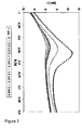
- the measured Faradaic current is determined. This is for example shown in figure 2 , where for a number of potential values E the corresponding Faradaic current values of the potential scan is provided. Preferably, a potential range is selected wherein the differences of Faradaic current values from different stabilizer additive concentrations are biggest. In Figure 2 , this is the case for potential values E in the range of -0.9 to -0.8 V.
- a three electrode set-up with a Ag/AgCl reference electrode, a platinum counter electrode and a copper working electrode and a potentiostat can be used to control the concentration of the stabilizer additive or mixture of stabilizer additives in an electroless metal or metal alloy plating electrolyte.
- the electrolyte and working electrode can be independently agitated or not agitated.
- the inventive method for control of stabilizer additives can be performed for example at the temperature at which the electrolyte is held during metal or metal alloy deposition in production scale.
- the inventive method is applicable in a temperature range of 10 to 100 °C, more preferred between 15 and 60 °C and most preferred between 20 and 40 °C.
- the temperature during steps b. and c. in a series of individual measurements has to be kept constant with a deviation of ⁇ +/- 5 °C, more preferred of ⁇ +/- 2 °C, most preferred ⁇ +/- 1 °C around the selected measurement temperature in order to provide reproducibility of the resulting data.
- the determined value of the Faradaic current of an electroless metal or metal plating electrolyte is optionally compared with the target value of the Faradaic current.
- the target value is equal to the Faradaic current of a freshly prepared electroless metal or metal alloy plating electrolyte determined with the inventive method.
- a freshly prepared electroless metal or metal alloy plating electrolyte contains one or more stabilizer additives in an amount which resembles optimal operating conditions of said electrolyte, e.g., no undesired precipitation of components present in the plating electrolyte, desired plating speed and desired properties of the metal or metal alloy deposit.
- stabilizer additive or mixture of stabilizer additive is added to the tested electroless plating electrolyte.
- the target value should be matched after addition of said stabilizer additive or mixture to a used plating electrolyte.
- the stabilizer additive or mixture of stabilizer additives is added. to the working plating electrolyte in an amount sufficient to reach the target value.
- the inventive method can also be used as an on-line method: at first a sample is taken automatically from the plating electrolyte of a production line for electroless metal deposition. In case of an electroless copper deposition, Cu 2+ , NaOH and formaldehyde concentrations are determined and replenished to set point for this sample (i.e., concentrations for best mode of operation of the plating electrolyte).
- the solution has to be heated or cooled to working electrolyte conditions (e.g., 30 °C).
- working electrolyte conditions e.g. 30 °C.
- a Ag/AgCl reference electrode, a platinum counter electrode and a copper working electrode in a fixed, classical 3-electrode arrangement are applied for this measurement.
- the copper working electrode is a disposable electrode and has to be renewed and pre cleaned before each measurement. The technical application of a disposable copper electrode in an online measurement environment is not described here, since it is a commonly known method.
- Steps a. to d. are done automatically and the collected data are stored.
- the information of the determined Faradaic current value i.e., the stabilizer additive concentration is transferred to the controlling unit of the production line.
- the lacking amount of stabilizer additive solution is calculated and dosed immediately into the production plating electrolyte.
- a three electrode test set-up with a PGSTAT 30 potentiostat (Autolab) and GPES software was used for control of stabilizer additives in electroless copper plating electrolytes in examples 1 to 3. All measurements were done with a Ag/AgCl reference electrode (Metrohm) and a platinum wire as the counter electrode. The electrolyte temperature was held at 30 °C (+/- 2 °C) during all measurements.
- the copper working electrodes were treated with a sodium-persulphate based etch cleaner (150 g/l sodium-persulphate, 5 g/l Cu 2+ and 35 ml/l of 50 wt.-% H 2 SO 4 ) at room temperature for 30 s prior to use.
- the electroless copper electrolyte used for examples 1 to 4 comprised 2 g/l Cu 2+ 10 g/l NaOH 5 g/l formaldehyde (reducing agent) 20 g/l tartrate (complexing agent) Different types and amounts of stabilizer additives were added to said electrolyte during examples 1 to 4.
- the stabilizer additives of an electroless copper electrolyte were monitored.
- a copper plate (10 x 40 mm) was used as the working electrode. Both, working electrode and electrolyte were not agitated during steps a.-c. (table 1).
- a proprietary stabilizer additive mixture (Printoganth ® PV, a product of Atotech Deutschland GmbH), comprising organic and inorganic sulphur compounds and organic nitrogen compounds were added to the electroless copper electrolyte. No cyanide ions were present in the stabilizer additive mixture.
- the analyzing scan (step c. in table 1) is shown as a current vs. potential plot in figure 2 .
- the figure shows the forward scan of the analyze cycle c. (-1000 mV to -600 mV) for different stabilizer additive mixture concentrations in the range of 0 to 3 ml/l. At a potential of -850 mV one can see a depression of the Faradaic current values with an increase of the stabilizer additive mixture concentration.
- the coverage of the working electrode with stabilizer components depends on the concentration of stabilizer components in the plating electrolyte.
- the cyanide ion stabilizer additive of an electroless copper plating electrolyte was monitored.
- a copper plate (10 x 40 mm) was used as the working electrode. Both, working electrode and electrolyte were not agitated during steps a.-c. (table 1).
- the cyanide ion stabilizer additive concentration was varied between 0 and 20 ppm.
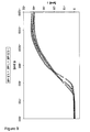
- test protocol used was similar to the one shown in table 1, but instead of measuring the anodic oxidation current of the reducing agent formaldehyde in step c., now the cathodic reduction current of formaldehyde and/or its intermediate species with cyanide ion stabilizer additive was monitored in step c.
- step c. The results of the analyzing scan (step c.) are shown in figure 3 .
- the impact of different cyanide ion stabilizer additive concentrations on the current / potential curves is clearly visible. Therefore, also the cyanide ion stabilizer additive can be monitored using the inventive method.
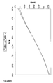
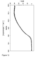
- the cyanide ion concentration in an electroless copper electrolyte described in example 2 was monitored by a potentiometric titration with AgNO 3 using a cyanide ion sensitive electrode (measurement of the potential versus a Ag/AgCl reference electrode).
- This method yielded sufficient precise results for cyanide ion concentrations in the range of 0 to 20 ppm as long as no formaldehyde (i.e., reducing agent) was present in the electroless copper electrolyte ( Figure 5 ).
- hypophosphite electroless copper plating electrolyte was investigated. The test was done with a copper plate working electrode (10 x 40 mm).
- composition of the electroless copper plating electrolyte was: 1 g/I Cu 2+ 0.2 g/l Ni 2+ 9 g/l Tri sodium citrate 15 g/l Boric acid 9 g/l NaOH 27 g/l Sodium hypophosphite (reducing agent) 0.5 to 2.5 ml/l proprietary stabilizer additive mixture (Printoganth ® FF, a product of Atotech GmbH)
- the electro less nickel electrolyte was composed of: 3 g/l Ni 2+ 15 g/l Sodium hypophosphite (reducing agent) 0.5-1.5 ml/l proprietary stabilizer additive mixture (Adhemax ® ALF, a product of Atotech GmbH)
Landscapes
- Chemical & Material Sciences (AREA)
- Chemical Kinetics & Catalysis (AREA)
- Health & Medical Sciences (AREA)
- Life Sciences & Earth Sciences (AREA)
- General Chemical & Material Sciences (AREA)
- Engineering & Computer Science (AREA)
- Materials Engineering (AREA)
- Mechanical Engineering (AREA)
- Metallurgy (AREA)
- Organic Chemistry (AREA)
- Molecular Biology (AREA)
- Electrochemistry (AREA)
- Physics & Mathematics (AREA)
- Analytical Chemistry (AREA)
- Biochemistry (AREA)
- General Health & Medical Sciences (AREA)
- General Physics & Mathematics (AREA)
- Immunology (AREA)
- Pathology (AREA)
- Chemically Coating (AREA)
- Control Of Non-Electrical Variables (AREA)
Priority Applications (8)
| Application Number | Priority Date | Filing Date | Title |
|---|---|---|---|
| AT08075906T ATE546730T1 (de) | 2008-11-26 | 2008-11-26 | Verfahren zur kontrolle von stabilisatoradditiven in elektrolyten zur chemischen metall- und metalllegierungsabscheidung |
| EP08075906A EP2192405B1 (fr) | 2008-11-26 | 2008-11-26 | Procédé de contrôle d'additifs de stabilisateur dans un métal autocatalytique et électrolytes à placage d'alliage métallique |
| TW098139386A TWI441953B (zh) | 2008-11-26 | 2009-11-19 | 無電金屬及金屬合金電鍍電解質中安定添加劑之控制方法 |
| US13/130,315 US8648601B2 (en) | 2008-11-26 | 2009-11-24 | Method for control of stabilizer additives in electroless metal and metal alloy plating electrolytes |
| CN200980148092.5A CN102227628B (zh) | 2008-11-26 | 2009-11-24 | 用于控制无电镀金属和金属合金镀用电解液中稳定添加剂的方法 |
| JP2011537955A JP5335096B2 (ja) | 2008-11-26 | 2009-11-24 | 無電解金属または金属合金めっき電解質中の安定化添加剤の濃度測定方法およびその制御方法 |
| PCT/EP2009/065742 WO2010060906A1 (fr) | 2008-11-26 | 2009-11-24 | Procédé de régulation d'additifs de stabilisation dans des électrolytes de dépôt auto-catalytique de métal et d’alliage métallique |
| KR1020117011902A KR101511408B1 (ko) | 2008-11-26 | 2009-11-24 | 무전해 금속 및 금속 합금 도금 전해질에서의 안정제 첨가물의 제어 방법 |
Applications Claiming Priority (1)
| Application Number | Priority Date | Filing Date | Title |
|---|---|---|---|
| EP08075906A EP2192405B1 (fr) | 2008-11-26 | 2008-11-26 | Procédé de contrôle d'additifs de stabilisateur dans un métal autocatalytique et électrolytes à placage d'alliage métallique |
Publications (2)
| Publication Number | Publication Date |
|---|---|
| EP2192405A1 true EP2192405A1 (fr) | 2010-06-02 |
| EP2192405B1 EP2192405B1 (fr) | 2012-02-22 |
Family
ID=40414573
Family Applications (1)
| Application Number | Title | Priority Date | Filing Date |
|---|---|---|---|
| EP08075906A Not-in-force EP2192405B1 (fr) | 2008-11-26 | 2008-11-26 | Procédé de contrôle d'additifs de stabilisateur dans un métal autocatalytique et électrolytes à placage d'alliage métallique |
Country Status (8)
| Country | Link |
|---|---|
| US (1) | US8648601B2 (fr) |
| EP (1) | EP2192405B1 (fr) |
| JP (1) | JP5335096B2 (fr) |
| KR (1) | KR101511408B1 (fr) |
| CN (1) | CN102227628B (fr) |
| AT (1) | ATE546730T1 (fr) |
| TW (1) | TWI441953B (fr) |
| WO (1) | WO2010060906A1 (fr) |
Families Citing this family (7)
| Publication number | Priority date | Publication date | Assignee | Title |
|---|---|---|---|---|
| JP5443409B2 (ja) * | 2011-02-28 | 2014-03-19 | トヨタ自動車株式会社 | 硫黄系化合物の管理方法及びその管理システム |
| EP3384066B1 (fr) * | 2015-12-03 | 2023-02-08 | Atotech Deutschland GmbH & Co. KG | Procédé de surveillance de la quantité totale de composés contenant du soufre présents dans un bain de placage de métal |
| CN108760821B (zh) * | 2018-06-04 | 2020-09-25 | 电子科技大学 | 一种电镀添加剂的定性和定量分析方法 |
| CN108754467B (zh) * | 2018-06-27 | 2021-01-12 | 深圳市贝加电子材料有限公司 | 钌钯合金化学镀液及其施镀方法和应用 |
| CN113143262B (zh) * | 2021-03-26 | 2023-09-22 | 中国刑事警察学院 | 一种潜手印的显现和固定方法 |
| KR102574198B1 (ko) * | 2021-08-23 | 2023-09-07 | 한국생산기술연구원 | 무전해 도금법을 이용한 혈액 전처리 분리막 일체형 표면증강 라만산란 기판 상 금 박막 도금방법 |
| CN114892235A (zh) * | 2022-04-06 | 2022-08-12 | 北京石油化工学院 | 一种使用电化学手段筛选微弧氧化工艺电解液的方法 |
Citations (4)
| Publication number | Priority date | Publication date | Assignee | Title |
|---|---|---|---|---|
| EP0265901A2 (fr) * | 1986-10-31 | 1988-05-04 | Amp-Akzo Corporation | Contrôle des bains de dépôt chimique |
| US5755954A (en) * | 1996-01-17 | 1998-05-26 | Technic, Inc. | Method of monitoring constituents in electroless plating baths |
| US20030201191A1 (en) * | 2002-04-29 | 2003-10-30 | Applied Materials, Inc. | Electrochemical method for direct organic additives analysis in copper baths |
| US20050183958A1 (en) * | 2002-07-19 | 2005-08-25 | Wikiel Kazimierz J. | Method and apparatus for real time monitoring of industrial electrolytes |
Family Cites Families (10)
| Publication number | Priority date | Publication date | Assignee | Title |
|---|---|---|---|---|
| JPS5345592A (en) * | 1976-10-06 | 1978-04-24 | Toshiba Corp | Concentration measuring method, of non-electrolysis plating liquid |
| US5320724A (en) * | 1992-11-17 | 1994-06-14 | Hughes Aircraft Company | Method of monitoring constituents in plating baths |
| JPH0798296A (ja) * | 1993-09-30 | 1995-04-11 | Hitachi Chem Co Ltd | 無電解銅めっき液中の添加剤の濃度測定法 |
| KR20010014440A (ko) * | 1998-05-01 | 2001-02-26 | 세미툴 인코포레이티드 | 전기도금조 내의 첨가제 농도 측정방법 |
| US7097751B2 (en) * | 2002-08-23 | 2006-08-29 | Kabushiki Kaisha Toshiba | Base sequence detecting electrode, base sequence detecting device and base sequence detecting method |
| US7140229B2 (en) * | 2004-06-29 | 2006-11-28 | Mst Technology Gmbh | Gas-monitoring assembly comprising one or more gas sensors and one or more getters, and method of using same |
| WO2006110437A1 (fr) * | 2005-04-08 | 2006-10-19 | The Trustees Of Columbia University In The City Of New York | Systèmes et procédés de surveillance de bains de placage et d’attaque chimique |
| US8747960B2 (en) * | 2005-08-31 | 2014-06-10 | Lam Research Corporation | Processes and systems for engineering a silicon-type surface for selective metal deposition to form a metal silicide |
| JP4325684B2 (ja) * | 2007-02-20 | 2009-09-02 | 株式会社デンソー | センサ制御装置、及び印加電圧特性の調整方法 |
| MX2010000972A (es) * | 2007-07-26 | 2010-03-01 | Home Diagnostics Inc | Sistema y metodos que determinan concentracion de analito utilizando amperometria resuelta en tiempo. |
-
2008
- 2008-11-26 EP EP08075906A patent/EP2192405B1/fr not_active Not-in-force
- 2008-11-26 AT AT08075906T patent/ATE546730T1/de active
-
2009
- 2009-11-19 TW TW098139386A patent/TWI441953B/zh not_active IP Right Cessation
- 2009-11-24 WO PCT/EP2009/065742 patent/WO2010060906A1/fr not_active Ceased
- 2009-11-24 KR KR1020117011902A patent/KR101511408B1/ko not_active Expired - Fee Related
- 2009-11-24 CN CN200980148092.5A patent/CN102227628B/zh not_active Expired - Fee Related
- 2009-11-24 US US13/130,315 patent/US8648601B2/en not_active Expired - Fee Related
- 2009-11-24 JP JP2011537955A patent/JP5335096B2/ja not_active Expired - Fee Related
Patent Citations (5)
| Publication number | Priority date | Publication date | Assignee | Title |
|---|---|---|---|---|
| EP0265901A2 (fr) * | 1986-10-31 | 1988-05-04 | Amp-Akzo Corporation | Contrôle des bains de dépôt chimique |
| US4814197A (en) | 1986-10-31 | 1989-03-21 | Kollmorgen Corporation | Control of electroless plating baths |
| US5755954A (en) * | 1996-01-17 | 1998-05-26 | Technic, Inc. | Method of monitoring constituents in electroless plating baths |
| US20030201191A1 (en) * | 2002-04-29 | 2003-10-30 | Applied Materials, Inc. | Electrochemical method for direct organic additives analysis in copper baths |
| US20050183958A1 (en) * | 2002-07-19 | 2005-08-25 | Wikiel Kazimierz J. | Method and apparatus for real time monitoring of industrial electrolytes |
Non-Patent Citations (8)
| Title |
|---|
| "ASM Handbook", vol. 5, article "Surface Engineering", pages: 311 - 312 |
| "Electroless Plating: Fundamentals and Applications", AMERICAN ELECTROPLATERS AND SURFACE FINISHERS SOCIETY, pages: 34 - 36 |
| A. M. T. VAN DER PUTTEN; J.-W. G. DE BAKKER, J. ELECTROCHEM. SOC., vol. 140, no. 8, 1993, pages 2229 - 2235 |
| J. ELECTROCHEM. SOC., vol. 127, 1980, pages 365 - 369 |
| M. L. ROTHSTEIN, METAL FINISHING, vol. 35-39, October 1984 (1984-10-01) |
| SATO; SUZUKI, J. ELECTROCHEM. SOC., vol. 135, 1988, pages 1645 - 1650 |
| SURFACE AND COATINGS TECHNOLOGY, vol. 28, 1996, pages 151 - 160 |
| VITKAVAGE; PAUNOVIC, ANNUAL TECHNICAL CONFERENCE PROCEEDINGS-AMERICAN ELECTROPLATERS' SOCIETY, 1992, pages 1 - 26 |
Also Published As
| Publication number | Publication date |
|---|---|
| ATE546730T1 (de) | 2012-03-15 |
| CN102227628B (zh) | 2015-01-28 |
| JP5335096B2 (ja) | 2013-11-06 |
| KR101511408B1 (ko) | 2015-04-15 |
| US20110221445A1 (en) | 2011-09-15 |
| US8648601B2 (en) | 2014-02-11 |
| TWI441953B (zh) | 2014-06-21 |
| KR20110088531A (ko) | 2011-08-03 |
| CN102227628A (zh) | 2011-10-26 |
| JP2012510068A (ja) | 2012-04-26 |
| EP2192405B1 (fr) | 2012-02-22 |
| WO2010060906A1 (fr) | 2010-06-03 |
| TW201026905A (en) | 2010-07-16 |
Similar Documents
| Publication | Publication Date | Title |
|---|---|---|
| EP2192405B1 (fr) | Procédé de contrôle d'additifs de stabilisateur dans un métal autocatalytique et électrolytes à placage d'alliage métallique | |
| EP1203950B1 (fr) | Analyse de bains de placage | |
| JP4427452B2 (ja) | 無電解めっき浴中の還元剤の濃度の計測 | |
| EP2937686B1 (fr) | Analyse d'un bain galvanoplastique | |
| JP6903112B2 (ja) | 金属めっき浴中の硫黄含有化合物の合計量のモニタリング方法 | |
| TWI275790B (en) | Analysis method | |
| JP2004323971A (ja) | 改良された浴分析 | |
| Zen et al. | Electrochemical impedance study and sensitive voltammetric determination of Pb (II) at electrochemically activated glassy carbon electrodes | |
| Sargent et al. | Probing the mechanism of electroless gold plating using an EQCM: II. Effect of bath additives on interfacial plating processes | |
| EP0747944B1 (fr) | Evaluation potentiométrique de l'oxidation et de la porosité de revêtement de substrat | |
| CN110632134A (zh) | 一种热轧酸洗钢板表面氯离子含量的快速检测方法 | |
| Tuna et al. | EQCM and EIS characterization of electrochemical deposition of tin from aqueous solution containing pyrophosphate | |
| US7141156B2 (en) | One-point recalibration method for reducing error in concentration measurements for an electrolytic solution | |
| Karthikeyan et al. | Impedance measurements for electroless nickel plating process | |
| de Souzaa et al. | Indirect detection of corrosion by quantifying the Fe (II)-TEA complex | |
| WO2023167798A1 (fr) | Analyse électrochimique de dépolarisants métalliques dans l'électrodéposition d'or | |
| CN121186157A (zh) | 一种利用磁流体复合材料丝网印刷电极检测多种重金属离子的方法 |
Legal Events
| Date | Code | Title | Description |
|---|---|---|---|
| PUAI | Public reference made under article 153(3) epc to a published international application that has entered the european phase |
Free format text: ORIGINAL CODE: 0009012 |
|
| AK | Designated contracting states |
Kind code of ref document: A1 Designated state(s): AT BE BG CH CY CZ DE DK EE ES FI FR GB GR HR HU IE IS IT LI LT LU LV MC MT NL NO PL PT RO SE SI SK TR |
|
| AX | Request for extension of the european patent |
Extension state: AL BA MK RS |
|
| 17P | Request for examination filed |
Effective date: 20101007 |
|
| AKX | Designation fees paid |
Designated state(s): AT BE BG CH CY CZ DE DK EE ES FI FR GB GR HR HU IE IS IT LI LT LU LV MC MT NL NO PL PT RO SE SI SK TR |
|
| 17Q | First examination report despatched |
Effective date: 20110317 |
|
| GRAP | Despatch of communication of intention to grant a patent |
Free format text: ORIGINAL CODE: EPIDOSNIGR1 |
|
| GRAS | Grant fee paid |
Free format text: ORIGINAL CODE: EPIDOSNIGR3 |
|
| GRAA | (expected) grant |
Free format text: ORIGINAL CODE: 0009210 |
|
| AK | Designated contracting states |
Kind code of ref document: B1 Designated state(s): AT BE BG CH CY CZ DE DK EE ES FI FR GB GR HR HU IE IS IT LI LT LU LV MC MT NL NO PL PT RO SE SI SK TR |
|
| REG | Reference to a national code |
Ref country code: GB Ref legal event code: FG4D |
|
| REG | Reference to a national code |
Ref country code: CH Ref legal event code: EP |
|
| REG | Reference to a national code |
Ref country code: AT Ref legal event code: REF Ref document number: 546730 Country of ref document: AT Kind code of ref document: T Effective date: 20120315 |
|
| REG | Reference to a national code |
Ref country code: IE Ref legal event code: FG4D |
|
| REG | Reference to a national code |
Ref country code: DE Ref legal event code: R096 Ref document number: 602008013529 Country of ref document: DE Effective date: 20120419 |
|
| RAP2 | Party data changed (patent owner data changed or rights of a patent transferred) |
Owner name: ATOTECH DEUTSCHLAND GMBH |
|
| REG | Reference to a national code |
Ref country code: NL Ref legal event code: VDEP Effective date: 20120222 |
|
| LTIE | Lt: invalidation of european patent or patent extension |
Effective date: 20120222 |
|
| PG25 | Lapsed in a contracting state [announced via postgrant information from national office to epo] |
Ref country code: IS Free format text: LAPSE BECAUSE OF FAILURE TO SUBMIT A TRANSLATION OF THE DESCRIPTION OR TO PAY THE FEE WITHIN THE PRESCRIBED TIME-LIMIT Effective date: 20120622 Ref country code: LT Free format text: LAPSE BECAUSE OF FAILURE TO SUBMIT A TRANSLATION OF THE DESCRIPTION OR TO PAY THE FEE WITHIN THE PRESCRIBED TIME-LIMIT Effective date: 20120222 Ref country code: NO Free format text: LAPSE BECAUSE OF FAILURE TO SUBMIT A TRANSLATION OF THE DESCRIPTION OR TO PAY THE FEE WITHIN THE PRESCRIBED TIME-LIMIT Effective date: 20120522 Ref country code: NL Free format text: LAPSE BECAUSE OF FAILURE TO SUBMIT A TRANSLATION OF THE DESCRIPTION OR TO PAY THE FEE WITHIN THE PRESCRIBED TIME-LIMIT Effective date: 20120222 Ref country code: HR Free format text: LAPSE BECAUSE OF FAILURE TO SUBMIT A TRANSLATION OF THE DESCRIPTION OR TO PAY THE FEE WITHIN THE PRESCRIBED TIME-LIMIT Effective date: 20120222 |
|
| PG25 | Lapsed in a contracting state [announced via postgrant information from national office to epo] |
Ref country code: PT Free format text: LAPSE BECAUSE OF FAILURE TO SUBMIT A TRANSLATION OF THE DESCRIPTION OR TO PAY THE FEE WITHIN THE PRESCRIBED TIME-LIMIT Effective date: 20120622 Ref country code: FI Free format text: LAPSE BECAUSE OF FAILURE TO SUBMIT A TRANSLATION OF THE DESCRIPTION OR TO PAY THE FEE WITHIN THE PRESCRIBED TIME-LIMIT Effective date: 20120222 Ref country code: GR Free format text: LAPSE BECAUSE OF FAILURE TO SUBMIT A TRANSLATION OF THE DESCRIPTION OR TO PAY THE FEE WITHIN THE PRESCRIBED TIME-LIMIT Effective date: 20120523 Ref country code: LV Free format text: LAPSE BECAUSE OF FAILURE TO SUBMIT A TRANSLATION OF THE DESCRIPTION OR TO PAY THE FEE WITHIN THE PRESCRIBED TIME-LIMIT Effective date: 20120222 Ref country code: BE Free format text: LAPSE BECAUSE OF FAILURE TO SUBMIT A TRANSLATION OF THE DESCRIPTION OR TO PAY THE FEE WITHIN THE PRESCRIBED TIME-LIMIT Effective date: 20120222 |
|
| PG25 | Lapsed in a contracting state [announced via postgrant information from national office to epo] |
Ref country code: CY Free format text: LAPSE BECAUSE OF FAILURE TO SUBMIT A TRANSLATION OF THE DESCRIPTION OR TO PAY THE FEE WITHIN THE PRESCRIBED TIME-LIMIT Effective date: 20120222 |
|
| PG25 | Lapsed in a contracting state [announced via postgrant information from national office to epo] |
Ref country code: RO Free format text: LAPSE BECAUSE OF FAILURE TO SUBMIT A TRANSLATION OF THE DESCRIPTION OR TO PAY THE FEE WITHIN THE PRESCRIBED TIME-LIMIT Effective date: 20120222 Ref country code: SI Free format text: LAPSE BECAUSE OF FAILURE TO SUBMIT A TRANSLATION OF THE DESCRIPTION OR TO PAY THE FEE WITHIN THE PRESCRIBED TIME-LIMIT Effective date: 20120222 Ref country code: PL Free format text: LAPSE BECAUSE OF FAILURE TO SUBMIT A TRANSLATION OF THE DESCRIPTION OR TO PAY THE FEE WITHIN THE PRESCRIBED TIME-LIMIT Effective date: 20120222 Ref country code: SE Free format text: LAPSE BECAUSE OF FAILURE TO SUBMIT A TRANSLATION OF THE DESCRIPTION OR TO PAY THE FEE WITHIN THE PRESCRIBED TIME-LIMIT Effective date: 20120222 Ref country code: DK Free format text: LAPSE BECAUSE OF FAILURE TO SUBMIT A TRANSLATION OF THE DESCRIPTION OR TO PAY THE FEE WITHIN THE PRESCRIBED TIME-LIMIT Effective date: 20120222 Ref country code: EE Free format text: LAPSE BECAUSE OF FAILURE TO SUBMIT A TRANSLATION OF THE DESCRIPTION OR TO PAY THE FEE WITHIN THE PRESCRIBED TIME-LIMIT Effective date: 20120222 Ref country code: CZ Free format text: LAPSE BECAUSE OF FAILURE TO SUBMIT A TRANSLATION OF THE DESCRIPTION OR TO PAY THE FEE WITHIN THE PRESCRIBED TIME-LIMIT Effective date: 20120222 |
|
| PG25 | Lapsed in a contracting state [announced via postgrant information from national office to epo] |
Ref country code: SK Free format text: LAPSE BECAUSE OF FAILURE TO SUBMIT A TRANSLATION OF THE DESCRIPTION OR TO PAY THE FEE WITHIN THE PRESCRIBED TIME-LIMIT Effective date: 20120222 |
|
| PLBE | No opposition filed within time limit |
Free format text: ORIGINAL CODE: 0009261 |
|
| STAA | Information on the status of an ep patent application or granted ep patent |
Free format text: STATUS: NO OPPOSITION FILED WITHIN TIME LIMIT |
|
| 26N | No opposition filed |
Effective date: 20121123 |
|
| REG | Reference to a national code |
Ref country code: DE Ref legal event code: R097 Ref document number: 602008013529 Country of ref document: DE Effective date: 20121123 |
|
| REG | Reference to a national code |
Ref country code: CH Ref legal event code: PL |
|
| GBPC | Gb: european patent ceased through non-payment of renewal fee |
Effective date: 20121126 |
|
| PG25 | Lapsed in a contracting state [announced via postgrant information from national office to epo] |
Ref country code: LI Free format text: LAPSE BECAUSE OF NON-PAYMENT OF DUE FEES Effective date: 20121130 Ref country code: BG Free format text: LAPSE BECAUSE OF FAILURE TO SUBMIT A TRANSLATION OF THE DESCRIPTION OR TO PAY THE FEE WITHIN THE PRESCRIBED TIME-LIMIT Effective date: 20120522 Ref country code: CH Free format text: LAPSE BECAUSE OF NON-PAYMENT OF DUE FEES Effective date: 20121130 |
|
| REG | Reference to a national code |
Ref country code: IE Ref legal event code: MM4A |
|
| PG25 | Lapsed in a contracting state [announced via postgrant information from national office to epo] |
Ref country code: IE Free format text: LAPSE BECAUSE OF NON-PAYMENT OF DUE FEES Effective date: 20121126 Ref country code: ES Free format text: LAPSE BECAUSE OF FAILURE TO SUBMIT A TRANSLATION OF THE DESCRIPTION OR TO PAY THE FEE WITHIN THE PRESCRIBED TIME-LIMIT Effective date: 20120602 |
|
| PG25 | Lapsed in a contracting state [announced via postgrant information from national office to epo] |
Ref country code: GB Free format text: LAPSE BECAUSE OF NON-PAYMENT OF DUE FEES Effective date: 20121126 Ref country code: MT Free format text: LAPSE BECAUSE OF FAILURE TO SUBMIT A TRANSLATION OF THE DESCRIPTION OR TO PAY THE FEE WITHIN THE PRESCRIBED TIME-LIMIT Effective date: 20120222 |
|
| PG25 | Lapsed in a contracting state [announced via postgrant information from national office to epo] |
Ref country code: MC Free format text: LAPSE BECAUSE OF NON-PAYMENT OF DUE FEES Effective date: 20121130 Ref country code: TR Free format text: LAPSE BECAUSE OF FAILURE TO SUBMIT A TRANSLATION OF THE DESCRIPTION OR TO PAY THE FEE WITHIN THE PRESCRIBED TIME-LIMIT Effective date: 20120222 |
|
| PG25 | Lapsed in a contracting state [announced via postgrant information from national office to epo] |
Ref country code: LU Free format text: LAPSE BECAUSE OF NON-PAYMENT OF DUE FEES Effective date: 20121126 |
|
| PG25 | Lapsed in a contracting state [announced via postgrant information from national office to epo] |
Ref country code: HU Free format text: LAPSE BECAUSE OF FAILURE TO SUBMIT A TRANSLATION OF THE DESCRIPTION OR TO PAY THE FEE WITHIN THE PRESCRIBED TIME-LIMIT Effective date: 20081126 |
|
| REG | Reference to a national code |
Ref country code: FR Ref legal event code: PLFP Year of fee payment: 8 |
|
| REG | Reference to a national code |
Ref country code: FR Ref legal event code: PLFP Year of fee payment: 9 |
|
| REG | Reference to a national code |
Ref country code: FR Ref legal event code: PLFP Year of fee payment: 10 |
|
| PGFP | Annual fee paid to national office [announced via postgrant information from national office to epo] |
Ref country code: DE Payment date: 20181120 Year of fee payment: 11 Ref country code: AT Payment date: 20181121 Year of fee payment: 11 |
|
| PGFP | Annual fee paid to national office [announced via postgrant information from national office to epo] |
Ref country code: IT Payment date: 20181126 Year of fee payment: 11 Ref country code: FR Payment date: 20181123 Year of fee payment: 11 |
|
| REG | Reference to a national code |
Ref country code: DE Ref legal event code: R119 Ref document number: 602008013529 Country of ref document: DE |
|
| REG | Reference to a national code |
Ref country code: AT Ref legal event code: MM01 Ref document number: 546730 Country of ref document: AT Kind code of ref document: T Effective date: 20191126 |
|
| PG25 | Lapsed in a contracting state [announced via postgrant information from national office to epo] |
Ref country code: FR Free format text: LAPSE BECAUSE OF NON-PAYMENT OF DUE FEES Effective date: 20191130 Ref country code: IT Free format text: LAPSE BECAUSE OF NON-PAYMENT OF DUE FEES Effective date: 20191126 Ref country code: DE Free format text: LAPSE BECAUSE OF NON-PAYMENT OF DUE FEES Effective date: 20200603 |
|
| PG25 | Lapsed in a contracting state [announced via postgrant information from national office to epo] |
Ref country code: AT Free format text: LAPSE BECAUSE OF NON-PAYMENT OF DUE FEES Effective date: 20191126 |