EP0265901A2 - Contrôle des bains de dépôt chimique - Google Patents
Contrôle des bains de dépôt chimique Download PDFInfo
- Publication number
- EP0265901A2 EP0265901A2 EP87115717A EP87115717A EP0265901A2 EP 0265901 A2 EP0265901 A2 EP 0265901A2 EP 87115717 A EP87115717 A EP 87115717A EP 87115717 A EP87115717 A EP 87115717A EP 0265901 A2 EP0265901 A2 EP 0265901A2
- Authority
- EP
- European Patent Office
- Prior art keywords
- copper
- plating solution
- concentration
- electrodes
- potential
- Prior art date
- Legal status (The legal status is an assumption and is not a legal conclusion. Google has not performed a legal analysis and makes no representation as to the accuracy of the status listed.)
- Granted
Links
- 238000007772 electroless plating Methods 0.000 title claims abstract description 21
- 239000000243 solution Substances 0.000 claims abstract description 66
- 238000000034 method Methods 0.000 claims abstract description 62
- 238000004458 analytical method Methods 0.000 claims abstract description 13
- 239000000470 constituent Substances 0.000 claims abstract description 12
- WSFSSNUMVMOOMR-UHFFFAOYSA-N Formaldehyde Chemical group O=C WSFSSNUMVMOOMR-UHFFFAOYSA-N 0.000 claims description 112
- RYGMFSIKBFXOCR-UHFFFAOYSA-N Copper Chemical compound [Cu] RYGMFSIKBFXOCR-UHFFFAOYSA-N 0.000 claims description 103
- 229910052802 copper Inorganic materials 0.000 claims description 101
- 239000010949 copper Substances 0.000 claims description 101
- 238000007747 plating Methods 0.000 claims description 87
- 229960004279 formaldehyde Drugs 0.000 claims description 35
- 235000019256 formaldehyde Nutrition 0.000 claims description 35
- 239000000203 mixture Substances 0.000 claims description 35
- 239000003638 chemical reducing agent Substances 0.000 claims description 33
- 238000006243 chemical reaction Methods 0.000 claims description 32
- 238000012360 testing method Methods 0.000 claims description 30
- 238000005259 measurement Methods 0.000 claims description 27
- 238000007792 addition Methods 0.000 claims description 21
- 150000001455 metallic ions Chemical class 0.000 claims description 19
- 239000003381 stabilizer Substances 0.000 claims description 18
- 238000010349 cathodic reaction Methods 0.000 claims description 16
- WSFSSNUMVMOOMR-NJFSPNSNSA-N methanone Chemical group O=[14CH2] WSFSSNUMVMOOMR-NJFSPNSNSA-N 0.000 claims description 10
- 229910052751 metal Inorganic materials 0.000 claims description 9
- 239000002184 metal Substances 0.000 claims description 9
- JPVYNHNXODAKFH-UHFFFAOYSA-N Cu2+ Chemical compound [Cu+2] JPVYNHNXODAKFH-UHFFFAOYSA-N 0.000 claims description 8
- 230000001276 controlling effect Effects 0.000 claims description 8
- 229910001431 copper ion Inorganic materials 0.000 claims description 8
- 239000000126 substance Substances 0.000 claims description 8
- 229910021645 metal ion Inorganic materials 0.000 claims description 6
- ARUVKPQLZAKDPS-UHFFFAOYSA-L copper(II) sulfate Chemical compound [Cu+2].[O-][S+2]([O-])([O-])[O-] ARUVKPQLZAKDPS-UHFFFAOYSA-L 0.000 claims description 5
- XLYOFNOQVPJJNP-UHFFFAOYSA-M hydroxide Chemical compound [OH-] XLYOFNOQVPJJNP-UHFFFAOYSA-M 0.000 claims description 5
- 238000012544 monitoring process Methods 0.000 claims description 4
- UORVGPXVDQYIDP-UHFFFAOYSA-N borane Chemical class B UORVGPXVDQYIDP-UHFFFAOYSA-N 0.000 claims description 3
- 239000003795 chemical substances by application Substances 0.000 claims description 3
- 238000000840 electrochemical analysis Methods 0.000 claims description 3
- VEQPNABPJHWNSG-UHFFFAOYSA-N Nickel(2+) Chemical compound [Ni+2] VEQPNABPJHWNSG-UHFFFAOYSA-N 0.000 claims description 2
- 230000003247 decreasing effect Effects 0.000 claims description 2
- 229910001453 nickel ion Inorganic materials 0.000 claims description 2
- ACVYVLVWPXVTIT-UHFFFAOYSA-M phosphinate Chemical group [O-][PH2]=O ACVYVLVWPXVTIT-UHFFFAOYSA-M 0.000 claims description 2
- 238000003487 electrochemical reaction Methods 0.000 claims 4
- 239000002344 surface layer Substances 0.000 claims 3
- 238000013459 approach Methods 0.000 claims 1
- 230000000737 periodic effect Effects 0.000 claims 1
- 239000012224 working solution Substances 0.000 abstract 1
- 239000000523 sample Substances 0.000 description 30
- 230000008569 process Effects 0.000 description 16
- 239000004020 conductor Substances 0.000 description 12
- HEMHJVSKTPXQMS-UHFFFAOYSA-M sodium hydroxide Inorganic materials [OH-].[Na+] HEMHJVSKTPXQMS-UHFFFAOYSA-M 0.000 description 11
- 230000005484 gravity Effects 0.000 description 10
- 230000000875 corresponding effect Effects 0.000 description 8
- BASFCYQUMIYNBI-UHFFFAOYSA-N platinum Chemical compound [Pt] BASFCYQUMIYNBI-UHFFFAOYSA-N 0.000 description 8
- XFXPMWWXUTWYJX-UHFFFAOYSA-N Cyanide Chemical compound N#[C-] XFXPMWWXUTWYJX-UHFFFAOYSA-N 0.000 description 7
- 238000012625 in-situ measurement Methods 0.000 description 7
- 230000004044 response Effects 0.000 description 7
- 238000000151 deposition Methods 0.000 description 6
- 238000010586 diagram Methods 0.000 description 6
- 238000011065 in-situ storage Methods 0.000 description 6
- 230000008021 deposition Effects 0.000 description 5
- 238000009472 formulation Methods 0.000 description 5
- 238000007254 oxidation reaction Methods 0.000 description 5
- XLYOFNOQVPJJNP-UHFFFAOYSA-N water Substances O XLYOFNOQVPJJNP-UHFFFAOYSA-N 0.000 description 5
- 230000009471 action Effects 0.000 description 4
- 239000006227 byproduct Substances 0.000 description 4
- 239000000306 component Substances 0.000 description 4
- 229910000365 copper sulfate Inorganic materials 0.000 description 4
- ZOMNIUBKTOKEHS-UHFFFAOYSA-L dimercury dichloride Chemical compound Cl[Hg][Hg]Cl ZOMNIUBKTOKEHS-UHFFFAOYSA-L 0.000 description 4
- 239000000835 fiber Substances 0.000 description 4
- 229910052697 platinum Inorganic materials 0.000 description 4
- KWYUFKZDYYNOTN-UHFFFAOYSA-M Potassium hydroxide Chemical compound [OH-].[K+] KWYUFKZDYYNOTN-UHFFFAOYSA-M 0.000 description 3
- 229910021607 Silver chloride Inorganic materials 0.000 description 3
- 230000003197 catalytic effect Effects 0.000 description 3
- 230000008859 change Effects 0.000 description 3
- KXZJHVJKXJLBKO-UHFFFAOYSA-N chembl1408157 Chemical compound N=1C2=CC=CC=C2C(C(=O)O)=CC=1C1=CC=C(O)C=C1 KXZJHVJKXJLBKO-UHFFFAOYSA-N 0.000 description 3
- 239000003153 chemical reaction reagent Substances 0.000 description 3
- 239000011248 coating agent Substances 0.000 description 3
- 238000000576 coating method Methods 0.000 description 3
- 238000004590 computer program Methods 0.000 description 3
- 239000013078 crystal Substances 0.000 description 3
- 238000007405 data analysis Methods 0.000 description 3
- 230000007547 defect Effects 0.000 description 3
- 230000005684 electric field Effects 0.000 description 3
- 230000003647 oxidation Effects 0.000 description 3
- QHGVXILFMXYDRS-UHFFFAOYSA-N pyraclofos Chemical compound C1=C(OP(=O)(OCC)SCCC)C=NN1C1=CC=C(Cl)C=C1 QHGVXILFMXYDRS-UHFFFAOYSA-N 0.000 description 3
- HKZLPVFGJNLROG-UHFFFAOYSA-M silver monochloride Chemical compound [Cl-].[Ag+] HKZLPVFGJNLROG-UHFFFAOYSA-M 0.000 description 3
- 229910052720 vanadium Inorganic materials 0.000 description 3
- DETXZQGDWUJKMO-UHFFFAOYSA-N 2-hydroxymethanesulfonic acid Chemical compound OCS(O)(=O)=O DETXZQGDWUJKMO-UHFFFAOYSA-N 0.000 description 2
- PXHVJJICTQNCMI-UHFFFAOYSA-N Nickel Chemical compound [Ni] PXHVJJICTQNCMI-UHFFFAOYSA-N 0.000 description 2
- 239000008139 complexing agent Substances 0.000 description 2
- 238000012937 correction Methods 0.000 description 2
- 238000009826 distribution Methods 0.000 description 2
- GNTDGMZSJNCJKK-UHFFFAOYSA-N divanadium pentaoxide Chemical compound O=[V](=O)O[V](=O)=O GNTDGMZSJNCJKK-UHFFFAOYSA-N 0.000 description 2
- -1 e.g. Substances 0.000 description 2
- 238000011067 equilibration Methods 0.000 description 2
- 238000001914 filtration Methods 0.000 description 2
- 238000010438 heat treatment Methods 0.000 description 2
- 125000002887 hydroxy group Chemical group [H]O* 0.000 description 2
- 238000003780 insertion Methods 0.000 description 2
- 230000037431 insertion Effects 0.000 description 2
- 150000002500 ions Chemical class 0.000 description 2
- QSHDDOUJBYECFT-UHFFFAOYSA-N mercury Chemical compound [Hg] QSHDDOUJBYECFT-UHFFFAOYSA-N 0.000 description 2
- 229910052753 mercury Inorganic materials 0.000 description 2
- 238000002156 mixing Methods 0.000 description 2
- 238000001139 pH measurement Methods 0.000 description 2
- 238000002360 preparation method Methods 0.000 description 2
- 238000004886 process control Methods 0.000 description 2
- 230000001172 regenerating effect Effects 0.000 description 2
- 230000008929 regeneration Effects 0.000 description 2
- 238000011069 regeneration method Methods 0.000 description 2
- 230000003252 repetitive effect Effects 0.000 description 2
- 238000005070 sampling Methods 0.000 description 2
- 229910052709 silver Inorganic materials 0.000 description 2
- 239000004332 silver Substances 0.000 description 2
- GEHJYWRUCIMESM-UHFFFAOYSA-L sodium sulfite Chemical compound [Na+].[Na+].[O-]S([O-])=O GEHJYWRUCIMESM-UHFFFAOYSA-L 0.000 description 2
- 229910000679 solder Inorganic materials 0.000 description 2
- BGJSXRVXTHVRSN-UHFFFAOYSA-N 1,3,5-trioxane Chemical compound C1OCOCO1 BGJSXRVXTHVRSN-UHFFFAOYSA-N 0.000 description 1
- 102100032392 Circadian-associated transcriptional repressor Human genes 0.000 description 1
- 101710130150 Circadian-associated transcriptional repressor Proteins 0.000 description 1
- KCXVZYZYPLLWCC-UHFFFAOYSA-N EDTA Chemical compound OC(=O)CN(CC(O)=O)CCN(CC(O)=O)CC(O)=O KCXVZYZYPLLWCC-UHFFFAOYSA-N 0.000 description 1
- DGAQECJNVWCQMB-PUAWFVPOSA-M Ilexoside XXIX Chemical compound C[C@@H]1CC[C@@]2(CC[C@@]3(C(=CC[C@H]4[C@]3(CC[C@@H]5[C@@]4(CC[C@@H](C5(C)C)OS(=O)(=O)[O-])C)C)[C@@H]2[C@]1(C)O)C)C(=O)O[C@H]6[C@@H]([C@H]([C@@H]([C@H](O6)CO)O)O)O.[Na+] DGAQECJNVWCQMB-PUAWFVPOSA-M 0.000 description 1
- 229930040373 Paraformaldehyde Natural products 0.000 description 1
- LSNNMFCWUKXFEE-UHFFFAOYSA-N Sulfurous acid Chemical compound OS(O)=O LSNNMFCWUKXFEE-UHFFFAOYSA-N 0.000 description 1
- 238000010521 absorption reaction Methods 0.000 description 1
- 229910052783 alkali metal Inorganic materials 0.000 description 1
- 150000001340 alkali metals Chemical class 0.000 description 1
- 239000012670 alkaline solution Substances 0.000 description 1
- 230000015572 biosynthetic process Effects 0.000 description 1
- 229910000085 borane Inorganic materials 0.000 description 1
- 229940075397 calomel Drugs 0.000 description 1
- 238000004140 cleaning Methods 0.000 description 1
- 238000004737 colorimetric analysis Methods 0.000 description 1
- 150000001875 compounds Chemical class 0.000 description 1
- 239000000356 contaminant Substances 0.000 description 1
- 238000011109 contamination Methods 0.000 description 1
- 238000001816 cooling Methods 0.000 description 1
- 238000007883 cyanide addition reaction Methods 0.000 description 1
- 125000004122 cyclic group Chemical group 0.000 description 1
- 230000006378 damage Effects 0.000 description 1
- 230000007423 decrease Effects 0.000 description 1
- 238000013461 design Methods 0.000 description 1
- 238000010790 dilution Methods 0.000 description 1
- 239000012895 dilution Substances 0.000 description 1
- HVFFICXFJBAZMU-UHFFFAOYSA-N ethoxy dihydrogen phosphate Chemical compound CCOOP(O)(O)=O HVFFICXFJBAZMU-UHFFFAOYSA-N 0.000 description 1
- 230000031700 light absorption Effects 0.000 description 1
- 238000011068 loading method Methods 0.000 description 1
- 238000004519 manufacturing process Methods 0.000 description 1
- 150000002739 metals Chemical class 0.000 description 1
- 238000012986 modification Methods 0.000 description 1
- 230000004048 modification Effects 0.000 description 1
- 229910052759 nickel Inorganic materials 0.000 description 1
- 230000003287 optical effect Effects 0.000 description 1
- 238000004806 packaging method and process Methods 0.000 description 1
- 230000010287 polarization Effects 0.000 description 1
- 238000003969 polarography Methods 0.000 description 1
- 230000003334 potential effect Effects 0.000 description 1
- 238000004313 potentiometry Methods 0.000 description 1
- 239000000376 reactant Substances 0.000 description 1
- 230000035939 shock Effects 0.000 description 1
- MNWBNISUBARLIT-UHFFFAOYSA-N sodium cyanide Chemical compound [Na+].N#[C-] MNWBNISUBARLIT-UHFFFAOYSA-N 0.000 description 1
- NQXGLOVMOABDLI-UHFFFAOYSA-N sodium oxido(oxo)phosphanium Chemical compound [Na+].[O-][PH+]=O NQXGLOVMOABDLI-UHFFFAOYSA-N 0.000 description 1
- 235000010265 sodium sulphite Nutrition 0.000 description 1
- 230000002311 subsequent effect Effects 0.000 description 1
- 239000000758 substrate Substances 0.000 description 1
- 239000003115 supporting electrolyte Substances 0.000 description 1
- 239000004094 surface-active agent Substances 0.000 description 1
- 238000010408 sweeping Methods 0.000 description 1
- 239000012085 test solution Substances 0.000 description 1
- 238000004448 titration Methods 0.000 description 1
- LEONUFNNVUYDNQ-UHFFFAOYSA-N vanadium atom Chemical compound [V] LEONUFNNVUYDNQ-UHFFFAOYSA-N 0.000 description 1
- 238000011179 visual inspection Methods 0.000 description 1
- 238000004832 voltammetry Methods 0.000 description 1
Images




Classifications
-
- C—CHEMISTRY; METALLURGY
- C23—COATING METALLIC MATERIAL; COATING MATERIAL WITH METALLIC MATERIAL; CHEMICAL SURFACE TREATMENT; DIFFUSION TREATMENT OF METALLIC MATERIAL; COATING BY VACUUM EVAPORATION, BY SPUTTERING, BY ION IMPLANTATION OR BY CHEMICAL VAPOUR DEPOSITION, IN GENERAL; INHIBITING CORROSION OF METALLIC MATERIAL OR INCRUSTATION IN GENERAL
- C23C—COATING METALLIC MATERIAL; COATING MATERIAL WITH METALLIC MATERIAL; SURFACE TREATMENT OF METALLIC MATERIAL BY DIFFUSION INTO THE SURFACE, BY CHEMICAL CONVERSION OR SUBSTITUTION; COATING BY VACUUM EVAPORATION, BY SPUTTERING, BY ION IMPLANTATION OR BY CHEMICAL VAPOUR DEPOSITION, IN GENERAL
- C23C18/00—Chemical coating by decomposition of either liquid compounds or solutions of the coating forming compounds, without leaving reaction products of surface material in the coating; Contact plating
- C23C18/16—Chemical coating by decomposition of either liquid compounds or solutions of the coating forming compounds, without leaving reaction products of surface material in the coating; Contact plating by reduction or substitution, e.g. electroless plating
- C23C18/31—Coating with metals
- C23C18/32—Coating with nickel, cobalt or mixtures thereof with phosphorus or boron
- C23C18/34—Coating with nickel, cobalt or mixtures thereof with phosphorus or boron using reducing agents
-
- C—CHEMISTRY; METALLURGY
- C23—COATING METALLIC MATERIAL; COATING MATERIAL WITH METALLIC MATERIAL; CHEMICAL SURFACE TREATMENT; DIFFUSION TREATMENT OF METALLIC MATERIAL; COATING BY VACUUM EVAPORATION, BY SPUTTERING, BY ION IMPLANTATION OR BY CHEMICAL VAPOUR DEPOSITION, IN GENERAL; INHIBITING CORROSION OF METALLIC MATERIAL OR INCRUSTATION IN GENERAL
- C23C—COATING METALLIC MATERIAL; COATING MATERIAL WITH METALLIC MATERIAL; SURFACE TREATMENT OF METALLIC MATERIAL BY DIFFUSION INTO THE SURFACE, BY CHEMICAL CONVERSION OR SUBSTITUTION; COATING BY VACUUM EVAPORATION, BY SPUTTERING, BY ION IMPLANTATION OR BY CHEMICAL VAPOUR DEPOSITION, IN GENERAL
- C23C18/00—Chemical coating by decomposition of either liquid compounds or solutions of the coating forming compounds, without leaving reaction products of surface material in the coating; Contact plating
- C23C18/16—Chemical coating by decomposition of either liquid compounds or solutions of the coating forming compounds, without leaving reaction products of surface material in the coating; Contact plating by reduction or substitution, e.g. electroless plating
- C23C18/1601—Process or apparatus
- C23C18/1633—Process of electroless plating
- C23C18/1675—Process conditions
-
- C—CHEMISTRY; METALLURGY
- C23—COATING METALLIC MATERIAL; COATING MATERIAL WITH METALLIC MATERIAL; CHEMICAL SURFACE TREATMENT; DIFFUSION TREATMENT OF METALLIC MATERIAL; COATING BY VACUUM EVAPORATION, BY SPUTTERING, BY ION IMPLANTATION OR BY CHEMICAL VAPOUR DEPOSITION, IN GENERAL; INHIBITING CORROSION OF METALLIC MATERIAL OR INCRUSTATION IN GENERAL
- C23C—COATING METALLIC MATERIAL; COATING MATERIAL WITH METALLIC MATERIAL; SURFACE TREATMENT OF METALLIC MATERIAL BY DIFFUSION INTO THE SURFACE, BY CHEMICAL CONVERSION OR SUBSTITUTION; COATING BY VACUUM EVAPORATION, BY SPUTTERING, BY ION IMPLANTATION OR BY CHEMICAL VAPOUR DEPOSITION, IN GENERAL
- C23C18/00—Chemical coating by decomposition of either liquid compounds or solutions of the coating forming compounds, without leaving reaction products of surface material in the coating; Contact plating
- C23C18/16—Chemical coating by decomposition of either liquid compounds or solutions of the coating forming compounds, without leaving reaction products of surface material in the coating; Contact plating by reduction or substitution, e.g. electroless plating
- C23C18/1601—Process or apparatus
- C23C18/1633—Process of electroless plating
- C23C18/1675—Process conditions
- C23C18/1683—Control of electrolyte composition, e.g. measurement, adjustment
Definitions
- This invention relates to the control of plating bath solutions. Although electroless copper plating is primarily referred to in the specification, the invention is also applic-able to other types of plating.
- copper is generally used as an interconnection medium on a substrate.
- the deposit is practically or completely formed by electroless copper deposition.
- electroless copper plating process When an electroless copper plating process is utilized, substantially uniform deposition is achieved reagrdless of the size and shape of the surface area involved.
- Very small holes e.g., 0.15 - 0.25 mm, are difficult to electroplate because of the electric field distribution in the hole, but such holes are easily plated using an electroless plating process which does not depend on an applied electric field and its distribution.
- Fine line conductors which are placed near large surface conductor areas, e.g., heat sinks, are difficult to electroplate because of the electric field distortion caused by large conductive areas. Such fine line conductors next to large conductive areas can, however, be effectively plated with an electroless process.
- crack formation in the plated copper can occur if the bath constituents are not maintained within precise limits. Typically, these cracks have been found in the electrolessly formed hole wall lining and at the junction with surface conductors. Such cracks on the circuit hole walls are usually not a serious functional problem because the circuit holes are later filled with solder at the time of component insertion. However, cracks can also occur in the fine line conductor traces. With increased component and circuit packaging density, conductor traces of 0.15 mm width are not uncommon and often can be best achieved with an electroless plating process.
- electroless plating baths were controlled by manual methods.
- a plating bath operator would take a sample of the solution out of the bath, do various tests on the sample to determine the state of the bath, and then manually adjust the bath by adding the chemical components necessary to bring the bath constituents back to a given bath formulation thought to be optimum.
- This process is time consuming and, because of manual intervention, not always accurate.
- the bath adjustments were often incorrect, either over-adjusting or under-adjusting the bath composition and often were not in time to maintain stable operation.
- the measurement step in these methods require that a sample be removed from the bath and put into a predetermined state.
- the sample may have to be cooled or a reagent may have to be added before the actual measurement is taken.
- the adjustment made to the bath is determined from the prepared sample and measurement taken therefrom. Preparation of a sample can require as much as thirty minutes and, therefore, the adjustment based thereon is not proper for the bath's current state since it may have significantly changed in the time between sample removal and bath adjustment.
- Polarography is another method that has been employed for measurement of electroless plating bath parameters, as described by Okinaka, Turner, Volowodiuk and Graham in the Electrochemical Society Extended Abstracts, Vol. 76-2, 1976, Abstract No. 275.
- the therein described process requires a sample to be removed from the bath and diluted with a supporting electrolyte. A potential is applied to a dropping mercury electrode suspended in the sample, and the current is measured. From the current-potential curve, the concentration of formaldehyde is derived. This process, too, causes a significant time delay between sampling and adjustment.
- US-A 4,350,717 describes a colorimetric method for measurement.
- a sample of the bath is drawn, diluted with reagent, heated to develop color, and then measured with a colorimetric device to determine the concentrations.
- the heating step alone takes ten minutes. Together the sampling, mixing, heating and measuring steps cause a significant delay between measurement and adjustments in the bath.
- Another object of the invention is to provide a method for controlling an electroless plating bath including in situ monitoring, digital measurement, and real time control.
- Still another object of the invention is to provide a method of control that can continuously determine the quality of deposited metal from the plating bath to consistently produce good quality, crack-free copper deposits.
- a still further object of the invention is to provide in situ measurements and control of the concentration of the stabilizer, the reducing agent and other parameters.
- Still another object is to provide a method for in situ regereration of one or more electrodes to provide a reproducible surface on the electrode(s) for use in making repetitive measurements in an electroless plating bath.
- the method of the invention for analyzing an electroless plating bath solution comprising metallic ions and a reducing agent for said metallic ions comprises the steps of (a) providing at least two electrodes in the plating bath solution; (b) performing an electrochemical analysis of at least one consituent of the plating bath solution using said electrodes; and (c) providing a reproducible surface on at least one of said electrodes after said analysis by electrochemical stripping and resurfacing in the plating bath solution to prepare for the next analysis cycle.
- the invention provides for a real time control of an electroless plating bath solution, in particular, an electroless copper plating bath solution wherein the main constituents are copper sulfate, complexing agent, formaldehyde, a hydroxide and a stabilizer.
- an electroless plating bath solution wherein the main constituents are copper sulfate, complexing agent, formaldehyde, a hydroxide and a stabilizer.
- all of the necessary constituent concentrations and particularly the reducing agent, e.g., formaldehyde, concentration are measured in situ and used to control the composition of the bath. A control cycle of less than one minute is required and, hence, real time control is achieved.
- the in situ measurements also provide quality indicia of the copper quality factors which are likewise used to control the composition of the bath. Data from the in situ measurements is fed to a computer which, in turn, controls additions to the bath to maintain a bath composition which provides good quality, electrolessly formed copper plating.
- the reducing agent e.g., formaldehyde
- concentration can be measured in situ in a matter of seconds by sweeping a potential across a pair of electrodes covering a predetermined range.
- the potential sweep drives the oxidation reaction of the reducing agent on the surface of the electrode.
- the oxidation current rises with the potential to peak current.
- the peak current measured over the range is a function of the reducing agent concentration.
- the potential that corresponds to the peak current also provides an indication of the stabilizer concentration.
- the sweep potential also can be used to measure copper concentration and other parameters.
- Other sensors also can be used to measure copper concentration, pH, temperature, and, where useful, specific gravity, cyanide concentration and other specific concentrations. The measured values are compared with set points for the particular bath formulation and additions to the bath are controlled in accordance with the extent of departure from the set points.
- the quality index (ratio of intrinsic anodic reaction rate to intrinsic cathodic reaction rate) should be about 1.0 or less. If the quality index is only slightly above said range, i.e., 1.0 to 1.05, according to a preferred method of bath control according to the invention, the system adjusts the bath composition be altering certain set points. Normally, decreases in the formaldehyde concentration and/or increase in the copper concentration improves the intrinsic rate ratio and ensures adequate copper plating quality.
- the electrodes used with the system accordinging to the invention are periodically regenerated, preferably after each measuring cycle, in order to achieve a virginal reconstructed surface in situ, for real time, continuous measurement control. This is achieved by first applying a large stripping pulse capable of deplating the test electrode to remove all copper and other reaction by-products and then by permitting that electrode to replate in the bath to resurface the electrode with a clean copper coating. The electrode may be repeated either at the electroless plating potential or at an applied potential. The regenerated electrode is used as the test electrode in making measurements. The regenerated electrode eliminates problems associated with regeneration outside the bath and problems associated with the dropping mercury electrode regeneration technique.
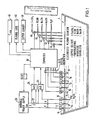
- Fig. 1 illustrates the invention used to control an electroless copper plating bath 4 where the principal constituents of the solution are copper sulfate (CuSo4), complexing agent, formaldehyde (HCOH, a hydroxide such as sodium or potassium hydroxide (NaOH) and a stabilizer such as a sodium cyanide (NaCN).
- CuSo4 copper sulfate
- complexing agent formaldehyde
- HCOH formaldehyde
- NaOH sodium or potassium hydroxide
- NaCN sodium cyanide
- a suitable electroless copper plating bath for the present invention includes one with a stabilizer system using both vanadium abd cyanide addition agents.
- the formulation is as follows: Copper Sulfate 0.028 moles/1 EDTA 0.075 moles/1 Formaldehyde 0.050 moles/1 pH (at 25°C) 11.55 (HCHO) (OH-) 0.5 0.0030
- Surfactant nonlphenylpolyethoxyphosphate
- SCE Specific gravity at 25°C
- An electroless metal plating bath solution includes a source of metal ions and a reducing agent for the metal ions.
- the reducing agent oxidizes on a catalytic surface and provides electrons on the surface. These electrons, in turn, reduce the metal ions to form a metal plating on the surface.
- electroless plating there are two half reactions, one in which the reducing agent is oxidized to produce the electrons and the other in which the electrons reduce the metal ions to plate out the metal.
- one of the half reactions is the reaction of a formaldehyde reducing agent (HCOH) in an alkaline solution (NaOH) to produce electrons on sites catalytic to the oxidation reaction.
- HCOH formaldehyde reducing agent
- NaOH alkaline solution
- This reaction is referred to as the 'anodic reaction' and takes place on catalytic conductive surfaces such as copper and certain other metals.
- the other half reaction, reducing the copper ions to plate out copper metal, is referred to as the 'cathodic reaction'.
- the anodic reaction rate is equal to and opposite to the cathodic reaction rate.
- the potential at which both, the anodic and the cathodic half reactions proceed without any external potential being applied is the 'mixed potential' of the plating solution, referred to herein as E mix .
- E mix the 'mixed potential' of the plating solution
- an external potential is supplied, e.g., from a power supply to the surface of an electrode
- the steady state is disturbed. If the electrode surface potential is positive relative to E mix , then the anodic reaction rate increases whereas, if the electrode surface potential is negative, the cathodic reaction rate increases.
- the intrinsic anodic reaction rate, R a is measured on the surface of an electrode where the potential is slightly more positive than the mixed potential of the solution.
- the intrinsic cathodic reaction rate, R c is measured on an electrode surface slightly more negative than the mixed potential.
- a sensor is placed in the bath.
- a counter electrode 10, a test electrode 11 and a reference electrode 8 are utilized to measure the formaldehyde, copper, stabilizer concentration, plating rate and quality of the plated copper.
- a pH sensing electrode 14 is used to measure the pH
- a cyanide sensing electrode 15 is used to measure the cyanide concentration
- ad the temperature of the bath is measured using a temperature sensing probe 16.
- the copper concentration also can be measured in situ utilizing a fiber optic spectrophotometric sensor 17. Specific gravity of the bath solution is measured by a probe 18.
- these sensors are configured within a common bracket which is placed in the bath.
- the bracket allows for easy insertion and removal of the sensors and probes.
- the potential E mix is measured using a calomel or a silver/silver chloride electrode as reference electrode 8 in combination with a platinum test electrode 11 with an electroless copper coating developed in the bath.
- the electrodes develop the mixed potential of the solution in about 5 seconds.
- An analog to digital (A/D) converter 26 is connected to electrodes 8 and 11 to sense the potential E mix and to provide a corresponding digital indication thereof.
- Electrodes 10 and 11 are platinum and, as previously mentioned, electrode 8 is a reference electrode such as a silver/silver chloride electrode (SCE).
- a variable power supply 20 is connected to apply a potential difference E between electrodes 10 and 11.
- a resistor 22 is connected in series with electrode 11 and is used to measure current I through the circuit. When the electrodes are placed in the bath, the plating bath solution completes the electrical circuit and the current flow I for the circuit passes through resistor 22.
- Power supply 20 is controlled to apply a potential sweep to the electrodes which drives the reaction on the surface of test electrode 11 anodic so as to measure the reducing agent concentration by driving the potential through the region of oxidation for that reducing agent. For accuracy, the potential sweep should begin at the mixed potential.
- the test electrode 11 is driven anodic by the power supply, i.e., the applied potential difference is positive at test electrode 11 and negative at counter electrode 10.
- the current I passing through resistor 22 is measured by measuring the potential drop across the resistor and convering to a digital value by means of an analog to digital (A/D) converter 24.
- the test electrode 11 is driven increasingly more anodic until a peak in the current response is reached.
- the sweep potential as measured by A/D converter 26 is increased at a 100 mV/sec. rate for about two seconds, as shown in Fig. 2A.
- the current and potential data from converters 24 and 26 are recorded during application of the sweep potential.
- the current reaches a peak value, I peak , which is a function of formaldehyde concentration.
- T k is provided by sensor 16 and the hydroxide concentration is derived from the measurement provided by pH sensor 14.
- the calibration constant is empirically determined based on comparison with known values of formaldehyde concentration.
- test electrode 11 and counter electrode 10, resistor 22 and power supply 20 is used to measure the plating rate of the bath as well as the intrinsic reation rates.
- a potential is applied to electrodes 11 and 10 to initially lower the potential of test electrode 11 (relative to reference electrode 8) so that the potential V is negative 40 mV as measured by converter 26.
- the potential is then changed in the positive direction to provide a potential sweep at the rate of 10 mV/sec. for 8 seconds.
- the potential sweeps from -40mV to +40mV.
- the potential drop across the resistor is measured representing the current I.
- the values of V and I are recorded during the sweep.
- the copper plating rate can be calculated from this data using the equations explained by Paunovic and Vitkavage in their article mentioned on page 4, lines 25-29, hereinbefore.
- the range of -40 mV to +40 mV is preferred, buth other ranges can be used. Generally, larger ranges provide a larger error indication caused by deviations from linearity whereas smaller ranges permit more accurate determination of the zero cross over point at E mix .
- the incremental values for E m are first converted to E j values according to the euqation: wherein V j is the absolute value of the incremental voltage relative to E mix , where b a is the Tafel slope of the anodic reaction and b c is the Tafel slope of the cathodic reaction.
- V j is the absolute value of the incremental voltage relative to E mix
- b a is the Tafel slope of the anodic reaction
- b c the Tafel slope of the cathodic reaction.
- the deposition rate can then be calculated using the equation:
- the copper plating quality index 'Q' is determined by comparing the intrinsic reactions for the anodic potential values (positive potential region in Fig. 2B) and the cathodic potential values (negative potential region in Fig. 2B) and, thus, for the anodic and cathodic reactions. If the ratio 'Q' of the intrinsic anodic reaction rate to the intrinsic cathodic reaction rate is about 1.0, the quality of the deposited copper will be adequate to pass the thermal shock test of exposure to molten solder at 288°C for 10 seconds. The ratio can be as high as 1.1 and still satisfactory quality electroless copper plating is produced.
- Fig. 2B are illustrated the current responses from the input of the -40 mV to +40mV potential sweep. For purposes of illustration, responses from three different solutions are shown. All three solutions are depicted with the same anodic response, but three different cathodic responses. The quality ratiosof the three different cathodic responses to the anodic responses in Fig. 2B are 1.23, 1.02 and 0.85.
- the cathodic and anodic reaction rates may vary and result in poor copper quality. If the anodic reaction produces too many electrons, copper deposits too rapidly and the copper atoms have insufficient time to find their correct location in the crystal lattice. If the copper quality index Q is below 1.0, high quality copper crystals are formed. If Q is in the range of 1.0 to 1.05, good crystals are formed but moderate corrective action should be taken to reduce Q; if Q is in the range of 1.05 to 1.1, stronger corrective action should be taken; and if Q exceeds 1.1, the work in process should be removed and the plating process should be shut down. Thus, for adequate copper quality, Q must be below 1.1, preferably below 1.05, and most preferably below 1.0. For illustrative purposes, Q for the electrodes copper plating bath formulation described above has been measured as 0.89.
- the copper concentration can conveniently de determined by measuring optical absorption by copper in the solution. This may be accomplished using a pair of fiber optic light conductors 17 placed in the bath to measure copper concentration. The ends of the conductors are placed facing each other with a premeasured space between the ends. A light beam is transmitted through one of the fiber optic conductors, through the plating solution and then through the other fiber conductor. A spectrophotometer is used to measure the intensity of the beam emerging from the conductors at the copper absorbing wavelength. As the copper ion concentration in the solution increases, more light is absorbed. The copper concentration of the bath can therefore be established as a function of measured light absorption.
- copper is analyzed by a cyclic voltammetric method similar to that used to analyze the formaldehyde.
- a potwential sweep moving in the negative direction from E mix is applied to the measuring electrode.
- the negative peak obtained is proportional to the copper concentration.
- the negative moving potential sweep for copper analysis takes place after measuring the plating ratio and before regenerating the electrode surface.
- the electrode surface is regenerated before measuring the formaldehyde current and also is regenerated before measuring the copper peak current.
- a measure for the specific gravity of the bath also is desirable since an excessively high specific gravity is an indication that the bath is plating improperly. If the specific gravity is in excess of a desired set point, water is added to the plating bath soution to bring the specific gravity back to allowable limits.
- the specific gravity may be measured by various known techniques, for example, as a function of the light index of refraction.
- a probe 18 in the form of a triangular compartment with transparent sides may be placed in the bath such that the plating bath solution flows through the center of the compartment.
- a beam of light, other than red, is refracted by the bath solution.
- the specific gravity of the bath is proportional to the degree of refraction which can be measured by a series of detectors in a linear array located outside the transparent triangular compartment.
- a probe 15 for measuring cyanide concentration in the plating bath can usefully be included. This probe involves reading the potential difference between a selective ion electrode and a reference electrode (Ag/AgCl). This potential increases with temperature so that a correction is needed to compensate for temperature.
- the test electrode 11 is periodically regenerated in order to achieve a reproducible reference surface for continuous in situ measurements. After completion of each measurement cycle, the test electrode is preferably regenerated to prepare for the next cycle of measurements.
- a substantial potential, e.g., +500 mV above the mixed potential is supplied by power supply 20 for at least about 45 seconds, and preferably longer, to strip the electrode of copper and oxidation by-products generated by the previous measurements. In the stripped condition, electrode 11 is restored to a clean platinum surface. Since the electrode is in an electroless plating bath, copper plates onto the electrode surface after the stripping pulse ceases. About 5 seconds are adequate to resurface the electrode with copper in preparation for a new measurement cycle. This capability to regenerate the electrode insitu is important becasue it eliminates the need for time consuming removal of the electrodes from the bath in order to clean or regenerate their surfaces and is thus a prerequisite to real time control of the bath.
- Fig. 4 shows a voltage profile for a repetitive measurement cycle.
- no potential is applied to the electrodes.
- the electrodes are permitted to electrically float and equilibrate in the bath solution to assume the mixed potential E mix which is measured and recorded.
- This sweep provides data for determining the formaldehyde and stabilizer concentrations.
- a large positive stripping pulse 124 (500 mV above E mix for about 40 seconds) is applied to strip the platinum electrode of copper and other reaction by-products.
- the electroless plating solution resurfaces the test electrode with a clean copper coating.
- the overall cycle is about 1 minute, but could be shorter is desired.
- the voltage profile can be tried.
- the first and second velotage sweeps can be interchanged in time.
- the potential sweeps may be combined into a single sweep going, for example, from -40 mV to +200mV.
- Each cycle should include a large stripping pulse followed by a period which permits resurfacing of the test electrode.
- the intrinsic anodic and cathodic reaction rates are calculated.
- the second voltage sweep is omitted.
- replenishments of the reducing agent, formaldehyde and/or the metal ion, copper are made automatically, in order to maintain constant intrinsic reaction rates.
- the second voltage cycle is omitted, the regenerated electrode surface can be reused for 10 to 15 sweep cycles before regenerating the electrode again.
- Another test voltage profile which can be used in analyzing an electroless copper test solution is a truncated triangular wave which starts at a cathodic voltage of approximately -735 mV vs. the saturated calomel electrode.
- the voltage is increased at a rate of 25 mV/sec. for 2.3 seconds until it reaches -160 mV vs. saturated calomel electrode.
- the current recorded during this portion of the test voltage profile is used to calculate both the quality index and the formaldehyde concentration.
- the currents between -30 mV vs. E mix and E mix are used to calculate the intrinsic cathodic reaction rate.
- the currents from E mix to +30 mV vs. E mix are used to calculate the intrinsic anodic reaction rate.
- Formaldehyde concentration is determined from the peak current during the sweep. At -160 mV, copper is dissolved from the electrode. The voltage is held at -160 mV until the copper stripping current drops indicating that all the copper has been stripped from the electrode. The voltage is then swept in a negative direction at optionally -25 mV/sec. until it reaches -735 mV vs. the saturated calomel electrode. The voltage is held at -735 mV until the current rises indicating the electrode has been resurfaces with a fresh copper layer and is ready for a new cycle.
- the potential profile and the magnitudes of the applied potential depend on the type of plating solution.
- an electroless nickel plating solution comprising nickel ions and sodium hypophosphite (NaH2PO2) would use a similar voltage profile but corresponding to the reaction rates of the hypophosphite.
- Different constituents, particularly different reducing agents, in the bath require adjustments in the magnitudes of the applied potentials.
- the reducing agents that are suitable for the reduction of copper ions are formaldehyde and formaldehyde compounds such as formaldehyde bisulfite, paraformalde hyde, and trioxane, and boron hydrides such as boranes and borohydrides such as alkali metal borohydrides.
- a three electrode system including electrodes 8, 10 and 11 is shown in Fig. 1 and described hereinbefore, similar results can be achieved using two electrodes.
- the reference electrode 8 can be omitted if the remaining electrode 10 is made sufficiently large that current flow through the electrode does not significantly change the surface potential.
- the composition and operation of the plating solution is controlled by digital computer 30.
- the computer 30 receives information from sensors 8-18.
- the computer also controls power supply 20 in turn to control the potential supply to electrodes 10 and 11 so as to provide the required sweep potentials, stripping pulses and equilibration intervals.
- the values of I and V are measured via converters 24 and 26, and the incremental measured values are stored for later analysis.
- Computer 30 also controls valves 40 to 44 which control additions to the bath. In the example shown in Fig. 1, the valves respectively control the addition of copper sulfate, formaldehyde, sodium cyanide, sodium hydroxide, and water to the plating bath.
- Valves 40-44 are preferably of the open/shut type where the volume of chemical addition is controlled by controlling the duration of the interval during which the valve is open.
- the computer obtains information from the various sensors, analyzes the data and then opens the respective valves for predetermined time intervals to thereby provide correct quantity of chemical addition required in the bath.
- the computer can also provide various output indications such as a display 46 of the E mix value, a display 48 indicating the plating rate, and a display 49 indicating the copper quality.
- a display 46 of the E mix value is desirable since departure from the normal range indicates improper operation of the plating bath.
- An indication of the plating rate is desirable so the operator can determine the proper length of time required to achieve desired plating thickness.
- the copper quality indication is, of course, important to assure proper operation free from crack or other defects.
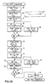
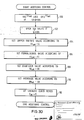
- the program for computer 30 is illustrated in flow diagram from in Figs. 3A-3D.
- Fig. 3A illustrates the overall computer program including a data aquisition sub-routine 50 followed by data analysis sub-routine 52 which, in turn, is followed by an addition control sub-routine 54.
- the control system operates in regular cycles of approximately 1 min. as indicated in Fig. 4.
- data is acquired an analyzed and the results used to control additions to the bath.
- a clock is used to time the cycle, and a clock reset 56 is used to initiate a new cycle after completion of the 1 min. cycle interval.
- a time delay 60 is provided for approximately 5 seconds so that 10 and 11 can equilibrate to the plating solution potential.
- the computer reads the potential E mix obtained via A/D converter 26 (Fig. 1) and stores this value in step 62.
- the time delay in step 68 is adjusted so that the voltage sweep from zero to 200 mV takes approximately 2 seconds.
- decision 67 has determined that the first sweep potential has reached its maximum value
- the program progresses to step 70 during which the computer reads and stores values from pH probe 14, temperature T k probe 16, copper concentration probe 17, cyanide concentration probe 15 and specific gravity probe 18.
- the measured values all are stored at appropriate locations in the computer memory.
- step 71 the program provides for a 5 seconds delay for the electrodes to equilibrate prior to the second voltage sweep.
- the program next progresses through another loop which provides the second potential sweep (sweep 122, Fig. 4) to electrodes 10 and 11 through suitable control of power supply 20.
- the first step in the loop is to increment the value of E ps and then to read and store the values of potential V and current I in steps 74 and 76.
- the time delay in step 78 is adjusted so that the voltage sweep from -40 mV to +40 mV takes approximately 8 seconds.
- a determination that V is equal to +40 mV in decision 77 indicates completion of the data acquisition procedure.
- the program sets the power supply to 500 mV to start the stripping pulse (pulse 124, Fig. 4) which continues during the data analysis and addition control sub-routines.
- step 80 the computer first analyzes the data in a first data array which is the data acquired during the first potential sweep applied to electrodes 10 and 11 (i.e., steps 65-68). The data is analyzed to determine the highest current value I peak and the corresponding voltage E m .
- the peak current value can be determined using a simple program whereby the initial value of current is placed in the accumulator and compared with each of the subsequent values. If the subsequent value is greater than the value in the accumulator, then the subsequent value is substituted for the accumulator value.
- the value in the accumulator will be the largest value I peak of current in the data array.
- the corresponding voltage is E peak .
- the constant K is determined empirically from laboratory bench work.
- the data is analyzed from the second data array which was acquired during the second voltage sweep from -40 mV to +40 mV (i.e., steps 74-78).
- the first step is to determine the E j values according to the equation: wherein V j is the absolute value of the incremental voltage relative to E mix , b a is the anodic reaction rate and b c is the cathodic reaction rate.
- the plating rate P can be determined in step 86 using the equation: For the overall plating rate for the process, the summations cover the entire range from -40 mV to +40 mV. For determining the copper quality index, Q, the intrinsic anodic reaction rate R a is determined over the range from zero to +40 mV in step 88 whereas the intrinsic cathodic reaction rate R c is determined over the range from -40 mV to zero in step 90.
- the equations for R a and R c are as follows:
- the copper quality index Q is calculated in step 92 and is the ratio of R a to R c .
- a copper quality index Q greater than 1.0 is undesirable and requires correction.
- a quality index Q greater than 1.1 normally requires shut down of the bath.
- the computer can also determine the stabilizer concentration which is a function of the voltage E peak .
- steps 80-94 provide the analysis found most useful in controlling the plating process and in displaying status indicators.
- the flow diagram for the additions control sub-routine 54 is shown in Fig. 3D.
- the additions control is achieved by comparing the various measured concentrations and quality indexes with corresponding set points.
- the valves 40-44 then are controlled to add chemicals to the bath in accordance with the departures from the set points.
- the program first analyzes the copper quality index Q to determine if Q is in the range from 1.0 and 1.05. This is the range where mild bath adjustment is indicated which can normally be achieved by adjusting the set points for copper and formaldehyde.
- step 100 if Q is in the range of 1.0 amd 1.05, the copper concentration set point CC set is incremented or increased and the formaldehyde concentration set point FC set is decremented or decreased. It also may be desirable to keep track of the number of such adjustments since,if the quality index Q does not drop below 1.0 after three iterations, more drastic corrective action may be required.
- step 102 the program determines if the copper quality index Q exceeds 1.05. If so, the system opensvalve 44 to add waer to the bath. The water addition dilutes the bath which then is replenished by the addition of new chemicals as the system re-establishes the concentration set point values.
- step 104 the copper concentration CC is compared to to copper concentration set point CC set , and valve 40 is opened for a time period corresponding to the degree of departure from the set point.
- step 106 the formaldehyde concentration FC is compared with the formaldehyde concentration set point FC set and valve 41 is opened for a time period corresponding to the degree of departure from the set point value.
- step 108 the stabilizer concentration SC is compared with the stabilizer concentration set point SC set and valve 42 is opened for a period of time corresponding to the degree of departure from the set point value.
- step 110 the hydroxyl concentration OH is compared with the hydroxyl set point OH set to control the opened interval for valve 43.
- the computer in step 112, awaits the clock reset in step 56 to set the power supply voltage to zero to thereby terminate the stripping pulse.
- the test electrode 11 is thereafter resurfaced during the five seconds interval provided by time delay 60.
Landscapes
- Chemical & Material Sciences (AREA)
- General Chemical & Material Sciences (AREA)
- Chemical Kinetics & Catalysis (AREA)
- Engineering & Computer Science (AREA)
- Materials Engineering (AREA)
- Mechanical Engineering (AREA)
- Metallurgy (AREA)
- Organic Chemistry (AREA)
- Electrochemistry (AREA)
- Chemically Coating (AREA)
- Electroplating And Plating Baths Therefor (AREA)
Applications Claiming Priority (2)
| Application Number | Priority Date | Filing Date | Title |
|---|---|---|---|
| US926362 | 1986-10-31 | ||
| US06/926,362 US4814197A (en) | 1986-10-31 | 1986-10-31 | Control of electroless plating baths |
Publications (3)
| Publication Number | Publication Date |
|---|---|
| EP0265901A2 true EP0265901A2 (fr) | 1988-05-04 |
| EP0265901A3 EP0265901A3 (en) | 1989-05-10 |
| EP0265901B1 EP0265901B1 (fr) | 1993-01-27 |
Family
ID=25453110
Family Applications (1)
| Application Number | Title | Priority Date | Filing Date |
|---|---|---|---|
| EP87115717A Expired - Lifetime EP0265901B1 (fr) | 1986-10-31 | 1987-10-27 | Contrôle des bains de dépôt chimique |
Country Status (14)
| Country | Link |
|---|---|
| US (1) | US4814197A (fr) |
| EP (1) | EP0265901B1 (fr) |
| JP (1) | JP2759322B2 (fr) |
| KR (1) | KR880701790A (fr) |
| AU (1) | AU602041B2 (fr) |
| BR (1) | BR8707517A (fr) |
| CA (1) | CA1265710A (fr) |
| CH (1) | CH674582A5 (fr) |
| DE (1) | DE3736429C2 (fr) |
| ES (1) | ES2038151T3 (fr) |
| FR (1) | FR2609806B1 (fr) |
| GB (1) | GB2207249B (fr) |
| NL (1) | NL8702592A (fr) |
| WO (1) | WO1988003180A1 (fr) |
Cited By (5)
| Publication number | Priority date | Publication date | Assignee | Title |
|---|---|---|---|---|
| EP0340649A1 (fr) * | 1988-04-29 | 1989-11-08 | AMP-AKZO CORPORATION (a Delaware corp.) | Procédé et bain pour effectuer un dépôt chimique de cuivre exempt de fissures |
| EP0564780A1 (fr) * | 1992-04-06 | 1993-10-13 | Shipley Company Inc. | Méthode et dispositif pour maintenir stable une solution de placage sans courant |
| WO2008058250A1 (fr) * | 2006-11-08 | 2008-05-15 | Surfect Technologies, Inc. | Système et procédé de régulation d'un procédé de placage anélectrolytique |
| EP2192405A1 (fr) * | 2008-11-26 | 2010-06-02 | Atotech Deutschland Gmbh | Procédé de contrôle d'additifs de stabilisateur dans un métal autocatalytique et électrolytes à placage d'alliage métallique |
| US11761090B2 (en) | 2015-12-03 | 2023-09-19 | Atotech Deutschland GmbH & Co. KG | Method for monitoring the total amount of sulphur containing compounds in a metal plating bath |
Families Citing this family (19)
| Publication number | Priority date | Publication date | Assignee | Title |
|---|---|---|---|---|
| ES2039403T3 (es) * | 1986-10-31 | 1993-10-01 | Amp-Akzo Corporation (A Delaware Corp.) | Metodo para depositar sin electricidad cobre de alta calidad. |
| JP2888001B2 (ja) * | 1992-01-09 | 1999-05-10 | 日本電気株式会社 | 金属メッキ装置 |
| US5352350A (en) * | 1992-02-14 | 1994-10-04 | International Business Machines Corporation | Method for controlling chemical species concentration |
| CA2154173C (fr) * | 1993-01-19 | 2002-03-12 | William E. Ardrey, Jr. | Capteur modulaire des caracteristiques d'un fluide et regulateur de distribution d'adjuvants |
| US5368715A (en) * | 1993-02-23 | 1994-11-29 | Enthone-Omi, Inc. | Method and system for controlling plating bath parameters |
| DE19546206A1 (de) * | 1994-12-19 | 1996-06-20 | At & T Corp | Verfahren zum Prüfen von Materialien zur Verwendung bei der chemischen oder außenstromlosen Beschichtung |
| US5631845A (en) * | 1995-10-10 | 1997-05-20 | Ford Motor Company | Method and system for controlling phosphate bath constituents |
| KR100201377B1 (ko) * | 1995-10-27 | 1999-06-15 | 김무 | 다성분 도금용액의 농도조절장치 |
| US5993892A (en) * | 1996-09-12 | 1999-11-30 | Wasserman; Arthur | Method of monitoring and controlling electroless plating in real time |
| US6565729B2 (en) * | 1998-03-20 | 2003-05-20 | Semitool, Inc. | Method for electrochemically depositing metal on a semiconductor workpiece |
| US7189318B2 (en) * | 1999-04-13 | 2007-03-13 | Semitool, Inc. | Tuning electrodes used in a reactor for electrochemically processing a microelectronic workpiece |
| US7020537B2 (en) * | 1999-04-13 | 2006-03-28 | Semitool, Inc. | Tuning electrodes used in a reactor for electrochemically processing a microelectronic workpiece |
| AU2001259504A1 (en) * | 2000-05-24 | 2001-12-03 | Semitool, Inc. | Tuning electrodes used in a reactor for electrochemically processing a microelectronic workpiece |
| PL342328A1 (en) * | 2000-09-01 | 2002-03-11 | Kghm Polska Miedz Sa | Method fo measuring concentration of copper ions in industrial electrolytes |
| WO2006007533A1 (fr) * | 2004-07-01 | 2006-01-19 | Tracedetect, Inc. | Procédé de nettoyage par les ultrasons d'une électrode de travail dans un élément électrochimique, utile pour la mesure automatique de métaux en traces |
| JP2007051362A (ja) * | 2005-07-19 | 2007-03-01 | Ebara Corp | めっき装置及びめっき液の管理方法 |
| US8172627B2 (en) | 2008-12-03 | 2012-05-08 | Tyco Electronics Corporation | Electrical connector with plated plug and receptacle |
| EP2821780B1 (fr) | 2013-07-02 | 2018-05-23 | Ancosys GmbH | Prise d'empreintes in-situ pour dépôt électrochimique et/ou gravure électrochimique |
| CN116219413B (zh) * | 2023-02-23 | 2024-10-22 | 江西景旺精密电路有限公司 | 一种金缸mto防呆的方法 |
Family Cites Families (27)
| Publication number | Priority date | Publication date | Assignee | Title |
|---|---|---|---|---|
| US2851655A (en) * | 1956-09-25 | 1958-09-09 | Foxboro Co | Amperometric continuous measurement system |
| US3401065A (en) * | 1964-08-18 | 1968-09-10 | Amchem Prod | Automatic control of nitrite addition in acid phosphate coating solutions |
| US3532519A (en) * | 1967-11-28 | 1970-10-06 | Matsushita Electric Industrial Co Ltd | Electroless copper plating process |
| JPS5036197B1 (fr) * | 1968-12-24 | 1975-11-21 | ||
| US3959108A (en) * | 1971-12-27 | 1976-05-25 | Plumpe Jr William H | System for automatically measuring and controlling the sulfate content of a chromium plating solution |
| US4096301A (en) * | 1976-02-19 | 1978-06-20 | Macdermid Incorporated | Apparatus and method for automatically maintaining an electroless copper plating bath |
| GB1585057A (en) * | 1976-06-28 | 1981-02-25 | Ici Ltd | Sensing concentration of coating solution |
| JPS539234A (en) * | 1976-07-14 | 1978-01-27 | Tokyo Shibaura Electric Co | Method of adjusting concentration of reducing agent for nonnelectrolytic plating solution |
| JPS539235A (en) * | 1976-07-14 | 1978-01-27 | Tokyo Shibaura Electric Co | Method of adjusting concentration of nonnelectrolytic plating solution |
| JPS539233A (en) * | 1976-07-14 | 1978-01-27 | Tokyo Shibaura Electric Co | Method of adjusting concentration of nonnelectrolytic copper plating solution |
| US4132605A (en) * | 1976-12-27 | 1979-01-02 | Rockwell International Corporation | Method for evaluating the quality of electroplating baths |
| DE2711989C2 (de) * | 1977-03-18 | 1980-04-30 | Siemens Ag, 1000 Berlin Und 8000 Muenchen | Elektrochemische Bestimmung von SchwermetaUen in Wasser |
| US4209331A (en) * | 1978-05-25 | 1980-06-24 | Macdermid Incorporated | Electroless copper composition solution using a hypophosphite reducing agent |
| IT1112649B (it) * | 1978-07-28 | 1986-01-20 | Oxon Italia Spa | Composto chimico eterociclio 6-fenil-(1,2,3)-oxadiazolo-(4,5 d)-piridazin-7(6h)-one e procedimento per la sua produzione |
| US4336111A (en) * | 1978-11-02 | 1982-06-22 | The Boeing Company | Method for determining the strength of a metal processing solution |
| JPS5926660B2 (ja) * | 1979-03-07 | 1984-06-29 | 株式会社東芝 | 無電解メツキ反応の測定方法 |
| JPS55158554A (en) * | 1979-05-28 | 1980-12-10 | Nissan Eng Kk | Apparatus for measuring concentration of oxidating and reducing substance |
| US4353933A (en) * | 1979-11-14 | 1982-10-12 | C. Uyemura & Co., Ltd. | Method for controlling electroless plating bath |
| JPS6016517B2 (ja) * | 1979-12-29 | 1985-04-25 | 上村工業株式会社 | 無電解めつき制御方法 |
| JPS56120943A (en) * | 1980-02-29 | 1981-09-22 | Hitachi Ltd | Manufacture of ph-detecting electrode |
| JPS5841344A (ja) * | 1981-09-07 | 1983-03-10 | Baionikusu Kiki Kk | ボルタンメトリ−分析法 |
| DE3473890D1 (en) * | 1983-07-25 | 1988-10-13 | Hitachi Ltd | Electroless copper plating solution |
| JPS60104246A (ja) * | 1983-11-11 | 1985-06-08 | C Uyemura & Co Ltd | 化学銅めつき浴中のホルムアルデヒドの分析方法 |
| US4565575A (en) * | 1984-11-02 | 1986-01-21 | Shiplay Company Inc. | Apparatus and method for automatically maintaining an electroless plating bath |
| US4623554A (en) * | 1985-03-08 | 1986-11-18 | International Business Machines Corp. | Method for controlling plating rate in an electroless plating system |
| US4631116A (en) * | 1985-06-05 | 1986-12-23 | Hughes Aircraft Company | Method of monitoring trace constituents in plating baths |
| US4654126A (en) * | 1985-10-07 | 1987-03-31 | International Business Machines Corporation | Process for determining the plating activity of an electroless plating bath |
-
1986
- 1986-10-31 US US06/926,362 patent/US4814197A/en not_active Expired - Lifetime
-
1987
- 1987-10-27 EP EP87115717A patent/EP0265901B1/fr not_active Expired - Lifetime
- 1987-10-27 ES ES198787115717T patent/ES2038151T3/es not_active Expired - Lifetime
- 1987-10-28 DE DE3736429A patent/DE3736429C2/de not_active Expired
- 1987-10-29 CH CH4251/87A patent/CH674582A5/de not_active IP Right Cessation
- 1987-10-29 GB GB8725399A patent/GB2207249B/en not_active Expired - Lifetime
- 1987-10-30 FR FR8715091A patent/FR2609806B1/fr not_active Expired - Fee Related
- 1987-10-30 AU AU83269/87A patent/AU602041B2/en not_active Ceased
- 1987-10-30 JP JP62507140A patent/JP2759322B2/ja not_active Expired - Lifetime
- 1987-10-30 WO PCT/US1987/002854 patent/WO1988003180A1/fr not_active Ceased
- 1987-10-30 NL NL8702592A patent/NL8702592A/nl not_active Application Discontinuation
- 1987-10-30 BR BR8707517A patent/BR8707517A/pt not_active IP Right Cessation
- 1987-11-02 CA CA000550806A patent/CA1265710A/fr not_active Expired - Lifetime
-
1988
- 1988-06-30 KR KR1019880700759A patent/KR880701790A/ko not_active Ceased
Cited By (8)
| Publication number | Priority date | Publication date | Assignee | Title |
|---|---|---|---|---|
| EP0340649A1 (fr) * | 1988-04-29 | 1989-11-08 | AMP-AKZO CORPORATION (a Delaware corp.) | Procédé et bain pour effectuer un dépôt chimique de cuivre exempt de fissures |
| EP0564780A1 (fr) * | 1992-04-06 | 1993-10-13 | Shipley Company Inc. | Méthode et dispositif pour maintenir stable une solution de placage sans courant |
| US5484626A (en) * | 1992-04-06 | 1996-01-16 | Shipley Company L.L.C. | Methods and apparatus for maintaining electroless plating solutions |
| WO2008058250A1 (fr) * | 2006-11-08 | 2008-05-15 | Surfect Technologies, Inc. | Système et procédé de régulation d'un procédé de placage anélectrolytique |
| EP2192405A1 (fr) * | 2008-11-26 | 2010-06-02 | Atotech Deutschland Gmbh | Procédé de contrôle d'additifs de stabilisateur dans un métal autocatalytique et électrolytes à placage d'alliage métallique |
| WO2010060906A1 (fr) * | 2008-11-26 | 2010-06-03 | Atotech Deutschland Gmbh | Procédé de régulation d'additifs de stabilisation dans des électrolytes de dépôt auto-catalytique de métal et d’alliage métallique |
| CN102227628A (zh) * | 2008-11-26 | 2011-10-26 | 安美特德国有限公司 | 用于控制无电镀金属和金属合金镀用电解液中稳定添加剂的方法 |
| US11761090B2 (en) | 2015-12-03 | 2023-09-19 | Atotech Deutschland GmbH & Co. KG | Method for monitoring the total amount of sulphur containing compounds in a metal plating bath |
Also Published As
| Publication number | Publication date |
|---|---|
| EP0265901B1 (fr) | 1993-01-27 |
| DE3736429A1 (de) | 1988-05-19 |
| KR880701790A (ko) | 1988-11-05 |
| GB8725399D0 (en) | 1987-12-02 |
| CA1265710A (fr) | 1990-02-13 |
| GB2207249A (en) | 1989-01-25 |
| ES2038151T3 (es) | 1993-07-16 |
| BR8707517A (pt) | 1989-02-21 |
| AU8326987A (en) | 1988-05-25 |
| CH674582A5 (fr) | 1990-06-15 |
| JP2759322B2 (ja) | 1998-05-28 |
| AU602041B2 (en) | 1990-09-27 |
| WO1988003180A1 (fr) | 1988-05-05 |
| GB2207249B (en) | 1991-03-27 |
| FR2609806B1 (fr) | 1993-09-10 |
| JPH01501324A (ja) | 1989-05-11 |
| US4814197A (en) | 1989-03-21 |
| EP0265901A3 (en) | 1989-05-10 |
| FR2609806A1 (fr) | 1988-07-22 |
| NL8702592A (nl) | 1988-05-16 |
| DE3736429C2 (de) | 1988-12-01 |
Similar Documents
| Publication | Publication Date | Title |
|---|---|---|
| EP0265901B1 (fr) | Contrôle des bains de dépôt chimique | |
| EP0242530B1 (fr) | Procédé d'analyse de la concentration d'un additif | |
| US5223118A (en) | Method for analyzing organic additives in an electroplating bath | |
| EP1203950B1 (fr) | Analyse de bains de placage | |
| US4917777A (en) | Method for analyzing additive concentration | |
| CA1072632A (fr) | Dispositif et methode pour evaluer la qualite des bains de galvanoplastie | |
| EP0564780B1 (fr) | Méthode et dispositif pour maintenir stable une solution de placage sans courant | |
| US4707378A (en) | Method and apparatus for controlling the organic contamination level in an electroless plating bath | |
| EP0180090A2 (fr) | Système et procédé pour la surveillance et la maintenance automatique des concentrations désirées dans les bains métalliques de plaquage | |
| JP5335096B2 (ja) | 無電解金属または金属合金めっき電解質中の安定化添加剤の濃度測定方法およびその制御方法 | |
| US20060151327A1 (en) | Analysis method | |
| US7384535B2 (en) | Bath analysis | |
| CA1225549A (fr) | Moniteur pour bain de placage sans electrolyse | |
| WO1991016472A1 (fr) | Procede pour la regulation de bains de metallisation | |
| DE19957067B4 (de) | Verfahren und Anordnung zur Überwachung der stromlosen Metallabscheidung | |
| US5955150A (en) | Method for testing materials for use in electroless plating | |
| Kim | An analysis of mixed-potential theory in electroless copper deposition | |
| JPH0211786A (ja) | 酸の銅浴からの直流的銅析出の監視、制御方法及び装置 |
Legal Events
| Date | Code | Title | Description |
|---|---|---|---|
| PUAI | Public reference made under article 153(3) epc to a published international application that has entered the european phase |
Free format text: ORIGINAL CODE: 0009012 |
|
| AK | Designated contracting states |
Kind code of ref document: A2 Designated state(s): AT DE ES FR IT SE |
|
| PUAL | Search report despatched |
Free format text: ORIGINAL CODE: 0009013 |
|
| AK | Designated contracting states |
Kind code of ref document: A3 Designated state(s): AT DE ES FR IT SE |
|
| 17P | Request for examination filed |
Effective date: 19890721 |
|
| 17Q | First examination report despatched |
Effective date: 19910403 |
|
| RAP1 | Party data changed (applicant data changed or rights of an application transferred) |
Owner name: AMP-AKZO CORPORATION (A DELAWARE CORP.) |
|
| RAP1 | Party data changed (applicant data changed or rights of an application transferred) |
Owner name: AMP-AKZO CORPORATION |
|
| GRAA | (expected) grant |
Free format text: ORIGINAL CODE: 0009210 |
|
| RBV | Designated contracting states (corrected) |
Designated state(s): ES IT SE |
|
| AK | Designated contracting states |
Kind code of ref document: B1 Designated state(s): ES IT SE |
|
| ITF | It: translation for a ep patent filed | ||
| REG | Reference to a national code |
Ref country code: DE Ref legal event code: 8566 |
|
| REG | Reference to a national code |
Ref country code: ES Ref legal event code: FG2A Ref document number: 2038151 Country of ref document: ES Kind code of ref document: T3 |
|
| PG25 | Lapsed in a contracting state [announced via postgrant information from national office to epo] |
Ref country code: SE Effective date: 19931028 Ref country code: ES Free format text: LAPSE BECAUSE OF THE APPLICANT RENOUNCES Effective date: 19931028 |
|
| PLBE | No opposition filed within time limit |
Free format text: ORIGINAL CODE: 0009261 |
|
| STAA | Information on the status of an ep patent application or granted ep patent |
Free format text: STATUS: NO OPPOSITION FILED WITHIN TIME LIMIT |
|
| 26N | No opposition filed | ||
| EUG | Se: european patent has lapsed |
Ref document number: 87115717.8 Effective date: 19940510 |
|
| REG | Reference to a national code |
Ref country code: ES Ref legal event code: FD2A Effective date: 19991007 |
|
| PG25 | Lapsed in a contracting state [announced via postgrant information from national office to epo] |
Ref country code: IT Free format text: LAPSE BECAUSE OF NON-PAYMENT OF DUE FEES;WARNING: LAPSES OF ITALIAN PATENTS WITH EFFECTIVE DATE BEFORE 2007 MAY HAVE OCCURRED AT ANY TIME BEFORE 2007. THE CORRECT EFFECTIVE DATE MAY BE DIFFERENT FROM THE ONE RECORDED. Effective date: 20051027 |