EP2192680B1 - Procédé de contrôle du démarrage d'un moteur asynchrone en utilisant un contrôle alpha à boucle fermée - Google Patents
Procédé de contrôle du démarrage d'un moteur asynchrone en utilisant un contrôle alpha à boucle fermée Download PDFInfo
- Publication number
- EP2192680B1 EP2192680B1 EP09015163.0A EP09015163A EP2192680B1 EP 2192680 B1 EP2192680 B1 EP 2192680B1 EP 09015163 A EP09015163 A EP 09015163A EP 2192680 B1 EP2192680 B1 EP 2192680B1
- Authority
- EP
- European Patent Office
- Prior art keywords
- motor
- firing angle
- alpha
- induction motor
- lim
- Prior art date
- Legal status (The legal status is an assumption and is not a legal conclusion. Google has not performed a legal analysis and makes no representation as to the accuracy of the status listed.)
- Expired - Lifetime
Links
- 238000000034 method Methods 0.000 title claims description 34
- 230000006698 induction Effects 0.000 title description 85
- 238000010304 firing Methods 0.000 claims description 82
- 238000012544 monitoring process Methods 0.000 claims 2
- 238000013459 approach Methods 0.000 description 15
- 239000007858 starting material Substances 0.000 description 13
- 238000004804 winding Methods 0.000 description 11
- 230000010355 oscillation Effects 0.000 description 6
- 239000007787 solid Substances 0.000 description 5
- 230000001133 acceleration Effects 0.000 description 3
- XUIMIQQOPSSXEZ-UHFFFAOYSA-N Silicon Chemical compound [Si] XUIMIQQOPSSXEZ-UHFFFAOYSA-N 0.000 description 2
- 230000000694 effects Effects 0.000 description 2
- 229910052710 silicon Inorganic materials 0.000 description 2
- 239000010703 silicon Substances 0.000 description 2
- 102100030796 E3 ubiquitin-protein ligase rififylin Human genes 0.000 description 1
- 101710128004 E3 ubiquitin-protein ligase rififylin Proteins 0.000 description 1
- 230000015556 catabolic process Effects 0.000 description 1
- 238000010276 construction Methods 0.000 description 1
- 238000001816 cooling Methods 0.000 description 1
- 238000013016 damping Methods 0.000 description 1
- 230000007423 decrease Effects 0.000 description 1
- 230000003111 delayed effect Effects 0.000 description 1
- 230000005611 electricity Effects 0.000 description 1
- 230000001939 inductive effect Effects 0.000 description 1
- 230000010354 integration Effects 0.000 description 1
- 238000004519 manufacturing process Methods 0.000 description 1
- 230000000135 prohibitive effect Effects 0.000 description 1
- 230000010349 pulsation Effects 0.000 description 1
- 230000001960 triggered effect Effects 0.000 description 1
- 238000011144 upstream manufacturing Methods 0.000 description 1
Images



Classifications
-
- H—ELECTRICITY
- H02—GENERATION; CONVERSION OR DISTRIBUTION OF ELECTRIC POWER
- H02P—CONTROL OR REGULATION OF ELECTRIC MOTORS, ELECTRIC GENERATORS OR DYNAMO-ELECTRIC CONVERTERS; CONTROLLING TRANSFORMERS, REACTORS OR CHOKE COILS
- H02P1/00—Arrangements for starting electric motors or dynamo-electric converters
- H02P1/16—Arrangements for starting electric motors or dynamo-electric converters for starting dynamo-electric motors or dynamo-electric converters
- H02P1/26—Arrangements for starting electric motors or dynamo-electric converters for starting dynamo-electric motors or dynamo-electric converters for starting an individual polyphase induction motor
Definitions
- This invention relates to motor controls, and in particular, to a method of controlling the starting of an AC induction motor with a soft starter.
- an adjustable frequency controller is interconnected to the AC induction motor.
- the adjustable frequency controller is comprised of an inverter which uses solid state switches to convert DC power to stepped waveform AC power.
- a waveform generator produces switching signals for the inverter under control of a microprocessor. While adjustable frequency controllers efficiently control the motor speed and the energy used by an AC induction motor, use of such types of controllers may be cost prohibitive. Further, since many applications of AC induction motors do not require sophisticated frequency and voltage control, an alternative to adjustable frequency controllers has been developed.
- Soft starters operate using the principal of phase control whereby the line currents supplied to the AC induction motor are controlled by means of anti-parallel thyristor switches. Soft starters offer two major benefits for a user. First, use of a soft starter reduces the motor torque pulsation at startup of the AC induction motor which, in turn, results in less mechanical strain on the load. Second, use of a soft starter reduces the motor inrush current at startup of the AC induction motor which, in turn, places less stress on upstream electrical systems.
- the anti-parallel thyristor switches are provided in each supply line. These thyristor switches in each supply line are fired to control the fraction of the half cycle over which current is conducted to the motor (known as the conduction period).
- the non-conducting period of each half cycle (known as the hold-off angle or the notch width) is visible as a notch in the voltage waveform at each motor terminal. During this period, no current flows to the motor terminals.
- the thyristor switches in the supply line to the motor terminals are fired to restart their conduction.
- the conduction through the thyristor switches continues until the current, once again, becomes zero at some point in the next half cycle and the thyristor switches reopen.
- phase control by varying the duration of the non-conducting period, the voltage and current supplied to the AC induction motor may be controlled.
- the anti-parallel thyristor switches may be provided inside the delta. Positioning the anti-parallel thyristor switches within the delta allows for use of smaller electrical components since the phase current magnitudes are less than the line current magnitudes.
- alpha control the thyristor switches are sequentially fired at a certain angle, alpha ( ⁇ ), after the zero crossing times of the corresponding phase voltages.
- gamma control the thyristor switches are sequentially fired at a certain angle, gamma ( ⁇ ), after the zero crossing times of the corresponding phase currents. It has been found that alpha control is more stable than gamma control in starting and bringing the AC induction motor to near operating speed because the zero crossings of the phase voltage are fixed while the zero crossings of the phase current move as the speed of the AC induction motor changes.
- gamma control is preferred once the motor has accelerated to the point where its speed is above the breakdown speed, in other words, the speed at which the slope of the speed/torque curve is zero. This is due to the fact that the motor's torque production is a delayed function of speed. Therefore, as the motor accelerates to full speed, it overshoots before the electrical torque balances the mechanical load. Once the motor overshoots, the electrical torque eventually becomes negative and the speed undershoots its steady state value causing torque to become positive again. It may take several cycles of this oscillation to reach steady state when the terminal voltage on the motor is fixed.
- a motor controller has: thyristors for connecting the motor to a source of AC electrical energy; motor voltage zero crossing circuitry and motor current zero crossing circuitry for measuring a LAG TIME indicative of the time interval between the event of voltage applied; to the motor crossing zero and current flow to the motor reaching zero; a microprocessor generating a desired OFF TIME indicative of a desired time interval between the event of current flow to the motor reaching zero and firing of the thyristors; phase angle controller circuitry for firing the thyristors at a firing time after the event that the voltage applied to the motor crosses zero, the firing time being computed by adding the LAG TIME and the OFF TIME.
- the desired OFF TIME may be computed from an energy saving apparatus for adjusting the voltage applied to the motor to provide efficient operation for a highly loaded motor.
- EP 0 446 936 A2 concerns a three-phase motor operated by a controller having sets of thyristors which when triggered switch electricity from each phase of a supply to the motor.
- the motor is started by triggering the thyristors to be conductive during successively greater portions of each cycle of the AC power.
- a contactor is connected in parallel with the thyristors to provide apply power to the motor once it reaches full speed.
- the controller receives a signal to stop the motor, the contactor is deactivated and the controller goes through a sequence to synchronize the thyristor triggering process to the phase of the AC power supply.
- the controller executes a triggering routine which decreases the voltage applied to the motor.
- Motor control system 10 includes an AC induction motor 12 having terminals 13a-f. Terminals 13a, 13b and 13c of AC induction motor 12 are coupled to a three phase AC source 18 by supply lines 16a, 16b and 16c. As is conventional, AC source 18 provides line voltages V A , V B and V C and line currents I A , I B and I C through corresponding supply lines 16a, 16b and 16c to AC induction motor 12.
- AC induction motor 12 is a delta motor and soft starter 14 is applied in series with windings 20a, 20b and 20c of AC induction motor 12.
- Soft starter 14 includes anti-parallel silicon controlled rectifiers (SCRs) or thyristor switches 22a, 22b, and 22c which are connected in series with corresponding windings 20a, 20b and 20c of AC induction motor 12.
- SCRs anti-parallel silicon controlled rectifiers
- thyristor switch 22a, 22b and 22c consists of a pair of inversely connected SCRs used to control the phase voltages V a , V b and V c across and phase currents I a , I b and I c through windings 20a, 20b and 20c of AC induction motor 12.
- Bypass contactors 24a, 24b and 24c are connected in parallel to corresponding thyristor switches 22a, 22b and 22c, respectively, for reasons hereinafter described.
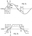
- phase voltages V a , V b and V c across and phase currents I a , I b and I c through windings 20a, 20b and 20c of AC induction motor 12 are identical but for being 120° out of phase with each other. Further, phase currents I a , I b and I c lag the phase voltages V a , V b and V c by an angle ⁇ corresponding to the power factor of AC induction motor 12.
- phase voltage V a across winding 20a is compared to the phase current I a and terminal voltage V T which is the difference in potential between terminals 13d and 13b of AC induction motor 12.
- the waveform of terminal voltage V T is sinusoidal.
- the phase voltage V a is generally identical to the terminal voltage V T except during a small, non-conducting time or notch having a duration ⁇ which is introduced into each half cycle of terminal voltage V T .
- Notch ⁇ is introduced into terminal voltage V T each time phase current I a , falls to zero.
- Phase current I a remains at zero until the end of notch ⁇ at which time phase current I a , continues a pulsating waveform.
- the phase current I a is controlled by the duration of notch ⁇ .
- thyristor switch 22a which interconnects motor terminal 13a and winding 20a operates as an open circuit so that instead of observing sinusoidal terminal voltage V T between motor terminals 13d and 13b, an internal motor generated back EMF voltage may be seen.
- the back EMF voltage is generally equal to the terminal voltage V T minus the voltage drop V ad across thyristor switch 22a.
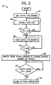
- thyristor switches 22a, 22b and 22c are fired (turned on) after a user selected alpha firing angle ⁇ after the initial zero voltage crosses of corresponding terminal voltages V T .
- the user selected alpha firing angle ⁇ is preferably equally to 135°, block 30. However, other values for the user selected alpha firing angle ⁇ are contemplated as being within the scope of the present invention.
- the alpha firing angle ⁇ is reduced by a predetermined amount and thyristor switches 22a, 22b and 22c are fired again at the reduced alpha firing angle ⁇ after the next zero voltage crosses of corresponding terminal voltages V T .
- the process is repeated for a predetermined period of time, e.g. 2.5 seconds, block 34.
- the alpha firing angle ⁇ is maintained at a selected alpha firing angle ⁇ , block 36, and thyristor switches 22a, 22b and 22c are subsequently fired at such alpha firing angle ⁇ after each zero voltage crosses of corresponding terminal voltages V T for a second predetermined time period, e.g. 8 seconds, block 38.
- a second predetermined time period e.g. 8 seconds
- the phase currents I a , I b and I c of AC induction motor 12 are maintained by maintaining the half cycle time of thyristor switches 22a, 22b and 22c such that the duration of notch ⁇ is maintained until AC induction motor 12 is at full operating speed, block 42.
- the duration of notch ⁇ is maintained at 10°, block 40, but other angles are contemplated as being within the scope of the present invention.
- Full operating speed of AC induction motor 12 may be determined in any conventional manner. For example, by maintaining the phase currents I a , I b and I c of AC induction motor 12 at a predetermined level over a predetermined period of time, the angle ⁇ , Figs.
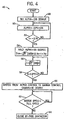
- thyristor switches 22a, 22b and 22c are fired after a user selected alpha firing angle ⁇ , i.e. 135°, block 48, after the initial zero voltage crosses of corresponding terminal voltages V T . Thereafter, the alpha firing angle ⁇ is reduced and thyristor switches 22a, 22b and 22c are fired again at the reduced alpha firing angle ⁇ after the next zero voltage crosses of corresponding terminal voltages V T .
- ⁇ i is the new alpha fring angle
- "-16" and “135" are constants which may be varied according to the application
- t is the elapsed time from the initial firing of thyristor switches 22a, 22b and 22c, block 50. The process is repeated for a predetermined period of time, e.g. 2.5 seconds, block 52.
- the alpha firing angle ⁇ is maintained, block 54, at a selected alpha firing angle ⁇ , e.g. 95°, and thyristor switches 22a, 22b and 22c are subsequently fired at such alpha firing angle ⁇ after each zero voltage crosses of corresponding terminal voltages V T .
- a selected alpha firing angle ⁇ e.g. 95°
- the current limit I lim of AC induction motor 12 is determined.
- phase currents I a , I b and I c of AC induction motor 12 are greater than a predetermined percentage of the current limit I lim of AC induction motor 12, e.g. 0.8 * I lim , the process is repeated and thyristor switches 22a, 22b and 22c are fired again at the selected alpha firing angle ⁇ , block 58. If the phase currents I a , I b and I c of AC induction motor 12 drop below the predetermined percentage of the current limit I lim , the control methodology is changed from alpha control to gamma control, block 60.
- the phase currents I a , I b and I c of AC induction motor 12 are maintained by maintaining the half cycle time of thyristor switches 22a, 22b and 22c such that the duration of notch ⁇ is maintained until AC induction motor 12 is at full operating speed, block 62.
- the duration of notch ⁇ is preferably maintained at 10°, block 60, but other angles are contemplated as being within the scope of the present invention.
- bypass contactors 24a, 24b and 24c are sequentially closed, block 64, such that windings 20a, 20b and 20c are connected directly between corresponding pairs of motor terminals 13a, 13b and 13c.
- thyristor switches 22a, 22b and 22c are initially fired at a user selected alpha firing angle ⁇ , i.e. 135°, block 68, after the initial zero voltage crosses of corresponding terminal voltages V T . Thereafter, a new alpha firing angle ⁇ is calculated based upon the error between the integration of the phase currents I a , I b and I c of AC induction motor 12 and the current limit I lim of AC induction motor 12, block 70.
- k * I - I lim
- Thyristor switches 22a, 22b and 22c are fired again at the new alpha firing angle ⁇ i after the next zero voltage crosses of corresponding terminal voltages V T and the process is repeated until the phase currents I a , I b and I c of AC induction motor 12 drop below a predetermined percentage of the current limit I lim , e.g. 0.8 * I lim , indicating that the AC induction motor 12 is approaching full operating speed, block 74.
- the control methodology is changed from alpha control to gamma control, block 76.
- the half cycle time of thyristor switches 22a, 22b and 22c must be increased.
- ⁇ i ⁇ i ⁇ 1 + k * I ⁇ I lim
- ⁇ i the new gamma firing angle
- ⁇ i -1 the initial gamma firing angle
- k is a proportional gain
- I the integral of the motor current over the previous conduction interval
- I lim is a user selected pre-set current limit, block 78.
- the maximum absolute value of the expression k * ( I - I lim ) be limited to 0.25°, block 78.
- Thyristor switches 22a, 22b and 22c are fired again at the new gamma firing angle ⁇ i after the next zero current crosses of corresponding phase currents I a , I b and I c and the process is repeated until the AC induction motor 12 is at full operating speed, block 80.
- bypass contactors 24a, 24b and 24c are sequentially closed, block 82, such that windings 20a, 20b and 20c are connected directly between corresponding pairs of motor terminals 13a, 13b and 13c.
- a microprocessor (not pictured) carry out a number of predetermined functions which are incorporated into computer executable instructions, Figs. 3-5 . It should be understood that while these functions are described as being implemented in software, it is contemplated that the functions could be implemented in discreet solid state hardware, as well as, the combination of solid state hardware and software.
- the microprocessor will include a plurality of inputs corresponding to selected parameters heretofore described.
- inputs include line voltages V A , V B and V C ; line currents I A , I B and I C ; phase voltages V a, V b and V c ; and phase currents I a , I b and I c .
- the microprocessor generate a plurality of output signals which correspond to selected instructions heretofore described. For example, referring back to Fig.
- microprocessor generates firing signals S A , S B and S C to fire corresponding thyristor switches 22a, 22b, and 22c, respectively, at appropriate times, as heretofore described.
- microprocessor generates firing signals B A , B B and B C to close corresponding bypass contactors 24a, 24b, and 24c, respectively, at appropriate times, as heretofore described.
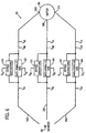
- Motor control system 90 includes an AC induction motor 96 coupled to an AC source 98, as hereinafter described.
- AC induction motor 96 has three windings. Each winding of AC induction motor 96 is operatively connected to a corresponding supply line 100, 102 and 104 from AC source 98 at motor terminals 106, 108 and 110, respectively. Anti-parallel silicon controlled rectifiers (SCRs) or thyristor switches 112, 114, and 116 are also provided. Each thyristor switch 112, 114 and 116 consists of a pair of inversely connected SCRs used to control the voltage on, and the current through, an associated supply line 100, 102 and 104, respectively, which, in turn, alters the current supplied to and the voltage at motor terminals 106, 108, and 110, respectively, of AC induction motor 96.
- SCRs Anti-parallel silicon controlled rectifiers
- thyristor switches 112, 114 and 116 consists of a pair of inversely connected SCRs used to control the voltage on, and the current through, an associated supply line 100, 102 and 104, respectively, which
- terminal voltages V T1 at motor terminals 106, 108 and 110 of AC induction motor 96, the supply voltages V A1 , V B1 and V C1 , and the line currents I A1 , I B1 and I C1 are identical but for being 120° out of phase with each other.
- terminal voltage V AT1 at motor terminal 106 is compared to the line current I A1 and the supply voltage V A1 from AC source 98.
- the waveform of supply voltage V A1 is sinusoidal.
- the terminal voltage V AT1 is generally identical to the supply voltage V A1 except during a small non-conducting time or notch having a duration ⁇ which is introduced into each half cycle of supply voltage V A1 .
- Notch y is introduced into the supply voltage V A1 each time line current I A1 falls to zero.
- Line current I A1 remains at zero until the end of notch ⁇ at which time line current I A1 continues a pulsating waveform.
- the supply line current I A1 is controlled by the duration of notch y.
- thyristor switch 112 which interconnects motor terminal 106 to AC source 98 operates as an open circuit so that instead of observing sinusoidal supply voltage V A1 at motor terminal 106, an internal motor generated back EMF voltage may be seen.
- the back EMF voltage is generally equal to the source voltage V A1 minus the voltage drop V AD1 across thyristor switch 112.
- motor terminal 106 of AC induction motor 96 is connected directly to AC source 98 through supply line 100
- motor terminal 108 of AC induction motor 96 is connected directly AC source 98 through supply line 102
- motor terminal 110 of AC induction motor 96 is connected directly to AC source 98 through supply line 104.
- AC induction motor 96 may be brought to operating speed by providing constant current thereto.
- line current I A1 , I B1 and I C1 lags the supply voltage V A1 , V B1 and V C1 by an angle ⁇ corresponding to the power factor of AC induction motor 96.
- the line currents I A1 , I B1 and I C1 to AC induction motor 16 are maintained by maintaining the conduction period of thyristor switches 112, 114 and 116 such that the duration of notch ⁇ is maintained.
- the angle ⁇ of the power factor of AC induction motor 16 reduces as AC induction motor 96 accelerates and the back EMF voltages at motor terminals 106, 108 and 110 approaches corresponding source voltages V A1 , V B1 and V C1 , respectively.
- Thyristor switches 112, 114 and 116 are initially fired at a user selected initial gamma firing angle gamma, i.e. 55°, block 132, after each zero supply current therethrough.
- a preset current limit I lim , block 132, is selected by the user.
- ⁇ i ⁇ i ⁇ 1 + k * I ⁇ I lim
- ⁇ i the new gamma firing angle
- ⁇ i-1 the initial gamma firing angle
- k the initial gamma firing angle
- I the integral of the motor current over the previous conduction interval
- I lim is a user selected pre-set current limit, block 136.
- the maximum absolute value of the expression k* (I - I lim ) be limited to 0.25°, block 136. Pairs of thyristor switches 112, 114 and 116 are fired again at the new gamma firing angle ⁇ i after the next zero current crossing of corresponding phase currents I a1 , I b1 , I c1 and the process is repeated until the AC induction motor 96 is at full operating speed, block 138. Once the AC induction motor 96 is at full speed, bypass contactors 120, 122 and 124 are sequentially closed, block 140, such that motor terminals 106, 108 and 110 are connected directly to AC source 98.
- Thyristor switches 112,114 and 116 are initially fired at user selected initial alpha firing angle ⁇ , i.e. 135°, block 144, after the initial zero voltage crosses of corresponding terminal voltages V TI .
- a preset current limit I lim , block 144, is selected by the user.
- the maximum absolute value of the expression k*(I-I lim ) be limited to 0.25°, block 148. Pairs of thyristor switches 112, 114 and 116 are fired again at the new alpha firing angle ⁇ i after the next zero voltage crosses of corresponding terminal voltages V T1 and the process is repeated until the AC induction motor 96 is at full operating speed, block 150. Once the AC induction motor 96 is at full speed, bypass contactors 120, 122 and 124 are sequentially closed, block 160, such that motor terminals 106, 108 and 110 are connected directly to AC source 98.
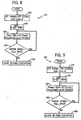
- a microprocessor (not pictured) carry out a number of predetermined functions which are incorporated into computer executable instructions, Figs. 8-9 . It should be understood that while these functions are described as being implemented in software, it is contemplated that the functions could be implemented in discreet solid state hardware, as well as, the combination of solid state hardware and software.
- the microprocessor will include a plurality of inputs corresponding to selected parameters heretofore described.
- inputs include line voltages V A1 , V B1 and V C1 line currents I A1 , I B1 and I C1 phase voltages V a1 , V b1 , and V c1 and phase currents I a1 , I b1 , I c1 .
- the microprocessor generate a plurality of output signals which correspond to selected instructions heretofore described. For example, referring back to Fig.
- microprocessor generates firing signals S A1 , S B1 and S C1 to fire corresponding thyristor switches 112,114, and 116, respectively, at appropriate times, as heretofore described.
- microprocessor generates firing signals B A1 , B B1 and B C1 to close corresponding bypass contactors 120, 122 and 124, respectively, at appropriate times, as heretofore described.
Landscapes
- Engineering & Computer Science (AREA)
- Power Engineering (AREA)
- Control Of Ac Motors In General (AREA)
- Motor And Converter Starters (AREA)
Claims (5)
- Procédé pour commander la tension et le courant fournis à un moteur à courant alternatif (12), le moteur à courant alternatif (12) étant interconnecté à une source d'entrée en courant alternatif (18) par le biais d'un commutateur à thyristors (22a, 22b, 22c), le procédé comprenant les étapes qui consistent :à amorcer initialement le commutateur à thyristors (22a, 22b, 22c) à un angle d'amorçage alpha prédéterminé après une occurrence initiale de tension d'alimentation nulle au niveau d'une borne moteur du moteur à courant alternatif (12) et à prévoir l'angle d'amorçage alpha prédéterminé comme étant un angle d'amorçage alpha initial (αi-1) ;à calculer un nouvel angle d'amorçage alpha (αi) qui dépend de l'angle d'amorçage alpha initial (αi-1) ;à amorcer le commutateur à thyristors (22a, 22b, 22c) au nouvel angle d'amorçage alpha (αi) après une occurrence subséquente de tension d'alimentation nulle au niveau d'une borne moteur (13a, 13b, 13c) du moteur à courant alternatif (12) ; età prévoir le nouvel angle d'amorçage alpha (αi) comme étant l'angle d'amorçage alpha initial (αi-1) ;caractérisé en ce que le nouvel angle d'amorçage alpha est calculé selon l'expression :
 dans laquelle αi est le nouvel angle d'amorçage alpha ; (αi-1) est l'angle d'amorçage alpha initial ; k est un gain proportionnel ; I est une intégrale du courant moteur sur un intervalle de temps de conduction ; et Ilim est une limite de courant préétablie sélectionnée par l'utilisateur.
 - Procédé de la revendication 1, comprenant les étapes supplémentaires qui consistent :à prévoir un contacteur de dérivation (24a, 24b, 24c) en parallèle aux bornes du commutateur à thyristors (22a, 22b, 22c) ;à surveiller la vitesse de fonctionnement du moteur à courant alternatif (12) ; età fermer le contacteur de dérivation (24a, 24b, 24c) en réponse au fonctionnement du moteur à courant alternatif (12) à une vitesse de fonctionnement prédéterminée.
- Procédé de la revendication 1, dans lequel après l'étape d'amorçage du commutateur à thyristors (22a, 22b, 22c) au nouvel angle d'amorçage alpha (αi), réalisant les étapes supplémentaires qui consistent :à surveiller la vitesse de fonctionnement du moteur à courant alternatif (12) et si la vitesse de fonctionnement est inférieure à une vitesse de fonctionnement prédéterminée du moteur à courant alternatif (12), à exécuter l'étape supplémentaire qui consiste à revenir à l'étape de calcul du nouvel angle d'amorçage alpha (αi).
- Procédé de la revendication 1, comprenant les étapes supplémentaires qui consistent à comparer la valeur absolue de l'expression k * (I-Ilim) à une limite de alpha avant de calculer le nouvel angle d'amorçage alpha et à remplacer l'expression k * (I-Ilim) par la limite de alpha dans l'expression pour calculer le nouvel angle d'amorçage alpha si la valeur absolue de l'expression k * (I-Ilim) est supérieure à la limite de alpha.
- Appareil pour commander la tension et le courant fournis à un moteur à courant alternatif (12), le moteur à courant alternatif (12) étant interconnecté à une source d'entrée en courant alternatif (18) par le biais d'un commutateur à thyristors (22a, 22b, 22c), l'appareil comprenant un microprocesseur programmé et configuré pour mettre en oeuvre le procédé de l'une quelconque des revendications précédentes.
Applications Claiming Priority (2)
| Application Number | Priority Date | Filing Date | Title |
|---|---|---|---|
| US09/574,852 US6407529B1 (en) | 2000-05-19 | 2000-05-19 | Method for controlling the starting of an induction motor utilizing closed loop alpha control |
| EP01929849A EP1290781B1 (fr) | 2000-05-19 | 2001-05-18 | Procédé pour contrôler le démarrage d'un moteur à induction à courant alternatif utilisant une commande alpha en boucle fermée |
Related Parent Applications (2)
| Application Number | Title | Priority Date | Filing Date |
|---|---|---|---|
| EP01929849A Division EP1290781B1 (fr) | 2000-05-19 | 2001-05-18 | Procédé pour contrôler le démarrage d'un moteur à induction à courant alternatif utilisant une commande alpha en boucle fermée |
| EP01929849.6 Division | 2001-05-18 |
Related Child Applications (2)
| Application Number | Title | Priority Date | Filing Date |
|---|---|---|---|
| EP10012689.5 Division-Into | 2010-10-01 | ||
| EP10012689 Division-Into | 2010-10-01 |
Publications (3)
| Publication Number | Publication Date |
|---|---|
| EP2192680A2 EP2192680A2 (fr) | 2010-06-02 |
| EP2192680A3 EP2192680A3 (fr) | 2013-02-20 |
| EP2192680B1 true EP2192680B1 (fr) | 2016-04-06 |
Family
ID=24297919
Family Applications (2)
| Application Number | Title | Priority Date | Filing Date |
|---|---|---|---|
| EP01929849A Expired - Lifetime EP1290781B1 (fr) | 2000-05-19 | 2001-05-18 | Procédé pour contrôler le démarrage d'un moteur à induction à courant alternatif utilisant une commande alpha en boucle fermée |
| EP09015163.0A Expired - Lifetime EP2192680B1 (fr) | 2000-05-19 | 2001-05-18 | Procédé de contrôle du démarrage d'un moteur asynchrone en utilisant un contrôle alpha à boucle fermée |
Family Applications Before (1)
| Application Number | Title | Priority Date | Filing Date |
|---|---|---|---|
| EP01929849A Expired - Lifetime EP1290781B1 (fr) | 2000-05-19 | 2001-05-18 | Procédé pour contrôler le démarrage d'un moteur à induction à courant alternatif utilisant une commande alpha en boucle fermée |
Country Status (6)
| Country | Link |
|---|---|
| US (1) | US6407529B1 (fr) |
| EP (2) | EP1290781B1 (fr) |
| AU (1) | AU5652901A (fr) |
| DE (1) | DE60140739D1 (fr) |
| TW (1) | TW522634B (fr) |
| WO (1) | WO2001089072A2 (fr) |
Families Citing this family (10)
| Publication number | Priority date | Publication date | Assignee | Title |
|---|---|---|---|---|
| US6803741B2 (en) * | 2002-09-16 | 2004-10-12 | Rockwell Automation Technologies, Inc. | Motor controller |
| US7006338B2 (en) * | 2002-09-23 | 2006-02-28 | Siemens Energy & Automation, Inc. | System and method for individual phase motor over voltage protection |
| US8084984B2 (en) * | 2008-12-22 | 2011-12-27 | Eaton Corporation | System and method for monitoring and controlling stator winding temperature in a de-energized AC motor |
| EP2499736B1 (fr) | 2009-11-10 | 2014-01-08 | ABB Research Ltd. | Appareil et procede de production d'un couple électromagnétique dans une machine électrique |
| FR2980058B1 (fr) * | 2011-09-13 | 2014-05-09 | Schneider Electric Ind Sas | Procede de commande d'un interrupteur commande pilotant l'alimentation d'un moteur electrique |
| CN103248279A (zh) * | 2013-05-08 | 2013-08-14 | 西安航空学院 | 新型中压软起动器 |
| US10079551B2 (en) * | 2014-05-22 | 2018-09-18 | Ozuno Holdings Limited | Symmetry control circuit of a trailing edge phase control dimmer circuit |
| KR102880728B1 (ko) * | 2021-02-10 | 2025-11-03 | 이턴 인텔리전트 파워 리미티드 | 전력 전자 스위칭 디바이스들을 사용한 모터 소프트 기동기의 제어 |
| CN115441772B (zh) * | 2022-11-07 | 2023-02-07 | 希望森兰科技股份有限公司 | 一种异步电机软起动器触发角控制方法 |
| US12334850B2 (en) * | 2023-09-05 | 2025-06-17 | Eaton Intelligent Power Limited | Control systems and methods for mitigating motor start-up instabilities in lightly loaded conditions near synchronous speed |
Family Cites Families (15)
| Publication number | Priority date | Publication date | Assignee | Title |
|---|---|---|---|---|
| US3991354A (en) | 1975-05-29 | 1976-11-09 | Westinghouse Electric Corporation | Variable speed drive for induction motor |
| US4482853A (en) * | 1981-08-24 | 1984-11-13 | Reuland Electric Company | Composite control for soft start and dynamic braking of a three-phase induction motor |
| US4712054A (en) | 1986-05-14 | 1987-12-08 | East Moline Metal Products Company | Controller with two modes of braking induction motors |
| US4912390A (en) * | 1986-10-16 | 1990-03-27 | Square D Company | Apparatus for controlling firing of thyristors relative to a current reaching zero by using a microcomputer and hardware responsive to voltage crossing zero |
| US4796142A (en) | 1986-10-16 | 1989-01-03 | Square D Company | Overload protection apparatus for emulating the response of a thermal overload |
| JPS63204307A (ja) | 1987-02-19 | 1988-08-24 | Fanuc Ltd | 過電流検出装置 |
| US5008608A (en) * | 1989-12-26 | 1991-04-16 | Allen-Bradley Company, Inc. | Controller for starting and stopping electric motors |
| US4996469A (en) * | 1990-03-16 | 1991-02-26 | Allen-Bradley Company, Inc. | Electric motor controller with bypass contactor |
| US4978897A (en) * | 1990-04-26 | 1990-12-18 | Allen-Bradley Company, Inc. | Motor controller with an improved stopping technique |
| US5151642A (en) * | 1990-05-03 | 1992-09-29 | Allen-Bradley Company, Inc. | Apparatus for controlling an electric motor |
| US5305234A (en) | 1991-12-31 | 1994-04-19 | Westinghouse Electric Corp. | Thermal protection apparatus for a synchronous machine |
| US5568753A (en) * | 1993-02-17 | 1996-10-29 | G. Lyle Habermehl | Screw driver with replaceable nose for collated screws |
| JPH10337063A (ja) * | 1997-06-05 | 1998-12-18 | Hirohito Sato | 交流電動機の始動方法及び装置 |
| US6160365A (en) * | 1999-03-11 | 2000-12-12 | Eaton Corporation | Interface module for a motor control system |
| US6163129A (en) * | 1999-03-11 | 2000-12-19 | Eaton Corporation | Method of controlling the starting, stopping and speed of an AC induction motor |
-
2000
- 2000-05-19 US US09/574,852 patent/US6407529B1/en not_active Expired - Lifetime
-
2001
- 2001-05-11 TW TW090111268A patent/TW522634B/zh not_active IP Right Cessation
- 2001-05-18 EP EP01929849A patent/EP1290781B1/fr not_active Expired - Lifetime
- 2001-05-18 WO PCT/GB2001/002179 patent/WO2001089072A2/fr not_active Ceased
- 2001-05-18 AU AU56529/01A patent/AU5652901A/en not_active Abandoned
- 2001-05-18 EP EP09015163.0A patent/EP2192680B1/fr not_active Expired - Lifetime
- 2001-05-18 DE DE60140739T patent/DE60140739D1/de not_active Expired - Lifetime
Also Published As
| Publication number | Publication date |
|---|---|
| DE60140739D1 (de) | 2010-01-21 |
| EP2192680A2 (fr) | 2010-06-02 |
| AU5652901A (en) | 2001-11-26 |
| WO2001089072A3 (fr) | 2002-03-28 |
| TW522634B (en) | 2003-03-01 |
| EP1290781A2 (fr) | 2003-03-12 |
| US6407529B1 (en) | 2002-06-18 |
| EP2192680A3 (fr) | 2013-02-20 |
| EP1290781B1 (fr) | 2009-12-09 |
| WO2001089072A2 (fr) | 2001-11-22 |
Similar Documents
| Publication | Publication Date | Title |
|---|---|---|
| EP0435038B1 (fr) | Régulateur pour démarrer et arrêter des moteurs électriques | |
| EP1282937B1 (fr) | Procede de commande du demarrage d'un moteur a induction ca | |
| US6420848B1 (en) | Method and controlling the starting of an AC induction motor with closed loop current control | |
| US5012172A (en) | Control system for switched reluctance motor operating as a power generator | |
| EP2192680B1 (fr) | Procédé de contrôle du démarrage d'un moteur asynchrone en utilisant un contrôle alpha à boucle fermée | |
| JPH0612954B2 (ja) | 同期電動機の制御方法 | |
| US6930459B2 (en) | Method for reducing the influence of a DC current component in the load current of an asynchronous motor | |
| EP2062347B1 (fr) | Procede et dispositif de reduction de l'influence d'une composante continue dans un courant de charge d'un moteur asynchrone triphase | |
| US11128240B1 (en) | Reduced voltage soft starter apparatus and methods using current-controlled transitions | |
| JP3148230B2 (ja) | 単相または多相交流調整器の制御方法および装置 | |
| RU2277289C1 (ru) | Способ квазичастотного мягкого пуска синхронного двигателя и устройство для его осуществления | |
| Mestry et al. | Smooth starting of induction motor during open circuit and short circuit condition | |
| RU2014720C1 (ru) | Способ пуска и самозапуска синхронного двигателя | |
| US6667596B1 (en) | Method and device for controlling deceleration in an induction machine | |
| EP2011225A1 (fr) | Commande de moteur | |
| Jangid et al. | Soft Starter for Induction Motor | |
| JP2000014197A (ja) | 同期発電機の同期化装置及びその同期投入方法 | |
| RU47149U1 (ru) | Устройство плавного пуска высоковольтного электродвигателя | |
| JPH1042590A (ja) | 電圧形インバータ | |
| SU1577028A2 (ru) | Однофазный тиристорный инвертор напр жени | |
| RU1774453C (ru) | Способ пуска асинхронного электродвигател и устройство дл его осуществлени | |
| JPH0548599U (ja) | 同期機の脱調防止装置 | |
| JPH08182386A (ja) | 交流電動機の制御装置 | |
| SU1274104A1 (ru) | Способ пуска асинхронного двигател с фазным ротором и устройство дл его осуществлени | |
| JPH08242583A (ja) | インバータの制御装置 |
Legal Events
| Date | Code | Title | Description |
|---|---|---|---|
| PUAI | Public reference made under article 153(3) epc to a published international application that has entered the european phase |
Free format text: ORIGINAL CODE: 0009012 |
|
| AC | Divisional application: reference to earlier application |
Ref document number: 1290781 Country of ref document: EP Kind code of ref document: P |
|
| AK | Designated contracting states |
Kind code of ref document: A2 Designated state(s): DE FR GB |
|
| PUAL | Search report despatched |
Free format text: ORIGINAL CODE: 0009013 |
|
| AK | Designated contracting states |
Kind code of ref document: A3 Designated state(s): DE FR GB |
|
| RIC1 | Information provided on ipc code assigned before grant |
Ipc: H02P 1/28 20060101ALI20130116BHEP Ipc: H02P 1/26 20060101AFI20130116BHEP |
|
| 17P | Request for examination filed |
Effective date: 20130820 |
|
| RBV | Designated contracting states (corrected) |
Designated state(s): DE FR GB |
|
| 17Q | First examination report despatched |
Effective date: 20140122 |
|
| GRAP | Despatch of communication of intention to grant a patent |
Free format text: ORIGINAL CODE: EPIDOSNIGR1 |
|
| INTG | Intention to grant announced |
Effective date: 20150304 |
|
| GRAS | Grant fee paid |
Free format text: ORIGINAL CODE: EPIDOSNIGR3 |
|
| GRAP | Despatch of communication of intention to grant a patent |
Free format text: ORIGINAL CODE: EPIDOSNIGR1 |
|
| INTG | Intention to grant announced |
Effective date: 20151007 |
|
| GRAA | (expected) grant |
Free format text: ORIGINAL CODE: 0009210 |
|
| AC | Divisional application: reference to earlier application |
Ref document number: 1290781 Country of ref document: EP Kind code of ref document: P |
|
| AK | Designated contracting states |
Kind code of ref document: B1 Designated state(s): DE FR GB |
|
| REG | Reference to a national code |
Ref country code: GB Ref legal event code: FG4D |
|
| REG | Reference to a national code |
Ref country code: DE Ref legal event code: R096 Ref document number: 60149865 Country of ref document: DE |
|
| REG | Reference to a national code |
Ref country code: DE Ref legal event code: R119 Ref document number: 60149865 Country of ref document: DE |
|
| PLBE | No opposition filed within time limit |
Free format text: ORIGINAL CODE: 0009261 |
|
| STAA | Information on the status of an ep patent application or granted ep patent |
Free format text: STATUS: NO OPPOSITION FILED WITHIN TIME LIMIT |
|
| REG | Reference to a national code |
Ref country code: FR Ref legal event code: ST Effective date: 20170131 |
|
| 26N | No opposition filed |
Effective date: 20170110 |
|
| GBPC | Gb: european patent ceased through non-payment of renewal fee |
Effective date: 20160706 |
|
| PG25 | Lapsed in a contracting state [announced via postgrant information from national office to epo] |
Ref country code: DE Free format text: LAPSE BECAUSE OF NON-PAYMENT OF DUE FEES Effective date: 20161201 Ref country code: FR Free format text: LAPSE BECAUSE OF NON-PAYMENT OF DUE FEES Effective date: 20160606 |
|
| PG25 | Lapsed in a contracting state [announced via postgrant information from national office to epo] |
Ref country code: GB Free format text: LAPSE BECAUSE OF NON-PAYMENT OF DUE FEES Effective date: 20160706 |