EP2192793A1 - Lautsprecher - Google Patents
Lautsprecher Download PDFInfo
- Publication number
- EP2192793A1 EP2192793A1 EP08857198A EP08857198A EP2192793A1 EP 2192793 A1 EP2192793 A1 EP 2192793A1 EP 08857198 A EP08857198 A EP 08857198A EP 08857198 A EP08857198 A EP 08857198A EP 2192793 A1 EP2192793 A1 EP 2192793A1
- Authority
- EP
- European Patent Office
- Prior art keywords
- space
- voice coil
- edge
- speaker
- coil body
- Prior art date
- Legal status (The legal status is an assumption and is not a legal conclusion. Google has not performed a legal analysis and makes no representation as to the accuracy of the status listed.)
- Withdrawn
Links
Images


Classifications
-
- H—ELECTRICITY
- H04—ELECTRIC COMMUNICATION TECHNIQUE
- H04R—LOUDSPEAKERS, MICROPHONES, GRAMOPHONE PICK-UPS OR LIKE ACOUSTIC ELECTROMECHANICAL TRANSDUCERS; ELECTRIC HEARING AIDS; PUBLIC ADDRESS SYSTEMS
- H04R9/00—Transducers of moving-coil, moving-strip, or moving-wire type
- H04R9/02—Details
- H04R9/04—Construction, mounting, or centering of coil
- H04R9/041—Centering
- H04R9/043—Inner suspension or damper, e.g. spider
-
- H—ELECTRICITY
- H04—ELECTRIC COMMUNICATION TECHNIQUE
- H04R—LOUDSPEAKERS, MICROPHONES, GRAMOPHONE PICK-UPS OR LIKE ACOUSTIC ELECTROMECHANICAL TRANSDUCERS; ELECTRIC HEARING AIDS; PUBLIC ADDRESS SYSTEMS
- H04R2201/00—Details of transducers, loudspeakers or microphones covered by H04R1/00 but not provided for in any of its subgroups
- H04R2201/34—Directing or guiding sound by means of a phase plug
-
- H—ELECTRICITY
- H04—ELECTRIC COMMUNICATION TECHNIQUE
- H04R—LOUDSPEAKERS, MICROPHONES, GRAMOPHONE PICK-UPS OR LIKE ACOUSTIC ELECTROMECHANICAL TRANSDUCERS; ELECTRIC HEARING AIDS; PUBLIC ADDRESS SYSTEMS
- H04R2400/00—Loudspeakers
- H04R2400/11—Aspects regarding the frame of loudspeaker transducers
Definitions
- the present invention relates to a speaker.
- FIG. 5 is a sectional view of a conventional speaker.
- the conventional speaker includes voice coil body 504 with coil part 503 movably disposed in magnetic gap 502 formed by magnetic circuit body 501; diaphragm 508 connected to the outer circumferential surface of voice coil bobbin 505 of voice coil body 504 and connected to frame 507 through edge 506; and corrugated damper 509 placed closer to magnetic circuit body 501 than from diaphragm 508, connected to the outer circumferential surface of voice coil bobbin 505 and to frame 507.
- voice coil body 504 Passing an AC current with a sound signal added thereto through coil part 503 of voice coil body 504 causes voice coil body 504 to vibrate vertically. The vertical vibration of voice coil body 504 is transmitted to diaphragm 508, which vibrates air to reproduce sound.
- damper 509 supports voice coil body 504 together with a complex of diaphragm 508 and edge 506, and follows vibration of voice coil body 504 by means of the corrugated structure expanding and contracting during sound reproduction.
- Information on prior art documents related to the patent application includes FIG. 8 in patent literature 1.
- the Young's modulus of damper 109 needs to be high (rigid) to some extent in order to support voice coil body 104.
- the high Young's modulus of damper 509 vertical amplitude of voice coil body 504 higher than a certain level during sound reproduction rapidly increases the movable load, which makes it difficult for voice coil body 504 to vibrate faithfully according to an input signal. Consequently, the speaker creates distortion during sound reproduction.
- FIG. 6 is a sectional view of another conventional speaker.
- the speaker includes voice coil body 603 with the coil part movably disposed in magnetic gap 602 formed by magnetic circuit body 601; diaphragm 606 connected to the outer circumferential surface of the voice coil bobbin of voice coil body 603 and connected to frame 605 through first edge 604; and damper 608 placed closer to magnetic circuit body 601 than from voice coil body 603, connected to the side surface of voice coil body 603, and connected to frame 605 through second edge 607.
- First edge 604 projects in the direction opposite to that of second edge 607 to make vertical amplitude of diaphragm 606 symmetric, thereby reducing distortion with the speaker.
- patent literature 2 information on prior art documents related to the patent application includes patent literature 2.
- first edge 604 is preferably nearly equal to that of a complex formed of damper 8 and second edge 607.
- first edge 604 and a complex formed of damper 608 and second edge 607 need enough rigidity to support voice coil body 603 and have a high Young's modulus, and thus first edge 604 unlikely deforms following vertical amplitude of voice coil body 603. Consequently, diaphragm 606 connected to first edge 604 deforms during sound reproduction, causing disturbance in frequency response in the middle and high ranges.
- first edge 604 requires reducing that of the complex formed of damper 608 and second edge 607 as well. This is because the Young's modulus of first edge 604 is preferably nearly equal to that of the complex.
- first edge 604 and the complex formed of damper 608 and second edge 607, with their Young's moduli thus reduced, are unable to well support voice coil body 603.
- the present invention reduces distortion during sound reproduction by a speaker.
- a speaker includes a frame; a magnetic circuit body supported by the frame; a voice coil body with its coil part movably disposed in a magnetic gap formed by the magnetic circuit body; a dust cap provided so as to block the opening of the voice coil bobbin of the voice coil body; a diaphragm having an inner circumference connected to the outer circumferential surface of the voice coil bobbin of the voice coil body; a first edge having an inner circumferential end connected to the outer circumference of the diaphragm, having an outer circumferential end connected to the frame; and a connecting member placed closer to the magnetic circuit body than from the diaphragm, having an inner circumferential end connected to the outer circumferential surface of the voice coil bobbin of the voice coil body, and having an outer circumferential end connected to the frame.
- the speaker has a first space airtight to the atmosphere outside the speaker, functioning as an air suspension, where the first space is enclosed by the surface of the connecting member close to the magnetic circuit body, the outer circumferential surface of the voice coil body, the magnetic circuit body, and the frame.
- FIG. 1 is a sectional view of the speaker according to the first embodiment of the present invention.
- the speaker according to the present invention supports the voice coil body, additionally with the first edge and the second edge (i.e. connecting members), with the aid of the springiness of gas inside the space enclosed by the surface of the second edge close to the magnetic circuit body, suspension holder, outer circumferential surface of the voice coil body, magnetic circuit body, and frame.
- this structure allows reducing a load exerted on the first and second edges to support the voice coil body.
- this structure can support the voice coil body.
- the diaphragm connected to the first edge is less likely to deform during sound reproduction, thereby reducing disturbance in frequency response in the middle and high ranges.
- Frame 9 of the speaker according to the first embodiment has a shape formed by overlaying bottomed, cylinder-shaped lower frame part 9a onto bottomed, dish-shaped upper frame part 9b with a diameter larger than that of part 9a.
- Upper frame part 9b is provided therein with openings 9c communicating with outside air.
- Magnetic circuit body 10 is placed in the center of the bottom of lower frame part 9a and is formed by bonding disk-shaped plate 10a, disk-shaped magnet 10b, and cylinder-shaped yoke 10c in combination. Magnetic circuit body 10 forms cylinder-shaped magnetic gap 11 from the outer circumferential surface of plate 10a toward the inner circumferential surface of yoke 10c.
- Voice coil body 12 is formed of cylinder-shaped voice coil bobbin 12a and coil 12b wound around the outer circumferential surface of voice coil bobbin 12a, where coil 12b is disposed movably with respect to magnetic gap 11.
- hemispherical dust cap 13 is disposed connecting to diaphragm 15 so as to cover the upper opening of voice coil bobbin 12a, thereby preventing dust and moisture from ingressing into magnetic gap 11 through the upper opening of voice coil body 12.
- fine braided wire 14 of coil 12b is drawn out from the upper part of voice coil body 12 to the outside of frame 9.
- Diaphragm 15 is cone-shaped and its inner circumference is connected to the outer circumferential surface of voice coil body 12. Diaphragm 15 generates sound by vertically vibrating during sound reproduction by the speaker, containing mainly pulp and resin balancing high rigidity with low internal loss.
- first edge 16 is connected to the outer circumference of diaphragm 15, and first edge 16 is formed of a material such as urethane foam resin, foamed rubber, and SBR rubber so as not to exert a movable load on diaphragm 15 during sound reproduction. Further, the outer circumferential end of first edge 16 is connected to the vicinity of the top end of the inner circumferential surface of upper frame part 9b, supported by frame 9.
- Second edge 17 as a connecting member is disposed closer to magnetic circuit body 10 than from diaphragm 15.
- the inner circumferential end of second edge 17 is connected to the outer circumferential surface of voice coil bobbin 12a through suspension holder 18 as a connecting member, and the outer circumferential end of second edge 17 is connected to frame 9.
- First edge 16 and second edge 17 are symmetric and similar in shape to each other as shown in FIG. 1 .
- first edge 16 is semicircular in cross section projecting upward
- second edge 17 is semicircular in cross section projecting toward magnetic circuit body 10 (i.e. the opposite direction).
- first edge 16 and second edge 17 have a nearly equivalent Young's modulus.
- first edge 16 and second edge 17 are shaped so as to project in the direction opposite to each other, and their Young's moduli are nearly equivalent, vertical movable loads exerted by voice coil body 12 on first edge 16 and second edge 17 are approximately equal to each other.
- the speaker of the first embodiment can be symmetric in vertical movability of diaphragm 15, reducing distortion contained in sound reproduced.
- nonlinearity and/or asymmetry of a movable load on the damper contribute to distortion generated during sound reproduction by the speaker, and thus a damper is eliminated in the speaker of the first embodiment.
- space 19 is enclosed by first edge 16, diaphragm 15, voice coil body 12, the top surface of suspension holder 18, the top surface of second edge 17, and upper frame part 9b; and space 20 is enclosed by the surface of second edge 17 close to the magnetic circuit body 10, the bottom surface of suspension holder 18, the outer circumferential surface of voice coil body 12, yoke 10c (part of magnetic circuit body 10), and lower frame part 9a.
- communication space 19 is formed by first edge 16, diaphragm 15, voice coil body 12, the top surface of suspension holder 18, the top surface of second edge 17, and upper frame part 9b.
- upper frame part 9b is provided therein with openings 9c, and thus communication space 19 communicates with outside air.
- first space 20 is not provided with an opening at lower frame part 9a, and thus does not communicate with outside air. In other words, first space 20 does not leak air to the outside of frame 9 and is airtight to the atmosphere outside the speaker.
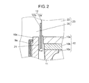
- FIG. 2 is an enlarged view of magnetic gap 11 of the speaker according to the first embodiment of the present invention.
- voice coil body 12 is inserted so as not to contact plate 10a or yoke 10c, thus making slight gap 21 between plate 10a and yoke 10c.
- gas inside first space 20 may move into and out of second space 22 formed by dust cap 13, voice coil body 12, plate 10a (part of magnetic circuit body 10), and diaphragm 15 through gap 21.
- second space 22 is not provided with an opening for communicating with outside air, and thus second space 22 does not leak air to the outside of the speaker.
- First space 20 and second space 22 are hermetically sealed and airtight to the atmosphere outside the speaker.
- An AC current with a sound signal added thereto when passed through voice coil body 12 of speaker structured as described above, reacts with magnetic gap 11 formed by magnetic circuit body 10, generating a driving force at voice coil body 12.
- the driving direction is determined by Fleming's left hand rule, and voice coil body 12 fluctuates vertically.
- the fluctuation of voice coil body 12 causes diaphragm 15 connected to voice coil body 12 to vibrate, which moves air to make the speaker generate sound.
- first edge 16 and second edge 17 are structured to support voice coil body 12, and thus normally it is desirable to set a high Young's modulus to first edge 16 and second edge 17 to raise their rigidity.
- first space 20 enclosed by the surface of second edge 17 (i.e. connecting member) close to magnetic circuit body 10, suspension holder 18, the outer circumferential surface of voice coil body 12, magnetic circuit body 10, and frame 9 is made airtight to the atmosphere outside the speaker.
- gas inside first space 20 functions as a spring
- first space 20 functions as an air suspension. Consequently, voice coil body 12 is supported with first edge 16 and second edge 17, and with the aid of the springiness of first space 20, which reduces a load exerted on first edge 16 and second edge 17.
- first edge 16 and second edge 17 a nearly equivalent, low Young's modulus can be set to first edge 16 and second edge 17.
- First edge 16 with a low Young's modulus thus being set thereto follows vertical amplitude of voice coil body 12 to deform suitably, which decreases deformation of diaphragm 15 connected to the first edge, thereby reducing disturbance in frequency response in the middle and high ranges.
- first space 20 communicates with second space 22 through gap 21.
- second space 22, similarly to first space 20, is airtight to the atmosphere outside the speaker.
- first space 20 and the space communicating with first space 20 are made function as an air suspension.
- second space 22 is made airtight to the atmosphere, and the space of first space 20 and second space 22 combined is made hermetically sealed, and second space 22, in addition to first space 20, is made function as an air suspension.
- the outer circumferential end of dust cap 13 is connected to diaphragm 15.
- another configuration provides the same effect. That is, the outer circumferential end of dust cap 13 is connected to the top end of voice coil bobbin 12a; and second space 22 is formed by dust cap 13, voice coil body 12, and plate 10a (part of magnetic circuit body 10).
- second edge 17 has a shape projecting in the direction opposite to diaphragm 15, and first edge 16 has a shape projecting in the direction opposite to second edge 17.
- first edge 16 and second edge 17 are provided so as to project in the direction opposite to each other, diaphragm 15 is unlikely to fluctuate to one side or the other compared to a case of the same direction, resulting in symmetry, which reduces distortion during sound reproduction.
- first edge 16 and second edge 17 made symmetric and similar in shape to each other, vertical fluctuation of diaphragm 15 becomes more symmetric, which further reduces distortion during sound reproduction.
- an adhesive containing modified silicone is desirably used.
- first space 20 is formed by bonding together each material of frame 9, second edge 17, suspension holder 18, and voice coil body 12 with an adhesive. To make first space 20 adequately function as an air suspension, air leakage from the bonded parts to the outside of the speaker needs to be minimized.
- an adhesive containing modified silicone is desirably used.
- an adhesive used primarily containing modified silicone to bond together each material of dust cap 13, diaphragm 15, and voice coil body 12 forming second space 22 in the present invention the possibility of air leakage is reduced from the bonded parts to the outside of the speaker, which further increases the sealing performance of the space formed by first space 20 and second space 22. Consequently, gas inside the space formed by first space 20 and second space 22 achieves a higher degree of springiness.
- Upper frame part 9b between first edge 16 and second edge 17 is desirably provided therein with opening 9c.
- the reason is the following.
- the speaker of the first embodiment has first space 20 hermetically sealed. If communication space 19 is also hermetically sealed in this state, all the spaces enclosed by diaphragm 15 and frame 9 result in a hermetically sealed structure. Consequently, the springiness of the space enclosed by diaphragm 15 and frame 9 suppresses vertical vibration of diaphragm 15 during sound reproduction.
- a damper is eliminated for reducing distortion contained during sound reproduction by the speaker.
- a space enclosed by the second edge surface close to the magnetic circuit body, damper, outer circumferential surface of the voice coil body, magnetic circuit body, and frame can be made airtight to the atmosphere outside the speaker, if the damper is formed of a gas-blocking material, which provides the same advantages as the first embodiment.
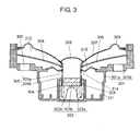
- FIG. 3 is a sectional view of the speaker according to the second embodiment of the present invention.
- the speaker according to the second embodiment of the present invention includes an air-impermeable sealing member as a connecting member instead of a damper in a conventional speaker.
- the speaker is structured so that a first space and a second space are airtight to the atmosphere outside the speaker.
- the first space is enclosed by the sealing member surface close to the magnetic circuit body, outer circumferential surface of the voice coil body, magnetic circuit body, and frame.
- the second space communicates with the first space and is enclosed by the dust cap, inner circumferential surface of the voice coil body, and magnetic circuit body; or by the diaphragm, dust cap, inner circumferential surface of the voice coil body, and magnetic circuit body.
- an air-impermeable sealing member hermetically seals gas inside the first and second spaces, which functions as a spring to support the voice coil body with a complex formed of the diaphragm and edge, as well as with the aid of the springiness of gas inside the first and second spaces.
- the voice coil body can be supported without a damper (i.e. a movable load on the voice coil body) provided. Consequently, the amplitude of the voice coil body is not restricted by a damper, unlike with a conventional speaker, but the voice coil body faithfully vibrates according to a signal input, and thus the speaker of the present invention reduces distortion during sound reproduction.
- a damper i.e. a movable load on the voice coil body
- Frame 301 of the speaker according to the second embodiment has a shape formed by overlaying bottomed, cylinder-shaped lower frame part 301a onto bottomed, dish-shaped upper frame part 301b with a diameter larger than that of lower frame part 301a.
- Upper frame part 301b is provided therein with openings 302 communicating with outside air.
- Magnetic circuit body 303 is placed in the center of the bottom of lower frame part 301a and is formed by bonding disk-shaped plate 303a, disk-shaped magnet 303b, and cylinder-shaped yoke 303c in combination. Magnetic circuit body 303 forms cylinder-shaped magnetic gap 304 between the outer circumferential surface of plate 303a and the inner circumferential surface of yoke 303c.
- Voice coil body 305 is formed of cylinder-shaped voice coil bobbin 305a and coil 305b wound around the outer circumferential surface of voice coil bobbin 305a, where coil 305b is disposed movably with respect to magnetic gap 304.
- hemispherical dust cap 306 is disposed connecting to diaphragm 307 so as to cover the upper opening of voice coil bobbin 305a, thereby preventing dust and moisture from ingressing into magnetic gap 304 through the upper opening of voice coil body 305 and preventing a malfunction of the speaker.
- fine braided wire 308 connected to coil 305b is drawn out from the upper part of voice coil body 305 to the outside of frame 301. Through fine braided wire 308, an AC current with a sound signal added thereto is passed from the outside of the speaker to coil 305b.
- Diaphragm 307 is cone-shaped and its inner circumference is connected to the outer circumferential surface near the top end of voice coil body 305, and its outer circumference is connected to the vicinity of the top end of the inner circumferential surface of upper frame part 301b through first edge 309 with a shape projecting upward. Diaphragm 307 generates sound by vertically vibrating during sound reproduction by the speaker, containing mainly pulp and resin balancing high rigidity with low internal loss.
- first edge 309 has a shape projecting upward so as not to exert a movable load on voice coil body 305 during sound reproduction by the speaker and is formed of a material such as urethane foam resin, foamed rubber, SBR rubber, and cloth.
- Sealing member 310 as a connecting member has a ring-shaped flat surface and a nearly S-shaped cross section.
- the inner circumference of sealing member 310 is connected to voice coil bobbin 305a between fine braided wire 308 and coil 305b, and the outer circumference is connected to frame 301.
- Sealing member 310 is made of a material with high elasticity and flexibility, and with air impermeability, where such as a rubber-based material and vinyl material is preferable. Besides, an appropriate material coated with rubber for air impermeability may be used.
- sealing member 310 has high elasticity and flexibility only around the frame 301 junction and voice coil bobbin 305a junction, and at the nearly S-shaped projections, shown by the dotted-line circles in FIG. 3 , while the other portions are formed being close to a rigid body.
- sealing member 310 is not uniformly elastic or flexible, that is some parts are higher in elasticity and flexibility than others. With such a structure, the parts marked by the dotted-line circles deform while voice coil body 305 is vibrating to allow sealing member 310 to follow vibration of voice coil body 305.
- the reason why the parts not marked by the dotted-line circles are formed being close to a rigid body is to efficiently receive an air pressure exerted by a hermetically closed space (described later) to make the space effectively function as an air suspension.
- sealing member 310 having uniform, high elasticity and flexibility does not withstand an air pressure exerted from the hermetically closed space while voice coil body 305 is vibrating, disabling sealing member 310 to maintain an appropriate shape.
- the parts not marked by the dotted-line circles are formed being close to a rigid body to enable sealing member 310 to maintain an appropriate shape while voice coil body 305 is vibrating, thereby making the hermetically closed space effectively function as an air suspension.
- relatively low elasticity and flexibility are set to the parts shown by the dotted-line circles in FIG. 3 as described above.
- the present invention is not limited to the setting, but low elasticity and flexibility may be set to only the vicinity of the frame 301 junction and voice coil bobbin 305a junction, for instance.
- sealing member 310 Next, a description is made of a hermetically closed space formed by sealing member 310.
- first space 311 enclosed by the surface of sealing member 310 close to magnetic circuit body 303, the outer circumferential surface of voice coil body 305, yoke 303c (part of magnetic circuit body 303), and lower frame part 301a does not communicate with outside air, and is airtight to the atmosphere outside the speaker.
- frame 301 provided therein with opening 302 communication space 312 enclosed by first edge 309, diaphragm 307, voice coil body 305, the top surface of sealing member 310, and upper frame part 301b communicates with the atmosphere outside the speaker.
- sealing member 310 stops gas from moving between first space 311 and communication space 312, preventing gas inside first space 311 from leaking to the atmosphere outside the speaker.
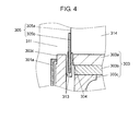
- FIG. 4 is an enlarged view of magnetic gap 304 of the speaker according to the second embodiment of the present invention.
- coil 305b of voice coil body 305 is inserted into magnetic gap 304 so as not to contact plate 303a or yoke 303c in the second embodiment, and thus making slight gap 313 between coil 305b and plate 303a, and between coil 305b and yoke 303c.
- gas inside first space 311 may move through gap 313 into and out of second space 314 formed from dust cap 306, voice coil body 305, plate 303a (part of magnetic circuit body 303), and diaphragm 307.
- an opening is not provided for making second space 314 communicate with outside air, and thus air does not leak from second space 314 to the outside of the speaker.
- first space 311 and second space 314 are airtight to the atmosphere outside the speaker.
- An AC current with a sound signal added thereto when passed through voice coil body 305b of the speaker structured as described above, reacts with magnetic gap 304 formed by magnetic circuit body 303, generating a driving force at voice coil body 305.
- the driving direction is determined by Fleming's left hand rule, and voice coil body 305 vibrates vertically.
- the vibration of voice coil body 305 causes diaphragm 307 connected to voice coil body 305 to vibrate, which moves air to make the speaker reproduce sound.
- a corrugated damper is connected to the voice coil body to make it easy to follow vibration of the voice coil body during sound production by the speaker.
- vibration of the voice coil body larger than a given level prevents the damper from completely following the vibration, rapidly increasing a movable load on the voice coil body, which makes it difficult for the voice coil body to vibrate faithfully according to an input signal. Consequently, as long as the voice coil body is supported with the damper, sound reproduced by the speaker results in containing distortion.
- sealing member 310 is provided instead of a damper and is air-impermeable.
- First space 311 and second space 314 are airtight to the atmosphere outside the speaker, where first space 311 is enclosed by the surface of sealing member 310 close to magnetic circuit body 303, the outer circumferential surface of voice coil body 305, yoke 303c (part of magnetic circuit body 303), and lower frame part 301a; second space 314 is enclosed by dust cap 306, voice coil body 305, plate 303a (part of magnetic circuit body 303), and diaphragm 307.
- first space 311 and second space 314 being thus airtight to the atmosphere outside the speaker, gas inside first space 311 and second space 314 exhibits a function as a spring, and first space 311 and second space 314 function as an air suspension. Consequently, in the second embodiment, without a damper provided, unlike in a conventional speaker, voice coil body 305 is adequately supported with a complex of first edge 309 and diaphragm 307, and with the aid of the springiness of first space 311 and second space 314.
- sealing member 310 has high flexibility and elasticity at the parts marked by the dotted-line circles in FIG. 3 , and thus sealing member 310 does not restrain voice coil body 305 from vibrating vertically during sound reproduction by the speaker, and sealing member 310 does not exert a movable load on voice coil body 305, unlike with a conventional speaker.
- voice coil body 305 vibrates faithfully according to an input signal, thereby reducing distortion contained during sound reproduction by the speaker.
- the outer circumferential end of dust cap 306 is connected to diaphragm 307, and second space 314 is a space enclosed by diaphragm 307, dust cap 306, voice coil body 305, and magnetic circuit body 303.
- second space 314 is a space enclosed by diaphragm 307, dust cap 306, voice coil body 305, and magnetic circuit body 303.
- another configuration provides the same effect. That is, the outer circumferential end of dust cap 306 is connected to the top end of voice coil bobbin 305a; and second space 314 is formed by dust cap 306, voice coil body 305, and plate 303a (part of magnetic circuit body 303).
- an adhesive containing modified silicone is desirably used.
- first space 311 is formed by bonding together each material of sealing member 310, voice coil body 305, magnetic circuit body 303, and frame 301 with an adhesive. To make first space 311 adequately function as an air suspension, air leakage from the bonded parts to the outside of the speaker needs to be minimized.
- an adhesive containing modified silicone is desirably used.
- an adhesive used primarily containing modified silicone to bond together each material of dust cap 306, diaphragm 307, and voice coil body 305 forming second space 314 in the present invention the possibility of air leakage is reduced from the bonded parts to the outside of the speaker, which results in a higher degree of springiness of gas inside the space formed of first space 311 and second space 314.
- a speaker according to the present invention enables supporting the voice coil body with a complex of the diaphragm and edge, and a connecting member, with the aid of gas springiness. More specifically, the speaker according to the present invention does not include a damper that causes a movable load on the voice coil body, to allow the voice coil body to vibrate faithfully according to an input signal, thereby reducing distortion contained during sound reproduction by the speaker. Hence, the present invention is suitably applicable to various types of audio equipment.
Landscapes
- Physics & Mathematics (AREA)
- Engineering & Computer Science (AREA)
- Acoustics & Sound (AREA)
- Signal Processing (AREA)
- Audible-Bandwidth Dynamoelectric Transducers Other Than Pickups (AREA)
- Diaphragms For Electromechanical Transducers (AREA)
Applications Claiming Priority (3)
| Application Number | Priority Date | Filing Date | Title |
|---|---|---|---|
| JP2007312105A JP2009135858A (ja) | 2007-12-03 | 2007-12-03 | スピーカ |
| JP2008062164A JP5167874B2 (ja) | 2008-03-12 | 2008-03-12 | スピーカ |
| PCT/JP2008/003570 WO2009072275A1 (ja) | 2007-12-03 | 2008-12-03 | スピーカ |
Publications (2)
| Publication Number | Publication Date |
|---|---|
| EP2192793A1 true EP2192793A1 (de) | 2010-06-02 |
| EP2192793A4 EP2192793A4 (de) | 2014-07-23 |
Family
ID=40717457
Family Applications (1)
| Application Number | Title | Priority Date | Filing Date |
|---|---|---|---|
| EP08857198.9A Withdrawn EP2192793A4 (de) | 2007-12-03 | 2008-12-03 | Lautsprecher |
Country Status (4)
| Country | Link |
|---|---|
| US (1) | US8351642B2 (de) |
| EP (1) | EP2192793A4 (de) |
| CN (2) | CN102917295A (de) |
| WO (1) | WO2009072275A1 (de) |
Cited By (1)
| Publication number | Priority date | Publication date | Assignee | Title |
|---|---|---|---|---|
| US9485586B2 (en) | 2013-03-15 | 2016-11-01 | Jeffery K Permanian | Speaker driver |
Families Citing this family (9)
| Publication number | Priority date | Publication date | Assignee | Title |
|---|---|---|---|---|
| JP4867774B2 (ja) * | 2007-04-26 | 2012-02-01 | パナソニック株式会社 | スピーカ |
| US8520886B2 (en) * | 2010-11-12 | 2013-08-27 | Apple Inc. | Speaker having a horizontal former |
| WO2017198190A1 (zh) * | 2016-05-18 | 2017-11-23 | 宁波升亚电子有限公司 | 辐射器及双悬边扬声器和音箱及其应用 |
| US10291990B2 (en) | 2016-10-26 | 2019-05-14 | Apple Inc. | Unibody diaphragm and former for a speaker |
| US10555085B2 (en) | 2017-06-16 | 2020-02-04 | Apple Inc. | High aspect ratio moving coil transducer |
| KR102080213B1 (ko) | 2018-11-02 | 2020-04-13 | 엘지디스플레이 주식회사 | 표시장치 |
| US11178491B2 (en) * | 2018-11-18 | 2021-11-16 | Tang Band Ind Co., Ltd. | Radiation device and dual suspension edge loudspeaker, loudspeaker box, and application thereof |
| CN110708637B (zh) * | 2019-10-31 | 2021-01-15 | 歌尔股份有限公司 | 一种用于微型发声装置的振膜及微型发声装置 |
| CN217116382U (zh) * | 2022-04-07 | 2022-08-02 | 瑞声光电科技(常州)有限公司 | 多功能发声装置 |
Family Cites Families (24)
| Publication number | Priority date | Publication date | Assignee | Title |
|---|---|---|---|---|
| US3482062A (en) * | 1967-04-18 | 1969-12-02 | William Hecht | Damped electro-acoustic high frequency transducer |
| JPS4816835U (de) * | 1971-07-06 | 1973-02-26 | ||
| JPS5977797A (ja) | 1982-08-25 | 1984-05-04 | Hitachi Ltd | 動電型スピ−カ |
| JPH03109000A (ja) * | 1989-09-22 | 1991-05-09 | Sharp Corp | スピーカ |
| JP3283268B2 (ja) | 1990-12-20 | 2002-05-20 | セメダイン株式会社 | スピーカの組立方法 |
| JPH06133394A (ja) * | 1992-10-20 | 1994-05-13 | Kenwood Corp | スピーカの構造 |
| KR950024611A (ko) * | 1994-01-05 | 1995-08-21 | 구쯔자와 겐따로우 | 자기회로를 구비한 스피커 |
| US5513266A (en) * | 1994-04-29 | 1996-04-30 | Digisonix, Inc. | Integral active and passive silencer |
| JPH118898A (ja) * | 1997-06-16 | 1999-01-12 | Sony Corp | スピーカ装置 |
| JPH11150791A (ja) | 1997-11-19 | 1999-06-02 | Matsushita Electric Ind Co Ltd | スピーカ |
| JPH11262092A (ja) | 1998-03-11 | 1999-09-24 | Sony Corp | スピーカ装置 |
| US5940522A (en) * | 1998-05-12 | 1999-08-17 | Boston Acoustics, Inc. | Speaker with passive voice coil cooling |
| JP2000278792A (ja) | 1999-03-29 | 2000-10-06 | Sony Corp | スピーカ及びスピーカ装置 |
| JP2000253490A (ja) | 1999-02-26 | 2000-09-14 | Sony Corp | スピーカ及びスピーカ装置 |
| WO2000052962A1 (en) | 1999-02-26 | 2000-09-08 | Sony Corporation | Speaker and speaker device |
| JP4816835B2 (ja) | 1999-07-19 | 2011-11-16 | 日立化成工業株式会社 | 非導電性樹脂ペースト組成物及びこれを用いた半導体装置 |
| US6415037B1 (en) * | 2000-10-20 | 2002-07-02 | Elecinic Corp. | Speaker and the manufacturing method thereof |
| WO2002102113A1 (en) * | 2001-06-11 | 2002-12-19 | Matsushita Electric Industrial Co., Ltd. | Speaker |
| JP3651470B2 (ja) * | 2003-03-31 | 2005-05-25 | 松下電器産業株式会社 | スピーカ |
| JP4144455B2 (ja) | 2003-07-17 | 2008-09-03 | 松下電器産業株式会社 | スピーカの製造方法 |
| JP3651472B2 (ja) * | 2003-10-14 | 2005-05-25 | 松下電器産業株式会社 | スピーカ |
| EP1727392A2 (de) * | 2005-05-25 | 2006-11-29 | Pioneer Corporation | Lautsprecheranordnung |
| JP2007088674A (ja) | 2005-09-21 | 2007-04-05 | Matsushita Electric Ind Co Ltd | スピーカ |
| JP4735405B2 (ja) * | 2005-09-21 | 2011-07-27 | パナソニック株式会社 | スピーカ用ダンパーとそれを用いたスピーカ |
-
2008
- 2008-12-03 WO PCT/JP2008/003570 patent/WO2009072275A1/ja not_active Ceased
- 2008-12-03 US US12/738,713 patent/US8351642B2/en not_active Expired - Fee Related
- 2008-12-03 EP EP08857198.9A patent/EP2192793A4/de not_active Withdrawn
- 2008-12-03 CN CN201210384569.3A patent/CN102917295A/zh active Pending
- 2008-12-03 CN CN200880114635A patent/CN101843117A/zh active Pending
Cited By (1)
| Publication number | Priority date | Publication date | Assignee | Title |
|---|---|---|---|---|
| US9485586B2 (en) | 2013-03-15 | 2016-11-01 | Jeffery K Permanian | Speaker driver |
Also Published As
| Publication number | Publication date |
|---|---|
| US8351642B2 (en) | 2013-01-08 |
| WO2009072275A1 (ja) | 2009-06-11 |
| CN102917295A (zh) | 2013-02-06 |
| US20100215207A1 (en) | 2010-08-26 |
| EP2192793A4 (de) | 2014-07-23 |
| CN101843117A (zh) | 2010-09-22 |
Similar Documents
| Publication | Publication Date | Title |
|---|---|---|
| US8351642B2 (en) | Speaker | |
| US8041068B2 (en) | Loudspeaker | |
| CN101310560B (zh) | 扬声器 | |
| US6658129B2 (en) | Passive radiator having mass elements | |
| US20050276434A1 (en) | Dynamic exciter and loudspeaker using the same | |
| JP3600983B2 (ja) | スピーカ | |
| JP2004364270A (ja) | ラウドスピーカ | |
| WO2007141685A2 (en) | Acoustic device and method of manufacturing same | |
| JP4735299B2 (ja) | スピーカ | |
| US20170034625A1 (en) | Electronic device having a mode damped diaphragm | |
| KR100747938B1 (ko) | 스피커 | |
| JP2007142982A (ja) | スピーカ装置 | |
| US20190342668A1 (en) | Electroacoustic Transducer Device | |
| JPWO2008023419A1 (ja) | スピーカ装置 | |
| CN102448000A (zh) | 扬声器单元和有源扬声器装置 | |
| JP5167874B2 (ja) | スピーカ | |
| CN101341791B (zh) | 扬声器 | |
| CN101044788B (zh) | 扬声器 | |
| JPS5849079B2 (ja) | 動電型スピ−カ | |
| JP2009135858A (ja) | スピーカ | |
| JPH10336790A (ja) | スピーカ | |
| JPH11262092A (ja) | スピーカ装置 | |
| JPWO2008023420A1 (ja) | スピーカ装置 | |
| JPH118898A (ja) | スピーカ装置 | |
| KR200217784Y1 (ko) | 밀폐형 이중진동판을 구비한 스피커 |
Legal Events
| Date | Code | Title | Description |
|---|---|---|---|
| PUAI | Public reference made under article 153(3) epc to a published international application that has entered the european phase |
Free format text: ORIGINAL CODE: 0009012 |
|
| 17P | Request for examination filed |
Effective date: 20100324 |
|
| AK | Designated contracting states |
Kind code of ref document: A1 Designated state(s): AT BE BG CH CY CZ DE DK EE ES FI FR GB GR HR HU IE IS IT LI LT LU LV MC MT NL NO PL PT RO SE SI SK TR |
|
| AX | Request for extension of the european patent |
Extension state: AL BA MK RS |
|
| DAX | Request for extension of the european patent (deleted) | ||
| A4 | Supplementary search report drawn up and despatched |
Effective date: 20140625 |
|
| RIC1 | Information provided on ipc code assigned before grant |
Ipc: H04R 9/04 20060101AFI20140618BHEP Ipc: H04R 9/02 20060101ALI20140618BHEP |
|
| STAA | Information on the status of an ep patent application or granted ep patent |
Free format text: STATUS: THE APPLICATION IS DEEMED TO BE WITHDRAWN |
|
| 18D | Application deemed to be withdrawn |
Effective date: 20150122 |