EP4126732B1 - Dispositif de fixation d'un entraînement d'une installation d'ascenseur - Google Patents
Dispositif de fixation d'un entraînement d'une installation d'ascenseur Download PDFInfo
- Publication number
- EP4126732B1 EP4126732B1 EP21716167.8A EP21716167A EP4126732B1 EP 4126732 B1 EP4126732 B1 EP 4126732B1 EP 21716167 A EP21716167 A EP 21716167A EP 4126732 B1 EP4126732 B1 EP 4126732B1
- Authority
- EP
- European Patent Office
- Prior art keywords
- drive
- fastening
- support
- plate
- connecting plate
- Prior art date
- Legal status (The legal status is an assumption and is not a legal conclusion. Google has not performed a legal analysis and makes no representation as to the accuracy of the status listed.)
- Active
Links
Images


Classifications
-
- B—PERFORMING OPERATIONS; TRANSPORTING
- B66—HOISTING; LIFTING; HAULING
- B66B—ELEVATORS; ESCALATORS OR MOVING WALKWAYS
- B66B11/00—Main component parts of lifts in, or associated with, buildings or other structures
- B66B11/0035—Arrangement of driving gear, e.g. location or support
- B66B11/004—Arrangement of driving gear, e.g. location or support in the machine room
-
- B—PERFORMING OPERATIONS; TRANSPORTING
- B66—HOISTING; LIFTING; HAULING
- B66B—ELEVATORS; ESCALATORS OR MOVING WALKWAYS
- B66B11/00—Main component parts of lifts in, or associated with, buildings or other structures
- B66B11/04—Driving gear ; Details thereof, e.g. seals
-
- B—PERFORMING OPERATIONS; TRANSPORTING
- B66—HOISTING; LIFTING; HAULING
- B66B—ELEVATORS; ESCALATORS OR MOVING WALKWAYS
- B66B19/00—Mining-hoist operation
- B66B19/005—Mining-hoist operation installing or exchanging the elevator drive
Definitions
- the present invention relates to a fastening device for fastening a drive of an elevator system.
- the invention also relates to an elevator system with such a fastening device.
- An elevator system such as a passenger or freight elevator, usually includes a machine room in which a drive, a control system and a speed limiter of the elevator system can be located.
- the machine room can, for example, be located above an elevator shaft, next to the elevator shaft or below the elevator shaft.
- the drive is used to move a car in the elevator shaft.
- the car can be coupled to the drive via a suitable support means such as ropes, belts or straps.
- the drive can, for example, comprise a traction sheave for moving the ropes, belts or straps and an electric motor for driving the traction sheave.
- the support means can, for example, be guided through openings in a floor of the machine room.
- the drive is usually installed in the machine room using a suitable fastening device, such as a support structure that is specifically adapted to the conditions of the respective machine room.
- a suitable fastening device such as a support structure that is specifically adapted to the conditions of the respective machine room.
- the drive could be attached to existing installation structures in the machine room without complex adjustments to the fastening device.
- EP 2 493 803 B1 describes, for example, a fastening device with two support structures that are attached to a base plate and are adjustable in the longitudinal direction of the base plate.
- the drive can be attached to the support structures in an inclined position.
- KR 101993549 B1 describes, for example, an elevator system that includes a drive machine, a wedge-shaped drive machine bed that is arranged on an underside of the drive machine, and a drive machine support that is also wedge-shaped.
- An inclined surface of the drive machine bed can slide along an inclined surface of the drive machine support.
- the drive machine bed can be fixed to the drive machine support in several positions.
- JP-S58 47784 A discloses a fastening device according to the preamble of claim 1.
- a first aspect of the invention relates to a fastening device for fastening a drive of an elevator system according to claim 1.
- the elevator system comprises an installation structure for installing the drive.
- the elevator system can be a passenger or freight elevator.
- the drive can comprise, for example, a traction sheave and an electric motor.
- the traction sheave can sit on a drive shaft of the electric motor.
- the traction sheave can be coupled to the drive shaft of the electric motor via a gear.
- the installation structure can comprise, for example, a base plate and at least one installation support.
- the installation structure can be arranged in a machine room of the elevator system, for example on its floor, ceiling or side wall.
- the fastening device comprises a beam with two feet for fastening the beam to the installation structure, a drive bracket for receiving the drive, the drive bracket being fastened to the beam, and a support leg which is fastened at one end to the drive bracket and is designed to additionally support the drive bracket on the installation structure.
- a beam can be understood as an elongated support structure.
- the beam can, for example, be made up of several individual parts such as profiles or plates.
- the individual parts can, for example, be welded together to create a rigid yet lightweight construction.
- the individual parts can be screwed together or connected to one another in another way that can be reversibly or irreversibly mechanically loaded.
- the beam can be designed to bear a major portion of the forces acting on the fastening device.
- the two feet can be considered as supports for the beam.
- the feet can each have a certain height to prevent sections of the beam between the feet from touching the installation structure, such as a base plate on which the drive is to be attached.
- the drive bracket can be screwed to the beam, for example. This means that the fastening device can be easily dismantled.
- the drive bracket can be displaceable in the longitudinal direction of the beam, for example.
- the drive bracket can slide along the longitudinal edges of the beam. Accordingly, the drive bracket can be fastened in different positions in the longitudinal direction of the beam.
- the beam can have a plurality of screw receptacles distributed in the longitudinal direction of the beam.
- the drive bracket can, for example, be constructed in a similar way to the beam from individual profiles or plates that can be welded and/or screwed together.
- the drive bracket is used to position the drive, in particular the drive pulley, at a certain height and in a certain orientation relative to the beam.
- a support leg can be understood as an elongated, in particular rod-shaped element.
- the support leg can be rigidly or articulatedly attached to the drive bracket.
- the support leg can be screwed to the drive bracket, for example.
- the drive bracket can have several fastening positions for fastening the support leg in different positions or orientations.
- the support leg can be designed to bear part of the forces acting on the drive bracket.
- the support leg can be provided with a clearly smaller cross-section than the beam, e.g. with a cross-section that is more than 10%, preferably more than 30% or even more than 50% smaller.
- the drive bracket and the beam can be pre-assembled as separate assemblies.
- the beam When installing the mounting device, the beam can be attached to the installation structure first.
- the drive bracket can then be placed on the beam and/or inserted into the beam and attached to it.
- the drive bracket can be pre-assembled together with the drive as a unit. It is also possible that the drive is only installed after the drive bracket has been attached to the beam. Finally, the support leg can be adjusted and/or attached.
- the fastening device can be installed in just a few simple steps.
- the drive can be attached to different installation structures with only minor adjustments to the fastening device. This means that assembly time can be shortened and manufacturing costs can be reduced.
- a second aspect of the invention relates to an elevator installation comprising a drive, an installation structure for installing the drive and a fastening device as described above and below.
- the drive is fastened to the installation structure by means of the fastening device.
- the fastening device can comprise at least one pulley which is rotatably mounted on the beam.
- the elevator system can comprise an elevator shaft and a car that can be moved in the elevator shaft.
- the car can be coupled to the drive of the elevator system by means of a suitable support means.
- the support means can be provided by one or several openings in a floor, ceiling or side wall of a machine room and/or the elevator shaft leading to the drive.
- the support leg is adjustable in length.
- the support leg comprises two or more elements that can be moved relative to one another, which can be moved telescopically into one another and locked, whereby the support leg is adjustable in length.
- the support leg can be designed with two or more rod-shaped elements that can be moved relative to one another.
- the rod-shaped elements can be telescopically moved into one another. This makes it easy to adapt the support leg to different distances between the drive bracket and the installation structure.
- the support leg has a support foot at another end, wherein the support foot rests flat on the installation structure in the mounted state of the fastening device.
- the support foot can be pivotably mounted on the support leg, for example. Alternatively or additionally, the support foot can be attached to the support leg in different positions and/or orientations, for example by screwing.
- the support foot can also be rigidly attached to the support leg.
- the support foot can be attached to its The underside must have a special coating made of a vibration-damping and/or friction-reducing material, such as an elastomer or other plastic.
- the beam comprises two parallel support plates which are connected to one another via at least one connecting plate, wherein the feet are fastened to the at least one connecting plate and the drive bracket is fastened to the support plates.
- the beam can have two or more connecting webs as connecting plates that connect the carrier plates to one another on their underside.
- the carrier plates and the connecting plate can be connected to one another in a materially bonded manner, for example by welding or another suitable joining method.
- the carrier plates can be arranged opposite one another at a certain distance from one another.
- the carrier plates can be aligned essentially perpendicular to the connecting plate.
- the beam can be very rigid without becoming too heavy.
- each of the feet is formed by a plate composite consisting of the at least one connecting plate and a fastening plate for fastening the beam to the installation structure.
- the feet can be manufactured with little effort.
- the feet can also be made very robust.
- the connecting plate and the fastening plate can, for example, be screwed and/or welded together.
- a screw connection makes it easy to replace the fastening plate, for example with a fastening plate of a different thickness, length or width.
- the fastening plate is wider than the at least one connecting plate and protrudes beyond the at least one connecting plate on both sides.
- the beam can be attached to the installation structure in a stable manner.
- the panel assembly further comprises at least one intermediate element arranged between the fastening plate and the at least one connecting plate.
- the at least one connecting plate rests on the at least one intermediate element.
- the intermediate element can be, for example, another plate, a block or a disc. Using the intermediate element, the fastening plate can be arranged at a certain vertical distance from the connecting plate.
- the panel assembly further comprises a first intermediate element and a second intermediate element.
- the first intermediate element and the second intermediate element are arranged next to one another between the fastening plate and the at least one connecting plate.
- the at least one connecting plate rests on the first intermediate element and the second intermediate element.
- the two intermediate elements can be arranged next to each other at a certain distance depending on the length of the connecting plate or the fastening plate.
- the two intermediate elements can be arranged one behind the other transversely to a longitudinal direction of the beam.
- the carrier plates each have an axle holder for receiving an axle of a deflection roller.
- An axle mount can, for example, be a hole in a carrier plate.
- the carrier plates each have a mounting section for the hanging mounting of a pulley holder.
- the mounting portion may, for example, comprise one or more holes for receiving screws or pins.
- a pulley bracket can be understood as a bearing housing for the rotatable mounting of a pulley.
- the pulley bracket can be mounted together with the pulley as a unit on the support plates. When mounted, the pulley bracket is located mostly below the beam.
- the feet are arranged at the ends of the beam.
- the drive mount comprises a drive plate for receiving the drive and a tower for supporting the drive plate.
- the drive plate is attached to a first end of the tower, for example to its upper end.
- the tower is attached to the beam with a second end, for example to a lower end.
- the tower can, for example, be constructed from several plates or sheet metal parts that can be connected to each other by welding or another suitable joining process.
- the installation structure comprises a base plate and at least one installation support.
- the beam is attached to the at least one installation support via at least one of the feet.
- the support leg supports the drive bracket on the base plate.
- one foot can be attached to the installation support and the other foot to the base plate. It is also possible for both feet to be attached to the installation support. If the installation structure includes two installation supports, for example, one foot can be attached to one installation support and the other foot to the other installation support.
- Fig.1 shows a fastening device 100 for an elevator system.
- the fastening device 100 comprises a beam 102 to which a drive bracket 104 is fastened.
- the drive bracket 104 carries a drive 106, which here comprises an electric motor 108 and a drive pulley 110 seated on its drive shaft for driving a support means 112.
- the beam 102 is mounted slightly elevated on two feet 114.
- the feet 114 are fastened to an installation structure of the elevator system, such as a base plate or an installation support in a machine room, for example screwed to it.
- the fastening device 100 comprises a support leg 200, as shown in the side view in Fig.2 can be seen.
- the support leg 200 is with its upper end attached to the drive bracket 104, for example screwed to it. With its free end, the support leg 200 rests on the installation structure.
- the support leg 200 thus serves to provide additional support for the drive bracket 104.
- the support leg 200 can have a support foot 202.
- the support foot 202 can be attached to the support leg 200 at a certain angle, for example screwed to it, in order to guarantee that the support foot 202 rests flat on the installation structure.
- the support foot 202 can be screwed to the installation structure.
- the feet 114 can each be designed as a plate composite. This is explained below using Fig.4 described in more detail.
- the feet 114 are expediently arranged on an underside of the beam 102 facing the installation structure.
- the feet 114 can be arranged at the outer ends of the beam 102, as shown, for example, in the Figures 6 and 7 Alternatively, one of the feet 114 may be slightly offset inward, as shown, for example, in the Figures 1 and 5 is shown.
- the beam 102 can be constructed from two parallel support plates 116, which are connected to one another on their underside via a one- or multi-part connecting plate 118 to form a rigid support structure.
- the connecting plate 118 can be welded to each of the support plates 116.
- the connecting plate 118 can also be part of the feet 114.
- the two support plates 116 can be positioned transversely to a longitudinal direction of the beam 102 at a certain distance from one another.
- the drive bracket 104 can sit on two parallel longitudinal edges 120 of the support plates 116 and can be displaced along the longitudinal edges 120 in the longitudinal direction of the beam 102.
- a section of the drive bracket 104 can be located between the two support plates 116 and can be screwed to each of the two support plates 116.
- the longitudinal edges 120 can be formed, for example, by a right-angled outer edge of the support plates 116.
- each of the support plates 116 can have a plurality of holes 122 for screwing the drive bracket 104 in different positions in the longitudinal direction of the beam 102.
- the drive mount 104 can have a tower 124 of a defined height and a drive plate 126.
- the tower 124 can be screwed to the two support plates 116 at its lower end.
- the drive plate 126 is placed on an upper end of the tower 124.
- the drive plate 126 carries the drive 106.
- the electric motor 108 can, for example, be arranged lying on the drive plate 126 and screwed to it via a suitable motor mount 128.
- the drive plate 126 may be welded to the tower 124.
- the tower 124 can be constructed from several individual parts in the form of plates or sheet metal parts.
- the individual parts can be connected to one another to form a stable box-shaped profile, for example by welding.
- the fastening device 100 can comprise a deflection roller 130 for deflecting the support means 112.
- the deflection roller 130 can be arranged rotatably between the two support plates 116.
- the two support plates 116 can each have a corresponding axle holder 132, for example in the form of a bore, which serves to support an axle 134 of the deflection roller 130.
- the axle mounts 132 can each be arranged above a foot 114, in particular above the inwardly offset foot 114.
- the drive pulley 110 can be positioned at a certain vertical and horizontal distance from the deflection roller 130. Furthermore, the drive 106 is positioned offset from the beam 102 by means of the drive bracket 104 such that the drive pulley 110 and the deflection roller 130 rotate in a common plane.
- the support means 112 can be at least partially surrounded by a channel 136.
- the traction sheave 110 can be at least partially surrounded by a traction sheave housing 138.
- the deflection pulley 130 can also be at least partially surrounded by a deflection pulley housing 140.
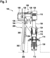
- Fig.3 shows the support leg 200 with an outer part 300 and an extendable inner part 302 slidably arranged in the outer part 300.
- the outer part 300 can have a plurality of locking openings 304 in its longitudinal direction, which serve to lock the two tubes 300, 302, for example by screwing.
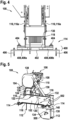
- Fig.4 shows an enlarged view of a foot 114 from the Figures 1 to 3
- the foot 114 is designed in the form of a plate assembly 400 consisting of the connecting plate 118 and a fastening plate 402.
- the connecting plate 118 can protrude beyond the support plates 116 on both sides, at least in the area of the foot 114, i.e. be significantly wider than a distance between the two support plates 116 in the transverse direction of the beam 102.
- the fastening plate 402 can in turn be significantly wider than the connecting plate 118 and thus protrude beyond the connecting plate 118 on both sides.
- the connecting plate 118 can be screwed to the fastening plate 402, for example, by means of two connecting screws 404.
- the fastening plate 402 can be screwed to the installation structure, for example, by means of two fastening screws 406.
- the Plate assembly 400 may additionally comprise an intermediate element 408 which is arranged between the fastening plate 402 and the connecting plate 118.
- the plate assembly 400 may include a left intermediate element 408a and a right intermediate element 408b, which may be arranged next to each other.
- the left intermediate element 408a may be placed opposite a left carrier plate 116a.
- the right intermediate element 408b may be placed opposite a right carrier plate 116b.
- Fig.5 shows a fastening device 100 similar to that of Fig.1 , with the difference that the deflection roller 130 is mounted hanging on the beam 102, as already shown in Fig.3 This results in a larger wrap angle on the traction sheave 110.
- the deflection roller 130 can be rotatably mounted in a deflection roller holder 500.
- the carrier plates 116 can each have a mounting section 502 to which the deflection roller holder 500 is attached, for example screwed, to both sides of the two carrier plates 116.
- the tower 124 is significantly shorter here than in the Figures 1 and 2 executed.
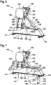
- Fig.6 shows a mounting device 100 with a long tower 124 (as in the Figures 1 and 2 ).
- the feet 114 are here in contrast to Fig.1 arranged at the outer ends of the beam 102.
- the deflection roller 130 is rotatably mounted between the two support plates 116.
- Fig.7 shows a mounting device 100 with a short tower 124 (as in Fig.5 ) and hanging mounted pulley bracket 500 (as shown in the Figures 3 and 5 ).
- the feet 114 are arranged at the outer ends of the beam 102.
- Fig.8 shows an elevator system 800 with the drive 106 and an installation structure 802 for installing the drive 106, for example in a machine room.
- the drive 106 is secured by means of the fastening device 100 as shown in Fig.1 shown, attached to the installation structure 802.
- the installation structure 802 comprises a base plate 804 with two openings 806 for passing through the support means 112.
- the fastening device 100 is attached to the base plate 804 with both feet 114.
- the support leg 200 is supported on the base plate 804 (only for better clarity, the support leg 200 is shown in the Figures 9 to 15 not shown).
- the drive 106 can, for example, be arranged directly above or below an elevator shaft or offset laterally therefrom in the machine room.
- the support means 112 can be deflected between the drive 106 and the elevator shaft by one or more deflection rollers 130.
- the installation structure 802 comprises an installation support 900 which is arranged on the base plate 804.
- the fastening device 100 rests with both feet 114 on the installation support 900.
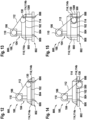
- Fig.10 shows the elevator system 800 with the fastening device 100 from Fig.5 .
- the fastening device 100 is similar to that in Fig.8 with both feet 114 attached to the base plate 804.
- the pulley holder 500 is recessed in the base plate 804.
- the fastening device 100 is attached to the installation support 900 with both feet 114.
- Fig. 12 shows the elevator system 800 with the fastening device 100 from Fig.6 .
- the fastening device 100 is fastened to the base plate 804 with both feet 114, wherein the two openings 806 of the base plate 804 are arranged between the feet 114.
- the installation structure 802 comprises a further installation support 1300.
- the two installation supports 900, 1300 are arranged parallel to one another at a certain distance on the base plate 804.
- the fastening device 100 rests with a left foot 114a on the installation support 900 and with a right foot 114b on the further installation support 1300.
- Fig. 14 shows the elevator system 800 with the fastening device 100 from Fig.7 .
- the fastening device 100 is similar to that in Fig.10 with both feet 114 attached to the base plate 804, whereby the pulley holder 500 is countersunk in the base plate 804.
- Fig. 15 the fastening device 100 is similar to Fig. 13 mounted on the two installation supports 900, 1300.
- the pulley bracket 500 hangs over the base plate 804.
Landscapes
- Engineering & Computer Science (AREA)
- Civil Engineering (AREA)
- Mechanical Engineering (AREA)
- Structural Engineering (AREA)
- Cage And Drive Apparatuses For Elevators (AREA)
Claims (13)
- Dispositif de fixation (100) permettant de fixer un entraînement (106) d'un système d'ascenseur (800), dans lequel le système d'ascenseur (800) comprend une structure d'installation (802) permettant d'installer l'entraînement (106), dans lequel le dispositif de fixation (100) comprend :une poutre (102) comportant deux pieds (114, 114a, 114b) permettant de fixer la poutre (102) à la structure d'installation (802) ;un moyen de maintien d'entraînement (104) permettant de recevoir l'entraînement (106), dans lequel le moyen de maintien d'entraînement (104) est fixé à la poutre (102) ; etune jambe de soutien (200) qui est fixée à une extrémité au moyen de soutien d'entraînement (104) et est conçue pour soutenir en outre le moyen de maintien d'entraînement (104) sur la structure d'installation (802),caractérisé en ce que la jambe de soutien (200) comprend deux éléments (300, 302) ou plus pouvant être déplacés l'un par rapport à l'autre, lesquels peuvent être déplacés de manière télescopique l'un dans l'autre et bloqués l'un contre l'autre, et la jambe de support (200) est ainsi réglable en longueur.
- Dispositif de fixation (100) selon la revendication 1,dans lequel la jambe de soutien (200) présente, à une autre extrémité, un pied de soutien (202) ;dans lequel le pied de soutien (202) repose à plat sur la structure d'installation (802) à l'état monté du dispositif de fixation (100).
- Dispositif de fixation (100) selon l'une des revendications précédentes,dans lequel la poutre (102) comprend deux plaques de support (116, 116a, 116b) parallèles reliées entre elles par l'intermédiaire d'au moins une plaque de liaison (118) ;dans lequel les pieds (114, 114a, 114b) sont fixés à l'au moins une plaque de liaison (118) ;dans lequel le moyen de maintien d'entraînement (104) est fixé aux plaques de support (116, 116a, 116b).
- Dispositif de fixation (100) selon la revendication 3,
dans lequel chacun des pieds (114, 114a, 114b) est formé par un assemblage de plaques (402) constitué de l'au moins une plaque de liaison (118) et d'une plaque de fixation (402) pour la fixation de la poutre (102) à la structure d'installation (802). - Dispositif de fixation (100) selon la revendication 4,
dans lequel la plaque de fixation (402) est plus large que l'au moins une plaque de liaison (118) et dépasse des deux côtés de l'au moins une plaque de liaison (118). - Dispositif de fixation (100) selon la revendication 4 ou 5,dans lequel l'assemblage de plaques (402) comprend en outre au moins un élément intermédiaire (408, 408a, 408b) ;dans lequel l'au moins un élément intermédiaire (408, 408a, 408b) est disposé entre la plaque de fixation (402) et l'au moins une plaque de liaison (118) ;dans lequel l'au moins une plaque de liaison (118) repose sur l'au moins un élément intermédiaire (408, 408a, 408b).
- Dispositif de fixation (100) selon la revendication 4 ou 5,dans lequel l'assemblage de plaques (402) comprend en outre un premier élément intermédiaire (408a) et un second élément intermédiaire (408b) ;dans lequel le premier élément intermédiaire (408a) et le second élément intermédiaire (408b) sont disposés côte à côte entre la plaque de fixation (402) et l'au moins une plaque de liaison (118) ;dans lequel l'au moins une plaque de liaison (118) repose sur le premier élément intermédiaire (408a) et le second élément intermédiaire (408b).
- Dispositif de fixation (100) selon l'une des revendications 4 à 7,
dans lequel les plaques de support (116, 116a, 116b) présentent respectivement au moins un réceptacle d'axe (132) permettant de recevoir un axe (134) d'une poulie de renvoi (130). - Dispositif de fixation (100) selon l'une des revendications 4 à 8,
dans lequel les plaques de support (116, 116a, 116b) présentent respectivement une section de montage (502) permettant le montage en suspension d'un moyen de maintien de poulie de renvoi (500). - Dispositif de fixation (100) selon l'une des revendications précédentes,
dans lequel les pieds (114, 114a, 114b) sont disposés aux extrémités de la poutre (102). - Dispositif de fixation (100) selon l'une des revendications précédentes,dans lequel le moyen de maintien d'entraînement (104) comprend une plaque d'entraînement (126) destinée à recevoir l'entraînement (106) et un élément formant tour (124) destiné à supporter la plaque d'entraînement (126) ;dans lequel la plaque d'entraînement (126) est fixée à une première extrémité de l'élément formant tour (124) et l'élément formant tour (124) est fixé à la poutre (102) avec une seconde extrémité.
- Système d'ascenseur (800), comprenant :un entraînement (106) ;une structure d'installation (802) permettant d'installer l'entraînement (106) ; etun dispositif de fixation (100) selon l'une des revendications précédentes, dans lequel l'entraînement (106) est fixé à la structure d'installation (802) au moyen du dispositif de fixation (100).
- Système d'ascenseur (800) selon la revendication 12,dans lequel la structure d'installation (802) comprend une plaque de base (804) et au moins un support d'installation (900 ; 1300) ;dans lequel la poutre (102) est fixée à l'au moins un support d'installation (900 ; 1300) par l'intermédiaire d'au moins l'un des pieds (114, 114a, 114b) et la jambe de soutien (200) soutient le moyen de maintien d'entraînement (104) sur la plaque de base (804).
Applications Claiming Priority (2)
| Application Number | Priority Date | Filing Date | Title |
|---|---|---|---|
| EP20166665 | 2020-03-30 | ||
| PCT/EP2021/058340 WO2021198282A1 (fr) | 2020-03-30 | 2021-03-30 | Dispositif de fixation conçu pour fixer un entraînement d'une installation d'ascenseur |
Publications (2)
| Publication Number | Publication Date |
|---|---|
| EP4126732A1 EP4126732A1 (fr) | 2023-02-08 |
| EP4126732B1 true EP4126732B1 (fr) | 2024-05-01 |
Family
ID=70058197
Family Applications (1)
| Application Number | Title | Priority Date | Filing Date |
|---|---|---|---|
| EP21716167.8A Active EP4126732B1 (fr) | 2020-03-30 | 2021-03-30 | Dispositif de fixation d'un entraînement d'une installation d'ascenseur |
Country Status (4)
| Country | Link |
|---|---|
| US (1) | US11970362B2 (fr) |
| EP (1) | EP4126732B1 (fr) |
| CN (1) | CN115362117B (fr) |
| WO (1) | WO2021198282A1 (fr) |
Families Citing this family (2)
| Publication number | Priority date | Publication date | Assignee | Title |
|---|---|---|---|---|
| DE102022122930A1 (de) * | 2022-09-09 | 2024-03-14 | Tk Elevator Innovation And Operations Gmbh | Aufzugsystem mit Installationshilfseinrichtung für eine oberhalb des Fahrwegs anordenbare Antriebseinheit sowie entsprechendes Installationsverfahren |
| CN118458556A (zh) * | 2023-02-07 | 2024-08-09 | 奥的斯电梯公司 | 电梯主机安装设备和电梯主机安装方法 |
Family Cites Families (16)
| Publication number | Priority date | Publication date | Assignee | Title |
|---|---|---|---|---|
| JPS5847784A (ja) * | 1981-09-17 | 1983-03-19 | 株式会社東芝 | 横引きエレベ−タ装置 |
| JP3747710B2 (ja) * | 1999-10-05 | 2006-02-22 | 松下電工株式会社 | エレベータ駆動装置の固定構造 |
| US6446762B1 (en) * | 1999-12-16 | 2002-09-10 | Otis Elevator Company | Elevator machine support frame mounted to hoistway wall |
| EP1302432B1 (fr) * | 2001-10-16 | 2011-12-14 | Inventio AG | Ensemble pour installer la machine d'ascenseur dans la cage |
| IL180964A (en) * | 2002-09-05 | 2010-11-30 | Inventio Ag | Drive engine for a lift installation and method of mounting a drive engine |
| US7377366B2 (en) * | 2002-11-25 | 2008-05-27 | Otis Elevator Company | Sheave assembly for an elevator system |
| CN2853730Y (zh) * | 2005-12-09 | 2007-01-03 | 黄文德 | 电梯施工升降台 |
| JP5092407B2 (ja) * | 2007-01-11 | 2012-12-05 | 三菱電機株式会社 | エレベータ装置 |
| FI125069B (fi) | 2009-10-28 | 2015-05-29 | Kone Corp | Hissin nostokoneiston kiinnitysjärjestely ja menetelmä hissin nostokoneiston asentamiseksi |
| EP2627849B1 (fr) * | 2010-10-13 | 2015-03-11 | Smart Level Company B.V. | Appareil de support et échelle pliable, escabeau ou échafaudage avec un tel appareil de support |
| CN104843566A (zh) * | 2015-04-17 | 2015-08-19 | 曾海平 | 外转子平面马达曳引机 |
| CN104876100A (zh) * | 2015-06-05 | 2015-09-02 | 苏州德朗控制技术有限公司 | 一种可调节对重的电梯 |
| CN107539866A (zh) * | 2016-06-29 | 2018-01-05 | 日立电梯(中国)有限公司 | 一种电梯驱动机的固定结构 |
| CN207844819U (zh) * | 2017-11-17 | 2018-09-11 | 王超 | 一种具有单电机双升降室驱动结构的升降电梯 |
| KR101993549B1 (ko) | 2018-01-04 | 2019-09-30 | 현대엘리베이터주식회사 | 경사지게 슬라이드 이동 가능한 권상기 베드를 포함하는 엘리베이터 시스템 |
| CN109019242A (zh) * | 2018-09-11 | 2018-12-18 | 管天奇 | 一种高层建筑用多重防护智能安全电梯 |
-
2021
- 2021-03-30 CN CN202180026338.2A patent/CN115362117B/zh active Active
- 2021-03-30 EP EP21716167.8A patent/EP4126732B1/fr active Active
- 2021-03-30 WO PCT/EP2021/058340 patent/WO2021198282A1/fr not_active Ceased
- 2021-03-30 US US17/907,283 patent/US11970362B2/en active Active
Also Published As
| Publication number | Publication date |
|---|---|
| CN115362117A (zh) | 2022-11-18 |
| US11970362B2 (en) | 2024-04-30 |
| US20230111475A1 (en) | 2023-04-13 |
| EP4126732A1 (fr) | 2023-02-08 |
| WO2021198282A1 (fr) | 2021-10-07 |
| CN115362117B (zh) | 2024-06-11 |
Similar Documents
| Publication | Publication Date | Title |
|---|---|---|
| AT508172B1 (de) | Handhabungsgerät und mast hierfür | |
| EP2194207B1 (fr) | Dispositif de support du panneau en verre d'un garde-corps | |
| DE3704598A1 (de) | Bewegliches geruest | |
| EP4126732B1 (fr) | Dispositif de fixation d'un entraînement d'une installation d'ascenseur | |
| DE60129115T2 (de) | Zugträger | |
| EP4267506B1 (fr) | Coulisseau, contrepoids équipée de coulisseau et installation d'ascenseur | |
| DE69600926T2 (de) | Gitterträger für tragende geländer von hängebühne | |
| EP4536577B1 (fr) | Système d'ascenseur | |
| DE2720337C2 (de) | Verstärkungsaufbau für eine Längsführung | |
| WO2022083965A1 (fr) | Ensemble pour siège de véhicule coulissant | |
| EP4536576B1 (fr) | Système d'ascenseur | |
| DE102005030757B4 (de) | Schiebetüranlage | |
| WO2018234136A1 (fr) | Ensemble de rails de guidage | |
| DE102021115852B4 (de) | Montageanordnung für den Innenausbau eines Schaltschrankgehäuses | |
| EP4263411A1 (fr) | Dispositif de fixation de rail pour des sections de rail de guidage d'un escalier roulant ou d'un trottoir roulant | |
| WO2018087381A1 (fr) | Cabine pour système d'ascenseur | |
| DE102007051630A1 (de) | Lastaufnahme für eine Hebebühne | |
| DE29919191U1 (de) | Laufschienenprofil und Laufschienenanlage zur Führung von Rollenapparaten | |
| DE202007013322U1 (de) | Laufschienensystem für Fahrwagen | |
| EP3865654B1 (fr) | Dispositif de support d'éléments de fenêtre ou de porte et procédé de montage d'un tel dispositif | |
| DE102009049951B4 (de) | Führungsschiene für einen Seilzug-Fensterheber eines Kraftfahrzeuges sowie Fensterheber | |
| DE10159242A1 (de) | Freistehendes Trennwandsystem | |
| DE102017127298A1 (de) | Baukasten zum Erstellen von Wechselbehälter-Tragrahmen, daraus erstellter Wechselbehälter-Tragrahmen sowie Verfahren zum Herstellen des Wechselbehälter-Tragrahmens | |
| DE3820884C2 (fr) | ||
| DE102024104370A1 (de) | Schlitten eines Fahrkorbrahmens zur Führung des Fahrkorbrahmens an zumindest einer Führungsschiene einer Aufzugsanlage |
Legal Events
| Date | Code | Title | Description |
|---|---|---|---|
| STAA | Information on the status of an ep patent application or granted ep patent |
Free format text: STATUS: UNKNOWN |
|
| STAA | Information on the status of an ep patent application or granted ep patent |
Free format text: STATUS: THE INTERNATIONAL PUBLICATION HAS BEEN MADE |
|
| PUAI | Public reference made under article 153(3) epc to a published international application that has entered the european phase |
Free format text: ORIGINAL CODE: 0009012 |
|
| STAA | Information on the status of an ep patent application or granted ep patent |
Free format text: STATUS: REQUEST FOR EXAMINATION WAS MADE |
|
| 17P | Request for examination filed |
Effective date: 20220822 |
|
| AK | Designated contracting states |
Kind code of ref document: A1 Designated state(s): AL AT BE BG CH CY CZ DE DK EE ES FI FR GB GR HR HU IE IS IT LI LT LU LV MC MK MT NL NO PL PT RO RS SE SI SK SM TR |
|
| DAV | Request for validation of the european patent (deleted) | ||
| DAX | Request for extension of the european patent (deleted) | ||
| GRAP | Despatch of communication of intention to grant a patent |
Free format text: ORIGINAL CODE: EPIDOSNIGR1 |
|
| STAA | Information on the status of an ep patent application or granted ep patent |
Free format text: STATUS: GRANT OF PATENT IS INTENDED |
|
| INTG | Intention to grant announced |
Effective date: 20231107 |
|
| GRAS | Grant fee paid |
Free format text: ORIGINAL CODE: EPIDOSNIGR3 |
|
| GRAA | (expected) grant |
Free format text: ORIGINAL CODE: 0009210 |
|
| STAA | Information on the status of an ep patent application or granted ep patent |
Free format text: STATUS: THE PATENT HAS BEEN GRANTED |
|
| AK | Designated contracting states |
Kind code of ref document: B1 Designated state(s): AL AT BE BG CH CY CZ DE DK EE ES FI FR GB GR HR HU IE IS IT LI LT LU LV MC MK MT NL NO PL PT RO RS SE SI SK SM TR |
|
| REG | Reference to a national code |
Ref country code: GB Ref legal event code: FG4D Free format text: NOT ENGLISH |
|
| REG | Reference to a national code |
Ref country code: CH Ref legal event code: EP |
|
| REG | Reference to a national code |
Ref country code: IE Ref legal event code: FG4D Free format text: LANGUAGE OF EP DOCUMENT: GERMAN |
|
| REG | Reference to a national code |
Ref country code: DE Ref legal event code: R096 Ref document number: 502021003579 Country of ref document: DE |
|
| REG | Reference to a national code |
Ref country code: LT Ref legal event code: MG9D |
|
| REG | Reference to a national code |
Ref country code: NL Ref legal event code: MP Effective date: 20240501 |
|
| PG25 | Lapsed in a contracting state [announced via postgrant information from national office to epo] |
Ref country code: IS Free format text: LAPSE BECAUSE OF FAILURE TO SUBMIT A TRANSLATION OF THE DESCRIPTION OR TO PAY THE FEE WITHIN THE PRESCRIBED TIME-LIMIT Effective date: 20240901 |
|
| PG25 | Lapsed in a contracting state [announced via postgrant information from national office to epo] |
Ref country code: BG Free format text: LAPSE BECAUSE OF FAILURE TO SUBMIT A TRANSLATION OF THE DESCRIPTION OR TO PAY THE FEE WITHIN THE PRESCRIBED TIME-LIMIT Effective date: 20240501 |
|
| PG25 | Lapsed in a contracting state [announced via postgrant information from national office to epo] |
Ref country code: FI Free format text: LAPSE BECAUSE OF FAILURE TO SUBMIT A TRANSLATION OF THE DESCRIPTION OR TO PAY THE FEE WITHIN THE PRESCRIBED TIME-LIMIT Effective date: 20240501 Ref country code: HR Free format text: LAPSE BECAUSE OF FAILURE TO SUBMIT A TRANSLATION OF THE DESCRIPTION OR TO PAY THE FEE WITHIN THE PRESCRIBED TIME-LIMIT Effective date: 20240501 |
|
| PG25 | Lapsed in a contracting state [announced via postgrant information from national office to epo] |
Ref country code: GR Free format text: LAPSE BECAUSE OF FAILURE TO SUBMIT A TRANSLATION OF THE DESCRIPTION OR TO PAY THE FEE WITHIN THE PRESCRIBED TIME-LIMIT Effective date: 20240802 |
|
| PG25 | Lapsed in a contracting state [announced via postgrant information from national office to epo] |
Ref country code: PT Free format text: LAPSE BECAUSE OF FAILURE TO SUBMIT A TRANSLATION OF THE DESCRIPTION OR TO PAY THE FEE WITHIN THE PRESCRIBED TIME-LIMIT Effective date: 20240902 |
|
| PG25 | Lapsed in a contracting state [announced via postgrant information from national office to epo] |
Ref country code: NL Free format text: LAPSE BECAUSE OF FAILURE TO SUBMIT A TRANSLATION OF THE DESCRIPTION OR TO PAY THE FEE WITHIN THE PRESCRIBED TIME-LIMIT Effective date: 20240501 |
|
| PG25 | Lapsed in a contracting state [announced via postgrant information from national office to epo] |
Ref country code: ES Free format text: LAPSE BECAUSE OF FAILURE TO SUBMIT A TRANSLATION OF THE DESCRIPTION OR TO PAY THE FEE WITHIN THE PRESCRIBED TIME-LIMIT Effective date: 20240501 |
|
| PG25 | Lapsed in a contracting state [announced via postgrant information from national office to epo] |
Ref country code: PL Free format text: LAPSE BECAUSE OF FAILURE TO SUBMIT A TRANSLATION OF THE DESCRIPTION OR TO PAY THE FEE WITHIN THE PRESCRIBED TIME-LIMIT Effective date: 20240501 |
|
| PG25 | Lapsed in a contracting state [announced via postgrant information from national office to epo] |
Ref country code: LV Free format text: LAPSE BECAUSE OF FAILURE TO SUBMIT A TRANSLATION OF THE DESCRIPTION OR TO PAY THE FEE WITHIN THE PRESCRIBED TIME-LIMIT Effective date: 20240501 |
|
| PG25 | Lapsed in a contracting state [announced via postgrant information from national office to epo] |
Ref country code: PT Free format text: LAPSE BECAUSE OF FAILURE TO SUBMIT A TRANSLATION OF THE DESCRIPTION OR TO PAY THE FEE WITHIN THE PRESCRIBED TIME-LIMIT Effective date: 20240902 Ref country code: PL Free format text: LAPSE BECAUSE OF FAILURE TO SUBMIT A TRANSLATION OF THE DESCRIPTION OR TO PAY THE FEE WITHIN THE PRESCRIBED TIME-LIMIT Effective date: 20240501 Ref country code: NO Free format text: LAPSE BECAUSE OF FAILURE TO SUBMIT A TRANSLATION OF THE DESCRIPTION OR TO PAY THE FEE WITHIN THE PRESCRIBED TIME-LIMIT Effective date: 20240801 Ref country code: NL Free format text: LAPSE BECAUSE OF FAILURE TO SUBMIT A TRANSLATION OF THE DESCRIPTION OR TO PAY THE FEE WITHIN THE PRESCRIBED TIME-LIMIT Effective date: 20240501 Ref country code: LV Free format text: LAPSE BECAUSE OF FAILURE TO SUBMIT A TRANSLATION OF THE DESCRIPTION OR TO PAY THE FEE WITHIN THE PRESCRIBED TIME-LIMIT Effective date: 20240501 Ref country code: IS Free format text: LAPSE BECAUSE OF FAILURE TO SUBMIT A TRANSLATION OF THE DESCRIPTION OR TO PAY THE FEE WITHIN THE PRESCRIBED TIME-LIMIT Effective date: 20240901 Ref country code: HR Free format text: LAPSE BECAUSE OF FAILURE TO SUBMIT A TRANSLATION OF THE DESCRIPTION OR TO PAY THE FEE WITHIN THE PRESCRIBED TIME-LIMIT Effective date: 20240501 Ref country code: GR Free format text: LAPSE BECAUSE OF FAILURE TO SUBMIT A TRANSLATION OF THE DESCRIPTION OR TO PAY THE FEE WITHIN THE PRESCRIBED TIME-LIMIT Effective date: 20240802 Ref country code: FI Free format text: LAPSE BECAUSE OF FAILURE TO SUBMIT A TRANSLATION OF THE DESCRIPTION OR TO PAY THE FEE WITHIN THE PRESCRIBED TIME-LIMIT Effective date: 20240501 Ref country code: ES Free format text: LAPSE BECAUSE OF FAILURE TO SUBMIT A TRANSLATION OF THE DESCRIPTION OR TO PAY THE FEE WITHIN THE PRESCRIBED TIME-LIMIT Effective date: 20240501 Ref country code: BG Free format text: LAPSE BECAUSE OF FAILURE TO SUBMIT A TRANSLATION OF THE DESCRIPTION OR TO PAY THE FEE WITHIN THE PRESCRIBED TIME-LIMIT Effective date: 20240501 Ref country code: RS Free format text: LAPSE BECAUSE OF FAILURE TO SUBMIT A TRANSLATION OF THE DESCRIPTION OR TO PAY THE FEE WITHIN THE PRESCRIBED TIME-LIMIT Effective date: 20240801 |
|
| PG25 | Lapsed in a contracting state [announced via postgrant information from national office to epo] |
Ref country code: DK Free format text: LAPSE BECAUSE OF FAILURE TO SUBMIT A TRANSLATION OF THE DESCRIPTION OR TO PAY THE FEE WITHIN THE PRESCRIBED TIME-LIMIT Effective date: 20240501 |
|
| PG25 | Lapsed in a contracting state [announced via postgrant information from national office to epo] |
Ref country code: EE Free format text: LAPSE BECAUSE OF FAILURE TO SUBMIT A TRANSLATION OF THE DESCRIPTION OR TO PAY THE FEE WITHIN THE PRESCRIBED TIME-LIMIT Effective date: 20240501 |
|
| PG25 | Lapsed in a contracting state [announced via postgrant information from national office to epo] |
Ref country code: CZ Free format text: LAPSE BECAUSE OF FAILURE TO SUBMIT A TRANSLATION OF THE DESCRIPTION OR TO PAY THE FEE WITHIN THE PRESCRIBED TIME-LIMIT Effective date: 20240501 |
|
| PG25 | Lapsed in a contracting state [announced via postgrant information from national office to epo] |
Ref country code: SK Free format text: LAPSE BECAUSE OF FAILURE TO SUBMIT A TRANSLATION OF THE DESCRIPTION OR TO PAY THE FEE WITHIN THE PRESCRIBED TIME-LIMIT Effective date: 20240501 Ref country code: RO Free format text: LAPSE BECAUSE OF FAILURE TO SUBMIT A TRANSLATION OF THE DESCRIPTION OR TO PAY THE FEE WITHIN THE PRESCRIBED TIME-LIMIT Effective date: 20240501 |
|
| PG25 | Lapsed in a contracting state [announced via postgrant information from national office to epo] |
Ref country code: SM Free format text: LAPSE BECAUSE OF FAILURE TO SUBMIT A TRANSLATION OF THE DESCRIPTION OR TO PAY THE FEE WITHIN THE PRESCRIBED TIME-LIMIT Effective date: 20240501 |
|
| PG25 | Lapsed in a contracting state [announced via postgrant information from national office to epo] |
Ref country code: SM Free format text: LAPSE BECAUSE OF FAILURE TO SUBMIT A TRANSLATION OF THE DESCRIPTION OR TO PAY THE FEE WITHIN THE PRESCRIBED TIME-LIMIT Effective date: 20240501 Ref country code: SK Free format text: LAPSE BECAUSE OF FAILURE TO SUBMIT A TRANSLATION OF THE DESCRIPTION OR TO PAY THE FEE WITHIN THE PRESCRIBED TIME-LIMIT Effective date: 20240501 Ref country code: RO Free format text: LAPSE BECAUSE OF FAILURE TO SUBMIT A TRANSLATION OF THE DESCRIPTION OR TO PAY THE FEE WITHIN THE PRESCRIBED TIME-LIMIT Effective date: 20240501 Ref country code: EE Free format text: LAPSE BECAUSE OF FAILURE TO SUBMIT A TRANSLATION OF THE DESCRIPTION OR TO PAY THE FEE WITHIN THE PRESCRIBED TIME-LIMIT Effective date: 20240501 Ref country code: DK Free format text: LAPSE BECAUSE OF FAILURE TO SUBMIT A TRANSLATION OF THE DESCRIPTION OR TO PAY THE FEE WITHIN THE PRESCRIBED TIME-LIMIT Effective date: 20240501 Ref country code: CZ Free format text: LAPSE BECAUSE OF FAILURE TO SUBMIT A TRANSLATION OF THE DESCRIPTION OR TO PAY THE FEE WITHIN THE PRESCRIBED TIME-LIMIT Effective date: 20240501 |
|
| REG | Reference to a national code |
Ref country code: DE Ref legal event code: R097 Ref document number: 502021003579 Country of ref document: DE |
|
| PG25 | Lapsed in a contracting state [announced via postgrant information from national office to epo] |
Ref country code: IT Free format text: LAPSE BECAUSE OF FAILURE TO SUBMIT A TRANSLATION OF THE DESCRIPTION OR TO PAY THE FEE WITHIN THE PRESCRIBED TIME-LIMIT Effective date: 20240501 |
|
| PLBE | No opposition filed within time limit |
Free format text: ORIGINAL CODE: 0009261 |
|
| STAA | Information on the status of an ep patent application or granted ep patent |
Free format text: STATUS: NO OPPOSITION FILED WITHIN TIME LIMIT |
|
| 26N | No opposition filed |
Effective date: 20250204 |
|
| PGFP | Annual fee paid to national office [announced via postgrant information from national office to epo] |
Ref country code: DE Payment date: 20250327 Year of fee payment: 5 |
|
| PG25 | Lapsed in a contracting state [announced via postgrant information from national office to epo] |
Ref country code: SI Free format text: LAPSE BECAUSE OF FAILURE TO SUBMIT A TRANSLATION OF THE DESCRIPTION OR TO PAY THE FEE WITHIN THE PRESCRIBED TIME-LIMIT Effective date: 20240501 |
|
| PGFP | Annual fee paid to national office [announced via postgrant information from national office to epo] |
Ref country code: AT Payment date: 20250417 Year of fee payment: 5 |
|
| PGFP | Annual fee paid to national office [announced via postgrant information from national office to epo] |
Ref country code: CH Payment date: 20250401 Year of fee payment: 5 |
|
| PG25 | Lapsed in a contracting state [announced via postgrant information from national office to epo] |
Ref country code: SE Free format text: LAPSE BECAUSE OF FAILURE TO SUBMIT A TRANSLATION OF THE DESCRIPTION OR TO PAY THE FEE WITHIN THE PRESCRIBED TIME-LIMIT Effective date: 20240501 |
|
| PG25 | Lapsed in a contracting state [announced via postgrant information from national office to epo] |
Ref country code: MC Free format text: LAPSE BECAUSE OF FAILURE TO SUBMIT A TRANSLATION OF THE DESCRIPTION OR TO PAY THE FEE WITHIN THE PRESCRIBED TIME-LIMIT Effective date: 20240501 |
|
| PG25 | Lapsed in a contracting state [announced via postgrant information from national office to epo] |
Ref country code: LU Free format text: LAPSE BECAUSE OF NON-PAYMENT OF DUE FEES Effective date: 20250330 |
|
| REG | Reference to a national code |
Ref country code: BE Ref legal event code: MM Effective date: 20250331 |
|
| PG25 | Lapsed in a contracting state [announced via postgrant information from national office to epo] |
Ref country code: BE Free format text: LAPSE BECAUSE OF NON-PAYMENT OF DUE FEES Effective date: 20250331 |
|
| PG25 | Lapsed in a contracting state [announced via postgrant information from national office to epo] |
Ref country code: IE Free format text: LAPSE BECAUSE OF NON-PAYMENT OF DUE FEES Effective date: 20250330 |
|
| REG | Reference to a national code |
Ref country code: CH Ref legal event code: U11 Free format text: ST27 STATUS EVENT CODE: U-0-0-U10-U11 (AS PROVIDED BY THE NATIONAL OFFICE) Effective date: 20260401 |
|
| PGFP | Annual fee paid to national office [announced via postgrant information from national office to epo] |
Ref country code: GB Payment date: 20260319 Year of fee payment: 6 |
|
| PGFP | Annual fee paid to national office [announced via postgrant information from national office to epo] |
Ref country code: FR Payment date: 20260323 Year of fee payment: 6 |