EP2194268A1 - Installation d'énergie éolienne à génératrice annulaire - Google Patents
Installation d'énergie éolienne à génératrice annulaire Download PDFInfo
- Publication number
- EP2194268A1 EP2194268A1 EP10156260A EP10156260A EP2194268A1 EP 2194268 A1 EP2194268 A1 EP 2194268A1 EP 10156260 A EP10156260 A EP 10156260A EP 10156260 A EP10156260 A EP 10156260A EP 2194268 A1 EP2194268 A1 EP 2194268A1
- Authority
- EP
- European Patent Office
- Prior art keywords
- stator
- winding
- drums
- grooves
- support
- Prior art date
- Legal status (The legal status is an assumption and is not a legal conclusion. Google has not performed a legal analysis and makes no representation as to the accuracy of the status listed.)
- Granted
Links
- 238000009434 installation Methods 0.000 title 1
- 230000001360 synchronised effect Effects 0.000 claims abstract description 9
- 239000004020 conductor Substances 0.000 claims description 63
- 238000004804 winding Methods 0.000 claims description 55
- 230000002349 favourable effect Effects 0.000 abstract description 4
- 238000004519 manufacturing process Methods 0.000 description 4
- 230000000694 effects Effects 0.000 description 3
- 238000006073 displacement reaction Methods 0.000 description 2
- 229910000679 solder Inorganic materials 0.000 description 2
- 230000007704 transition Effects 0.000 description 2
- 230000001174 ascending effect Effects 0.000 description 1
- 230000015572 biosynthetic process Effects 0.000 description 1
- 239000011248 coating agent Substances 0.000 description 1
- 238000000576 coating method Methods 0.000 description 1
- 230000001447 compensatory effect Effects 0.000 description 1
- 150000001875 compounds Chemical class 0.000 description 1
- 238000010276 construction Methods 0.000 description 1
- 230000007547 defect Effects 0.000 description 1
- 238000000034 method Methods 0.000 description 1
- 238000000819 phase cycle Methods 0.000 description 1
- 238000002360 preparation method Methods 0.000 description 1
Images

Classifications
-
- H—ELECTRICITY
- H02—GENERATION; CONVERSION OR DISTRIBUTION OF ELECTRIC POWER
- H02K—DYNAMO-ELECTRIC MACHINES
- H02K3/00—Details of windings
- H02K3/04—Windings characterised by the conductor shape, form or construction, e.g. with bar conductors
- H02K3/12—Windings characterised by the conductor shape, form or construction, e.g. with bar conductors arranged in slots
- H02K3/14—Windings characterised by the conductor shape, form or construction, e.g. with bar conductors arranged in slots with transposed conductors, e.g. twisted conductors
-
- F—MECHANICAL ENGINEERING; LIGHTING; HEATING; WEAPONS; BLASTING
- F03—MACHINES OR ENGINES FOR LIQUIDS; WIND, SPRING, OR WEIGHT MOTORS; PRODUCING MECHANICAL POWER OR A REACTIVE PROPULSIVE THRUST, NOT OTHERWISE PROVIDED FOR
- F03D—WIND MOTORS
- F03D9/00—Adaptations of wind motors for special use; Combinations of wind motors with apparatus driven thereby; Wind motors specially adapted for installation in particular locations
-
- F—MECHANICAL ENGINEERING; LIGHTING; HEATING; WEAPONS; BLASTING
- F03—MACHINES OR ENGINES FOR LIQUIDS; WIND, SPRING, OR WEIGHT MOTORS; PRODUCING MECHANICAL POWER OR A REACTIVE PROPULSIVE THRUST, NOT OTHERWISE PROVIDED FOR
- F03D—WIND MOTORS
- F03D9/00—Adaptations of wind motors for special use; Combinations of wind motors with apparatus driven thereby; Wind motors specially adapted for installation in particular locations
- F03D9/20—Wind motors characterised by the driven apparatus
- F03D9/25—Wind motors characterised by the driven apparatus the apparatus being an electrical generator
-
- H—ELECTRICITY
- H02—GENERATION; CONVERSION OR DISTRIBUTION OF ELECTRIC POWER
- H02K—DYNAMO-ELECTRIC MACHINES
- H02K15/00—Processes or apparatus specially adapted for manufacturing, assembling, maintaining or repairing of dynamo-electric machines
- H02K15/08—Forming windings by laying conductors into or around core parts
- H02K15/085—Forming windings by laying conductors into or around core parts by laying conductors into slotted stators
-
- H—ELECTRICITY
- H02—GENERATION; CONVERSION OR DISTRIBUTION OF ELECTRIC POWER
- H02K—DYNAMO-ELECTRIC MACHINES
- H02K3/00—Details of windings
- H02K3/04—Windings characterised by the conductor shape, form or construction, e.g. with bar conductors
- H02K3/12—Windings characterised by the conductor shape, form or construction, e.g. with bar conductors arranged in slots
-
- H—ELECTRICITY
- H02—GENERATION; CONVERSION OR DISTRIBUTION OF ELECTRIC POWER
- H02K—DYNAMO-ELECTRIC MACHINES
- H02K3/00—Details of windings
- H02K3/04—Windings characterised by the conductor shape, form or construction, e.g. with bar conductors
- H02K3/28—Layout of windings or of connections between windings
-
- F—MECHANICAL ENGINEERING; LIGHTING; HEATING; WEAPONS; BLASTING
- F05—INDEXING SCHEMES RELATING TO ENGINES OR PUMPS IN VARIOUS SUBCLASSES OF CLASSES F01-F04
- F05B—INDEXING SCHEME RELATING TO WIND, SPRING, WEIGHT, INERTIA OR LIKE MOTORS, TO MACHINES OR ENGINES FOR LIQUIDS COVERED BY SUBCLASSES F03B, F03D AND F03G
- F05B2220/00—Application
- F05B2220/70—Application in combination with
- F05B2220/706—Application in combination with an electrical generator
- F05B2220/7064—Application in combination with an electrical generator of the alternating current (A.C.) type
- F05B2220/70642—Application in combination with an electrical generator of the alternating current (A.C.) type of the synchronous type
-
- H—ELECTRICITY
- H02—GENERATION; CONVERSION OR DISTRIBUTION OF ELECTRIC POWER
- H02K—DYNAMO-ELECTRIC MACHINES
- H02K2203/00—Specific aspects not provided for in the other groups of this subclass relating to the windings
- H02K2203/15—Machines characterised by cable windings, e.g. high-voltage cables, ribbon cables
-
- H—ELECTRICITY
- H02—GENERATION; CONVERSION OR DISTRIBUTION OF ELECTRIC POWER
- H02K—DYNAMO-ELECTRIC MACHINES
- H02K7/00—Arrangements for handling mechanical energy structurally associated with dynamo-electric machines, e.g. structural association with mechanical driving motors or auxiliary dynamo-electric machines
- H02K7/18—Structural association of electric generators with mechanical driving motors, e.g. with turbines
- H02K7/1807—Rotary generators
- H02K7/1823—Rotary generators structurally associated with turbines or similar engines
- H02K7/183—Rotary generators structurally associated with turbines or similar engines wherein the turbine is a wind turbine
- H02K7/1838—Generators mounted in a nacelle or similar structure of a horizontal axis wind turbine
-
- Y—GENERAL TAGGING OF NEW TECHNOLOGICAL DEVELOPMENTS; GENERAL TAGGING OF CROSS-SECTIONAL TECHNOLOGIES SPANNING OVER SEVERAL SECTIONS OF THE IPC; TECHNICAL SUBJECTS COVERED BY FORMER USPC CROSS-REFERENCE ART COLLECTIONS [XRACs] AND DIGESTS
- Y02—TECHNOLOGIES OR APPLICATIONS FOR MITIGATION OR ADAPTATION AGAINST CLIMATE CHANGE
- Y02E—REDUCTION OF GREENHOUSE GAS [GHG] EMISSIONS, RELATED TO ENERGY GENERATION, TRANSMISSION OR DISTRIBUTION
- Y02E10/00—Energy generation through renewable energy sources
- Y02E10/70—Wind energy
- Y02E10/72—Wind turbines with rotation axis in wind direction
-
- Y—GENERAL TAGGING OF NEW TECHNOLOGICAL DEVELOPMENTS; GENERAL TAGGING OF CROSS-SECTIONAL TECHNOLOGIES SPANNING OVER SEVERAL SECTIONS OF THE IPC; TECHNICAL SUBJECTS COVERED BY FORMER USPC CROSS-REFERENCE ART COLLECTIONS [XRACs] AND DIGESTS
- Y10—TECHNICAL SUBJECTS COVERED BY FORMER USPC
- Y10T—TECHNICAL SUBJECTS COVERED BY FORMER US CLASSIFICATION
- Y10T29/00—Metal working
- Y10T29/49—Method of mechanical manufacture
- Y10T29/49002—Electrical device making
- Y10T29/49009—Dynamoelectric machine
-
- Y—GENERAL TAGGING OF NEW TECHNOLOGICAL DEVELOPMENTS; GENERAL TAGGING OF CROSS-SECTIONAL TECHNOLOGIES SPANNING OVER SEVERAL SECTIONS OF THE IPC; TECHNICAL SUBJECTS COVERED BY FORMER USPC CROSS-REFERENCE ART COLLECTIONS [XRACs] AND DIGESTS
- Y10—TECHNICAL SUBJECTS COVERED BY FORMER USPC
- Y10T—TECHNICAL SUBJECTS COVERED BY FORMER US CLASSIFICATION
- Y10T29/00—Metal working
- Y10T29/51—Plural diverse manufacturing apparatus including means for metal shaping or assembling
- Y10T29/5187—Wire working
-
- Y—GENERAL TAGGING OF NEW TECHNOLOGICAL DEVELOPMENTS; GENERAL TAGGING OF CROSS-SECTIONAL TECHNOLOGIES SPANNING OVER SEVERAL SECTIONS OF THE IPC; TECHNICAL SUBJECTS COVERED BY FORMER USPC CROSS-REFERENCE ART COLLECTIONS [XRACs] AND DIGESTS
- Y10—TECHNICAL SUBJECTS COVERED BY FORMER USPC
- Y10T—TECHNICAL SUBJECTS COVERED BY FORMER US CLASSIFICATION
- Y10T29/00—Metal working
- Y10T29/53—Means to assemble or disassemble
- Y10T29/5313—Means to assemble electrical device
- Y10T29/53143—Motor or generator
-
- Y—GENERAL TAGGING OF NEW TECHNOLOGICAL DEVELOPMENTS; GENERAL TAGGING OF CROSS-SECTIONAL TECHNOLOGIES SPANNING OVER SEVERAL SECTIONS OF THE IPC; TECHNICAL SUBJECTS COVERED BY FORMER USPC CROSS-REFERENCE ART COLLECTIONS [XRACs] AND DIGESTS
- Y10—TECHNICAL SUBJECTS COVERED BY FORMER USPC
- Y10T—TECHNICAL SUBJECTS COVERED BY FORMER US CLASSIFICATION
- Y10T29/00—Metal working
- Y10T29/53—Means to assemble or disassemble
- Y10T29/5313—Means to assemble electrical device
- Y10T29/53143—Motor or generator
- Y10T29/53148—Means to assemble commutator
Definitions
- the present invention relates to a wind turbine with a generator having a stator, wherein the grooves are formed at the inner or outer periphery spaced from each other for receiving a stator winding.
- Such wind turbines are known and are e.g. manufactured and sold by ENERCON.
- stator windings in generators involves the use of so-called form coils. These form coils are in their form already adapted to the grooves and groove distances of the stator individual windings of the stator winding, which are first inserted individually into the grooves and then connected to each other.
- the generator of the wind turbine which is subjected to mechanical and electrical stresses. From this combination problems arise when z. B. as a result of high electrical currents generated, the temperature in the region of the generator is also high and as a result of mechanical stress connections between individual components are subjected to vibrations. If, due to the thermal expansion, there is still a slight play or loosening, the mechanical loads here can lead to a defect or even damage.
- this phase for the generation of energy fails. Furthermore, there is an additional asymmetric load in the generator, since this phase acts as a result of the interruption as in idle mode. Mechanical damage caused by loose and freely moving components such as connecting sleeves are not even taken into account.
- the object of the present invention is therefore to specify a stator with a winding in which these problems explained above are at least reduced.
- all phases are wound continuously on the stator in each case.
- the windings are produced from at least two conductor bundles, wherein a plurality of mutually insulated conductors is present in each conductor bundle.
- These conductor bundles are inserted into grooves of the stator in a predetermined sequence and the sequence is changed at likewise predetermined intervals, so that alternately each of the conductor bundles is affected as evenly as possible by these effects. Due to this uniform influencing of all conductor bundles of a phase, compensatory measures can be dispensed with.
- the stator In order to facilitate the handling of the stator during the manufacture of the winding and to provide a work-physiologically favorable situation, the stator is held in a bearing device in which the grooves are at a favorable working height for the production of the winding and a rotation of the stator in the circumferential direction a desired level is allowed. This can preferably be done using a motor drive.
- At least one carrying device for carrying at least one coil with winding wire is furthermore provided.
- This support allows the handling of the winding wire, z. B. in the form of conductor bundles whose length is inventively dimensioned so that the phase can be continuously wound on the stator.
- the required length of the conductor bundles leads to a considerable weight, which is manually no longer manageable.
- two drums each with winding wire are handled in pairs so as to be able to handle both conductor bundles simultaneously, and a support carries three pairs of drums with winding wire, so that using such a support device, a three-phase system with two conductor bundles per phase can be wound on the stator.
- the drums are arranged with the winding wire pivotable about a central axis of rotation of the support device.
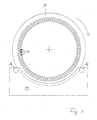
- Reference numeral 10 denotes the stator having grooves 12 extending in the axial direction on the inner circumference. This is the most common type of generator.
- the (not shown) runner is located within the stator 10. This design is referred to as an inner rotor.
- the grooves 12 may be provided on the outer circumference of the stator.
- the grooves 12 are shown enlarged in the figure.
- the stator 10 is held in a holding device 14, which stands on the ground and thus holds the stator 10 and in particular the grooves 12 at a height which forms a working physiologically favorable working position.
- stator 10 of a ring generator has a diameter of several meters and correspondingly high weight
- stator 10 is rotatably mounted on pivot bearings 16 and can be rotated, for example, in the direction of the arrow by a desired amount to the machined grooves 12 in a to bring desired position.
- this rotation of the stator 10 may be accomplished using a drive motor (not shown).
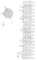
- a conductor bundle 20 is shown, which consists of a plurality of individual conductors 22, which as a bundle in the grooves (reference numeral 12 in FIG Fig. 1 ) be inserted.
- the individual conductors 22 are insulated from each other by a coating.
- conductor bundles 20 from individual conductors 22 has the advantage that these conductor bundles are not fixed in their cross-sectional shape, but are variable, so that they are guided on the one hand by a relatively narrow groove opening, but on the other hand then can fill the wider groove cross-section as much as possible by appropriate deformation to obtain a good filling factor of the groove (reference 12 in FIG Fig. 1 ) to reach.
- Fig. 3a shows a developed section of the inner circumference of the stator 10.
- the grooves 12 are arranged horizontally next to each other here.
- the conductor bundles are inserted, which are simplified here shown as circular conductor bundles 20.
- two of these conductor bundles 20 are combined into one turn of a phase.
- webs 24 each connecting two of the conductor bundles 20.
- two turns of a phase are inserted into each groove as shown in this figure.
- the individual conductor bundles are numbered from bottom to top with numbers 1 to 4. To distinguish the individual phases of the six-phase system shown here, these are identified below the groove with the names P1 - P6.
- the phases P1 - P6 are shown side by side in ascending order and the sequence of the conductor bundles is indicated by the reference numerals 4, 3, 2, 1.
- this phase sequence repeats beginning with P1.
- the order of the conductor bundles 20 is now changed.
- the first turn arranged in the groove 12 below still consists of the conductor bundles 1 and 2, these are interchanged in their order.
- the second winding still consists of the conductor bundles 20 designated 3 and 4, but these are also reversed in their order.
- the arranged next phase P6 again has the already known sequence of the conductor bundles.
- phase P1 - P6 are shown in the right part of this figure again.
- the conductor bundles 20 of the phase P5 denoted by 1 and 2 or 3 and 4 are likewise shown reversed here.
- the conductor bundles 20 denoted by 1 and 2 also form the first turn and the bundles of conductors 20 denoted by 3 and 4 form the second turn of this phase, but in turn the position of the conductor bundles is interchanged within the turn.
- both conductor bundles 20 are alternately subjected to this action in a turn, so that with suitable selection of the position of exchange and frequency both conductor bundles 20 are subjected to a phase of this effect approximately uniformly, so that significant equalizing currents, the result from an uneven loading, not flow and thus the maximum possible power can be delivered by the generator.
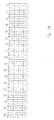
- Fig. 3b shows the representation of the stator with inserted therein stator windings or stator, which can be seen that the Statornuten are largely filled with the windings and wherein the direction of current flow in the conductors (arrowhead, arrow cross) can be seen.
- the arrangement is opposite to the phases Fig. 3a changed to better illustrate the change in the winding sense.
- the representation according to Fig. 3b But also makes it clear that more than 80%, preferably more than 95% of the total space of the stator is filled with windings and thus the proportion of air in the stator is extremely low.
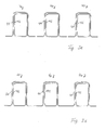
- Fig. 3c shows a part of a conventionally produced winding, but without the representation of the stator and the grooves in which the winding is inserted.
- the winding is formed from form coils 40 having two turns 41, 42. These windings 41, 42 are shown offset from each other for better visibility. Of course, in the groove (not shown in this figure), these are arranged exactly one above the other.
- the distance results from the fact that alternately form coils of the other phases of the stator are arranged between form coils of this phase, but are not shown in the figure.
- the connection of the forming coils 40 of a phase with each other can be done by solder joints or screw-clamp connections or similar techniques.
- Fig. 3d shows the inventive embodiment of a continuously wound phase. Again, according to the illustration in Fig. 3b again a part of the winding of a phase shown. In this case, the individual turns 41, 42 are also shown offset from each other to illustrate the nature of the execution.
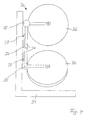
- Fig. 4 shows a support device 30 for the conductor bundles used as winding wires in the side view.
- An L-shaped base frame 31 ensures a secure footing of the entire support device 30.
- a support plate 32 is connected via a pivot bearing 33 with the base frame 31.
- On the support plate 32 supporting arms 34 are fixed, which extend from the center of the support plate 32 from a predetermined portion to the periphery of the support plate 32 toward and extend a predetermined length substantially horizontally from the support plate 32 away.
- drums 36 are rotatably mounted with the conductor bundles used as a winding wire.
- pivot bearing (not shown) is provided between the parallel to the support plate 32 extending vertical portion of the support arm 34 and its horizontally extending portion. This pivot bearing cooperates with a drive 35 and allows rotation of the horizontal portion of the support arm 34 about its longitudinal axis together with the drums 36 disposed thereon. This can be counteracted a twist that arises during winding of the stator winding between the conductor bundles of this winding.
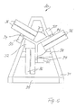
- Fig. 5 shows a front view of this support device 30. Here is a from the base to the tip tapering base frame 31 is shown. To increase the stability of two trusses 38 and 39 are provided.
- the support plate 32 is rotatably mounted on the support plate 32 are three each offset by an equal angle (120 °) support arms 34 are arranged, are attached to the substantially horizontally extending arms each two drums 36 for the conductor bundles. Due to the rotatable mounting of the support plate 32 and thus firmly connected via the support arms 34 drums 36 can be rotated by a second motor 37.
- each conductor bundle 20 is inserted into a groove 12, bent at the end of the groove 12 in the winding head and led to a new, parallel groove 12 in the winding head. Then the conductor bundle 20 is again bent so that it can be inserted into this groove 12. At the exit of this groove 12, the conductor bundle 20 in the winding head is in turn bent so that it can be guided to the next groove 12. This results in course in the direction of the drum 36 extending conductor bundle 20, a corresponding rotation.
- the drums 36 are arranged in pairs on the horizontal portions of the support arms 34. Since these horizontal sections are rotatable about their longitudinal axis by the drives 35, the drums 36 are rotated. In this way, a twisting of the conductor bundles can be counteracted by turning the corresponding support arm 34.
- a second drive 37 is disposed between the base frame 31 and the support plate 32 and allows rotation of the support plate 32 with all support arms 34 and drums 36 disposed thereon to also perform the rotation of the stator 10 in the stator holder 14 and thus to twist the To avoid conductor bundles.
- Fig. 6 shows simplified and without a conductor bundle between the support devices 30 and the stator 10, the arrangement of two support devices 30 and a stator to be wound 10.
- the stator 10 is mounted in a holding device 14 and in the circumferential direction (arrow) rotatable. Since each of the support devices 30 also has rotatably mounted drums 36, they can perform the rotation of the stator by a corresponding rotation with. By providing two carrying devices 30 with three pairs of drums can thus simultaneously six phases are wound on a stator.
- the present invention is applicable not only to ring generators for wind turbines, but in principle to any synchronous machine, which must be made clear that this is not the smallest machines, but machines that have a considerable spatial extent and which regularly have connection values of possibly several 100 kW and more.
- a rated output of more than 500 kW is typical for a ring generator of a wind energy plant; even generators with a nominal power of more than 4 MW are already being tested and will be used in the future.
- Only the stator of the described synchronous machine weighs several tons, with ring generators with more than 4 MW, possibly even more than 50 tons.
- Wind turbine with a (ring) generator having a stator in which grooves are formed at the inner or outer periphery spaced from each other for receiving a stator winding, wherein the winding is wound continuously without interruption.
- Wind energy plant according to Example 1 characterized by a stator (10) with at least two continuously wound phase windings, preferably 6-phase windings.
- Wind energy plant according to one of the examples 1, 2 or 3, characterized in that adjacent groove windings of different phases are arranged.
- Wind energy plant characterized in that the winding of a phase of at least one conductor bundle, preferably consists of at least two conductor bundles, wherein a conductor bundle consists of a plurality of mutually insulated conductors.
- Wind energy plant according to Example 5 characterized in that at least two conductor bundles are arranged one above the other in a groove.
- Wind energy plant according to Example 6 characterized in that in grooves in which a plurality of conductor bundles are arranged, the layers of the upper and lower conductor bundles are reversed in a predetermined order.
- Wind energy plant according to one of the examples 1, 2, 3, 4, 5, 6 or 7, characterized in that in each groove two turns are inserted, which preferably correspond to the same phase.
Landscapes
- Engineering & Computer Science (AREA)
- Power Engineering (AREA)
- Mechanical Engineering (AREA)
- General Engineering & Computer Science (AREA)
- Sustainable Development (AREA)
- Sustainable Energy (AREA)
- Chemical & Material Sciences (AREA)
- Combustion & Propulsion (AREA)
- Life Sciences & Earth Sciences (AREA)
- Manufacturing & Machinery (AREA)
- Windings For Motors And Generators (AREA)
- Iron Core Of Rotating Electric Machines (AREA)
- Connection Of Motors, Electrical Generators, Mechanical Devices, And The Like (AREA)
- Manufacture Of Motors, Generators (AREA)
- Motor Or Generator Frames (AREA)
- Insulation, Fastening Of Motor, Generator Windings (AREA)
- Wind Motors (AREA)
Applications Claiming Priority (5)
| Application Number | Priority Date | Filing Date | Title |
|---|---|---|---|
| DE10137270A DE10137270A1 (de) | 2001-07-31 | 2001-07-31 | Windenergieanlage mit Ringgenerator |
| DE10145018A DE10145018A1 (de) | 2001-07-31 | 2001-09-13 | Windenergieanlage mit Ringgenerator |
| EP02754757A EP1419315B1 (fr) | 2001-07-31 | 2002-06-26 | Installation d'energie eolienne a generatrice annulaire |
| PCT/EP2002/007045 WO2003012292A1 (fr) | 2001-07-31 | 2002-06-26 | Installation d'energie eolienne a generatrice annulaire |
| EP05102273A EP1574708B1 (fr) | 2001-07-31 | 2002-06-26 | Installation d'énergie éolienne à génératrice annulaire |
Related Parent Applications (4)
| Application Number | Title | Priority Date | Filing Date |
|---|---|---|---|
| EP02754757.9 Division | 2002-06-26 | ||
| EP02754757A Division EP1419315B1 (fr) | 2001-07-31 | 2002-06-26 | Installation d'energie eolienne a generatrice annulaire |
| EP05102273A Division EP1574708B1 (fr) | 2001-07-31 | 2002-06-26 | Installation d'énergie éolienne à génératrice annulaire |
| EP05102273.9 Division | 2005-03-22 |
Publications (2)
| Publication Number | Publication Date |
|---|---|
| EP2194268A1 true EP2194268A1 (fr) | 2010-06-09 |
| EP2194268B1 EP2194268B1 (fr) | 2019-04-24 |
Family
ID=7693713
Family Applications (3)
| Application Number | Title | Priority Date | Filing Date |
|---|---|---|---|
| EP02754757A Expired - Lifetime EP1419315B1 (fr) | 2001-07-31 | 2002-06-26 | Installation d'energie eolienne a generatrice annulaire |
| EP05102273A Expired - Lifetime EP1574708B1 (fr) | 2001-07-31 | 2002-06-26 | Installation d'énergie éolienne à génératrice annulaire |
| EP10156260.1A Expired - Lifetime EP2194268B1 (fr) | 2001-07-31 | 2002-06-26 | Installation d'énergie éolienne à génératrice annulaire |
Family Applications Before (2)
| Application Number | Title | Priority Date | Filing Date |
|---|---|---|---|
| EP02754757A Expired - Lifetime EP1419315B1 (fr) | 2001-07-31 | 2002-06-26 | Installation d'energie eolienne a generatrice annulaire |
| EP05102273A Expired - Lifetime EP1574708B1 (fr) | 2001-07-31 | 2002-06-26 | Installation d'énergie éolienne à génératrice annulaire |
Country Status (21)
| Country | Link |
|---|---|
| US (4) | US7432610B2 (fr) |
| EP (3) | EP1419315B1 (fr) |
| JP (1) | JP4272057B2 (fr) |
| KR (1) | KR100727772B1 (fr) |
| CN (2) | CN101001028B (fr) |
| AR (1) | AR034947A1 (fr) |
| AT (2) | ATE487878T1 (fr) |
| AU (3) | AU2002321116B2 (fr) |
| BR (1) | BR0211540B1 (fr) |
| CA (1) | CA2454693C (fr) |
| CY (1) | CY1111561T1 (fr) |
| DE (4) | DE10137270A1 (fr) |
| DK (3) | DK1574708T3 (fr) |
| ES (3) | ES2247364T3 (fr) |
| MA (1) | MA26131A1 (fr) |
| MX (1) | MXPA04000843A (fr) |
| NO (1) | NO324921B1 (fr) |
| NZ (1) | NZ530719A (fr) |
| PL (1) | PL205332B1 (fr) |
| PT (3) | PT2194268T (fr) |
| WO (1) | WO2003012292A1 (fr) |
Cited By (2)
| Publication number | Priority date | Publication date | Assignee | Title |
|---|---|---|---|---|
| DE102012210614A1 (de) * | 2012-06-22 | 2013-12-24 | Siemens Aktiengesellschaft | Verringerung des elektrischen Widerstandes bei einer elektrischen Maschine mit in Nuten angeordneten Wicklungen |
| EP3311469B1 (fr) * | 2015-06-19 | 2024-07-10 | Wobben Properties GmbH | Bobine préformée, structure de bobinages et stator d'un générateur d'une éolienne ainsi que procédé de fabrication d'un stator |
Families Citing this family (31)
| Publication number | Priority date | Publication date | Assignee | Title |
|---|---|---|---|---|
| DE10137270A1 (de) * | 2001-07-31 | 2003-02-20 | Aloys Wobben | Windenergieanlage mit Ringgenerator |
| DE10260313A1 (de) † | 2002-12-20 | 2004-07-15 | Siemens Ag | Elektrische Maschine mit Wicklungen aus Litze |
| CA2522784C (fr) * | 2003-04-01 | 2012-06-19 | Hollis-Eden Pharmaceuticals, Inc. | Antiandrogenes presentant une activite agoniste marginale, et methodes d'utilisation |
| US7794385B2 (en) | 2004-12-20 | 2010-09-14 | Ams Research Corporation | System and method for treatment of anal incontinence and pelvic organ prolapse |
| CN102292897B (zh) | 2009-01-16 | 2014-04-02 | 科尔风力发电公司 | 用于轴向场装置的扇块式定子 |
| DK2211443T3 (en) | 2009-01-23 | 2016-08-22 | Siemens Ag | Manufacture of segments with special end terminals for connection between segments |
| US8035246B2 (en) * | 2010-01-07 | 2011-10-11 | American Superconductor Corporation | Torque limiting coupling for wind turbine |
| WO2011116367A2 (fr) * | 2010-03-19 | 2011-09-22 | Magnetic Applications Inc. | Topologie d'égalisation de tension de machine électrique tournante |
| US9154024B2 (en) | 2010-06-02 | 2015-10-06 | Boulder Wind Power, Inc. | Systems and methods for improved direct drive generators |
| CN101943130A (zh) * | 2010-09-01 | 2011-01-12 | 广东明阳风电产业集团有限公司 | 用于超低温环境的大型风力发电机组 |
| JP5620806B2 (ja) * | 2010-12-22 | 2014-11-05 | オークマ株式会社 | 電動機 |
| JP5674540B2 (ja) | 2011-04-13 | 2015-02-25 | 日立オートモティブシステムズ株式会社 | 固定子および回転電機 |
| JP2012235587A (ja) * | 2011-04-28 | 2012-11-29 | Aisin Aw Co Ltd | 回転電機用ステータ |
| DE102012206684A1 (de) * | 2011-05-10 | 2012-11-15 | Robert Bosch Gmbh | Elektrische Maschine mit Wellenwicklung und parallelen Stromzweigen |
| EP2557662B1 (fr) | 2011-08-10 | 2017-05-31 | Openhydro IP Limited | Agencement de bobine de turbine hydroélectrique |
| JP5664927B2 (ja) | 2011-11-21 | 2015-02-04 | アイシン・エィ・ダブリュ株式会社 | 導体線及び回転電機 |
| JP2013158213A (ja) * | 2012-01-31 | 2013-08-15 | Aisin Aw Co Ltd | 回転電機 |
| DE102012208547A1 (de) * | 2012-05-22 | 2013-11-28 | Wobben Properties Gmbh | Synchrongenerator einer getriebelosen Windenergieanlage |
| DE102012208550A1 (de) * | 2012-05-22 | 2013-11-28 | Wobben Properties Gmbh | Generator einer getriebelosen Windenergieanlage |
| US10020702B2 (en) | 2012-06-22 | 2018-07-10 | Brusa Elektronik Ag | Stator |
| JP2014030332A (ja) * | 2012-06-29 | 2014-02-13 | Aisin Aw Co Ltd | 線状導体の製造方法及び回転電機の製造方法 |
| US8339019B1 (en) | 2012-07-30 | 2012-12-25 | Boulder Wind Power, Inc. | Structure for an electromagnetic machine having compression and tension members |
| KR101998420B1 (ko) * | 2012-12-26 | 2019-07-09 | 현대모비스 주식회사 | 헤어핀 접속기구 및 이를 구비한 헤어핀 권선모터 |
| US8736133B1 (en) | 2013-03-14 | 2014-05-27 | Boulder Wind Power, Inc. | Methods and apparatus for overlapping windings |
| WO2014201018A1 (fr) * | 2013-06-10 | 2014-12-18 | Uprise Energy, LLC | Dispositifs, systèmes et procédés éoliens |
| US10177620B2 (en) | 2014-05-05 | 2019-01-08 | Boulder Wind Power, Inc. | Methods and apparatus for segmenting a machine |
| DE102014216210A1 (de) | 2014-08-14 | 2016-02-18 | Wobben Properties Gmbh | Verfahren zum Herstellen einer Formspule für ein Statorblechpaket |
| DE102014222942A1 (de) * | 2014-11-11 | 2016-05-12 | Robert Bosch Gmbh | Stator einer elektrischen Maschine |
| DE102015211390A1 (de) | 2015-06-19 | 2017-03-09 | Wobben Properties Gmbh | Thermische Sicherung eines Formspulengenerators einer Windenergieanlage |
| DE102017221836A1 (de) * | 2017-12-04 | 2019-06-06 | Mahle International Gmbh | Elektrische Maschine, insbesondere für ein Fahrzeug |
| FR3126567B1 (fr) * | 2021-09-01 | 2026-01-02 | Valeo Equip Electr Moteur | Procédé de bobinage d'un stator de machine électrique tournante à multi-encoches par pôle et par phase |
Citations (3)
| Publication number | Priority date | Publication date | Assignee | Title |
|---|---|---|---|---|
| EP0058352A1 (fr) * | 1981-02-13 | 1982-08-25 | Siemens Aktiengesellschaft | Enroulement d'un moteur électrique en particulier pour une machine à laver automatique |
| GB2149595A (en) * | 1983-11-09 | 1985-06-12 | Ford Motor Co | Vehicle electrical power supply |
| US5881778A (en) * | 1997-03-18 | 1999-03-16 | Polytool S.R.L. | Method and apparatus for forming a multi-lobed winding for the stator of an alternator, and winding obtained thereby |
Family Cites Families (62)
| Publication number | Priority date | Publication date | Assignee | Title |
|---|---|---|---|---|
| DE319567C (de) | 1917-11-11 | 1920-03-11 | Rudolf Richter | Elektrischer Nutenleiter zur Unterdrueckung der zusaetzlichen Stromwaerme |
| US2240262A (en) * | 1936-09-21 | 1941-04-29 | Honnef Hermann | Power generating system |
| US3044150A (en) | 1958-01-10 | 1962-07-17 | Westinghouse Electric Corp | Winding of stator coils |
| US3793694A (en) | 1972-06-02 | 1974-02-26 | A Norkaitis | Apparatus for use in rebuilding electromagnetic units |
| US3979618A (en) | 1973-05-02 | 1976-09-07 | Siemens Aktiengesellschaft | Two layer winding for electric machines |
| US4131988A (en) * | 1976-10-29 | 1979-01-02 | The Globe Tool And Engineering Company | Method of manufacturing a dynamoelectric field member |
| US4217510A (en) | 1978-05-08 | 1980-08-12 | Detinko F M | Vibration damping stator structure for a hydrogenerator |
| DE3031455A1 (de) * | 1979-12-06 | 1981-06-11 | Siemens AG, 1000 Berlin und 8000 München | Windkraftrad-stromgenerator |
| DE3006207C2 (de) | 1980-02-15 | 1982-10-21 | Siemens AG, 1000 Berlin und 8000 München | Elektrische Maschine mit einem Ständerblechpaket aus kornorientierten Blechen |
| DE3008212C2 (de) * | 1980-03-04 | 1985-06-27 | Robert Bosch Gmbh, 7000 Stuttgart | Verfahren zur Herstellung von Statorwicklungen für Dreiphasen-Drehstromgeneratoren |
| US4318019A (en) * | 1980-05-09 | 1982-03-02 | Teasley Granvil E | Alternator for wind generator |
| FR2521793A1 (fr) | 1982-02-18 | 1983-08-19 | Alsthom Atlantique | Stator a suspension elastique pour machine dynamoelectrique synchrone |
| JPS5914336A (ja) | 1982-07-14 | 1984-01-25 | Hitachi Ltd | 回転電気機械 |
| US4588143A (en) | 1982-10-22 | 1986-05-13 | K & S Schrittmotoren Gmbh | Stator winding machine |
| JPS59189469A (ja) | 1983-04-12 | 1984-10-27 | Fujitsu Ltd | 線画像のベクトル発生方式 |
| JPS59189469U (ja) | 1983-06-02 | 1984-12-15 | 株式会社東芝 | 転動装置 |
| CN85100421A (zh) * | 1985-04-01 | 1986-06-10 | 胡明义 | 永磁与电磁组合激磁无刷发电机 |
| US4720640A (en) * | 1985-09-23 | 1988-01-19 | Turbostar, Inc. | Fluid powered electrical generator |
| DE3638129A1 (de) * | 1986-11-08 | 1988-05-11 | Licentia Gmbh | Generatorturbine mit grossem durchmesser zur erzeugung elektrischer energie grosser leistung |
| IT1208363B (it) | 1987-04-01 | 1989-06-12 | Aspera Srl | Procedimento e dispositivo per il montaggio di piccole macchine elettriche rotanti e di gruppi che le comprendono particolarmente gruppi motocompressori per fluidi frigorigeni e macchine e gruppi montati con il procedimento |
| AU606234B2 (en) | 1987-12-01 | 1991-01-31 | Paul Teplow | Dual stator generator |
| DE3923310C1 (fr) | 1989-07-14 | 1990-11-29 | Lackdraht Union Gmbh, 2838 Sulingen, De | |
| NL8902534A (nl) * | 1989-10-12 | 1991-05-01 | Holec Projects Bv | Windturbine. |
| US5025997A (en) | 1989-12-04 | 1991-06-25 | Industrial Technology Research Institute | Multi-phase synchronous automatic winding method and apparatus for motor stators |
| JP2954261B2 (ja) | 1990-03-19 | 1999-09-27 | 株式会社日立製作所 | 交流励磁形可変速発電機 |
| US5111096A (en) * | 1991-03-15 | 1992-05-05 | Emerson Electric Co. | Isolated segmental switch reluctance motor |
| GB9311634D0 (en) * | 1993-06-03 | 1993-07-21 | Spooner Edward | Electromagnetic machine |
| JP3270664B2 (ja) | 1995-08-30 | 2002-04-02 | キヤノン株式会社 | インクジェット記録装置及びインクジェット記録装置の回復方法 |
| AU718706B2 (en) | 1996-05-29 | 2000-04-20 | Abb Ab | A DC transformer/reactor |
| US6326713B1 (en) * | 1996-06-25 | 2001-12-04 | John Judson | A.C. electrical machine and method of transducing power between two different systems |
| JPH10150748A (ja) | 1996-11-15 | 1998-06-02 | Toshiba Fa Syst Eng Kk | コイル挿入装置 |
| SE508544C2 (sv) | 1997-02-03 | 1998-10-12 | Asea Brown Boveri | Förfarande och anordning för montering av en stator -lindning bestående av en kabel. |
| JPH1118331A (ja) * | 1997-06-30 | 1999-01-22 | Matsushita Electric Ind Co Ltd | モータの固定子 |
| FR2769422B1 (fr) * | 1997-10-07 | 1999-12-24 | Valeo Equip Electr Moteur | Machine electrique a commutation de flux, et notamment alternateur de vehicule automobile |
| SE512698C2 (sv) | 1997-11-27 | 2000-05-02 | Abb Ab | Elektrisk anläggning med kapacitiv beröringsfri spänningsmätning och styrenhet för reducering av övertoner |
| BR9815420A (pt) * | 1997-11-28 | 2001-07-17 | Abb Ab | Método e dispositivo para controlar o fluxo magnético com um enrolamento auxiliar em uma máquina rotativa de alta voltagem de corrente alternada |
| SE9704452D0 (sv) | 1997-11-28 | 1997-11-28 | Asea Brown Boveri | Förfarande för reparering av ett lindningssystem |
| GB2331858A (en) * | 1997-11-28 | 1999-06-02 | Asea Brown Boveri | A wind power plant |
| AU731628B2 (en) | 1997-12-23 | 2001-04-05 | Robert Bosch Gmbh | Procedure and device for the manufacture of wave windings for electric motors |
| GB2339975A (en) | 1998-07-27 | 2000-02-09 | Asea Brown Boveri | Rotating electric machine stator |
| DK173641B1 (da) * | 1998-12-15 | 2001-05-14 | Bonus Energy As | Generator, fortrinsvis til en vindmølle |
| US6535741B1 (en) | 1999-04-26 | 2003-03-18 | Siemens Aktiengesellschaft | Telecommunications network and method for routing incoming calls for MTC services |
| JP3451033B2 (ja) | 1999-04-28 | 2003-09-29 | 日特エンジニアリング株式会社 | 巻線装置 |
| SE516548C2 (sv) * | 1999-05-27 | 2002-01-29 | Abb Ab | Roterande elektrisk maskin där lindningen utgörs av en högspänningskabel med reducerade virvelströmsförluster |
| TR200103401T2 (tr) * | 1999-05-28 | 2002-04-22 | Abb Ab | Yel enerjisi tesisi ve kontrole mahsus bir metod. |
| CN1352819A (zh) * | 1999-05-28 | 2002-06-05 | Abb股份有限公司 | 风力发电厂 |
| JP3807879B2 (ja) | 1999-08-04 | 2006-08-09 | 山洋電気株式会社 | 巻線機 |
| JP3347116B2 (ja) | 2000-01-12 | 2002-11-20 | 三菱電機株式会社 | 交流発電機 |
| DE19961760A1 (de) * | 1999-12-21 | 2001-07-05 | Siemens Ag | Permanenterregte Synchronmaschine |
| JP2001211588A (ja) | 2000-01-27 | 2001-08-03 | Mitsubishi Electric Corp | 交流発電機 |
| DE10005179B4 (de) * | 2000-02-05 | 2008-03-13 | Zf Sachs Ag | Verfahren zur Herstellung einer Wicklung und Wicklung für elektrische Maschinen, sowie elektrische Maschine |
| JP2001251817A (ja) | 2000-03-07 | 2001-09-14 | Moric Co Ltd | 永久磁石界磁モータの組立て装置 |
| JP3972557B2 (ja) | 2000-05-24 | 2007-09-05 | 株式会社デンソー | 車両用回転電機の固定子およびその製造方法 |
| JP4103300B2 (ja) | 2000-04-27 | 2008-06-18 | 株式会社デンソー | 回転電機の固定子およびその製造方法 |
| SE0003037D0 (sv) | 2000-08-29 | 2000-08-29 | Abb Ab | Elektrisk maskin |
| SE520332C2 (sv) | 2001-02-09 | 2003-06-24 | Abb Ab | Förfarande för montering av statorlindning |
| JP2002262532A (ja) | 2001-02-28 | 2002-09-13 | Denso Corp | 回転電機 |
| DE10137270A1 (de) * | 2001-07-31 | 2003-02-20 | Aloys Wobben | Windenergieanlage mit Ringgenerator |
| US7170211B2 (en) | 2002-01-24 | 2007-01-30 | Visteon Global Technologies, Inc. | Stator winding having transitions |
| DE10326095A1 (de) | 2002-06-12 | 2004-04-15 | Denso Corp., Kariya | Spule aus sequentiell verbundenen Segmenten für eine rotierende elektrische Maschine |
| JP4146379B2 (ja) | 2004-03-29 | 2008-09-10 | 三菱電機株式会社 | 回転電機の固定子 |
| JP4186872B2 (ja) | 2004-05-24 | 2008-11-26 | 株式会社デンソー | 4層型セグメント順次接合ステータコイル及びその製造方法 |
-
2001
- 2001-07-31 DE DE10137270A patent/DE10137270A1/de not_active Withdrawn
- 2001-09-13 DE DE10145018A patent/DE10145018A1/de not_active Ceased
-
2002
- 2002-06-26 DK DK05102273.9T patent/DK1574708T3/da active
- 2002-06-26 CN CN2007100794218A patent/CN101001028B/zh not_active Expired - Fee Related
- 2002-06-26 PT PT10156260T patent/PT2194268T/pt unknown
- 2002-06-26 MX MXPA04000843A patent/MXPA04000843A/es active IP Right Grant
- 2002-06-26 ES ES02754757T patent/ES2247364T3/es not_active Expired - Lifetime
- 2002-06-26 EP EP02754757A patent/EP1419315B1/fr not_active Expired - Lifetime
- 2002-06-26 EP EP05102273A patent/EP1574708B1/fr not_active Expired - Lifetime
- 2002-06-26 PT PT02754757T patent/PT1419315E/pt unknown
- 2002-06-26 US US10/485,429 patent/US7432610B2/en not_active Expired - Lifetime
- 2002-06-26 JP JP2003517448A patent/JP4272057B2/ja not_active Expired - Fee Related
- 2002-06-26 AU AU2002321116A patent/AU2002321116B2/en not_active Ceased
- 2002-06-26 DK DK02754757T patent/DK1419315T3/da active
- 2002-06-26 AT AT05102273T patent/ATE487878T1/de active
- 2002-06-26 DK DK10156260.1T patent/DK2194268T3/da active
- 2002-06-26 DE DE50214768T patent/DE50214768D1/de not_active Expired - Lifetime
- 2002-06-26 EP EP10156260.1A patent/EP2194268B1/fr not_active Expired - Lifetime
- 2002-06-26 NZ NZ530719A patent/NZ530719A/en not_active IP Right Cessation
- 2002-06-26 WO PCT/EP2002/007045 patent/WO2003012292A1/fr not_active Ceased
- 2002-06-26 AT AT02754757T patent/ATE304122T1/de active
- 2002-06-26 ES ES05102273T patent/ES2350936T3/es not_active Expired - Lifetime
- 2002-06-26 ES ES10156260T patent/ES2734908T3/es not_active Expired - Lifetime
- 2002-06-26 KR KR1020047001358A patent/KR100727772B1/ko not_active Expired - Fee Related
- 2002-06-26 PT PT05102273T patent/PT1574708E/pt unknown
- 2002-06-26 CA CA002454693A patent/CA2454693C/fr not_active Expired - Lifetime
- 2002-06-26 CN CNB028151011A patent/CN1312399C/zh not_active Expired - Lifetime
- 2002-06-26 BR BRPI0211540-9A patent/BR0211540B1/pt not_active IP Right Cessation
- 2002-06-26 PL PL369452A patent/PL205332B1/pl unknown
- 2002-06-26 DE DE50204193T patent/DE50204193D1/de not_active Expired - Lifetime
- 2002-07-31 AR ARP020102893A patent/AR034947A1/es not_active Application Discontinuation
-
2004
- 2004-01-30 NO NO20040419A patent/NO324921B1/no not_active IP Right Cessation
- 2004-01-30 MA MA27508A patent/MA26131A1/fr unknown
-
2006
- 2006-06-16 US US11/454,246 patent/US7478777B2/en not_active Expired - Lifetime
- 2006-06-16 US US11/454,244 patent/US7436097B2/en not_active Expired - Lifetime
- 2006-09-05 AU AU2006207844A patent/AU2006207844A1/en not_active Abandoned
-
2008
- 2008-09-02 US US12/203,005 patent/US7642667B2/en not_active Expired - Lifetime
-
2010
- 2010-03-10 AU AU2010200894A patent/AU2010200894A1/en not_active Abandoned
- 2010-12-17 CY CY20101101163T patent/CY1111561T1/el unknown
Patent Citations (3)
| Publication number | Priority date | Publication date | Assignee | Title |
|---|---|---|---|---|
| EP0058352A1 (fr) * | 1981-02-13 | 1982-08-25 | Siemens Aktiengesellschaft | Enroulement d'un moteur électrique en particulier pour une machine à laver automatique |
| GB2149595A (en) * | 1983-11-09 | 1985-06-12 | Ford Motor Co | Vehicle electrical power supply |
| US5881778A (en) * | 1997-03-18 | 1999-03-16 | Polytool S.R.L. | Method and apparatus for forming a multi-lobed winding for the stator of an alternator, and winding obtained thereby |
Non-Patent Citations (1)
| Title |
|---|
| SPOONER E ET AL: "Direct coupled, permanent magnet generators for wind turbine applications", IEE PROCEEDINGS: ELECTRIC POWER APPLICATIONS, INSTITUTION OF ELECTRICAL ENGINEERS, GB, vol. 143, no. 1, 8 January 1996 (1996-01-08), pages 1 - 8, XP006006369, ISSN: 1350-2352 * |
Cited By (3)
| Publication number | Priority date | Publication date | Assignee | Title |
|---|---|---|---|---|
| DE102012210614A1 (de) * | 2012-06-22 | 2013-12-24 | Siemens Aktiengesellschaft | Verringerung des elektrischen Widerstandes bei einer elektrischen Maschine mit in Nuten angeordneten Wicklungen |
| US9917485B2 (en) | 2012-06-22 | 2018-03-13 | Siemens Aktiengesellschaft | Reduction of the electrical resistance for an electric machine having windings arranged in grooves |
| EP3311469B1 (fr) * | 2015-06-19 | 2024-07-10 | Wobben Properties GmbH | Bobine préformée, structure de bobinages et stator d'un générateur d'une éolienne ainsi que procédé de fabrication d'un stator |
Also Published As
Similar Documents
| Publication | Publication Date | Title |
|---|---|---|
| EP2194268B1 (fr) | Installation d'énergie éolienne à génératrice annulaire | |
| DE3212196C2 (fr) | ||
| EP1811634B1 (fr) | Réfrigérateur doté d'un dispositif de production de glace | |
| EP3523872A1 (fr) | Enroulement de bobine pour stators ou rotors | |
| EP3455921B1 (fr) | Générateur synchrone d'une éolienne à entraînement direct et procédé de fabrication d'un genérateur synchrone | |
| EP3449550B1 (fr) | Stator d'un génératrice de l'éolienne et méthode de fabrication d'un tel stator | |
| EP3180838A1 (fr) | Procédé de fabrication d'une bobine formée pour un paquet de tôles statoriques | |
| EP3352341B1 (fr) | Stator et procédé de fabrication d'un stator | |
| DE2455001C2 (de) | Wicklungsanordnung für eine nutenlose umlaufende elektrische Maschine | |
| EP3311471B1 (fr) | Procédé de fabrication d'un stator d'un générateur d'une éolienne, et bobine formée sur gabarit, structure d'enroulement et stator | |
| EP2276149B1 (fr) | Schéma d'enroulement pour un support segmenté d'une machine dynamoélectrique | |
| DE102010053719A1 (de) | Verfahren zur Herstellung einer Ständerwicklung einer elektrischen Maschine, insbesondere zur Herstellung eines Wechselstromgenerators | |
| EP3311469A1 (fr) | Bobine préformée, structure de bobinages et stator d'un générateur d'une éolienne ainsi que procédé de fabrication d'un stator | |
| WO2011006809A2 (fr) | Stator segmenté pour machine dynamoélectrique | |
| EP3284157B1 (fr) | Éolienne et empilage de tôles polaires pour un générateur synchrone d'une éolienne ainsi que générateur synchrone | |
| EP2924847A1 (fr) | Machine électrique composée | |
| DE2117048B2 (de) | Verfahren zum Herstellen einer scheibenförmigen Wellenwicklung aus isoliertem Draht für eine elektrische Axialluftspaltmaschine | |
| WO2019038421A1 (fr) | Rotor de générateur et stator de générateur ainsi que générateur et éolienne le comprenant et procédé pour le transport d'un générateur | |
| DE102018122113A1 (de) | Verfahren zum Herstellen einer Wicklung für einen Ständer einer elektrischen Maschine und elektrische Maschine | |
| DE102006035699A1 (de) | Verfahren zum Herstellen einer Maschinenwicklung, Maschinenkomponete mit einer solchen Wicklung sowie elektrische Mehrphasenmaschine mit einer solchen Maschinenkomponente | |
| WO2025149330A1 (fr) | Procédure pour fournir une conception adaptée d'un générateur | |
| DE102009055043A1 (de) | Verfahren zur Herstellung einer verteilten Schleifenwicklung für mehrphasige Systeme | |
| WO2015172991A1 (fr) | Générateur synchrone pour éolienne à entraînement direct | |
| WO2017211549A1 (fr) | Enroulement d'un générateur d'une éolienne et procédé de raccordement de conducteurs plats |
Legal Events
| Date | Code | Title | Description |
|---|---|---|---|
| PUAI | Public reference made under article 153(3) epc to a published international application that has entered the european phase |
Free format text: ORIGINAL CODE: 0009012 |
|
| AC | Divisional application: reference to earlier application |
Ref document number: 1419315 Country of ref document: EP Kind code of ref document: P Ref document number: 1574708 Country of ref document: EP Kind code of ref document: P |
|
| AK | Designated contracting states |
Kind code of ref document: A1 Designated state(s): AT BE CH CY DE DK ES FI FR GB GR IE IT LI LU MC NL PT SE TR |
|
| AX | Request for extension of the european patent |
Extension state: LT LV |
|
| 17P | Request for examination filed |
Effective date: 20101209 |
|
| RAP1 | Party data changed (applicant data changed or rights of an application transferred) |
Owner name: WOBBEN PROPERTIES GMBH |
|
| RIN1 | Information on inventor provided before grant (corrected) |
Inventor name: WOBBEN PROPERTIES GMBH |
|
| RAP1 | Party data changed (applicant data changed or rights of an application transferred) |
Owner name: WOBBEN PROPERTIES GMBH |
|
| RIN1 | Information on inventor provided before grant (corrected) |
Inventor name: WOBBEN PROPERTIES GMBH |
|
| RIN1 | Information on inventor provided before grant (corrected) |
Inventor name: DER ERFINDER HAT AUF SEINE NENNUNG VERZICHTET. |
|
| RIN1 | Information on inventor provided before grant (corrected) |
Inventor name: WOBBEN, ALOYS |
|
| STAA | Information on the status of an ep patent application or granted ep patent |
Free format text: STATUS: EXAMINATION IS IN PROGRESS |
|
| 17Q | First examination report despatched |
Effective date: 20161205 |
|
| RIC1 | Information provided on ipc code assigned before grant |
Ipc: H02K 3/48 20060101ALI20171208BHEP Ipc: H02K 3/12 20060101ALI20171208BHEP Ipc: H02K 19/34 20060101ALI20171208BHEP Ipc: H02K 3/28 20060101ALI20171208BHEP Ipc: H02K 17/16 20060101ALI20171208BHEP Ipc: F03D 9/00 20160101AFI20171208BHEP Ipc: H02K 3/00 20060101ALI20171208BHEP Ipc: H02K 3/46 20060101ALI20171208BHEP |
|
| RIC1 | Information provided on ipc code assigned before grant |
Ipc: F03D 9/25 20160101AFI20171215BHEP |
|
| REG | Reference to a national code |
Ref country code: DE Ref legal event code: R079 Ref document number: 50216336 Country of ref document: DE Free format text: PREVIOUS MAIN CLASS: F03D0009000000 Ipc: H02K0003120000 |
|
| RIC1 | Information provided on ipc code assigned before grant |
Ipc: F03D 9/25 20160101ALI20180315BHEP Ipc: H02K 7/18 20060101ALI20180315BHEP Ipc: H02K 3/14 20060101ALI20180315BHEP Ipc: H02K 3/12 20060101AFI20180315BHEP Ipc: H02K 15/085 20060101ALI20180315BHEP Ipc: H02K 3/28 20060101ALI20180315BHEP |
|
| GRAP | Despatch of communication of intention to grant a patent |
Free format text: ORIGINAL CODE: EPIDOSNIGR1 |
|
| STAA | Information on the status of an ep patent application or granted ep patent |
Free format text: STATUS: GRANT OF PATENT IS INTENDED |
|
| INTG | Intention to grant announced |
Effective date: 20190108 |
|
| RIC1 | Information provided on ipc code assigned before grant |
Ipc: H02K 3/14 20060101ALI20180315BHEP Ipc: F03D 9/25 20160101ALI20180315BHEP Ipc: H02K 3/12 20060101AFI20180315BHEP Ipc: H02K 3/28 20060101ALI20180315BHEP Ipc: H02K 7/18 20060101ALI20180315BHEP Ipc: H02K 15/085 20060101ALI20180315BHEP |
|
| GRAS | Grant fee paid |
Free format text: ORIGINAL CODE: EPIDOSNIGR3 |
|
| GRAA | (expected) grant |
Free format text: ORIGINAL CODE: 0009210 |
|
| STAA | Information on the status of an ep patent application or granted ep patent |
Free format text: STATUS: THE PATENT HAS BEEN GRANTED |
|
| AC | Divisional application: reference to earlier application |
Ref document number: 1574708 Country of ref document: EP Kind code of ref document: P Ref document number: 1419315 Country of ref document: EP Kind code of ref document: P |
|
| AK | Designated contracting states |
Kind code of ref document: B1 Designated state(s): AT BE CH CY DE DK ES FI FR GB GR IE IT LI LU MC NL PT SE TR |
|
| AX | Request for extension of the european patent |
Extension state: LT LV |
|
| REG | Reference to a national code |
Ref country code: GB Ref legal event code: FG4D Free format text: NOT ENGLISH |
|
| REG | Reference to a national code |
Ref country code: CH Ref legal event code: EP |
|
| REG | Reference to a national code |
Ref country code: AT Ref legal event code: REF Ref document number: 1125293 Country of ref document: AT Kind code of ref document: T Effective date: 20190515 Ref country code: IE Ref legal event code: FG4D Free format text: LANGUAGE OF EP DOCUMENT: GERMAN |
|
| REG | Reference to a national code |
Ref country code: DE Ref legal event code: R096 Ref document number: 50216336 Country of ref document: DE |
|
| REG | Reference to a national code |
Ref country code: NL Ref legal event code: FP |
|
| REG | Reference to a national code |
Ref country code: DK Ref legal event code: T3 Effective date: 20190711 |
|
| REG | Reference to a national code |
Ref country code: SE Ref legal event code: TRGR |
|
| REG | Reference to a national code |
Ref country code: PT Ref legal event code: SC4A Ref document number: 2194268 Country of ref document: PT Date of ref document: 20190731 Kind code of ref document: T Free format text: AVAILABILITY OF NATIONAL TRANSLATION Effective date: 20190724 |
|
| REG | Reference to a national code |
Ref country code: LT Ref legal event code: MG9D |
|
| PG25 | Lapsed in a contracting state [announced via postgrant information from national office to epo] |
Ref country code: FI Free format text: LAPSE BECAUSE OF FAILURE TO SUBMIT A TRANSLATION OF THE DESCRIPTION OR TO PAY THE FEE WITHIN THE PRESCRIBED TIME-LIMIT Effective date: 20190424 |
|
| PG25 | Lapsed in a contracting state [announced via postgrant information from national office to epo] |
Ref country code: GR Free format text: LAPSE BECAUSE OF FAILURE TO SUBMIT A TRANSLATION OF THE DESCRIPTION OR TO PAY THE FEE WITHIN THE PRESCRIBED TIME-LIMIT Effective date: 20190725 |
|
| REG | Reference to a national code |
Ref country code: ES Ref legal event code: FG2A Ref document number: 2734908 Country of ref document: ES Kind code of ref document: T3 Effective date: 20191212 |
|
| REG | Reference to a national code |
Ref country code: DE Ref legal event code: R097 Ref document number: 50216336 Country of ref document: DE |
|
| PG25 | Lapsed in a contracting state [announced via postgrant information from national office to epo] |
Ref country code: MC Free format text: LAPSE BECAUSE OF FAILURE TO SUBMIT A TRANSLATION OF THE DESCRIPTION OR TO PAY THE FEE WITHIN THE PRESCRIBED TIME-LIMIT Effective date: 20190424 |
|
| REG | Reference to a national code |
Ref country code: CH Ref legal event code: PL |
|
| PG25 | Lapsed in a contracting state [announced via postgrant information from national office to epo] |
Ref country code: IT Free format text: LAPSE BECAUSE OF FAILURE TO SUBMIT A TRANSLATION OF THE DESCRIPTION OR TO PAY THE FEE WITHIN THE PRESCRIBED TIME-LIMIT Effective date: 20190424 |
|
| PLBE | No opposition filed within time limit |
Free format text: ORIGINAL CODE: 0009261 |
|
| STAA | Information on the status of an ep patent application or granted ep patent |
Free format text: STATUS: NO OPPOSITION FILED WITHIN TIME LIMIT |
|
| REG | Reference to a national code |
Ref country code: BE Ref legal event code: MM Effective date: 20190630 |
|
| PG25 | Lapsed in a contracting state [announced via postgrant information from national office to epo] |
Ref country code: TR Free format text: LAPSE BECAUSE OF FAILURE TO SUBMIT A TRANSLATION OF THE DESCRIPTION OR TO PAY THE FEE WITHIN THE PRESCRIBED TIME-LIMIT Effective date: 20190424 |
|
| 26N | No opposition filed |
Effective date: 20200127 |
|
| PG25 | Lapsed in a contracting state [announced via postgrant information from national office to epo] |
Ref country code: IE Free format text: LAPSE BECAUSE OF NON-PAYMENT OF DUE FEES Effective date: 20190626 |
|
| PG25 | Lapsed in a contracting state [announced via postgrant information from national office to epo] |
Ref country code: BE Free format text: LAPSE BECAUSE OF NON-PAYMENT OF DUE FEES Effective date: 20190630 Ref country code: CH Free format text: LAPSE BECAUSE OF NON-PAYMENT OF DUE FEES Effective date: 20190630 Ref country code: LU Free format text: LAPSE BECAUSE OF NON-PAYMENT OF DUE FEES Effective date: 20190626 Ref country code: LI Free format text: LAPSE BECAUSE OF NON-PAYMENT OF DUE FEES Effective date: 20190630 |
|
| PGFP | Annual fee paid to national office [announced via postgrant information from national office to epo] |
Ref country code: PT Payment date: 20200618 Year of fee payment: 19 |
|
| PGFP | Annual fee paid to national office [announced via postgrant information from national office to epo] |
Ref country code: SE Payment date: 20200625 Year of fee payment: 19 Ref country code: NL Payment date: 20200622 Year of fee payment: 19 |
|
| PGFP | Annual fee paid to national office [announced via postgrant information from national office to epo] |
Ref country code: AT Payment date: 20200618 Year of fee payment: 19 |
|
| PGFP | Annual fee paid to national office [announced via postgrant information from national office to epo] |
Ref country code: ES Payment date: 20200717 Year of fee payment: 19 |
|
| PG25 | Lapsed in a contracting state [announced via postgrant information from national office to epo] |
Ref country code: CY Free format text: LAPSE BECAUSE OF FAILURE TO SUBMIT A TRANSLATION OF THE DESCRIPTION OR TO PAY THE FEE WITHIN THE PRESCRIBED TIME-LIMIT Effective date: 20190424 |
|
| PGFP | Annual fee paid to national office [announced via postgrant information from national office to epo] |
Ref country code: FR Payment date: 20210621 Year of fee payment: 20 |
|
| PGFP | Annual fee paid to national office [announced via postgrant information from national office to epo] |
Ref country code: GB Payment date: 20210623 Year of fee payment: 20 Ref country code: DK Payment date: 20210623 Year of fee payment: 20 |
|
| PGFP | Annual fee paid to national office [announced via postgrant information from national office to epo] |
Ref country code: DE Payment date: 20210702 Year of fee payment: 20 |
|
| REG | Reference to a national code |
Ref country code: SE Ref legal event code: EUG |
|
| PG25 | Lapsed in a contracting state [announced via postgrant information from national office to epo] |
Ref country code: PT Free format text: LAPSE BECAUSE OF NON-PAYMENT OF DUE FEES Effective date: 20211227 |
|
| REG | Reference to a national code |
Ref country code: NL Ref legal event code: MM Effective date: 20210701 |
|
| REG | Reference to a national code |
Ref country code: AT Ref legal event code: MM01 Ref document number: 1125293 Country of ref document: AT Kind code of ref document: T Effective date: 20210626 |
|
| PG25 | Lapsed in a contracting state [announced via postgrant information from national office to epo] |
Ref country code: AT Free format text: LAPSE BECAUSE OF NON-PAYMENT OF DUE FEES Effective date: 20210626 |
|
| PG25 | Lapsed in a contracting state [announced via postgrant information from national office to epo] |
Ref country code: SE Free format text: LAPSE BECAUSE OF NON-PAYMENT OF DUE FEES Effective date: 20210627 Ref country code: NL Free format text: LAPSE BECAUSE OF NON-PAYMENT OF DUE FEES Effective date: 20210701 |
|
| REG | Reference to a national code |
Ref country code: DE Ref legal event code: R071 Ref document number: 50216336 Country of ref document: DE |
|
| REG | Reference to a national code |
Ref country code: DK Ref legal event code: EUP Expiry date: 20220626 |
|
| REG | Reference to a national code |
Ref country code: GB Ref legal event code: PE20 Expiry date: 20220625 |
|
| PG25 | Lapsed in a contracting state [announced via postgrant information from national office to epo] |
Ref country code: GB Free format text: LAPSE BECAUSE OF EXPIRATION OF PROTECTION Effective date: 20220625 |
|
| REG | Reference to a national code |
Ref country code: ES Ref legal event code: FD2A Effective date: 20220826 |
|
| PG25 | Lapsed in a contracting state [announced via postgrant information from national office to epo] |
Ref country code: PT Free format text: LAPSE BECAUSE OF EXPIRATION OF PROTECTION Effective date: 20220707 Ref country code: ES Free format text: LAPSE BECAUSE OF NON-PAYMENT OF DUE FEES Effective date: 20210627 |
|
| PG25 | Lapsed in a contracting state [announced via postgrant information from national office to epo] |
Ref country code: PT Free format text: LAPSE BECAUSE OF NON-PAYMENT OF DUE FEES Effective date: 20210628 |
|
| PG25 | Lapsed in a contracting state [announced via postgrant information from national office to epo] |
Ref country code: PT Free format text: LAPSE BECAUSE OF NON-PAYMENT OF DUE FEES Effective date: 20210628 |